EP1804100B1 - Verfahren und Vorrichtung zur Fokussierung eines Laserstrahls - Google Patents
Verfahren und Vorrichtung zur Fokussierung eines Laserstrahls Download PDFInfo
- Publication number
- EP1804100B1 EP1804100B1 EP05425953.6A EP05425953A EP1804100B1 EP 1804100 B1 EP1804100 B1 EP 1804100B1 EP 05425953 A EP05425953 A EP 05425953A EP 1804100 B1 EP1804100 B1 EP 1804100B1
- Authority
- EP
- European Patent Office
- Prior art keywords
- focusing
- light beam
- distance
- focusing distance
- fringes
- Prior art date
- Legal status (The legal status is an assumption and is not a legal conclusion. Google has not performed a legal analysis and makes no representation as to the accuracy of the status listed.)
- Active
Links
- 238000000034 method Methods 0.000 title description 10
- 230000003287 optical effect Effects 0.000 claims description 107
- 238000001514 detection method Methods 0.000 claims description 36
- 238000012545 processing Methods 0.000 claims description 27
- 239000011521 glass Substances 0.000 claims description 6
- 239000000463 material Substances 0.000 claims description 6
- 238000005259 measurement Methods 0.000 description 17
- 230000000875 corresponding effect Effects 0.000 description 10
- 230000002596 correlated effect Effects 0.000 description 6
- 230000002123 temporal effect Effects 0.000 description 6
- 238000009826 distribution Methods 0.000 description 5
- 230000007423 decrease Effects 0.000 description 4
- 238000012937 correction Methods 0.000 description 3
- 238000003462 Bender reaction Methods 0.000 description 2
- 238000004458 analytical method Methods 0.000 description 2
- 238000010276 construction Methods 0.000 description 2
- 230000001276 controlling effect Effects 0.000 description 2
- 230000010354 integration Effects 0.000 description 2
- 239000007788 liquid Substances 0.000 description 2
- 238000010408 sweeping Methods 0.000 description 2
- 238000011144 upstream manufacturing Methods 0.000 description 2
- 239000006117 anti-reflective coating Substances 0.000 description 1
- 238000013459 approach Methods 0.000 description 1
- 238000004364 calculation method Methods 0.000 description 1
- 239000011248 coating agent Substances 0.000 description 1
- 238000000576 coating method Methods 0.000 description 1
- 230000005672 electromagnetic field Effects 0.000 description 1
- 238000003384 imaging method Methods 0.000 description 1
- 238000003698 laser cutting Methods 0.000 description 1
- 238000010330 laser marking Methods 0.000 description 1
- 238000004519 manufacturing process Methods 0.000 description 1
- 239000011159 matrix material Substances 0.000 description 1
- 239000013307 optical fiber Substances 0.000 description 1
- 230000005855 radiation Effects 0.000 description 1
- 230000035945 sensitivity Effects 0.000 description 1
- 230000009897 systematic effect Effects 0.000 description 1
- 238000003466 welding Methods 0.000 description 1
Images


Classifications
-
- G—PHYSICS
- G02—OPTICS
- G02B—OPTICAL ELEMENTS, SYSTEMS OR APPARATUS
- G02B7/00—Mountings, adjusting means, or light-tight connections, for optical elements
- G02B7/28—Systems for automatic generation of focusing signals
Definitions
- the present invention relates to a device for focusing a laser light beam. More in particular, the invention relates to a device for controlling and automatically adjusting the focusing distance of a laser light beam.
- the invention also relates to a coded information reader comprising such a focusing device.
- coded information reader is used to indicate any device capable of acquiring information relating to an object (such as distance, volume, overall dimensions, or identification data thereof) through the acquisition and processing of a light signal diffused by the object itself.
- coded information is used to indicate the whole identification data contained in an optical code.
- optical code is used to indicate any graphical representation having the function of storing coded information.
- optical code consists of the linear or two-dimensional codes, wherein the information is coded through suitable combinations of elements with a predetermined shape, for example square, rectangular or hexagonal, of dark colour (normally black) separated by clear elements (spaces, normally white), such as barcodes, stacked codes and bidimensional codes in general, colour codes, etc.
- the term "optical code” further comprises, more in general, also other graphical patterns having a function of information coding, including clear printed characters (letters, numbers, etc.) and special shaped (patterns, such as stamps, logos, signatures, fingerprints, etc.).
- optical code also comprises graphical representations detectable not only in the field of visible light but also in the range of wavelengths comprised between infrared and ultraviolet.
- the focusing device of the present invention can be applied to equipment other than the coded information readers.
- the device of the present invention can be applied to laser cutting/marking/welding equipment, and in general to any equipment where the control and/or the adjustment of the focusing distance of a laser light beam is required or wanted for achieving optimum focusing conditions at different distances.
- a device for focusing a laser light beam comprises an emission source of the laser light beam along an optical emission path and an optical focusing system, typically comprising at least one focusing lens or mirror, adapted to focus the laser light beam at a predetermined focusing distance.
- the maximum resolution of an optical code reader that is, the minimum dimension of the details that can be detected thereby, depends on the beam diameter at the distance at which such beam is focused.
- the distance at which the optical code is located, and therefore the distance at which the light beam has to be focused is not predetermined. It is therefore necessary to use devices capable of automatically adjusting the focusing distance. Such devices allow extending the area within which the maximum resolution can be attained. Such devices are also known as auto-focus devices.
- the automatic adjustment of the wanted focusing distance is achieved through the relative mechanical movement of the light source and of the optical focusing system or, in the case of focal variation optical devices, of a portion of the optical focusing system.
- US 4,604,739 and US 5, 446,710 disclose auto-focus devices for readers of information contained on a reflecting support, wherein the wanted focusing distance is adjusted on the basis of a signal indicative of the distance of the reflecting support. Such distance is calculated by intercepting and detecting, through a lateral interferometer, the light beam reflected by the reflecting support.
- US 4,641,020 discloses an auto-focus device for a reader of information contained on a reflecting support, wherein the wanted focusing distance is adjusted on the basis of a signal representative of the position of the focusing lens relative to the emitting source.
- US 6,134,199 discloses an auto-focus device for a reader of information contained on a reflecting support, wherein the wanted focusing distance is adjusted on the basis of a signal representative of the distance of the reflecting support. Such distance is calculated by detecting the light beam reflected by the support and re-collimated through the same focusing lens arranged in the optical emission path.
- US 6,621,060 B1 discloses an auto-focus device for mechanical laser processing, wherein the focus correction is actuated through the observation of the spot produced by an accessory laser light beam on the surface of the piece to be processed through the focusing lens of the laser light beam used for the mechanical processing.
- US 6,728,171 B2 discloses an auto-focus device for imaging apparatus, wherein the focus correction is actuated through an accessory light beam focused on the surface of the focusing lens and observed by a sensor always through the same lens.
- the focus position is adjusted through the measurement of the reciprocal position between the surface on which the focus has to be maintained and the focus itself.
- the focus position is adjusted indirectly through the measurement of the reciprocal position of the optical focusing system relative to the emitting source, or in the case of focal variation optical devices, of the reciprocal position of some elements of the optical focusing system relative to the entire optical system.
- the Applicant has found that such devices have the disadvantage of being very sensitive to possible errors in the relative positioning between optical focusing system and light source or, in the case of focal variation optical devices, between elements of the optical focusing system.
- the Applicant has found that in such devices, possible positioning errors or unwanted movements of the mechanical and optical parts of the optical focusing system, resulting for example from thermal expansion, mechanical clearance or vibrations, cause an error in the adjustment of the expected and/or wanted focusing distance.
- the Applicant has verified that the above errors (or unwanted movements) cause the positioning of the focusing point at a focusing distance other than that expected and/or wanted.
- ⁇ q
- US 6,119,942 discloses an auto-focus device used in an optical code reader through the scanning of a laser light beam, wherein the focus correction is determined by the measurement of the diameter of the laser light beam at a predetermined distance, this measurement being obtained by scanning said laser light beam on a photosensitive element and subsequently measuring the scanning duration.
- the Applicant has found that in such device, the direct adjustment of the focusing distance by measuring the beam diameter through the scanning on a photosensitive element is subject to considerable inaccuracy, since the variation of the beam diameter is weakly related to the focusing distance. In particular, such variation tends to zero as the focusing distance approaches the emission point, where greater focusing accuracy is typically required. In fact, at distances closer to the reader, the capability of reading higher resolution codes is typically required and therefore, a high focusing accuracy becomes important.
- the Applicant has further found that in such device the adjustment of the focusing distance cannot be carried out in real time and continuously during the scanning due to the fact that the diameter detecting system is arranged downstream of the scanning system and in a marginal position of the scanning field.
- the measurement of the diameter, and therefore the adjustment of the focusing distance can be carried out only once for each scanning.
- Such adjustment system therefore, is not capable of adapting the focusing distance in an accurate and reliable manner in situations wherein the support containing the code is curved or in other situations wherein a continuous and precise adjustment of the focusing may be necessary.
- the Applicant therefore, has considered the problem of providing an auto-focus device which should be small sized, not expensive, fast, with a high resolution and accuracy, and which should be insensitive to any positioning errors or unwanted movements between the mechanical and optical parts of the optical focusing system and/or to errors on the determination of the focal length of the optical focusing system, so as to obtain an accurate and reliable and, if needed, continuous and real time automatic adjustment of the focusing distance.
- the present invention therefore relates, in a first aspect thereof, to a device for focusing a laser light beam, comprising the features recited in claim 1.
- the automatic adjustment of the focusing distance to the wanted value is solely based on the direct detection of a parameter representative of the actual focusing distance, in particular through the direct detection of the wavefront radius of curvature of the beam leaving the first focusing means.
- Such direct detection acts in feedback on the means for adjusting the position of the focusing point so as to change the position thereof.
- the detection of the new actuated focusing distance and the feedback on the means for adjusting the position of the focusing point continues until the wanted focusing distance is achieved. Therefore, possible positioning errors and/or unwanted movements of the mechanical and optical parts that could cause an actual focusing distance differing from that expected, are suitably detected, thus allowing an accurate and reliable adjustment of the wanted focusing distance.
- the focusing means may also be composed of a single aspheric lens, optionally of a plastic material. The position of such lens may be adjusted through a simple voice-coil.
- the adjustment means may be made with piezoelectric actuators, or bimorph piezoelectric benders, with a lens arranged on the free end thereof.
- the focusing means may also be made using a variable focal lens, such as a liquid lens or a deformable surface mirror.
- the detection of the actual focusing distance is solely based on an analysis of the optical properties of the focused beam and, in particular, on the wavefront radius of curvature analysis of the beam leaving the focusing means.
- the wavefront of the focused beam in the region far from the focusing point, consists of a spherical cap having radius of curvature equal to the focusing distance, where by wavefront it is meant the geometrical place in the space of those points wherein the electromagnetic field of the radiation of the beam exhibits the same phase.
- the detection of the wavefront radius of curvature of the light beam leaving the focusing means thus allows a direct measurement of the actual focusing distance to be obtained.
- the above detection means calculate a value of said focusing distance.
- the detection means comprises:
- the detection of the radius of curvature is therefore obtained by using any conventional interferometer, that is, any instrument capable of producing interference between two light beams generated starting from a single light beam, and conventional photodetector and processor means.
- the photodetector and processor means provide an electrical signal representative of said interference region and indicative of said wavefront radius of curvature of the focused light beam and therefore a measurement of the actual focusing distance.
- the glass sheet is arranged at 45° relative to the optical emission path, since this is the angle at which there are smaller mechanical overall dimensions of the means for detecting the signal representative of the focusing distance and a good overlapping of the reflected light beams.
- the arrangement of the sheet with an angle smaller than 45° would imply larger mechanical overall dimensions, while the arrangement of the sheet with an angle larger than 45° would imply a smaller overlapping of the reflected light beams.
- Said parameter characteristic of the interference region is the spatial frequency of a plurality of interference fringes defined by said interference region on an observation plane located in the optical reflection path.
- the interference pattern produced on an observation plane perpendicular to the direction of propagation of the reflected light beams consists of a plurality of parallel fringes and has a sinusoidal intensity profile, with frequency depending on the radius of curvature of the wavefronts incident on the observation plane.
- Such radius of curvature is correlated to the wavefront radius of curvature of the focused beam and therefore, to the actual focusing distance.
- the photodetector means comprises an array of photosensitive elements arranged on the observation plane along a direction of succession of the fringes.
- the photodetector means comprises a CCD sensor.
- the determination of the frequency of the fringe system is obtained in this case by sequentially measuring, along the direction of succession of the fringes, the signal coming from each photosensitive element.
- the measurement of the frequency of the temporal series of measurements is directly related to the spatial frequency of the plurality of fringes through the scanning speed of the array of photosensitive elements, as it will clearly appear from the continuation of the present description. Once the scanning speed of the array of photosensitive elements is known and the above temporal frequency is detected, it is therefore possible to calculate the spatial frequency of the plurality of fringes and thereby, the wavefront radius of curvature of the focused beam.
- the at least one portion of the interference region is defined on said observation plane by two slits adapted to allow the passage of at least one portion of said interference region and the photodiodes are arranged in said optical reflection path downstream of said two slits.
- said two slits are rectangular, with the shorter side oriented along said direction of succession of the fringes. Even more preferably, said two slits have a dimension, along said direction of succession of the fringes, such that, for a predetermined range of frequencies of the fringes, the integral function of the light intensity of said reflected light beam at said at least one portion of interference region is monotonic.
- the above observation plane comprises a single slit and the photodetector means comprises a single photosensitive element.
- said single slit has a pair of longer sides parallel to a first symmetry axis of said interference region perpendicular to said direction of succession of the fringes and extends on opposite sides of said observation plane relative to a second symmetry axis of said interference region parallel to said direction of succession of the fringes. More preferably, a longer side of said pair of longer sides is overlapped to said first symmetry axis.
- the slit is preferably placed on the first and fourth quadrant of the reference system defined on the observation place by the above first and second symmetry axes of the interference region and has a longer side overlapped to said first symmetry axis.
- the slit may be placed on the second and third quadrant.
- the observation plane comprises two slits and the photodetector means comprises two photodiodes, one for each of said two slits.
- the two slits are respectively formed on opposite sides of the observation plane relative to a first symmetry axis of said interference region perpendicular to the direction of succession of the fringes and, more preferably, have a longer side coinciding with the first symmetry axis and are formed on opposite sides relative to a second symmetry axis of the interference region parallel to the direction of succession of the fringes.
- one slit is preferably placed on the second (or the first) quadrant of the reference system defined on the observation plane by the above first and second symmetry axes of the interference region, and the other slit is placed on the fourth (or the third) quadrant.
- the two slits are placed symmetrically relative to the first symmetry axis and are spaced relative to the first symmetry axis by a predetermined distance.
- one slit is placed on the first and fourth quadrant of the reference system defined on the observation plane by the above first and second symmetry axes of the interference region, and the other slit is placed on the second and third quadrant.
- a rotating polygonal mirror and optionally at least one deflecting mirror between the sheet and the rotating polygonal mirror is provided.
- the spatial frequency of the fringe system is directly correlated to the modulation frequency of the light intensity of the interference region through said at least one slit by the linear speed at which the reflected light beam is made to move on the slit (such linear speed being in turn correlated to the speed of rotation of the polygonal rotor), as it will clearly appear from the continuation of the present description.
- the rotating polygonal mirror can advantageously be the same polygonal mirror that acts on the refracted beam for sweeping such beam on the optical code to be read.
- the glass sheet comprises opposite plane-parallel faces of reflecting material.
- the glass sheet comprises opposite plane faces of reflecting material forming such an angle ⁇ with each other as to allow overlapping the light beams.
- the fringe system will be oriented according to an angle ⁇ relative to the direction of succession of the fringes in the case of sheet with plane-parallel faces.
- the detection of such angle ⁇ is directly linked to the wavefront radius of curvature of the beam leaving the focusing means, as it will clearly appear from the continuation of the present description.
- a method for focusing a laser light beam is also described.
- such method can be carried out with a focusing device of the type described above and therefore it has all the advantageous features mentioned above with reference to such device.
- the invention in a second aspect thereof, relates to a coded information reader comprising a focusing device of the type described above.
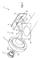
- reference numeral 1 indicates a device for focusing a laser light beam according to the present invention.
- the device 1 is an auto-focus device, that is, a device capable of controlling and automatically adjusting the wanted focusing distance of a laser light beam.
- the device 1 is intended for being used in a coded information reader and more preferably, in a barcode reader.
- the device 1 comprises a source 2 for emitting a laser light beam 10 along an optical emission path 10a and means 3 for focusing the laser light beam in a focusing point F located at a predetermined focusing distance D relative to the means 5 for detecting the focusing distance suitably provided in device 1 and described hereinafter.
- the source 2 for emitting the laser light beam is of the conventional type and therefore it is not described in detail herein.
- the focusing means 3 are of the conventional type and therefore they are not described in detail herein. In accordance with the present invention, however, such focusing means may be of a simpler and less expensive type than those typically used in conventional auto-focus devices: for example, the focusing means 3 may be composed of a single aspheric lens, optionally of a plastic material. The focusing means 3 may also be made using a variable focal lens, such as a liquid lens or a deformable surface mirror.
- the focusing means 3 or, in the case of focal variation optical devices, some of the components thereof, are operatively associated with moving means 4.
- Such moving means is adapted to control the movement of the focusing means 3 relative to the emission source 2 (or, in the case of focal variation optical devices, of some of the components thereof) for adjusting the focusing distance D of the focusing point F.
- the moving means 4 are of the conventional type and therefore they are not described in detail herein. In accordance with the present invention, however, the moving means 4 may be of a simpler and less expensive type than those typically used in conventional auto-focus devices, since in the device of the present invention, the accuracy of movements is not highly critical as in the devices of the prior art.
- the moving means 4 may consist of a simple voice-coil or of a piezoelectric actuator.
- the moving means 4 may be made with bimorph piezoelectric benders, with a lens arranged on the free end thereof.
- the focusing device 1 of the present invention further comprises means for the direct detection of the focusing distance D, indicated with reference numeral 5.
- Such means 5 detects the focusing distance generating a signal representative of the detected distance and, optionally, calculating a value of such distance.
- the detection means 5 acts in feedback on the moving means 4 for adjusting the position of the focusing means 3 relative to the light source 2 so as to change the focusing distance D of the focusing point F from an actual measured value to a different value.
- the detection of the actual focusing distance D and the following adjustment of the position of the focusing means 3, this adjustment being controlled by the moving means 4, is carried out iteratively until a wanted focusing distance is detected.
- the detection means 5 detects a parameter characteristic of the light beam leaving the focusing means 3 and representative of the focusing distance D at which the focusing means 3 focuses the light beam 10. Such detection is carried out using suitable detection means arranged in the optical emission path 10a and adapted to generate a signal representative of the detected parameter characteristic of the light beam leaving the focusing means 3 and means for processing said signal for generating a signal indicative of the actual focusing distance D and optionally, for calculating the numerical value thereof.
- the detection and processing means shall be described in detail in the continuation of the present description.
- the characteristic parameter detected by the detection means 5 is the wavefront radius of curvature of the light beam 10 leaving the focusing means 3.
- the wavefront of the focused light beam 10 consists of a spherical cap having a radius of curvature R equal to the focusing distance D.
- the detection of the wavefront radius of curvature R of the light beam 10 at the region immediately downstream of the focusing means provides a direct measurement of the actual focusing distance D.
- the detection means 5 comprises a sheet 20 with plane-parallel faces, respectively indicated with reference numerals 20a and 20b, having predetermined thickness and refractive index and located in the optical emission path 10a downstream of the focusing means 3.
- the sheet 20 is located at a distance from the focusing means 3 much smaller than the focusing distance D at which such means 3 focuses the light beam 10.
- the sheet 20 is inclined relative to the optical emission path 10a by a predetermined angle ⁇ , preferably equal to 45°.
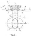
- Such sheet 20 acts as optical interferometer: it therefore generates a refracted light beam 11 that propagates along an optical path 11a substantially parallel to the optical emission path 10a and a pair of reflected light beams, indicated with reference numerals 12 and 13, which propagate along respective optical paths, indicated in figures 3 and 4 with reference numerals 12a and 13a, parallel to each other and inclined by angle 2 ⁇ relative to the optical emission path 10a (see, in particular, figure 3 ) .
- beams 12 and 13 have a light intensity comparable to one another and of a greater order of quantity than that of the secondary refracted beams that emerge from sheet 20 and that are generated by the chain of secondary refractions that begins in the sheet 20 starting from the light beam 13. The presence of the secondary refracted beams can therefore be disregarded.
- the sheet 20, the emission source 2 and the focusing means 3 are selected so that the thickness of the sheet 20 and the diameter of the light beam 10 emitted by the source 2 are very small as compared to the focusing distance D actuated by the focusing means 3. In these conditions, the light beams 12 and 13 are partly overlapped. A reflected beam 14 is thus generated which, at a central portion thereof corresponding to the overlapping zone of the light beams 12 and 13, exhibits an interference region 15 (see figures 3 and 4 ).
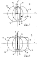
- the interference region 15 defines, on an observation plane P, a plurality of interference fringes that follow one another along a direction x.
- the wavefronts of the light beams 12 and 13 exhibit a radius of curvature R p ; such radius is smaller than the wavefront radius of curvature R of the focused light beam 10 by an amount equal to distance 1 of the observation plane P from the sheet 20 (see figure 3 ).
- Figure 4 clearly shows the interference region 15 defined by the partial overlapping of the light beams 12 and 13 and the projection of the light beams 12 and 13 on the observation plane P.
- the optical paths 12a and 13a are spaced by a distance s.
- a reference system of Cartesian axes x-y is defined on plane P with origin in the centre of the interference region 15, axis x parallel to the direction in which the interference fringes follow one another, axis y parallel to the fringes themselves and extending centrally in the interference region 15 and axis z parallel to the direction of propagation of the optical paths 12a and 13a but oriented in opposite direction relative to the direction of propagation.
- the phase difference between the light beams 12 and 13 is given, with good approximation, by the distance, measured along the axis z, between the wavefronts of such beams 12 and 13.
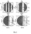
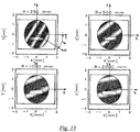
- Figure 5 shows, for example, the light distribution of the interference region 15 on the observation plane P as the focusing distance D varies.
- the interference fringes are clearly visible.
- Scales are expressed in mm and distance s between the two refracted light beams is equal to 0.604 mm.
- the profile therefore is sinusoidal, with a frequency depending on the wavefront radius of curvature R p of the beams 12 and 13.
- the measurement of the spatial frequency of the system of parallel fringes on the observation plane P and along the direction x provides a direct measurement of the wavefront radius of curvature of the focused light beam 10 and therefore, of the actual focusing distance D.
- the detection means 5 comprises, downstream of the sheet 20 in the optical reflection path, suitable photodetector means 30 adapted to generate a signal representative of the spatial frequency of the fringe system along the direction x of the observation plane P.
- suitable processing means (not shown, for example a microprocessor or microcontroller) adapted to process the above signal for generating a signal representative of the actual focusing distance D are provided.
- processing means may also provide a numerical value representative of the actual focusing distance D.
- the photodetector means 30 comprises, in particular, an array of photosensitive elements, globally indicated with reference numeral 31, aligned on the observation plane P along the direction x.
- photosensitive elements for example, are part of a CCD sensor.
- the determination of the spatial frequency of the fringe system along direction x is obtained in this case by measuring sequentially, along the direction x, the signal coming from each photosensitive element 31.
- the detection of the frequency of the temporal series of measurements in fact, is directly linked to the spatial frequency of the fringe system through the scanning speed of the array of photosensitive elements 31.
- the processing means generate an electrical signal, which may be of current or voltage based on the processing means used, proportional to the temporal frequency detected. Such signal is compared with a reference value corresponding to the required and/or wanted focusing distance.
- the function that links the reference value to the wavefront radius of curvature R of the focused beam, and therefore to the focusing distance, is predetermined in the calibration step of device 1. Such function depends on the type of adjustment means used, which may consist for example of a group with a mobile coil of the voice-coil type, of a piezoelectric actuator or else. Based on the comparison with the reference value, a signal is generated which is representative of the difference between the wanted focusing distance and the actual one; such signal is then used for the feedback, when needed, on the means for adjusting the focusing distance.
- the processing means may also provide a numerical value, readable by an operator, of the actual focusing distance D detected.
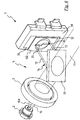
- FIG. 6 shows an embodiment of the device 1 of the present invention. Such embodiment differs from the one described above only in that in this embodiment, instead of an array of photosensitive elements 31, the photodetector means comprises a pair of photodiodes, indicated with reference numerals 32 and 33, arranged downstream of the observation plane P and adapted to detect different portions of the interference region 15.
- the photodetector means comprises a pair of photodiodes, indicated with reference numerals 32 and 33, arranged downstream of the observation plane P and adapted to detect different portions of the interference region 15.
- the observation plane P consists of a screen 100 having a pair of slits 34, 35 of rectangular shape.
- Photodiodes 32 and 33 are each arranged at a respective slit 34, 35.
- Slits 34, 35 allow the passage of two different portions of the interference region 15. Each of such portions is detected through a respective photodiode 32, 33.
- Figure 7 clearly shows the projection of beams 12 and 13 on the observation plane P. It is possible to see the slits 34 and 35 arranged in front of the respective photodiodes 32 and 33.
- the determination of the spatial frequency of the fringe system along the direction x is obtained, in this case, by calculating the difference ⁇ between the integral of the distribution of the light intensity at the two slits 34 and 35.
- the preferable arrangement for the two slits actually is that shown in figure 7 , wherein slits 34 and 35 extend from opposite sides relative to axis x and axis y.
- the longer sides of the slits coincide with axis y but face towards opposite sides relative to axis x and the shorter sides are parallel to axis x but face toward opposite sides relative to axis y.
- the slit 34 extends on the fourth quadrant and the slit 35 extends on the second quadrant of the reference system x-y defined on the observation plane P.
- the dimension L of slits 34 and 35 along the direction x is chosen so that the function of the difference of the integrals of the light intensity at the portion of the interference region 15 at the slits is monotonic for a predetermined range of the fringes frequency.
- variable x is considered, since the dependence on y is given by a multiplicative constant.
- the processing means generates a signal (in particular, a current or voltage depending on the processing means used) proportional to such difference.
- a signal in particular, a current or voltage depending on the processing means used
- Such signal is compared with a reference value corresponding to the required and/or wanted focusing distance.
- the function that links the reference value to the wavefront radius of curvature , and therefore to the focusing distance is predetermined in the calibration step of device 1 and depends on the type of moving means used.
- a signal is generated which is representative of the difference between the required focusing distance and the actual one; such signal is then used for the feedback, when needed, on the means for adjusting the focusing distance.
- the processing means may also provide a numerical value, readable by an operator, of the actual focusing distance D detected.
- the two slits 34, 35 extend symmetrically relative to axis y and are spaced relative to said axis by a predetermined distance d. Specifically, in such embodiment slit 34 is placed on the first and fourth quadrant of the reference system x-y whereas slit 35 is placed on the second and third quadrant. As for the rest, all the remarks made with reference to the embodiment of figure 6 apply. However, this alternative embodiment is less advantageous than the previous one since the integration area is smaller because the two slits 34 and 35 are not adjacent to axis y. In fact, the variation of the fringe frequency being equal, a greater variation of function ⁇ (L) and therefore a greater sensitivity and thus, higher accuracy in the adjustment of the moving, is associated with the configuration of figure 7 .
- the determination of the spatial frequency of the fringe system along the direction x is obtained, in this case, by calculating the integral of the distribution of the light intensity at the slit 37.
- the preferable arrangement for the slit 37 actually is that shown in figure 10 , wherein a longer side of the slit 37 is overlapped to axis y and the slit extends on opposite sides of the observation plane P relative to axis x.
- the slit 37 extends on the first and fourth quadrant of the reference system x-y defined on the observation plane P but it could also extend on the second and third quadrant.
- the dimension L of the slit 37 along the direction x is selected so that the integral function of the portion of the interference region 15 at the slit 37 is monotonic for a predetermined range of the fringe frequency.
- the processing means generates a signal proportional to such integral.
- such signal is compared with a reference value corresponding to the required and/or wanted focusing distance.
- the function that links the reference value to the wavefront radius of curvature , and therefore to the focusing distance, is predetermined in the calibration step of device 1 and depends on the type of moving means used.
- a signal is generated which is representative of the difference between the wanted focusing distance and the actual one; such signal is then used for the feedback, when needed, on the means for adjusting the focusing distance.
- the processing means may also provide a numerical value, readable by an operator, of the actual focusing distance D detected.
- Figure 11 shows a further optional embodiment of the device 1 of the present invention. Such embodiment differs from all the embodiments described above only in that in the optical reflection path, between the sheet 20 and the observation plane P, a conventional rotating polygonal mirror 40 is provided.
- Figure 11 shows a specific embodiment out of the invention wherein the photodetector means 30 comprises a photodiode 36 and the observation plane P comprises a screen 100 with a corresponding slit 37, as in the embodiment described above with reference to figure 9 .
- the interference region 15 is made to pass through the slit 37.
- Such passage determines a modulation of the light intensity of the interference region 15.
- v s the linear speed at which the light beams 12 and 13 are made to move on the slit 37
- f s is the spatial frequency of the fringe system along the direction x.
- the processing means calculates the spatial frequency and generates a signal proportional to such frequency. As for the embodiments described above, such signal is compared with a reference value corresponding to the required and/or wanted focusing distance.
- a signal is generated which is representative of the difference between the wanted focusing distance and the actual focusing distance; such signal is then used for the feedback, when needed, on the means for adjusting the focusing distance.
- the processing means may also provide a numerical value, readable by an operator, of the actual focusing distance D detected.
- All the above embodiments have the advantage of allowing a continuous detection of the focusing distance and thus, the possibility of adjusting such distance in real time. This is possible thanks to the fact that the means for detecting the focusing distance are located upstream of the means for scanning the laser light beam and thus, they are totally independent of one another.
- Figure 12 shows a further alternative embodiment of a device 1 out of the present invention.
- Such embodiment differs from that of figure 11 only in that the rotating polygonal mirror 40 is the same mirror that scans the refracted light beam 11 intended for sweeping the optical code to be read.
- a deflecting mirror 41 is provided in the optical reflection path, between the sheet 20 and the polygonal rotor 40.
- a light guide such as an optical fibre
- the positioning of the mirror 41 and of the slit 37 must be such that the detection of the intensity modulation coming from the light guide is temporally different from the detection of the light diffused by the optical code.
- This embodiment is particularly advantageous since it uses a same photodiode both for detecting the focusing distance and for detecting the information contents of the optical code.
- Figure 13 shows the light distribution of the interference region 15 on the observation plane P in the case of a further embodiment of the device 1 of the present invention.
- the sheet 20, instead of having plane-parallel faces, comprises plane faces forming such an angle ⁇ with each other as to allow overlapping of the light beams.
- the interference region 15 forms a system of parallel fringes on plane P that follow one another along a direction m inclined relative to axis x by a predetermined angle ⁇ .
- a sheet which consists of Schott BK7 glass, having thickness equal to 1 mm and angle ⁇ equal to 0.1° and several measurements were made as the focusing distance changed (and therefore, the wavefront radius of curvature R of the focused light beam). It is possible to see that as the radius of curvature varies, the inclination angle ⁇ of the fringes varies.
- the measurement of the angle ⁇ of rotation of the fringe system is therefore directly linked to the wavefront radius of curvature of the focused beam 10.
- a method for determining the angle ⁇ is described, for example, in US 4,604,739 and US 5,446,710 .
- the detection of the radius of curvature of the wavefront reflected by an optical support is carried out through a quadrant photodiode, that is, a photodiode consisting of four photosensitive elements placed side by side.
- the difference of the signal on the four photosensitive elements that occurs due to the fringe rotation is correlated to the angle of rotation of the fringes, and therefore to the wavefront radius of curvature of the focused light beam.
- the measurement of the angle ⁇ can be carried out through other types of sensors or with a suitable arrangement of a slit in front of a photodiode.
- the slit can be arranged parallel to axis x, as illustrated in figure 13 .
- the device 1 of the present invention allows carrying out a method for focusing a laser light beam, comprising the steps of:
- the step of detecting the focusing distance D and the step of adjusting the position of the focusing point F based on the detected focusing distance D are repeated iteratively until a wanted focusing distance is reached.
- the step of detecting the focusing distance D may comprise a step of calculating the actual value of such distance.
- the step of detecting the focusing distance D comprises, in particular, the steps of:
- the above processing step comprises, in particular, the step of determining the spatial frequency of a plurality of interference fringes defined by the interference region 15 on an observation plane P located in the optical reflection path, said interference fringes following one another along a direction of succession of the fringes.
- the step of determining the spatial frequency of said plurality of fringes comprises, in particular, the steps of:
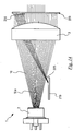
- the detection means 5 comprises a mirror-like surface 200 associated with an aperture diaphragm 220 arranged downstream of the focusing means 3 along the optical emission path 10a.
- a mirror-like surface 200 is inclined with respect to the optical emission path 10a such as to return backwards, through the same focusing means 3, a marginal portion 205 of the focused light beam 10 on a position different from that of the emission source 2. Said marginal portion 205 subtracted from the light beam 10 does not change the features thereof, since in any case it would be intercepted by the aperture diaphragm 220, which is needed to give to the beam the appropriate diameter for the expected use.
- the detection means 5 further comprises an optical sensor 210 integrally associated with the emission source 2 of the light beam 10 and sensitive to the incidence position of the marginal portion 205 returned backwards for generating a signal representative of the variation of such incidence position.
- the optical sensor 210 may be a conventional PSD.
- the sensor may consist of an array of photoelements, such as a CCD.
- the incidence position of the marginal portion 205 of the light beam returned backwards by the mirror-like surface 200 depends, the inclination of the mirror-like surface 200 relative to the optical emission path 10a being equal, on the radius of curvature of the focused laser light beam and thus, on the actual focusing distance D. If the mirror-like surface 200 were not inclined, the beam portion 205 returned backwards would go back to source 2, as this would be the point conjugate to the focus. The inclination of the mirror-like surface 200, instead, moves the beam portion 205 returned backwards to a decentralised position relative to source 2. Once a predetermined inclination has been established, the detection of the position wherein such beam portion 205 impinges the optical sensor 210 therefore provides a measurement of the actual focusing distance.
- Suitable processing means processes the signal generated by the optical sensor 210 for generating a signal proportional to the incidence position of the marginal portion 205 returned backwards. Such signal is compared with a reference value corresponding to the required and/or wanted focusing distance.
- the function that links the reference value to the wavefront radius of curvature (through the incidence position of the marginal portion 205 on the optical sensor 210), and therefore to the focusing distance is predetermined in the calibration step of device 1 and depends on the type of moving means used.
- a signal is generated which is representative of the difference between the wanted focusing distance and the actual focusing distance; such signal is then used for the feedback, when needed, on the means for adjusting the focusing distance.
- the processing means may also provide a numerical value, readable by an operator, of the actual focusing distance D detected.
- this embodiment has the advantage of allowing a continuous detection of the focusing distance and thus, the possibility of adjusting such distance in real time.
- the device 1 of the present invention in the embodiment of figure 14 , allows carrying out a method for focusing a laser light beam, comprising the steps of:
- the step of detecting the focusing distance D and the step of adjusting the position of the focusing point F based on the detected focusing distance D are repeated iteratively until a wanted focusing distance is reached.
- the step of detecting the actual focusing distance D may comprise a step of calculating the current value of such distance.
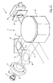
- Figure 15 shows a focusing device 1 comprising, besides the emission source 2 and the focusing means 3 discussed above, a sheet 50 having predetermined thickness and refractive index and provided with plane-parallel faces.
- One of such faces is treated so as to generate a single reflected beam 111 that propagates along a respective optical reflection path inclined relative to the optical emission path.
- face 20a can be treated with antireflective coating or face 20b can be treated with partially reflective coating, or both.
- means 60 for focusing the reflected beam 111 In the reflected optical path is provided means 60 for focusing the reflected beam 111, such means 60 being adapted to focus the reflected beam 111 at a predetermined distance.
- a diaphragm 70 In the reflected optical path, downstream of the focusing means 60, is provided a diaphragm 70 having an aperture 80 concentric to the reflected light beam 111, so as to let only a central portion of said light beam pass therethrough.
- the aperture 80 has a diameter equal to the diameter of the reflected light beam 111 at the diaphragm 70, measured in an operating condition wherein the focusing means 3 focuses the light beam 10 emitted by the emission source 2 at a maximum or minimum focusing distance D, that is, corresponding to one of the two required focusing ends Dmin and Dmax.
- a photodiode 90 is provided downstream of diaphragm 70.
- Such photodiode 90 is adapted to generate a signal bi-uniquely correlated to the focusing distance D, in particular such signal being representative of the variation of light intensity of the central portion of the reflected light beam 111 as the focusing distance D decreases or increases.
- means 60 focuses the reflected light beam 111 at a different distance than the previous operating condition, thus determining an increase of the diameter of the reflected light beam 111 at the diaphragm 70 and a corresponding decrease of the portion of such light beam that passes through the aperture 80.
- Suitable processing means processes the signal generated by the photodiode 90 for generating a signal proportional to the variation of light intensity of the central portion of the reflected light beam 111.
- Such signal is generated through a known relation between a plurality of values of such signal and a corresponding plurality of focusing distances. Such relation is predetermined during the calibration step.
- Such signal is then used for the feedback, when needed, on the means for adjusting the focusing distance.
- This embodiment has the advantage of allowing a continuous detection of the focusing distance and thus, the possibility of adjusting such distance in real time. This is possible thanks to the fact that the means for detecting the focusing distance are located upstream of the means for scanning the laser light beam and thus, they are totally independent of one another.
- the device 1 allows carrying out a method for focusing a laser light beam, comprising the following steps:
- the step of detecting the focusing distance D and the step of adjusting the position of the focusing point F based on the detected focusing distance D are repeated iteratively until a wanted focusing distance is reached.
- the step of detecting the actual focusing distance D may comprise a step of calculating the actual value of such distance.
- the device 1 of the present invention advantageously allows an accurate and reliable automatic (and, if needed, continuous and real time) adjustment of the wanted focusing distance irrespective of the occurrence of possible positioning errors and/or undesired movements of the mechanical and optical parts of the device itself and/or errors on the determination of the focal length of the optical focusing system.
Claims (12)
- Vorrichtung (1) zur Fokussierung eines Laserstrahls, umfassend:- eine Emissionsquelle (2) eines Laserstrahls (10) längs eines optischen Emissionspfades (10a);- erste Mittel zur Fokussierung (3) des Laserstrahls (10) auf eine Fokussierungsstelle (F), die in einer Fokussierungsentfernung (D) angeordnet ist;- Mittel zur Einstellung (4) der Position der Fokussierungsstelle (F) relativ zur Vorrichtung (1);- Mittel (5) zum Erfassen der Fokussierungsentfernung (D), die rückkoppelnd auf die Einstellmittel (4) wirken, wobei die Erfassungsmittel (5) einen Parameter erfassen, der charakteristisch für den Strahl (10) ist, der aus den ersten Fokussierungsmitteln (3) austritt und repräsentativ für die Fokussierungsentfernung (D) ist;wobei der charakteristische Parameter der Krümmungsradius der Wellenfront des Strahls (10) ist, der aus den ersten Fokussierungsmitteln (3) austritt, und wobei die Erfassungsmittel (5) Folgendes umfassen:- eine Glasplatte (20) mit vorgegebener Dicke und Brechungsindex, die auf dem optischen Emissionspfad (10a) stromabwärts der ersten Fokussierungsmittel (3) angeordnet und dazu geeignet ist, einen reflektierten Strahl (14) zu erzeugen, der sich längs eines reflektierten optischen Pfades fortpflanzt, der relativ zu dem optischen Emissionspfad (10a) geneigt ist, wobei der reflektierte Strahl (14) durch ein Paar von Strahlen (12, 13) definiert ist, die sich teilweise überlappen und einen Interferenzbereich (15) definieren, der eine Mehrzahl von Interferenzstreifen umfasst;- Fotodetektoren (30), die auf dem reflektierten optischen Pfad angeordnet und dazu geeignet sind, ein Signal zu erzeugen, das repräsentativ für die Ortsfrequenz der Interferenzstreifen ist, die durch wenigstens einen Abschnitt des Interferenzbereichs (15) auf einer auf dem reflektierten optischen Pfad angeordneten Beobachtungsebene (P) definiert sind, wobei der wenigstens eine Abschnitt des Interferenzbereichs (15) in einer Richtung (x) der Reihe von Streifen eine Abmessung aufweist, derart, dass für einen vorgegebenen Bereich der Ortsfrequenz der Interferenzstreifen die Integral-Funktion der Lichtintensität des reflektierten Strahls (14) in dem wenigstens einen Abschnitt des Interferenzbereichs (15) monoton ist, wobei die Fotodetektoren (30) zwei Fotodioden (32, 33) umfassen;- Mittel zum Verarbeiten des Signals, um ein Signal zu erzeugen, das auf den Krümmungsradius der Wellenfront des Strahls hinweist.
- Vorrichtung (1) nach Anspruch 1, wobei die Erfassungsmittel Mittel zum Verarbeiten umfassen, die einen Wert der Fokussierungsentfernung (D) berechnen.
- Vorrichtung (1) nach einem der vorstehenden Ansprüche, wobei der wenigstens eine Abschnitt des Interferenzbereichs (15) auf der Beobachtungsebene (P) durch zwei Schlitze (34, 35) definiert ist und die Fotodioden (32, 33) auf dem reflektierten optischen Pfad stromabwärts der beiden Schlitze (34, 35) angeordnet sind.
- Vorrichtung (1) nach Anspruch 3, wobei die beiden Schlitze (34, 35) rechteckig sind und eine kürzere Seite aufweisen, die längs der Richtung (x) der Reihe von Streifen gerichtet ist.
- Vorrichtung (1) nach Anspruch 3 oder 4, wobei jeweils eine Fotodiode (32, 33) für jeden der beiden Schlitze (34, 35) vorgesehen ist.
- Vorrichtung (1) nach Anspruch 5, sofern abhängig von Anspruch 4, wobei die beiden Schlitze (34, 35) auf gegenüberliegenden Seiten der Beobachtungsebene (P), relativ zu einer ersten Symmetrieachse (y) des Interferenzbereichs (15), senkrecht zur Richtung (x) der Reihe von Streifen gebildet sind.
- Vorrichtung (1) nach Anspruch 6, wobei die beiden Schlitze (34, 35) eine mit der ersten Symmetrieachse (y) zusammenfallende längere Seite aufweisen und auf gegenüberliegenden Seiten, relativ zu einer zweiten Symmetrieachse (x) des Interferenzbereichs (15), parallel zur Richtung (x) der Reihe von Streifen gebildet sind.
- Vorrichtung (1) nach Anspruch 6, wobei die beiden Schlitze (34, 35) sich symmetrisch relativ zu einer ersten Symmetrieachse (y) auf gegenüberliegenden Seiten der Beobachtungsebene (P), relativ zu einer zweiten Symmetrieachse (x) des Interferenzbereichs (15), parallel zur Richtung (x) der Reihe von Streifen erstrecken und relativ zu der ersten Symmetrieachse (y) in einer vorgegebenen Entfernung beabstandet sind.
- Vorrichtung (1) nach einem der vorstehenden Ansprüche, weiter umfassend einen rotierenden polygonalen Spiegel (40), der auf dem reflektierten optischen Pfad zwischen der Platte (20) und der Beobachtungsebene (P) angeordnet ist.
- Vorrichtung (1) nach Anspruch 9, weiter umfassend wenigstens einen Umlenkspiegel (41), der auf dem reflektierten optischen Pfad zwischen der Platte (20) und dem rotierenden polygonalen Spiegel (40) angeordnet ist, und wobei der rotierende polygonale Spiegel (40) auch auf einen von der Platte (20) erzeugten, gebrochenen Strahl wirkt.
- Vorrichtung (1) nach einem der vorstehenden Ansprüche, wobei die Platte (20) gegenüberliegende, planparallele Flächen (20a, 20b) aus reflektierendem Material umfasst.
- Vorrichtung (1) nach einem der vorstehenden Ansprüche, wobei die Platte (20) gegenüberliegende, plane Flächen (20a, 20b) aus reflektierendem Material umfasst, die einen Winkel θ miteinander einschließen.
Priority Applications (5)
| Application Number | Priority Date | Filing Date | Title |
|---|---|---|---|
| EP05425953.6A EP1804100B1 (de) | 2005-12-30 | 2005-12-30 | Verfahren und Vorrichtung zur Fokussierung eines Laserstrahls |
| US11/379,871 US7593114B2 (en) | 2005-12-30 | 2006-04-24 | Device and method for focusing a laser light beam |
| CN2006800498909A CN101351734B (zh) | 2005-12-30 | 2006-12-18 | 用于聚焦激光束的设备和方法 |
| PCT/EP2006/012169 WO2007076926A1 (en) | 2005-12-30 | 2006-12-18 | A device and a method for focusing a laser light beam |
| JP2008547874A JP5558720B2 (ja) | 2005-12-30 | 2006-12-18 | レーザ光ビームの焦点調節装置およびその方法 |
Applications Claiming Priority (1)
| Application Number | Priority Date | Filing Date | Title |
|---|---|---|---|
| EP05425953.6A EP1804100B1 (de) | 2005-12-30 | 2005-12-30 | Verfahren und Vorrichtung zur Fokussierung eines Laserstrahls |
Publications (2)
| Publication Number | Publication Date |
|---|---|
| EP1804100A1 EP1804100A1 (de) | 2007-07-04 |
| EP1804100B1 true EP1804100B1 (de) | 2018-02-21 |
Family
ID=36602699
Family Applications (1)
| Application Number | Title | Priority Date | Filing Date |
|---|---|---|---|
| EP05425953.6A Active EP1804100B1 (de) | 2005-12-30 | 2005-12-30 | Verfahren und Vorrichtung zur Fokussierung eines Laserstrahls |
Country Status (5)
| Country | Link |
|---|---|
| US (1) | US7593114B2 (de) |
| EP (1) | EP1804100B1 (de) |
| JP (1) | JP5558720B2 (de) |
| CN (1) | CN101351734B (de) |
| WO (1) | WO2007076926A1 (de) |
Families Citing this family (13)
| Publication number | Priority date | Publication date | Assignee | Title |
|---|---|---|---|---|
| WO2009061317A1 (en) * | 2007-11-08 | 2009-05-14 | Optoelectronics Co., Ltd. | Optical code scanner with automatic focusing |
| WO2009148456A1 (en) * | 2008-06-06 | 2009-12-10 | Optoelectronics Co., Ltd. | Autofocus control of an optical instrument |
| GB0816308D0 (en) | 2008-09-05 | 2008-10-15 | Mtt Technologies Ltd | Optical module |
| CN102231189B (zh) * | 2011-05-12 | 2016-04-13 | 天地融科技股份有限公司 | 一种图像采集装置 |
| CN102196181B (zh) * | 2011-05-13 | 2013-11-13 | 天地融科技股份有限公司 | 一种图像采集装置 |
| KR102038533B1 (ko) * | 2012-06-14 | 2019-10-31 | 한국전자통신연구원 | 레이저 레이더 시스템 및 목표물 영상 획득 방법 |
| DE102013215442A1 (de) * | 2013-08-06 | 2015-02-12 | Robert Bosch Gmbh | Vorrichtung zur Materialbearbeitung mit einem Laserstrahl |
| GB201316815D0 (en) * | 2013-09-23 | 2013-11-06 | Renishaw Plc | Additive manufacturing apparatus and method |
| DE102015215840B4 (de) | 2015-08-19 | 2017-03-23 | Fraunhofer-Gesellschaft zur Förderung der angewandten Forschung e.V. | Multiaperturabbildungsvorrichtung, Abbildungssystem und Verfahren zum Bereitstellen einer Multiaperturabbildungsvorrichtung |
| CN109874321B (zh) | 2015-10-30 | 2021-12-24 | 速尔特技术有限公司 | 增材制造系统和方法 |
| US10768404B2 (en) * | 2017-03-22 | 2020-09-08 | Mitutoyo Corporation | Modulation monitoring system for use with an imaging system that includes a high speed periodically modulated variable focal length lens |
| EP3824259A4 (de) | 2018-07-20 | 2022-03-30 | Ophir-Spiricon, LLC | Verfahren und vorrichtung zur fokuskorrektur von mehrbildlaserstrahlqualitätsmessungen |
| CN111722243A (zh) * | 2020-06-28 | 2020-09-29 | 上海兰宝传感科技股份有限公司 | 基于激光三角测量系统低温漂输出的温度补偿测距方法 |
Citations (1)
| Publication number | Priority date | Publication date | Assignee | Title |
|---|---|---|---|---|
| EP1710608A1 (de) * | 2005-04-07 | 2006-10-11 | Sick Ag | Vorrichtung und Verfahren zur Bestimmung der Fokuslage |
Family Cites Families (20)
| Publication number | Priority date | Publication date | Assignee | Title |
|---|---|---|---|---|
| JPS6017660A (ja) * | 1983-07-12 | 1985-01-29 | Matsushita Electric Ind Co Ltd | 給湯器 |
| JPS6026621U (ja) | 1983-07-28 | 1985-02-22 | アルプス電気株式会社 | 光学式ヘツド位置制御装置 |
| US4604739A (en) * | 1984-04-16 | 1986-08-05 | International Business Machines Corporation | Optical focus detection employing rotated interference patterns |
| JPH03168712A (ja) * | 1989-11-29 | 1991-07-22 | Victor Co Of Japan Ltd | オートフォーカス装置 |
| JPH05342608A (ja) * | 1992-06-05 | 1993-12-24 | Omron Corp | 焦点調整装置及び当該焦点調整装置を用いた発光装置、光ピックアップ装置、光学的コード読取装置ならびに光学検知装置。 |
| CN2127178Y (zh) * | 1992-06-18 | 1993-02-17 | 天津大学 | 激光干涉调焦装置 |
| US5338924A (en) * | 1992-08-11 | 1994-08-16 | Lasa Industries, Inc. | Apparatus and method for automatic focusing of light using a fringe plate |
| US5446710A (en) | 1992-11-06 | 1995-08-29 | International Business Machines Corporation | Focus error detection using an equal path length lateral shearing interferometer |
| US5689485A (en) | 1996-04-01 | 1997-11-18 | Discovision Associates | Tracking control apparatus and method |
| JPH09304016A (ja) * | 1996-05-15 | 1997-11-28 | Nikon Corp | 面位置検出装置及び該装置を備えた露光装置 |
| JP3693767B2 (ja) * | 1996-09-13 | 2005-09-07 | オリンパス株式会社 | 形状測定器 |
| DE19726581C5 (de) | 1997-06-23 | 2010-02-04 | Sick Ag | Verfahren zur Bestimmung der Fokuslage einer optoelektronischen Vorrichtung |
| JPH11194018A (ja) * | 1998-01-06 | 1999-07-21 | Nikon Corp | 被写体情報測定装置 |
| JPH11214299A (ja) * | 1998-01-27 | 1999-08-06 | Komatsu Ltd | ドットマークの読み取り装置と読み取り方法 |
| US6288986B1 (en) * | 1999-01-12 | 2001-09-11 | Siros Technologies, Inc. | Focus error signal generation using a birefringent plate with confocal detection |
| JP4027605B2 (ja) * | 2001-01-26 | 2007-12-26 | 株式会社リコー | 光学面の形状測定方法および装置および記録媒体 |
| US6794625B2 (en) * | 2001-05-15 | 2004-09-21 | Applied Materials | Dynamic automatic focusing method and apparatus using interference patterns |
| JP2003030867A (ja) | 2001-07-13 | 2003-01-31 | Hitachi Ltd | フォーカス制御方法及び装置とそれを用いた原盤露光装置 |
| US6621060B1 (en) | 2002-03-29 | 2003-09-16 | Photonics Research Ontario | Autofocus feedback positioning system for laser processing |
| JP2005221702A (ja) * | 2004-02-05 | 2005-08-18 | Noritsu Koki Co Ltd | 投影装置 |
-
2005
- 2005-12-30 EP EP05425953.6A patent/EP1804100B1/de active Active
-
2006
- 2006-04-24 US US11/379,871 patent/US7593114B2/en active Active
- 2006-12-18 CN CN2006800498909A patent/CN101351734B/zh active Active
- 2006-12-18 WO PCT/EP2006/012169 patent/WO2007076926A1/en active Application Filing
- 2006-12-18 JP JP2008547874A patent/JP5558720B2/ja active Active
Patent Citations (1)
| Publication number | Priority date | Publication date | Assignee | Title |
|---|---|---|---|---|
| EP1710608A1 (de) * | 2005-04-07 | 2006-10-11 | Sick Ag | Vorrichtung und Verfahren zur Bestimmung der Fokuslage |
Also Published As
| Publication number | Publication date |
|---|---|
| CN101351734B (zh) | 2011-12-14 |
| JP2009525493A (ja) | 2009-07-09 |
| CN101351734A (zh) | 2009-01-21 |
| JP5558720B2 (ja) | 2014-07-23 |
| US20070153644A1 (en) | 2007-07-05 |
| EP1804100A1 (de) | 2007-07-04 |
| US7593114B2 (en) | 2009-09-22 |
| WO2007076926A1 (en) | 2007-07-12 |
Similar Documents
| Publication | Publication Date | Title |
|---|---|---|
| EP1804100B1 (de) | Verfahren und Vorrichtung zur Fokussierung eines Laserstrahls | |
| JP5795532B2 (ja) | レーザ自己混合測定装置 | |
| JP6044315B2 (ja) | 変位計測方法および変位計測装置 | |
| KR101511344B1 (ko) | 위치 탐지기 및 광 편향 장치 | |
| CN103673887A (zh) | 共聚焦计测装置 | |
| US20040155178A1 (en) | Optical encoder and output adjustment for the same | |
| US6472658B2 (en) | Photoelectric position measuring system that optimizes modulation of a scanning device and the intensity of a reference mark signal | |
| JP2009525493A5 (de) | ||
| US4985624A (en) | Optical grating sensor and method of monitoring with a multi-period grating | |
| EP0985133B1 (de) | Vorrichtung zur positionsbestmmung | |
| US5410397A (en) | Method and apparatus for holographic wavefront diagnostics | |
| US6490028B1 (en) | Variable pitch grating for diffraction range finding system | |
| JP2009543087A (ja) | スケールおよび読み取りヘッド | |
| US5012090A (en) | Optical grating sensor and method of monitoring having a multi-period grating | |
| EP0247067B1 (de) | Bestimmung des halbleiter-wellenfrontgefälles | |
| EP0489399B1 (de) | Verschiebungsdetektor | |
| JP7248504B2 (ja) | 光学式エンコーダ | |
| US20010028036A1 (en) | Wavelength dispersive infrared detector and microspectrometer using microcantilevers | |
| US20060226335A1 (en) | Apparatus and a method for the determination of the focal distance | |
| US5815272A (en) | Filter for laser gaging system | |
| JP3560692B2 (ja) | 光学式エンコーダ | |
| CN112789479A (zh) | 激光三角测量设备和校准方法 | |
| JP3639377B2 (ja) | 光学式変位センサ | |
| US20220163319A1 (en) | Displacement sensor and profile measurement apparatus | |
| JPH07270121A (ja) | 位置センサ |
Legal Events
| Date | Code | Title | Description |
|---|---|---|---|
| PUAI | Public reference made under article 153(3) epc to a published international application that has entered the european phase |
Free format text: ORIGINAL CODE: 0009012 |
|
| AK | Designated contracting states |
Kind code of ref document: A1 Designated state(s): AT BE BG CH CY CZ DE DK EE ES FI FR GB GR HU IE IS IT LI LT LU LV MC NL PL PT RO SE SI SK TR |
|
| AX | Request for extension of the european patent |
Extension state: AL BA HR MK YU |
|
| 17P | Request for examination filed |
Effective date: 20080103 |
|
| 17Q | First examination report despatched |
Effective date: 20080208 |
|
| AKX | Designation fees paid |
Designated state(s): AT BE BG CH CY CZ DE DK EE ES FI FR GB GR HU IE IS IT LI LT LU LV MC NL PL PT RO SE SI SK TR |
|
| RAP1 | Party data changed (applicant data changed or rights of an application transferred) |
Owner name: DATALOGIC IP TECH S.R.L. |
|
| GRAP | Despatch of communication of intention to grant a patent |
Free format text: ORIGINAL CODE: EPIDOSNIGR1 |
|
| INTG | Intention to grant announced |
Effective date: 20170725 |
|
| GRAS | Grant fee paid |
Free format text: ORIGINAL CODE: EPIDOSNIGR3 |
|
| GRAA | (expected) grant |
Free format text: ORIGINAL CODE: 0009210 |
|
| AK | Designated contracting states |
Kind code of ref document: B1 Designated state(s): AT BE BG CH CY CZ DE DK EE ES FI FR GB GR HU IE IS IT LI LT LU LV MC NL PL PT RO SE SI SK TR |
|
| REG | Reference to a national code |
Ref country code: GB Ref legal event code: FG4D |
|
| REG | Reference to a national code |
Ref country code: CH Ref legal event code: EP |
|
| REG | Reference to a national code |
Ref country code: AT Ref legal event code: REF Ref document number: 972358 Country of ref document: AT Kind code of ref document: T Effective date: 20180315 |
|
| REG | Reference to a national code |
Ref country code: IE Ref legal event code: FG4D |
|
| REG | Reference to a national code |
Ref country code: DE Ref legal event code: R096 Ref document number: 602005053516 Country of ref document: DE |
|
| REG | Reference to a national code |
Ref country code: NL Ref legal event code: MP Effective date: 20180221 |
|
| REG | Reference to a national code |
Ref country code: LT Ref legal event code: MG4D |
|
| REG | Reference to a national code |
Ref country code: AT Ref legal event code: MK05 Ref document number: 972358 Country of ref document: AT Kind code of ref document: T Effective date: 20180221 |
|
| PG25 | Lapsed in a contracting state [announced via postgrant information from national office to epo] |
Ref country code: FI Free format text: LAPSE BECAUSE OF FAILURE TO SUBMIT A TRANSLATION OF THE DESCRIPTION OR TO PAY THE FEE WITHIN THE PRESCRIBED TIME-LIMIT Effective date: 20180221 Ref country code: CY Free format text: LAPSE BECAUSE OF FAILURE TO SUBMIT A TRANSLATION OF THE DESCRIPTION OR TO PAY THE FEE WITHIN THE PRESCRIBED TIME-LIMIT Effective date: 20180221 Ref country code: ES Free format text: LAPSE BECAUSE OF FAILURE TO SUBMIT A TRANSLATION OF THE DESCRIPTION OR TO PAY THE FEE WITHIN THE PRESCRIBED TIME-LIMIT Effective date: 20180221 Ref country code: NL Free format text: LAPSE BECAUSE OF FAILURE TO SUBMIT A TRANSLATION OF THE DESCRIPTION OR TO PAY THE FEE WITHIN THE PRESCRIBED TIME-LIMIT Effective date: 20180221 Ref country code: LT Free format text: LAPSE BECAUSE OF FAILURE TO SUBMIT A TRANSLATION OF THE DESCRIPTION OR TO PAY THE FEE WITHIN THE PRESCRIBED TIME-LIMIT Effective date: 20180221 |
|
| PG25 | Lapsed in a contracting state [announced via postgrant information from national office to epo] |
Ref country code: GR Free format text: LAPSE BECAUSE OF FAILURE TO SUBMIT A TRANSLATION OF THE DESCRIPTION OR TO PAY THE FEE WITHIN THE PRESCRIBED TIME-LIMIT Effective date: 20180522 Ref country code: SE Free format text: LAPSE BECAUSE OF FAILURE TO SUBMIT A TRANSLATION OF THE DESCRIPTION OR TO PAY THE FEE WITHIN THE PRESCRIBED TIME-LIMIT Effective date: 20180221 Ref country code: LV Free format text: LAPSE BECAUSE OF FAILURE TO SUBMIT A TRANSLATION OF THE DESCRIPTION OR TO PAY THE FEE WITHIN THE PRESCRIBED TIME-LIMIT Effective date: 20180221 Ref country code: AT Free format text: LAPSE BECAUSE OF FAILURE TO SUBMIT A TRANSLATION OF THE DESCRIPTION OR TO PAY THE FEE WITHIN THE PRESCRIBED TIME-LIMIT Effective date: 20180221 Ref country code: BG Free format text: LAPSE BECAUSE OF FAILURE TO SUBMIT A TRANSLATION OF THE DESCRIPTION OR TO PAY THE FEE WITHIN THE PRESCRIBED TIME-LIMIT Effective date: 20180521 |
|
| PG25 | Lapsed in a contracting state [announced via postgrant information from national office to epo] |
Ref country code: PL Free format text: LAPSE BECAUSE OF FAILURE TO SUBMIT A TRANSLATION OF THE DESCRIPTION OR TO PAY THE FEE WITHIN THE PRESCRIBED TIME-LIMIT Effective date: 20180221 Ref country code: EE Free format text: LAPSE BECAUSE OF FAILURE TO SUBMIT A TRANSLATION OF THE DESCRIPTION OR TO PAY THE FEE WITHIN THE PRESCRIBED TIME-LIMIT Effective date: 20180221 Ref country code: IT Free format text: LAPSE BECAUSE OF FAILURE TO SUBMIT A TRANSLATION OF THE DESCRIPTION OR TO PAY THE FEE WITHIN THE PRESCRIBED TIME-LIMIT Effective date: 20180221 Ref country code: RO Free format text: LAPSE BECAUSE OF FAILURE TO SUBMIT A TRANSLATION OF THE DESCRIPTION OR TO PAY THE FEE WITHIN THE PRESCRIBED TIME-LIMIT Effective date: 20180221 |
|
| REG | Reference to a national code |
Ref country code: DE Ref legal event code: R097 Ref document number: 602005053516 Country of ref document: DE |
|
| PG25 | Lapsed in a contracting state [announced via postgrant information from national office to epo] |
Ref country code: CZ Free format text: LAPSE BECAUSE OF FAILURE TO SUBMIT A TRANSLATION OF THE DESCRIPTION OR TO PAY THE FEE WITHIN THE PRESCRIBED TIME-LIMIT Effective date: 20180221 Ref country code: SK Free format text: LAPSE BECAUSE OF FAILURE TO SUBMIT A TRANSLATION OF THE DESCRIPTION OR TO PAY THE FEE WITHIN THE PRESCRIBED TIME-LIMIT Effective date: 20180221 Ref country code: DK Free format text: LAPSE BECAUSE OF FAILURE TO SUBMIT A TRANSLATION OF THE DESCRIPTION OR TO PAY THE FEE WITHIN THE PRESCRIBED TIME-LIMIT Effective date: 20180221 |
|
| PLBE | No opposition filed within time limit |
Free format text: ORIGINAL CODE: 0009261 |
|
| STAA | Information on the status of an ep patent application or granted ep patent |
Free format text: STATUS: NO OPPOSITION FILED WITHIN TIME LIMIT |
|
| 26N | No opposition filed |
Effective date: 20181122 |
|
| PG25 | Lapsed in a contracting state [announced via postgrant information from national office to epo] |
Ref country code: SI Free format text: LAPSE BECAUSE OF FAILURE TO SUBMIT A TRANSLATION OF THE DESCRIPTION OR TO PAY THE FEE WITHIN THE PRESCRIBED TIME-LIMIT Effective date: 20180221 |
|
| REG | Reference to a national code |
Ref country code: CH Ref legal event code: PL |
|
| PG25 | Lapsed in a contracting state [announced via postgrant information from national office to epo] |
Ref country code: MC Free format text: LAPSE BECAUSE OF FAILURE TO SUBMIT A TRANSLATION OF THE DESCRIPTION OR TO PAY THE FEE WITHIN THE PRESCRIBED TIME-LIMIT Effective date: 20180221 Ref country code: LU Free format text: LAPSE BECAUSE OF NON-PAYMENT OF DUE FEES Effective date: 20181230 |
|
| REG | Reference to a national code |
Ref country code: BE Ref legal event code: MM Effective date: 20181231 Ref country code: IE Ref legal event code: MM4A |
|
| PG25 | Lapsed in a contracting state [announced via postgrant information from national office to epo] |
Ref country code: IE Free format text: LAPSE BECAUSE OF NON-PAYMENT OF DUE FEES Effective date: 20181230 |
|
| PG25 | Lapsed in a contracting state [announced via postgrant information from national office to epo] |
Ref country code: BE Free format text: LAPSE BECAUSE OF NON-PAYMENT OF DUE FEES Effective date: 20181231 |
|
| PG25 | Lapsed in a contracting state [announced via postgrant information from national office to epo] |
Ref country code: CH Free format text: LAPSE BECAUSE OF NON-PAYMENT OF DUE FEES Effective date: 20181231 Ref country code: LI Free format text: LAPSE BECAUSE OF NON-PAYMENT OF DUE FEES Effective date: 20181231 |
|
| PG25 | Lapsed in a contracting state [announced via postgrant information from national office to epo] |
Ref country code: TR Free format text: LAPSE BECAUSE OF FAILURE TO SUBMIT A TRANSLATION OF THE DESCRIPTION OR TO PAY THE FEE WITHIN THE PRESCRIBED TIME-LIMIT Effective date: 20180221 |
|
| PG25 | Lapsed in a contracting state [announced via postgrant information from national office to epo] |
Ref country code: PT Free format text: LAPSE BECAUSE OF FAILURE TO SUBMIT A TRANSLATION OF THE DESCRIPTION OR TO PAY THE FEE WITHIN THE PRESCRIBED TIME-LIMIT Effective date: 20180221 |
|
| PG25 | Lapsed in a contracting state [announced via postgrant information from national office to epo] |
Ref country code: HU Free format text: LAPSE BECAUSE OF FAILURE TO SUBMIT A TRANSLATION OF THE DESCRIPTION OR TO PAY THE FEE WITHIN THE PRESCRIBED TIME-LIMIT; INVALID AB INITIO Effective date: 20051230 |
|
| PG25 | Lapsed in a contracting state [announced via postgrant information from national office to epo] |
Ref country code: IS Free format text: LAPSE BECAUSE OF FAILURE TO SUBMIT A TRANSLATION OF THE DESCRIPTION OR TO PAY THE FEE WITHIN THE PRESCRIBED TIME-LIMIT Effective date: 20180621 |
|
| P01 | Opt-out of the competence of the unified patent court (upc) registered |
Effective date: 20230525 |
|
| PGFP | Annual fee paid to national office [announced via postgrant information from national office to epo] |
Ref country code: GB Payment date: 20231220 Year of fee payment: 19 |
|
| PGFP | Annual fee paid to national office [announced via postgrant information from national office to epo] |
Ref country code: FR Payment date: 20231221 Year of fee payment: 19 Ref country code: DE Payment date: 20231214 Year of fee payment: 19 |