EP1801384B1 - Procédés et systèmes de contrôle du turbocompresseur à géométrie variable - Google Patents
Procédés et systèmes de contrôle du turbocompresseur à géométrie variable Download PDFInfo
- Publication number
- EP1801384B1 EP1801384B1 EP07101997A EP07101997A EP1801384B1 EP 1801384 B1 EP1801384 B1 EP 1801384B1 EP 07101997 A EP07101997 A EP 07101997A EP 07101997 A EP07101997 A EP 07101997A EP 1801384 B1 EP1801384 B1 EP 1801384B1
- Authority
- EP
- European Patent Office
- Prior art keywords
- speed
- target
- err
- boost
- turbo
- Prior art date
- Legal status (The legal status is an assumption and is not a legal conclusion. Google has not performed a legal analysis and makes no representation as to the accuracy of the status listed.)
- Expired - Fee Related
Links
- 238000000034 method Methods 0.000 title claims description 40
- 230000008859 change Effects 0.000 claims description 25
- 238000002485 combustion reaction Methods 0.000 claims description 10
- 239000000446 fuel Substances 0.000 description 35
- 230000006870 function Effects 0.000 description 9
- 230000007246 mechanism Effects 0.000 description 8
- 230000001276 controlling effect Effects 0.000 description 5
- 238000013461 design Methods 0.000 description 5
- 238000001514 detection method Methods 0.000 description 5
- 238000010586 diagram Methods 0.000 description 4
- 238000013507 mapping Methods 0.000 description 3
- 230000001105 regulatory effect Effects 0.000 description 3
- 230000004044 response Effects 0.000 description 3
- 238000013459 approach Methods 0.000 description 2
- 238000004891 communication Methods 0.000 description 2
- 230000000295 complement effect Effects 0.000 description 2
- 230000006378 damage Effects 0.000 description 2
- 238000001914 filtration Methods 0.000 description 2
- 238000005259 measurement Methods 0.000 description 2
- 239000000203 mixture Substances 0.000 description 2
- 230000009467 reduction Effects 0.000 description 2
- 230000001419 dependent effect Effects 0.000 description 1
- 230000000694 effects Effects 0.000 description 1
- 230000009528 severe injury Effects 0.000 description 1
- 230000011664 signaling Effects 0.000 description 1
- 238000009987 spinning Methods 0.000 description 1
- 230000001960 triggered effect Effects 0.000 description 1
- 238000011144 upstream manufacturing Methods 0.000 description 1
Images


Classifications
-
- F—MECHANICAL ENGINEERING; LIGHTING; HEATING; WEAPONS; BLASTING
- F02—COMBUSTION ENGINES; HOT-GAS OR COMBUSTION-PRODUCT ENGINE PLANTS
- F02B—INTERNAL-COMBUSTION PISTON ENGINES; COMBUSTION ENGINES IN GENERAL
- F02B37/00—Engines characterised by provision of pumps driven at least for part of the time by exhaust
- F02B37/12—Control of the pumps
- F02B37/24—Control of the pumps by using pumps or turbines with adjustable guide vanes
-
- F—MECHANICAL ENGINEERING; LIGHTING; HEATING; WEAPONS; BLASTING
- F01—MACHINES OR ENGINES IN GENERAL; ENGINE PLANTS IN GENERAL; STEAM ENGINES
- F01D—NON-POSITIVE DISPLACEMENT MACHINES OR ENGINES, e.g. STEAM TURBINES
- F01D17/00—Regulating or controlling by varying flow
- F01D17/10—Final actuators
- F01D17/12—Final actuators arranged in stator parts
- F01D17/14—Final actuators arranged in stator parts varying effective cross-sectional area of nozzles or guide conduits
-
- F—MECHANICAL ENGINEERING; LIGHTING; HEATING; WEAPONS; BLASTING
- F02—COMBUSTION ENGINES; HOT-GAS OR COMBUSTION-PRODUCT ENGINE PLANTS
- F02D—CONTROLLING COMBUSTION ENGINES
- F02D23/00—Controlling engines characterised by their being supercharged
-
- F—MECHANICAL ENGINEERING; LIGHTING; HEATING; WEAPONS; BLASTING
- F02—COMBUSTION ENGINES; HOT-GAS OR COMBUSTION-PRODUCT ENGINE PLANTS
- F02D—CONTROLLING COMBUSTION ENGINES
- F02D41/00—Electrical control of supply of combustible mixture or its constituents
- F02D41/0002—Controlling intake air
- F02D41/0007—Controlling intake air for control of turbo-charged or super-charged engines
-
- F—MECHANICAL ENGINEERING; LIGHTING; HEATING; WEAPONS; BLASTING
- F02—COMBUSTION ENGINES; HOT-GAS OR COMBUSTION-PRODUCT ENGINE PLANTS
- F02D—CONTROLLING COMBUSTION ENGINES
- F02D41/00—Electrical control of supply of combustible mixture or its constituents
- F02D41/02—Circuit arrangements for generating control signals
- F02D41/14—Introducing closed-loop corrections
- F02D41/1401—Introducing closed-loop corrections characterised by the control or regulation method
- F02D2041/1409—Introducing closed-loop corrections characterised by the control or regulation method using at least a proportional, integral or derivative controller
-
- F—MECHANICAL ENGINEERING; LIGHTING; HEATING; WEAPONS; BLASTING
- F02—COMBUSTION ENGINES; HOT-GAS OR COMBUSTION-PRODUCT ENGINE PLANTS
- F02D—CONTROLLING COMBUSTION ENGINES
- F02D41/00—Electrical control of supply of combustible mixture or its constituents
- F02D41/02—Circuit arrangements for generating control signals
- F02D41/14—Introducing closed-loop corrections
- F02D41/1401—Introducing closed-loop corrections characterised by the control or regulation method
- F02D2041/141—Introducing closed-loop corrections characterised by the control or regulation method using a feed-forward control element
-
- Y—GENERAL TAGGING OF NEW TECHNOLOGICAL DEVELOPMENTS; GENERAL TAGGING OF CROSS-SECTIONAL TECHNOLOGIES SPANNING OVER SEVERAL SECTIONS OF THE IPC; TECHNICAL SUBJECTS COVERED BY FORMER USPC CROSS-REFERENCE ART COLLECTIONS [XRACs] AND DIGESTS
- Y02—TECHNOLOGIES OR APPLICATIONS FOR MITIGATION OR ADAPTATION AGAINST CLIMATE CHANGE
- Y02T—CLIMATE CHANGE MITIGATION TECHNOLOGIES RELATED TO TRANSPORTATION
- Y02T10/00—Road transport of goods or passengers
- Y02T10/10—Internal combustion engine [ICE] based vehicles
- Y02T10/12—Improving ICE efficiencies
Definitions
- the present invention relates generally to the field of variable geometry turbocharger design and, more particularly, to method and system for controlling the position of a variable geometry member disposed within a variable geometry turbocharger.
- Turbochargers are devices that are frequently used to increase the output of an internal combustion engine.
- a typical turbocharger comprises a turbine wheel coupled to a compressor impeller by a common shaft.
- Exhaust gas from the engine is diverted into a turbine housing of the turbocharger and through an inlet nozzle.
- the exhaust gas is directed onto the turbine wheel, causing it to spin, which in turn spins the common shaft and the compressor impeller.
- the compressor impeller is disposed within a compressor housing having an air inlet and a pressurized or boosted air outlet.
- the spinning compressor impeller operates to pressurize air entering the compressor housing and generate a pressurized or boosted air stream that is directed into an inlet system of the internal combustion engine.
- This boosted air is mixed with fuel to provide a combustible mixture within the combustion chambers of an engine.
- the turbocharger operates to provide a larger air mass and fuel mixture, than otherwise provided via an ambient pressure air intake stream, that results in a greater engine output during combustion.
- the gain in engine output that can be achieved is directly proportional to the increase in intake air flow pressure generated by the turbocharger.
- allowing the boost pressure to reach too high a level can result in severe damage to both the turbocharger and the engine, particularly when the engine has to operate beyond its intended performance range.
- an objective of turbocharger design is to regulate or control the boost pressure provided by the turbocharger in a manner that optimizes engine power output at different engine operating conditions without causing engine damage.
- a known technique for regulating boost pressure is by using a turbocharger having a variable geometry member that functions to control the amount of exhaust gas directed to the turbine wheel. Turbochargers comprising such variable geometry members are referred to as variable geometry turbochargers (VGTs).
- VGT includes a variable geometry member in the form of multiple adjustable-position vanes that are positioned within the turbine housing, and that are movable within in inlet nozzle of the turbine housing to regulate the amount of exhaust gas that is passed to the turbine wheel.
- the vanes in this type of VGT can be opened to permit greater gas flow across the turbine wheel, causing the turbine wheel to spin at a higher speed and raise the boost pressure, or closed to restrict exhaust gas flow to the turbine, thereby reducing the boost pressure.
- the amount of boost pressure generated by this type of VGT can be regulated by varying the vane position so as to optimize engine output while avoiding engine damage.
- variable geometry member in this or any type of VGT, be operated in a manner that will produce the desired change. Since this operation is taking place in a dynamic system of changing VGT and engine operating parameters, it is desired that a control system be used to for the purpose of taking these dynamic operating conditions into account for the purpose of provide the desired result.
- WO0155575A and W00159275A Other examples of prior art devices can be found in WO0155575A and W00159275A .
- a control system be devised that is capable of being used with a VGT to effect a desired change in the variable geometry member disposed therein for the purpose of achieving a desired VGT and engine output.
- the present invention discloses a method for positioning a variable geometry member disposed within a turbocharger that is coupled to an internal combustion engine, said method comprising the steps of:
- the step of determining said first new variable geometry member position may comprise the steps of:
- the present invention provides a system for positioning a variable geometry member disposed within a turbocharger that is coupled to an internal combustion engine, said system comprising:
- the first and second turbo speed target and the new variable geometry member position can be generated using a modified PID technique.
- the change in turbo speed needed to achieve the first turbo speed target may first be determined and then summed with the actual turbo speed to generate the first turbo speed target, wherein the change in turbo speed, ⁇ speed , is substantially equal to kp(err boost ) + k d (err boost )/dt.
- the second turbo speed target can be generated by adding the change in turbo speed, ⁇ speed , to the actual turbo speed, where ⁇ speed is substantially equal to k p (err turbine ) + k d (err turbine )/dt.
- the new variable geometry member position may be generated by first calculating the change in variable geometry member position, ⁇ ⁇ , and then summing ⁇ ⁇ with the variable geometry member position of the preceding iteration, where ⁇ ⁇ is substantially equal to k p (err speed ) + k d (err speed )/dt.
- Control systems constructed according to principles of this invention, for variable geometry turbochargers (VGTs) are specifically designed to govern the flow of exhaust gas to a turbine wheel in the turbocharger, thereby controlling pressurized air output by the turbocharger.
- VVTs variable geometry turbochargers
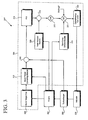
- FIG. 1 illustrates a turbocharged internal combustion engine system 100 comprising a control system according to one embodiment of this invention
- the engine system comprises an internal combustion engine 102, and engine control unit (ECU) 104, and actuator 106, and a VGT 108 in air and exhaust flow communication with the engine.
- the VGT includes one or more variable geometry members that are movably disposed therein, and that are coupled to the actuator for movement/position control.
- the ECU 104 can include a boost target map 110, a boost target correcting module 112, a proportional/integral/differential (PID) module 114, an open loop map 116, a fault detection module 118, a feed forward module 120, and a digital/analog (D/A) converter 122.
- the VGT 108 can include a variable geometry member in the form of a number of aerodynamic vanes that are movably attached to an inlet nozzle of the VGT turbine, and that are positioned upstream from a turbine wheel disposed within the housing.
- An example VGT of this type is disclosed in U.S. Patent No. 6,269, 642 .
- the position of the vanes in the VGT 108 is controlled by the actuator 106, which can be configured to pivot the vanes in unison incrementally to control the throat area of the inlet nozzle, and thereby, control the amount of exhaust gas that flows into the VGT 108.
- the actuator 106 can be one of suitable design known in the art, for example, a position-dependent actuator design.
- a suitable actuator design is disclosed in U.S. Patent Number No. 6,269,642 .
- the actuator 106 can be an electrical actuator with position feedback configured to communicate with the ECU 104 as part of a controller area network (CAN), which is a communication standard frequently used for in-vehicle control.
- CAN controller area network
- sensors can be used to measure the quantity of fuel flow to engine 102, as well as the engine speed of engine 102, in a manner known in the art. It is noted that fuel quantity and engine speed are also referred to as "engine parameters" in the present application.
- the fuel quantity and engine speed measured by the sensors are fed into the boost target map 110.
- the boost target map 110 can be a map stored in a memory component of the ECU 104, for example, containing desired boost pressure data for a given fuel quantity or engine speed. Based on the fuel quantity or engine speed, a boost target is determined from boost target map 110. In one embodiment, braking status of the vehicle can also be factored into the determination of the boost target.
- the boost target is input into the boost target correcting module 112, which also receives input from sensors that measure the ambient pressure, P o .
- One function of the boost target correcting module 112 is to prevent the VGT 108 from overspeeding in instances where the ambient pressure is relatively low, such that meeting the boost target would overspeed the turbocharger.
- the boost target correcting module 112 can determine a maximum permissible boost as a function of the ambient pressure, the engine speed, and the turbocharger speed limit. If the boost target that is determined from the boost target map 110 exceeds the maximum permissible boost, then the boost target correcting module 112 can reduce the boost target to a permissible level. In this manner, the boost target correcting module 112 can be configured to adjust the boost target in instances where the boost target could result in overspeeding the turbocharger.
- the corrected boost target generated by the boost target correcting module 112 is then compared to the actual boost at summing node 113 to determine the error between the boost target and the actual boost.
- the error value which is also referred to as "err" in the present application, is fed into the PID module 114.
- the PID module 114 can be configured to determine a new variable geometry member, e.g., vane position, ⁇ new , to achieve the boost target utilizing a suitable PID filtering method known in the art.
- the PID module 114 can be configured to calculate the change in vane position, i.e., ⁇ ⁇ , needed in order to meet the boost target.
- a new vane position i.e.
- ⁇ new is then determined by summing ⁇ ⁇ and ⁇ old at the summing node 115. Once ⁇ new has been determined, other corrective/diagnostic mechanisms can be utilized to enhance the level of control.
- an open loop diagnostic mechanism can be implemented wherein a target vane position, ⁇ target, is determined from open an loop map 116.
- the open loop map 116 can be, for example, a map stored in a memory component in the ECU 104 that, based only on fuel quantity and engine speed, plots a desired vane position for different fuel quantities and engine speeds.
- ⁇ new and ⁇ target can then be inputted into a fault detection module 118, which can be configured to determine the difference in value between ⁇ new and ⁇ target to generate ⁇ diff .
- the Fault detection module 118 can be further configured to compare ⁇ diff against a threshold fault value.
- the fault detection module 118 determines that ⁇ diff is equal to, or exceeds, the threshold fault value, for example, then the fault detection module 118 can send an error message to a control module (not shown) in the ECU 104 signaling the ECU 104 to enter a fault mode.
- a feed forward mechanism can also be implemented subsequent to the determination of ⁇ new .
- the feed forward value can be determined from the absolute value of the change in fuel rate, rather than throttle position.
- the feed forward value generated by the feed forward module 120 may then be summed with ⁇ new to modify ⁇ new , In this manner, i.e., by taking into account throttle position and/or fuel rate to complement the error-based determination of ⁇ new by the PID module 114, the feed forward module 120 operates to provide numerous advantages, including a reduction in turbo lag.
- ⁇ new is fed into a D/A converter 122, which can be configured to convert ⁇ new into an analog signal.
- the D/A converter 122 is a voltage driver configured to convert ⁇ new into a pulse code modulation ("PWM") signal.
- the D/A converter 122 can be a current driver configured to convert ⁇ new into a dithered current. The signal from the D/A converter 122 is then used to control the position of the actuator 106.
- the actuator 106 adjusts the vane position of the VGT 108 to match ⁇ new .
- the vane position of the VGT 108 can be controlled and adjusted, thereby regulating the flow of exhaust gas into the VGT 108, and thereby controlling the level of boost pressure generated by the VGT 108.
- FIG. 2 illustrates an exemplary VGT control system method 200 according to one embodiment of this invention, wherein the variable geometry member of the VGT is adjusted. It is noted that control method 200 can be implemented in an engine system such as the engine system 100 in FIG. 1 .
- the control method 200 begins at step 202 and proceeds to step 204, where the engine speed and/or fuel quantity are measured.
- the engine speed and fuel quantity can be measured using a suitable measurement means known in the art, for example, by way of a sensor.
- the measured engine speed and fuel quantity are input into an ECUt, which can use either the engine speed or fuel quantity to determine a desired vane position for a VGT coupled to the engine.
- the measured engine speed and/or fuel quantity are used to determine a boost target for the VGT.
- the boost target can be determined, for example, from a boost target map stored in a memory component in the ECU containing desired boost levels for different engine speeds and fuel quantities.
- the boost target can be corrected, if necessary, at step 208 if it is determined that realizing the boost target would result in overspeeding the turbocharger. In such instance, the boost target may be reduced to avoid overspeeding the turbocharger.
- step 210 the error value, or "err" between the boost target and the actual boost is determined.
- the error value from step 210 is then used in step 212 to determine a new vane position, ⁇ new , for the VGT.
- the new vane position can be determined by using a suitable PID filter known in the art.
- ⁇ new can be determined by first calculating the change in vane position, i.e. ⁇ ⁇ , needed to realize the boost target.
- the control method 200 includes step 214, where an open loop diagnostic mechanism is applied.
- a target vane position, ⁇ target can be determined from an open loop map stored in a memory component in the ECU. The map can plot desired vane positions based only on fuel quantity and engine speed, The difference between ⁇ new and ⁇ target is then compared against a threshold fault value. If the difference between ⁇ new and ⁇ target is equal to, or exceeds, the threshold fault value, then an error message can be generated, for example, and the system can be triggered to enter a fault mode.
- a feed-forward mechanism is applied at step 216.
- a fuel quantity measurement can be used in place of throttle position in Equation 2 to calculate FF.
- the signal representing the new vane position is converted to an analog signal.
- the signal can be converted, for example, by either a voltage driver or a current driver.
- the converted signal is then used at step 220 to set the actuator position, which in turn sets the vane position of the VGT at step 222.
- the vane position is set so as to achieve the boost target determined in earlier steps.
- the control method 200 then returns to step 204 where the engine speed and fuel quantity are again measured, and the control loop can be repeated. In this manner, the geometry of the VGT, and more particularly the vane position of the VGT, can be controlled.
- FIG. 3 illustrating exemplary engine system 300 according to one embodiment of the invention, in which embodiment an open loop engine braking control mechanism is implemented to enhance vane position control.
- the engine 302, VGT 308, actuator 306, and D/A converter 322 of the engine system 300 are respectively equivalent to the engine 102, VGT 108, actuator 106, and D/A converter 122 of the engine system 100 illustrated in FIG. 1 .
- the engine system 300 further includes an ECU 304.
- sensors can be used to measure the quantity of fuel flow to the engine 302, as well as the engine speed of the engine 302.
- the fuel rate and/or engine speed measured by the sensors are fed into the boost target map 310.
- the boost target map 310 can be a file stored in a memory component of the ECU 304, for example, mapping desired boost pressure for a given fuel rate or engine speed. Based on the fuel rate or engine speed, a boost target is determined from the boost target map 310.
- the boost target is input into a boost target correcting module 312, which also receives input from sensors on the engine 302 measuring the ambient pressure, P o .
- One function of the boost target correcting module 312 is to prevent the VGT 308 from overspeeding in instances where the ambient pressure is relatively low, such that meeting the boost target would overspeed the turbocharger.
- a maximum permissible boost can be defined as a function of the ambient pressure, the engine speed, and the VGT turbine speed limit. If the boost target determined from the boost target map 310 exceeds the maximum permissible boost, then the boost target correcting module 312 can operate to reduce the boost target to a permissible level. In this manner, the boost target correcting module 312 adjusts the boost target in instances where the boost target derived from the boost target map 310 would result in overspeeding the VGT.
- the corrected boost target generated by the boost target correcting module 312 is then compared to the actual boost at a summing node 313 to determine the error between the boost target and the actual boost.
- the error value which is also referred to as "err" in the present application, is fed into a PID module 314.
- the PID module 314 can be configured to determine a new vane position, ⁇ new , for the VGT 308 needed to achieve the boost target utilizing a suitable proportional gain, integral gain, and differential gain filtering technique ("PID technique").
- the PID module 314 can be configured to calculate the change in vane position, i.e., ⁇ ⁇ , needed in order to meet the boost target.
- a new vane position, i.e. ⁇ new may then be determined by summing ⁇ ⁇ with the vane position from the preceding iteration at summing node 315.
- a feed forward mechanism can also be implemented subsequent to the determination of ⁇ new .
- the feed forward value can be determined from the absolute value of the change in fuel rate, rather than throttle position.
- the feed forward value generated by the feed forward module 320 may then be summed with ⁇ new at summing node 315 to modify ⁇ new .
- the feed forward module 320 provides numerous advantages, including a reduction in turbo lag.
- a decision block such as a limiting block 319, maybe implemented to ensure that ⁇ new is within a desired or acceptable range.
- ⁇ new can be compared to a maximum and a minimum vane position. If ⁇ new exceeds either threshold position, then ⁇ new can be altered at limiting block 319 to bring ⁇ new within the maximum and minimum vane position settings. For example, if ⁇ new exceeds the maximum vane position, then ⁇ new would be reset to the maximum vane position threshold. Following, ⁇ new is fed into the decision block 321.
- the ECU 304 further comprises an open-loop control module 316, which receives input from sensors measuring the engine 302 speed.
- the open-loop control module 316 can be configured to generate an open-loop vane position target as a function of the engine speed.
- a suitable map stored in a memory component and mapping vane position as a function of the engine speed may be used to derive the vane position target.
- the open-loop vane position target generated by open loop control module 316 is then fed into decision block 321.
- the ECU 304 determines whether engine 302 is in braking or non-braking, i.e., "power", mode, If the engine 302 is in power mode, then ⁇ new is the preferred vane position target for the current iteration and is not altered. However, in instances where engine 302 is in braking mode, the open-loop vane position target generated by open loop control module 316 is preferred. In such case, ⁇ new would assume the open loop vane position target generated by the open loop control module 316.
- ⁇ new is fed into a D/A converter 322, which can be configured to convert ⁇ new into an analog signal.
- the D/A converter 322 is a voltage driver configured to convert ⁇ new into a pulse code modulation ("PWM") signal.
- the D/A converter 322 can be a current driver configured to convert ⁇ new into a dithered current.
- the signal from the D/A converter 322 is then used to control the position of the actuator 306.
- the actuator 306 adjusts the vane position of the VGT 308 to match ⁇ new .
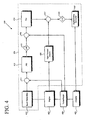
- FIG. 4 illustrates an exemplary engine system 400 according to one embodiment of the invention, according to which a cascaded PID technique is implemented to control the speed of the turbocharger as a means for managing vane position.
- the engine 402, VGT 408, actuator 406, and D/A converter 422 of engine system 400 are respectively equivalent to the engine 102, VGT 108, actuator 106, and D/A converter 122 illustrated in FIG. 1 .
- the engine system 400 also comprises a ECU 404.
- a boost target map 410 of the ECU 404 receives input from the engine 402 indicating the engine speed and/or fuel rate of the engine 402. Based on the fuel rate or engine speed of the engine 402, a boost target is derived from the boost target map 410. The boost target is then compared to the actual boost of the VGT 408 at summing node 411 in order to determine a boost error.
- the boost error is then input into a PID 412, which may utilize any suitable PID technique known in the art to determine a turbo speed target.
- the PID 412 may be configured to produce the turbo speed target using a modified PID approach. According to the modified PID approach, a change in the speed of the turbo, i.e., ⁇ speed , needed to achieve the boost target is first calculated and then summed with the actual turbo speed in order to arrive at a turbo speed target.
- the turbo speed limit may be calculated by summing ⁇ speed with the actual turbo speed.
- a limiting block 413 may next be implemented to limit the turbo speed target to within a desired range.
- Lower and upper turbo speed limits may be set for the system in order to enhance performance while minimizing stress to the system.
- the turbo speed target can be reset to with the desired range at the limiting block 413.
- turbo speed target After the turbo speed target has been determined, it is compared to the actual turbo speed at the summing node 415. The difference between the turbo speed target and the actual turbo speed, which is defined as the turbo speed error, or "err speed ,” is then fed into a PID 414.
- the PID 414 may be configured to determine a new vane position (i.e., ⁇ new ) based on err speed and a known PID technique. Alternatively, the PID 414 may determine ⁇ new by first utilizing a modified PID to calculate a desired change in vane position, i.e.
- ⁇ ⁇ k p err speed + k d err speed / dt
- err speed is the difference between the actual turbo speed and the turbo speed target as determined at a summing node 415
- k p is the proportional gain value
- k d is the differential gain value
- certain embodiments of the engine system 400 may also include a feed forward module 420, which is equivalent to the feed forward module 120 of engine system 100 in FIG. 1 .
- the feed forward module 420 receives input from sensors on the engine 402 indicating the throttle position and/or fuel rate of the engine 402. Based on the input throttle position or fuel rate, a threshold value ("Y") and a constant value ("K a "), the feed forward module 420 generates a feed forward value that is fed into the summing node 417 in order to modify ⁇ new as needed.
- the feed forward value can be calculated according to Equation 2, described above.
- a limiting block 419 maybe implemented as a safeguard to keep ⁇ new within a desired range.
- An upper and lower vane position can be defined, and in instances where ⁇ new is outside these parameters, then ⁇ new can be reset to be within the upper and lower thresholds.
- ⁇ new is fed into a D/A converter 422, which converts ⁇ new into an analog signal for the controlling actuator 406.
- the actuator 406 adjusts the vane position of the VGT 408 to match ⁇ new . In this manner, the vane position of the VGT 408 can be controlled and adjusted.
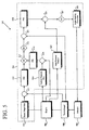
- FIG. 5 illustrates an engine system 500 in accordance with one embodiment, according to which a closed loop engine braking control based on turbine pressure, combined with a cascaded PID technique, is utilized to manage vane position.
- the engine 502, VGT 508, actuator 506, and D/A converter 522 of the engine system 500 are respectively equivalent to the engine 102, VGT 108, actuator 106, and D/A converter 122 of the system 100 illustrated in FIG. 1 .
- an ECU 504 first determines a turbo speed target for the VGT 508 according to two methods.
- a boost target map 510 determines a boost target based on the engine speed and fuel rate of the engine 502.
- the boost target is then compared to the actual boost of the VGT 508 at a summing node 511 to derive the boost error.
- the boost error is input into a PID 512, which can utilize a conventional PID technique to generate a turbo speed target based on the boost error.
- the turbo speed target may be calculated by summing ⁇ speed with the actual turbo speed.
- the engine speed of the engine 502 is fed into a turbine pressure map 514.
- the turbine pressure map 514 can be a file stored in a memory component of the ECU 504, for example, mapping desired turbine pressures for a given engine speeds.
- a turbine pressure target is determined from the turbine pressure map 514.
- the turbine pressure target is then compared to the actual turbine pressure, as measured by sensors on the engine 502.
- the turbine pressure error which is referred to as the difference between the turbine pressure target and the actual turbine pressure, is determined by comparing the turbine pressure target and the actual turbine pressure at summing node 515.
- the turbine pressure error is then input into a PID 516, which can generate a turbo speed target utilizing a conventional PID technique.
- a modified PID technique may instead be used to arrive at the turbo speed target by first determining a desired change in turbo speed, or ⁇ speed , and then adding the ⁇ speed to the actual turbo speed.
- the ECU 504 determines whether the engine 502 is in power or braking mode. If the engine 502 is in a power mode, then the turbo speed target generated by the first method (i.e., by PID 512) is selected to establish new vane position for the current iteration. On the other had, if the engine 502 is in braking mode, then the turbo speed target generated according to the second method (i.e., by PID 516) is selected. It is noted that the turbo speed target selected at decision block 517 is also referred to as a "selected turbo speed target," in the present application.
- the turbo speed target selected at the decision block 517 may be limited to within a desired range of turbo speeds at a limiting block 519, where, if the turbo speed target falls outside the desired range, the turbo speed target can be reset to be within the desired range.
- the turbo speed target is then compared to the actual turbo speed at a summing node 521 to determine a turbo speed error, or "err speed ,” which is fed into a PID 518.
- the PID 518 may be configured to determine a new vane position (i.e., ⁇ new ) based on err speed and a known PID technique. Alternatively, the PID 518 may determine ⁇ new by first utilizing a modified PID to calculate a desired change in vane position, i.e.
- ⁇ ⁇ k p err speed + k d err speed / dt
- err speed is the error value defined as the difference between the actual turbo speed and the turbo speed target as determined at the summing node 521
- k p is the proportional gain value
- k d is the differential gain value
- ⁇ ⁇ is summed with the vane position from the preceding iteration to arrive at ⁇ new , which is then inputted into a summing node 523.
- a feed forward module 520 may be implemented to improve control of the vane position.
- the feed forward module 520 receives input from sensors on the engine 502 indicating the throttle position and/or fuel rate of the engine 502.
- the forward module 520 can be configured to generate a feed forward value based on the inputted throttle position or fuel rate, a threshold value ("Y") and a constant value ("K a ").
- the feed forward value may then be input into the summing node 523 in order to modify ⁇ new as may be needed.
- the feed forward value can be calculated according to Equation 2, described above.
- a limiting block 525 may be included in the ECU 504 to ensure that ⁇ new is within a desired range of vane positions. If ⁇ new does not fall within the desired range, then ⁇ new may be reset at the limiting block 525 so as to be within the desired range. ⁇ new is then fed into a D/A converter 522, which converts ⁇ new into an analog signal for controlling the actuator 506. Based on the signal received from the D/A converter 522, the actuator 506 adjusts the vane position of the VGT 508 to match ⁇ new . In this manner, the vane position of the VGT 508 can be controlled and adjusted.
Landscapes
- Engineering & Computer Science (AREA)
- Mechanical Engineering (AREA)
- General Engineering & Computer Science (AREA)
- Chemical & Material Sciences (AREA)
- Combustion & Propulsion (AREA)
- Supercharger (AREA)
Claims (10)
- Procédé de positionnement d'un élément à géométrie variable disposé à l'intérieur d'un turbocompresseur (508) qui est accouplé à un moteur à combustion interne (502), ledit procédé comprenant les étapes suivantes :Détermination (206) d'un objectif de pression de suralimentation pour ledit turbocompresseur ;Calcul (210) d'une première valeur d'erreur, errboost, entre ledit objectif de pression de suralimentation et une pression de suralimentation réelle mesurée ;Génération d'un premier objectif de vitesse de turbocompresseur pour ledit turbocompresseur en se basant sur ladite errboost ;Détermination d'un objectif de pression de turbine pour ledit turbocompresseur ;Calcul d'une deuxième valeur d'erreur, errturbine, entre ledit objectif de pression de turbine et la pression de turbine réelle mesurée ;Génération d'un deuxième objectif de vitesse de turbocompresseur pour ledit turbocompresseur en se basant sur ladite errturbine ;Sélection dudit premier objectif de vitesse de turbocompresseur lorsque ledit moteur est dans un mode de puissance ou sélection dudit deuxième objectif de vitesse de turbocompresseur lorsque ledit moteur est dans un mode de freinage pour produire une vitesse d'objectif de turbocompresseur choisi ;Calcul d'une troisième valeur d'erreur, errspeed, entre ledit objectif de vitesse de turbocompresseur choisi et une vitesse de turbocompresseur réelle mesurée ;Détermination (212) d'une nouvelle position de l'élément à géométrie variable pour ledit turbocompresseur en se basant sur ladite errspeed ; etPositionnement (222) dudit élément à géométrie variable en fonction de ladite nouvelle position de l'élément à géométrie variable.
- Procédé selon la revendication 1, selon lequel ladite étape de génération dudit premier objectif de vitesse de turbocompresseur comprend les étapes suivantes :Détermination d'une variation dans la vitesse du turbocompresseur, Δspeed, ladite Δspeed étant pour l'essentiel égale à kp (errboost) + kd (errboost)/dt ; etAddition de ladite Δspeed à ladite vitesse de turbocompresseur réelle,kp désignant ici une valeur de gain proportionnel et kd une valeur de gain différentiel.
- Procédé selon la revendication 1, selon lequel ladite étape de génération dudit deuxième objectif de vitesse de turbocompresseur comprend les étapes suivantes :Détermination d'une variation dans la vitesse du turbocompresseur, Δspeed, ladite Δspeed étant pour l'essentiel égale à kp (errturbine) + kd(errturbine)/dt ; etAddition de ladite Δspeed à ladite vitesse de turbocompresseur réelle,kp désignant ici une valeur de gain proportionnel et kd une valeur de gain différentiel.
- Procédé selon la revendication 1, selon lequel ladite étape de détermination de ladite nouvelle position de l'élément à géométrie variable comprend les étapes suivantes :Détermination d'une variation dans la position de l'élément à géométrie variable, Δθ, ladite Δθ étant pour l'essentiel égale à kp (errspeed) + kd (errspeed)/dt ; etAddition de ladite Δθ à une position précédente de l'élément à géométrie variable,kp désignant ici une valeur de gain proportionnel et kd une valeur de gain différentiel.
- Procédé selon la revendication 1, comprenant en outre une étape de modification de ladite nouvelle position de l'élément à géométrie variable avec une valeur d'action directe, FF, ladite FF étant pour l'essentiel égale à (|dTP/dt| - Y) * Ka avant ladite étape de positionnement dudit élément à géométrie variable,
TP désignant ici une position du papillon des gaz, Y une valeur de seuil et Ka une constante. - Système (500) pour positionner un élément à géométrie variable disposé à l'intérieur d'un turbocompresseur (508) qui est accouplé à un moteur à combustion interne (502), ledit système comprenant :un tableau d'objectifs de suralimentation (510) pour déterminer un objectif de pression de suralimentation pour ledit turbocompresseur ;une unité de commande de moteur (511, 515, 517, 521) configurée pour calculer une première valeur d'erreur, errboost, entre ledit objectif de pression de suralimentation et une pression de suralimentation réelle mesurée ;un premier module proportionnel intégral différentiel (512) configuré pour générer un premier objectif de vitesse de turbocompresseur pour ledit turbocompresseur en se basant sur ladite errboost ;un tableau de pression de turbine (514) pour déterminer un objectif de pression de turbine pour ledit turbocompresseur, ladite unité de commande de moteur étant en outre configurée pour calculer une deuxième valeur d'erreur, errturbine, entre ledit objectif de pression de turbine et la pression de turbine réelle mesurée ;un deuxième module proportionnel intégral différentiel (516) configuré pour générer un deuxième objectif de vitesse de turbocompresseur pour ledit turbocompresseur en se basant sur ladite errturbine, ladite unité de commande de moteur étant en outre configurée pour sélectionner ledit premier objectif de vitesse de turbocompresseur lorsque ledit moteur est dans un mode de puissance ou pour sélectionner ledit deuxième objectif de vitesse de turbocompresseur lorsque ledit moteur est dans un mode de freinage pour produire une vitesse d'objectif de turbocompresseur choisi et pour calculer une troisième valeur d'erreur, errspeed, entre ledit objectif de vitesse de turbocompresseur choisi et une vitesse de turbocompresseur réelle mesurée ;un troisième module proportionnel intégral différentiel (518) configuré pour déterminer une nouvelle position de l'élément à géométrie variable pour ledit turbocompresseur en se basant sur ladite errspeed ; etun actionneur (506) configuré pour positionner l'élément à géométrie variable dudit turbocompresseur en fonction de ladite nouvelle position de l'élément à géométrie variable.
- Système selon la revendication 6, avec lequel ledit premier module proportionnel intégral différentiel (512) génère ledit premier objectif de vitesse de turbocompresseur en déterminant une variation dans la vitesse du turbocompresseur, Δspeed, ladite Δspeed étant pour l'essentiel égale à kp (errboost) + kd (errboost)/dt, et en additionnant ladite Δspeed à ladite vitesse de turbocompresseur réelle, kp désignant ici une valeur de gain proportionnel et kd une valeur de gain différentiel.
- Système selon la revendication 6, avec lequel ledit deuxième module proportionnel intégral différentiel (516) génère ledit deuxième objectif de vitesse de turbocompresseur en déterminant une variation dans la vitesse du turbocompresseur, Δspeed, ladite Δspeed étant pour l'essentiel égale à kp (errturbine) + kd (errturbine)/dt, et en additionnant ladite Δspeed à ladite vitesse de turbocompresseur réelle, kp désignant ici une valeur de gain proportionnel et kd une valeur de gain différentiel.
- Système selon la revendication 6, avec lequel ledit troisième module proportionnel intégral différentiel (518) détermine ladite nouvelle position de l'élément à géométrie variable en déterminant une variation dans la position de l'élément à géométrie variable, Δθ, ladite Δθ étant pour l'essentiel égale à kp (errspeed) + kd (errspeed)/dt, et en additionnant ladite Δθ à une position précédente de l'élément à géométrie variable, kp désignant ici une valeur de gain proportionnel et kd une valeur de gain différentiel.
- Système selon la revendication 6, comprenant en plus un module à action directe configuré pour générer une valeur d'action directe, FF, ladite FF étant pour l'essentiel égale à (|dTP/dt| - Y) * Ka, ladite FF étant utilisée pour modifier ladite première nouvelle position de pale, TP étant une position du papillon des gaz, Y étant une valeur de seuil et Ka étant une constante.
Applications Claiming Priority (2)
| Application Number | Priority Date | Filing Date | Title |
|---|---|---|---|
| US10/199,519 US6681573B2 (en) | 2002-02-05 | 2002-07-19 | Methods and systems for variable geometry turbocharger control |
| EP03766033A EP1529159B1 (fr) | 2002-07-19 | 2003-07-21 | Procedes et systemes de commande d'un turbocompresseur a geometrie variable |
Related Parent Applications (2)
| Application Number | Title | Priority Date | Filing Date |
|---|---|---|---|
| EP03766033.9 Division | 2003-07-21 | ||
| EP03766033A Division EP1529159B1 (fr) | 2002-07-19 | 2003-07-21 | Procedes et systemes de commande d'un turbocompresseur a geometrie variable |
Publications (3)
| Publication Number | Publication Date |
|---|---|
| EP1801384A2 EP1801384A2 (fr) | 2007-06-27 |
| EP1801384A3 EP1801384A3 (fr) | 2009-01-14 |
| EP1801384B1 true EP1801384B1 (fr) | 2011-10-12 |
Family
ID=30769493
Family Applications (3)
| Application Number | Title | Priority Date | Filing Date |
|---|---|---|---|
| EP03766033A Expired - Fee Related EP1529159B1 (fr) | 2002-07-19 | 2003-07-21 | Procedes et systemes de commande d'un turbocompresseur a geometrie variable |
| EP07101997A Expired - Fee Related EP1801384B1 (fr) | 2002-07-19 | 2003-07-21 | Procédés et systèmes de contrôle du turbocompresseur à géométrie variable |
| EP07102000A Withdrawn EP1801385A3 (fr) | 2002-07-19 | 2003-07-21 | Procédés et systèmes de contrôle du turbocompresseur à géométrie variable |
Family Applications Before (1)
| Application Number | Title | Priority Date | Filing Date |
|---|---|---|---|
| EP03766033A Expired - Fee Related EP1529159B1 (fr) | 2002-07-19 | 2003-07-21 | Procedes et systemes de commande d'un turbocompresseur a geometrie variable |
Family Applications After (1)
| Application Number | Title | Priority Date | Filing Date |
|---|---|---|---|
| EP07102000A Withdrawn EP1801385A3 (fr) | 2002-07-19 | 2003-07-21 | Procédés et systèmes de contrôle du turbocompresseur à géométrie variable |
Country Status (4)
| Country | Link |
|---|---|
| US (1) | US6681573B2 (fr) |
| EP (3) | EP1529159B1 (fr) |
| AU (1) | AU2003254191A1 (fr) |
| WO (1) | WO2004009976A1 (fr) |
Families Citing this family (45)
| Publication number | Priority date | Publication date | Assignee | Title |
|---|---|---|---|---|
| US6928817B2 (en) * | 2002-06-28 | 2005-08-16 | Honeywell International, Inc. | Control system for improved transient response in a variable-geometry turbocharger |
| US6899090B2 (en) * | 2002-08-21 | 2005-05-31 | Honeywell International, Inc. | Dual path EGR system and methods |
| DE10340816A1 (de) * | 2003-09-04 | 2005-03-31 | Robert Bosch Gmbh | Verfahren und Vorrichtung zum Betreiben einer Brennkraftmaschine |
| US7013879B2 (en) * | 2003-11-17 | 2006-03-21 | Honeywell International, Inc. | Dual and hybrid EGR systems for use with turbocharged engine |
| US7007472B2 (en) * | 2004-02-10 | 2006-03-07 | Cummins, Inc. | System for limiting turbocharger rotational speed |
| US6895751B1 (en) * | 2004-03-08 | 2005-05-24 | Christopher Greentree | Vane control |
| US7124582B2 (en) * | 2004-07-26 | 2006-10-24 | International Engine Intellectual Property Company, Llc | Method and apparatus for determining turbocharger boost |
| US7014418B1 (en) | 2004-12-03 | 2006-03-21 | Honeywell International, Inc. | Multi-stage compressor and housing therefor |
| DE102004061454A1 (de) | 2004-12-17 | 2006-06-29 | Delphi Technologies, Inc., Troy | Verfahren und Vorrichtung zur Motorsteuerung bei einem Kraftfahrzeug |
| US7882702B2 (en) * | 2004-12-30 | 2011-02-08 | Gm Global Technology Operations, Inc. | Control system to minimize white smoke using variable nozzle turbo |
| DE102005015609B4 (de) * | 2005-04-05 | 2008-01-17 | Siemens Ag | Vorrichtung zum Steuern einer Brennkraftmaschine |
| JP4365342B2 (ja) * | 2005-04-08 | 2009-11-18 | トヨタ自動車株式会社 | ターボチャージャの異常判定装置 |
| US7137773B1 (en) * | 2005-05-16 | 2006-11-21 | Gm Global Technology Operations, Inc. | Model-based statistical process to determine diagnostic limits in a sensor position system for a turbocharger |
| FR2888884B1 (fr) * | 2005-07-19 | 2007-09-21 | Renault Sas | Procede et systeme de controle de la suralimentation en air d'un moteur a combustion interne de vehicule automobile |
| US7866159B2 (en) * | 2005-10-18 | 2011-01-11 | Rolls-Royce Corporation | Variable geometry hysteresis control for a gas turbine engine |
| DE102005054524A1 (de) * | 2005-11-14 | 2007-05-16 | Porsche Ag | Verfahren und Steuergerät zur Steuerung eines Turboladers mit steuerbarem Turbinen-Strömungsquerschnitt |
| FR2898642B1 (fr) * | 2006-03-14 | 2008-05-16 | Renault Sas | Procede de commande d'un moteur suralimente comportant un diagnostic de regulation |
| DE102006032835B4 (de) * | 2006-07-14 | 2011-01-27 | Audi Ag | Verfahren und Vorrichtung zur Ladedruckregelung einer Brennkraftmaschine |
| US20080078176A1 (en) * | 2006-10-02 | 2008-04-03 | International Engine Intellectual Property Company | Strategy for control of recirculated exhaust gas to null turbocharger boost error |
| US7644584B2 (en) * | 2006-11-30 | 2010-01-12 | Caterpillar Inc. | Method for modulating turbocharger braking |
| DE102007013251B4 (de) * | 2007-03-20 | 2019-08-29 | Robert Bosch Gmbh | Verfahren und Vorrichtung zur Überwachung eines Abgasturboladers einer Brennkraftmaschine |
| US8151567B2 (en) * | 2007-05-29 | 2012-04-10 | Ford Global Technologies, Llc | Adaptive learning system and method of vane position for a variable geometry turbocharger |
| US7937996B2 (en) * | 2007-08-24 | 2011-05-10 | GM Global Technology Operations LLC | Turbo speed sensor diagnostic for turbocharged engines |
| US7650218B2 (en) * | 2007-09-20 | 2010-01-19 | Cummins Ip, Inc | Apparatus, system, and method for preventing turbocharger overspeed in a combustion engine |
| US8523511B2 (en) * | 2007-11-13 | 2013-09-03 | Honeywell International Inc. | Adaptive variable geometry turbocharger strategy |
| JP2009221881A (ja) * | 2008-03-13 | 2009-10-01 | Yanmar Co Ltd | エンジン |
| GB2461553B (en) * | 2008-07-03 | 2012-10-10 | Gm Global Tech Operations Inc | A control method and system for a fluid control device, based on position sensor learning |
| JP5164737B2 (ja) * | 2008-08-19 | 2013-03-21 | ヤンマー株式会社 | エンジン |
| US8585353B2 (en) * | 2009-08-30 | 2013-11-19 | Steven Don Arnold | Variable volute turbine |
| FR2955613B1 (fr) * | 2010-01-28 | 2012-07-13 | Peugeot Citroen Automobiles Sa | Procede de regulation de la pression de suralimentation d'un moteur thermique |
| FR2963389B1 (fr) * | 2010-07-28 | 2012-08-17 | Renault Sas | Procede de diagnostic d'un dysfonctionnement de la suralimentation d'un moteur a combustion interne |
| FR2974392B1 (fr) * | 2011-04-21 | 2013-05-10 | Renault Sa | Procede de diagnostic de defaillance d'un moteur suralimente et moteur suralimente |
| CN103857896B (zh) | 2011-10-06 | 2016-08-17 | 丰田自动车株式会社 | 内燃机的控制装置 |
| US9291093B2 (en) * | 2013-02-08 | 2016-03-22 | GM Global Technology Operations LLC | Turbocharger flow control |
| JP6294646B2 (ja) | 2013-12-04 | 2018-03-14 | 三菱重工業株式会社 | ターボコンパウンドシステムの制御装置 |
| JP6377340B2 (ja) | 2013-12-04 | 2018-08-22 | 三菱重工業株式会社 | 過給システムの制御装置 |
| JP6351962B2 (ja) | 2013-12-04 | 2018-07-04 | 三菱重工業株式会社 | ターボチャージャの制御装置 |
| JP6234198B2 (ja) | 2013-12-04 | 2017-11-22 | 三菱重工業株式会社 | ターボチャージャ装置 |
| JP6434285B2 (ja) * | 2013-12-04 | 2018-12-05 | 三菱重工業株式会社 | 過給システムの制御装置 |
| KR102214409B1 (ko) * | 2014-04-29 | 2021-02-18 | 두산인프라코어 주식회사 | 엔진 시스템의 제어 장치 및 제어 방법 |
| AT517033B1 (de) * | 2015-03-30 | 2018-06-15 | Avl List Gmbh | Verfahren zur regelung des betriebspunktes einer abgasturbine |
| EP3523527B2 (fr) * | 2016-10-06 | 2023-11-29 | Volvo Truck Corporation | Procédé de commande de couple de freinage du moteur |
| US11391223B2 (en) * | 2020-08-19 | 2022-07-19 | Caterpillar Inc. | Increasing braking power and exhaust gas temperature |
| WO2022087546A1 (fr) * | 2020-10-22 | 2022-04-28 | Tula Technology, Inc. | Désactivation de cylindre de décélération et gestion de vitesse de rotation de turbocompresseur |
| FR3119867A1 (fr) * | 2021-02-17 | 2022-08-19 | Psa Automobiles Sa | Procede de compensation de dispersions et de derives d'un systeme de suralimentation muni d'un turbocompresseur a geometrie variable |
Family Cites Families (23)
| Publication number | Priority date | Publication date | Assignee | Title |
|---|---|---|---|---|
| US642A (en) | 1838-03-17 | Machine foe crimping | ||
| US6269A (en) | 1849-04-03 | Cast-iron car-wheel | ||
| US6161384A (en) | 1994-05-02 | 2000-12-19 | Waukesha Engine Division, Dresser Equipment Group, Inc. | Turbocharger control management system throttle reserve control |
| US5551236A (en) | 1994-05-02 | 1996-09-03 | Dresser Industries, Inc. | Turbocharger control management system |
| US6256993B1 (en) | 1995-07-28 | 2001-07-10 | Honeywell International, Inc. | Motor-assisted variable geometry turbocharging system |
| IT1284345B1 (it) | 1996-01-26 | 1998-05-18 | Fiat Ricerche | Metodo e unita' di controllo della pressione di sovralimentazione per un motore turbodiesel con turbina a geometria variabile |
| JP3237565B2 (ja) | 1997-04-02 | 2001-12-10 | 三菱自動車工業株式会社 | 過給機制御装置 |
| DE19715236B4 (de) | 1997-04-12 | 2005-03-03 | Daimlerchrysler Ag | Verfahren zur Steuerung des Ladeluftmassenstroms einer Brennkraftmaschine mit einem Abgasturbolader mit verstellbarer Turbinengeometrie |
| US6000221A (en) | 1997-11-04 | 1999-12-14 | Detroit Diesel Corporation | System for controlling a variable geometry turbocharger |
| DE19750445C1 (de) | 1997-11-14 | 1999-06-24 | Daimler Chrysler Ag | Verfahren zur Steuerung eines VTG-Abgasturboladers |
| DE19751977C2 (de) | 1997-11-25 | 2001-02-01 | Daimler Chrysler Ag | Steuerung für den Ladedruck einer aufgeladenen Brennkraftmaschine |
| DE19757661C1 (de) | 1997-12-23 | 1999-03-04 | Siemens Ag | Verfahren für die Ladedruckregelung einer Brennkraftmaschine mit Turbolader |
| GB9800282D0 (en) | 1998-01-08 | 1998-03-04 | Rolls Royce Cars Limited | Turbocharger system |
| DE19844213C1 (de) * | 1998-09-26 | 1999-05-27 | Daimler Chrysler Ag | Verfahren zur Regelung oder Steuerung einer aufgeladenen Brennkraftmaschine |
| US6272859B1 (en) * | 1998-10-02 | 2001-08-14 | Caterpillar Inc. | Device for controlling a variable geometry turbocharger |
| US6269642B1 (en) | 1998-10-05 | 2001-08-07 | Alliedsignal Inc. | Variable geometry turbocharger |
| DE19858293C1 (de) | 1998-12-17 | 2000-03-09 | Daimler Chrysler Ag | Brennkraftmaschine mit einem Abgasturbolader mit variabler Turbinengeometrie |
| US6067800A (en) | 1999-01-26 | 2000-05-30 | Ford Global Technologies, Inc. | Control method for a variable geometry turbocharger in a diesel engine having exhaust gas recirculation |
| DE19961613A1 (de) | 1999-12-21 | 2001-07-19 | Daimler Chrysler Ag | Abgasturbine eines Abgasturboladers für eine Brennkraftmaschine |
| US6418719B2 (en) * | 2000-01-25 | 2002-07-16 | International Engine Intellectual Property Company, L.L.C. | Control of a variable geometry turbocharger by sensing exhaust pressure |
| US6427445B1 (en) * | 2000-02-10 | 2002-08-06 | International Engine Intellectual Property Company, L.L.C. | Variable nozzle turbine control strategy |
| EP1550800B1 (fr) | 2000-03-31 | 2007-11-14 | Detroit Diesel Corporation | Procédé de commande d'un moteur à combustion interne |
| ITTO20010041A1 (it) | 2001-01-19 | 2002-07-19 | Iveco Motorenforschung Ag | Sistema di controllo per turbocompressore a geometria variabile. |
-
2002
- 2002-07-19 US US10/199,519 patent/US6681573B2/en not_active Expired - Lifetime
-
2003
- 2003-07-21 WO PCT/US2003/023379 patent/WO2004009976A1/fr not_active Application Discontinuation
- 2003-07-21 EP EP03766033A patent/EP1529159B1/fr not_active Expired - Fee Related
- 2003-07-21 AU AU2003254191A patent/AU2003254191A1/en not_active Abandoned
- 2003-07-21 EP EP07101997A patent/EP1801384B1/fr not_active Expired - Fee Related
- 2003-07-21 EP EP07102000A patent/EP1801385A3/fr not_active Withdrawn
Also Published As
| Publication number | Publication date |
|---|---|
| EP1529159B1 (fr) | 2011-05-11 |
| US20030145591A1 (en) | 2003-08-07 |
| EP1801385A3 (fr) | 2009-01-14 |
| EP1801384A3 (fr) | 2009-01-14 |
| EP1801385A2 (fr) | 2007-06-27 |
| EP1801384A2 (fr) | 2007-06-27 |
| WO2004009976A1 (fr) | 2004-01-29 |
| AU2003254191A1 (en) | 2004-02-09 |
| EP1529159A1 (fr) | 2005-05-11 |
| US6681573B2 (en) | 2004-01-27 |
Similar Documents
| Publication | Publication Date | Title |
|---|---|---|
| EP1801384B1 (fr) | Procédés et systèmes de contrôle du turbocompresseur à géométrie variable | |
| EP1474597B1 (fr) | Procede decommande de turbocompresseur a geometrie variable et systeme associe | |
| US6637205B1 (en) | Electric assist and variable geometry turbocharger | |
| US6662562B2 (en) | Method and device for regulating the boost pressure of an internal combustion engine | |
| US7540148B2 (en) | Method and device for operating at least one turbocharger on an internal combustion engine | |
| US7556473B2 (en) | Control unit for compressor | |
| RU2414618C2 (ru) | Способ и устройство контроля наддува воздуха в двигателе внутреннего сгорания | |
| JPH0232457B2 (fr) | ||
| JP3733281B2 (ja) | 内燃機関の過給圧制御装置および過給圧制御方法 | |
| JP2008510922A (ja) | 内燃機関の給気圧力の制御方法および装置 | |
| US9206746B2 (en) | Method of controlling speed transients in a turbine engine | |
| US6996986B2 (en) | Control system for variable geometry turbocharger | |
| CN110714844B (zh) | 用于控制增压系统的方法 | |
| JP4024423B2 (ja) | ターボチャージャ付内燃機関の燃料噴射量制御装置 | |
| JP4328734B2 (ja) | 可変ベーン式ターボチャージャの制御装置 | |
| JPH02227522A (ja) | 過給圧制御装置 | |
| JPH0535251B2 (fr) | ||
| JP4468874B2 (ja) | 内燃機関の過給圧制御装置および過給圧制御方法 | |
| EP1302644A1 (fr) | Procédé pour la commande d'un turbocompresseur avec une turbine à géométrie variable | |
| JPH0874588A (ja) | 過給圧制御方法 | |
| CN100429390C (zh) | 用于改进可变几何形状涡轮增压器中的瞬态响应的控制系统 | |
| JPS6050969B2 (ja) | 二軸ガスタ−ビンのバリアブルベ−ン制御装置 | |
| JPS5823233A (ja) | ガスタ−ビンの加減速性能補償回路 | |
| JPH02115526A (ja) | エンジンの過給圧制御装置 | |
| JP2016102426A (ja) | 多段過給システム |
Legal Events
| Date | Code | Title | Description |
|---|---|---|---|
| PUAI | Public reference made under article 153(3) epc to a published international application that has entered the european phase |
Free format text: ORIGINAL CODE: 0009012 |
|
| AC | Divisional application: reference to earlier application |
Ref document number: 1529159 Country of ref document: EP Kind code of ref document: P |
|
| AK | Designated contracting states |
Kind code of ref document: A2 Designated state(s): DE FR GB SE |
|
| PUAL | Search report despatched |
Free format text: ORIGINAL CODE: 0009013 |
|
| AK | Designated contracting states |
Kind code of ref document: A3 Designated state(s): DE FR GB SE |
|
| 17P | Request for examination filed |
Effective date: 20090713 |
|
| 17Q | First examination report despatched |
Effective date: 20090814 |
|
| AKX | Designation fees paid |
Designated state(s): DE FR GB |
|
| GRAP | Despatch of communication of intention to grant a patent |
Free format text: ORIGINAL CODE: EPIDOSNIGR1 |
|
| GRAS | Grant fee paid |
Free format text: ORIGINAL CODE: EPIDOSNIGR3 |
|
| GRAA | (expected) grant |
Free format text: ORIGINAL CODE: 0009210 |
|
| AC | Divisional application: reference to earlier application |
Ref document number: 1529159 Country of ref document: EP Kind code of ref document: P |
|
| AK | Designated contracting states |
Kind code of ref document: B1 Designated state(s): DE FR GB |
|
| REG | Reference to a national code |
Ref country code: GB Ref legal event code: FG4D |
|
| REG | Reference to a national code |
Ref country code: DE Ref legal event code: R096 Ref document number: 60338783 Country of ref document: DE Effective date: 20111215 |
|
| PLBE | No opposition filed within time limit |
Free format text: ORIGINAL CODE: 0009261 |
|
| STAA | Information on the status of an ep patent application or granted ep patent |
Free format text: STATUS: NO OPPOSITION FILED WITHIN TIME LIMIT |
|
| 26N | No opposition filed |
Effective date: 20120713 |
|
| REG | Reference to a national code |
Ref country code: DE Ref legal event code: R097 Ref document number: 60338783 Country of ref document: DE Effective date: 20120713 |
|
| REG | Reference to a national code |
Ref country code: FR Ref legal event code: PLFP Year of fee payment: 14 |
|
| REG | Reference to a national code |
Ref country code: FR Ref legal event code: PLFP Year of fee payment: 15 |
|
| REG | Reference to a national code |
Ref country code: FR Ref legal event code: PLFP Year of fee payment: 16 |
|
| REG | Reference to a national code |
Ref country code: DE Ref legal event code: R081 Ref document number: 60338783 Country of ref document: DE Owner name: GARRETT TRANSPORTATION I INC., TORRANCE, US Free format text: FORMER OWNER: HONEYWELL INC., MORRISTOWN, N.J., US |
|
| REG | Reference to a national code |
Ref country code: GB Ref legal event code: 732E Free format text: REGISTERED BETWEEN 20190725 AND 20190731 |
|
| PGFP | Annual fee paid to national office [announced via postgrant information from national office to epo] |
Ref country code: DE Payment date: 20190731 Year of fee payment: 17 Ref country code: FR Payment date: 20190725 Year of fee payment: 17 |
|
| PGFP | Annual fee paid to national office [announced via postgrant information from national office to epo] |
Ref country code: GB Payment date: 20190729 Year of fee payment: 17 |
|
| REG | Reference to a national code |
Ref country code: DE Ref legal event code: R119 Ref document number: 60338783 Country of ref document: DE |
|
| GBPC | Gb: european patent ceased through non-payment of renewal fee |
Effective date: 20200721 |
|
| PG25 | Lapsed in a contracting state [announced via postgrant information from national office to epo] |
Ref country code: FR Free format text: LAPSE BECAUSE OF NON-PAYMENT OF DUE FEES Effective date: 20200731 Ref country code: GB Free format text: LAPSE BECAUSE OF NON-PAYMENT OF DUE FEES Effective date: 20200721 |
|
| PG25 | Lapsed in a contracting state [announced via postgrant information from national office to epo] |
Ref country code: DE Free format text: LAPSE BECAUSE OF NON-PAYMENT OF DUE FEES Effective date: 20210202 |