EP1801323A1 - Befestigungsvorrichtung eines Stabes auf einem Pfosten - Google Patents
Befestigungsvorrichtung eines Stabes auf einem Pfosten Download PDFInfo
- Publication number
- EP1801323A1 EP1801323A1 EP06026643A EP06026643A EP1801323A1 EP 1801323 A1 EP1801323 A1 EP 1801323A1 EP 06026643 A EP06026643 A EP 06026643A EP 06026643 A EP06026643 A EP 06026643A EP 1801323 A1 EP1801323 A1 EP 1801323A1
- Authority
- EP
- European Patent Office
- Prior art keywords
- clamping means
- pole
- wall
- locking pin
- fastening device
- Prior art date
- Legal status (The legal status is an assumption and is not a legal conclusion. Google has not performed a legal analysis and makes no representation as to the accuracy of the status listed.)
- Granted
Links
Images


Classifications
-
- E—FIXED CONSTRUCTIONS
- E04—BUILDING
- E04H—BUILDINGS OR LIKE STRUCTURES FOR PARTICULAR PURPOSES; SWIMMING OR SPLASH BATHS OR POOLS; MASTS; FENCING; TENTS OR CANOPIES, IN GENERAL
- E04H17/00—Fencing, e.g. fences, enclosures, corrals
- E04H17/14—Fences constructed of rigid elements, e.g. with additional wire fillings or with posts
- E04H17/1413—Post-and-rail fences, e.g. without vertical cross-members
- E04H17/1447—Details of connections between rails and posts
-
- E—FIXED CONSTRUCTIONS
- E04—BUILDING
- E04H—BUILDINGS OR LIKE STRUCTURES FOR PARTICULAR PURPOSES; SWIMMING OR SPLASH BATHS OR POOLS; MASTS; FENCING; TENTS OR CANOPIES, IN GENERAL
- E04H17/00—Fencing, e.g. fences, enclosures, corrals
- E04H17/14—Fences constructed of rigid elements, e.g. with additional wire fillings or with posts
- E04H17/1413—Post-and-rail fences, e.g. without vertical cross-members
- E04H17/1417—Post-and-rail fences, e.g. without vertical cross-members with vertical cross-members
-
- E—FIXED CONSTRUCTIONS
- E04—BUILDING
- E04H—BUILDINGS OR LIKE STRUCTURES FOR PARTICULAR PURPOSES; SWIMMING OR SPLASH BATHS OR POOLS; MASTS; FENCING; TENTS OR CANOPIES, IN GENERAL
- E04H17/00—Fencing, e.g. fences, enclosures, corrals
- E04H17/14—Fences constructed of rigid elements, e.g. with additional wire fillings or with posts
- E04H17/1413—Post-and-rail fences, e.g. without vertical cross-members
- E04H17/1447—Details of connections between rails and posts
- E04H17/1452—Details of connections between rails and posts the ends of the rails are fixed on the lateral sides of the posts
Definitions
- the present invention relates to a device for attaching a rail to a pole, and a barrier comprising such fasteners.
- the invention finds application in the field of fences.
- a fence comprising vertical posts and barred panels.
- Each barred panel extends between two consecutive posts and consists of at least one lower rail and at least one upper rail between which are arranged bars which extend between one of the lower rail and one of upper smooth.
- the placement of the panels on the posts is done by fixing the rails on the poles.
- the fixing of each rail is achieved by their welding or screwing on the posts.
- Welding has the disadvantage of being long and dangerous for the technician performing the welding, and unsightly due to the presence of beads at the welds.
- the screwing has the disadvantage of being visible and sometimes easily removable for a person wishing to cross the fence.
- An object of the present invention is to provide a device for attaching a rail to a pole which does not have the drawbacks of the prior art and which in particular allows a simple fixing, fast and not easily removable of the rail.
- At least one of the clamping means is compressible.
- the means for stressing the locking pin in the bottom of the locking groove comprise the compressible clamping means or means.
- the second clamping means comprises a ramp designed to cooperate with the locking pin during the transition from the free position to the fixed and locked position.
- the ramp extends from below the bottom of the groove to beyond the bottom of the locking groove.
- the first clamping means comprises a head which fits into the hole of the column wall and an axis which extends in the direction of the second clamping means and on which is arranged the pin of blocking.
- the second clamping means comprises a rotation cylinder in which the axis of the first clamping means is inserted and on which the locking groove is made.
- the passage from the free position to the fixed and locked position is effected by rotation of the axis of the first clamping means inside the rotation cylinder.
- the operating means comprise a maneuvering hole made in the first clamping means and an access window made in the second clamping means and allowing access to the operating hole from outside the second clamping means.
- the locking pin and the locking groove are disposed inside the rail when the latter is in position.
- the invention also proposes a barrier comprising at least one fixing device according to one of the preceding objects.
- Fig. 1 shows a fastening device 100 of a rail 136 on a post 134.
- the post 134 extends vertically and consists of a hollow shell whose wall is traversed by a plurality of holes 138.
- the arm 136 extends horizontally and takes, here, the shape of a hollow cylindrical tube.
- an upper rail 136a is integral with a lower rail 136b and between these two rails 136a and 136b extend bars 804.
- This set of two smooth 136a and 136b and 804 bars form a barricaded grid which is fixed between two consecutive columns 134a and 134b.
- the posts 134a and 134b and the barred grids then form a barrier 802 for limiting a space.
- the first clamping means comprises a head 104 integral with an axis 114 on which is disposed a locking pin 118.
- the head 104 is provided for insertion into one of the holes 138 and the axis 114 is extends in the direction of the second clamping means.
- the second clamping means comprises, inter alia, an elastic means 102 and a body 106 in which a rotation cylinder 112 is formed (see Figs 3 to 7).
- the axis 114 of the first clamping means is housed in the rotation cylinder 112 on which is made a locking groove 126.
- the adjustment between the rotation cylinder 112 and the axis 114 is preferably of the sliding type just .
- the elastic means 102 here takes the form of a truncated cone provided with a central bore to allow the passage of the axis 114.
- the elastic means 102 may be for example a truncated cone rubber or a spring of compression with a very high coefficient of stiffness.
- the elastic means 102 and thus the second clamping means are compressible, that is to say that it is possible to compress them and any compression induces the creation of an opposing thrust force.
- this thrust force is used to constrain the locking pin 118 in the bottom of the groove 126, as shown in FIG. 5.
- the base of the truncated cone 102 is engaged in the body 106.
- the elastic means 102 comprises a bore into which a cylindrical protrusion of the elastic means 102 penetrates. This is best seen on the Fig. 7, the vertex 128 of the truncated cone 102 comes into contact with the outside of the wall of the pole 134.
- the assembly of the fixing device 100 is as follows: the head-free end of the shaft 114 is inserted into the elastic means 102, then into the body 106. The locking pin 118 is then inserted into the bore of the axis 114, so as to avoid any disassembly of the fixing device 100.
- the head 104 is not integral with the axis 114 but the locking pin 118 is integral with the axis 114.
- the assembly of the fixing device 100 is then the following the headless end of the shaft 114 is inserted into the body 106, then into the elastic means 102.
- the locking pin 118 is then positioned against the rotation cylinder 112 and the head 104 is then fixed to the end of the axis 114, so as to avoid any disassembly of the fixing device 100.
- Fig. 2 shows the fixing device 100 when assembled.
- the body 106 and the elastic means 102 are then placed between the head 104 and the pin 118.
- Fig. 3 shows a cut-away view of the fixing device 100 when it is in the free position, that is to say when it can be freely mounted in one of the holes 138 of the post 134.
- the first clamping means and the second clamping means then exert no clamping force on the wall of the pole 134.
- the body 106 comprises from outside to inside, an outer cylinder 130, an alignment cylinder 132 and the rotation cylinder 112. These three cylinders form a one-piece assembly.
- the outer cylinder 130 and the alignment cylinder 132 are spaced apart from each other so as to leave free a space 110 forming a cylinder whose dimensions are chosen so as to allow the insertion of the beam 136 and which constitutes the means for holding the stringer 136.
- the external dimensions of the alignment cylinder 132 are slightly smaller than the internal dimensions of the stringer 136 and the internal dimensions of the outer cylinder 130 are slightly greater than the external dimensions of the stringer 136.
- the guide curve of the outer cylinder 130, the guide curve of the alignment cylinder 132, the directional curve of the space 110, the guide curve of the rail 136 and the guide curve of the protrusion of the elastic means 102 are ellipses, which avoids, on the one hand, the rotation of the smooth 136 in the space 110, and, on the other hand, the rotation of the elastic means 102 in the body 106.
- the rotation cylinder 112 extends beyond the outer cylinder 130 and the alignment cylinder 132.
- the wall of the rotation cylinder 112 is machined so as to produce a ramp 124 which extends, in the embodiment described , about a quarter of a turn.
- a first blocking zone consisting of the ramp 124 and the unmachined wall of the rotation cylinder 112
- a second blocking zone which is here constituted by a groove 126.
- the ramp 124 is rising from the first blocking zone to the second blocking zone 126.
- the bottom of the groove 126 is placed below the top of the ramp 124. In other words, the ramp 124 extends from below the bottom of the groove 126 to beyond the bottom of the locking groove 126.
- the free space 110 is disposed outside with respect to the rotation cylinder 112 and the locking groove 126 so that the locking pin 118 and the locking groove 126 are hidden inside the rail 136 and avoid thus unlocking the fixing device 100 by action on the locking pin 118.
- the distance between the head 104 and the mounting bore is such that it must be apparent at the level of the first blocking zone. That is to say, when the elastic means 102 and the body 106 are traversed by the axis 114, the latter is long enough for the locking pin 118 to be inserted into the mounting bore without the elastic means 102 is put in compression.
- the length of the axis 114 must also be sufficient for a space exists between the head 104 and the end 128 of the resilient means 102 facing it. This space allows the insertion of the wall of the pole 134 during the establishment of the fixing device 100 on the pole 134.
- the outer cylinder 130 is pierced with an oblong generally oblong orifice 122 whose axis substantially follows the ramp 124.
- the rotation cylinder 112 is pierced with a guide orifice 120 which has the same general shape .
- the alignment cylinder 132 does not extend to the top of the operating bore 116 and therefore does not need to be pierced with a hole allowing to access the operating bore 116.
- the operating bore 116 and the access window constituted, on the one hand, by the orifice 120 of the rotation cylinder 112 and, on the other hand, by the Guide orifice 122 of the outer cylinder 130 constitute operating means adapted to move the first clamping means and the second clamping means from the free position to the fixed and locked position.
- the access window 120, 122 is thus formed in the second clamping means and allows access to the operating hole 116 from outside the second clamping means.
- the operating bore 116 is dimensioned to allow the insertion of a tool, for example a screwdriver.
- Fig. 4 shows a broken view of the fixing device 100 when in the fixed position but not locked. This position represents an intermediate step between the position of FIG. 3 and the position of FIG. 5 which shows a cutaway view of the fastening device 100 when in the fixed and locked position, that is to say that it can no longer be detached from the pole 134, the first clamping means and the second clamping means. tightening then exerting a clamping force on the wall of the pole 134.
- Fig. 4 shows the fixing device 100 after a tool has been inserted into the operating bore 116 and that this tool has been operated so as to rotate the shaft 114 inside the rotation cylinder 112.
- the tool follows the guide orifices 122, 120.
- the head 104 and the resilient means 102 come together to sandwich the wall of the pole 134.
- the rotation of the axis 114 causes the compression of the elastic means 102 under the effect of the pin of blocking 118 which presses on the ramp 124 thus pushing the body 106 against the wall of the pole 134 while pivoting the head 104.
- the locking pin 118 cooperates with the ramp 124.
- the installation ace of the fixing device 100 is fast because it is achieved by the rotation of the head 104 about a quarter turn and at most one turn.
- Fig. 4 represents an intermediate position in which the locking pin 118 is vis-à-vis the locking groove 126 but before the elastic means 102 has pushed the body 106.
- Fig. 5 represents the final position when the elastic means 102 has pushed the body 106 and thus positioned the locking pin 118 in the locking groove 126.
- the tool When passing from the intermediate position of FIG. 4 at the end position of FIG. 5, the tool remains in the operating bore 116 and follows the movement thereof.
- the elastic means 102 freely pushes the body 106, which has the effect of constraining the locking pin 118 in the bottom of the locking groove 126.
- the transition from the free position to the fixed and locked position s with the constraining of the locking pin 118 in the bottom of the blocking groove 126.
- the constraining of the locking pin 118 in the bottom of the locking groove 126 is performed by means provided for this purpose. effect.
- These means comprise, inter alia, the elastic means 102.
- the establishment of the fixing device 100 is then simple and fast.
- the elastic means 102 must remain sufficiently compressed to ensure the tensioning of the fastening device 100, that is to say that the locking pin 118 must be constrained in the bottom of the locking groove 126.
- the clamping force the wall of the pole 134 between the elastic means 102 and the head 104 must be sufficient to prevent the fixing device 100 from being rotated about its axis and thus releases the head 104 from the hole 138.
- the distance from the head 104 to the locking pin 118 and the depth of the locking groove 126 must remain sufficiently small to ensure that the elastic means remains in compression at the end of the establishment of the fastening device 100.
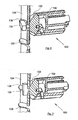
- Fig. 6 shows the fixing device 100 when the head 104 is inserted into one of the holes 138 of the pole 134 and is then in the position shown in FIG. 3.
- Fig. 7 shows the fixing device 100 when the wall of the pole 134 is clamped between the head 104 and the elastic means 102. The fixing device 100 is then in the position shown in FIG. 5.
- the head 104 extends radially relative to the axis 114 and the face of the head 104 which is opposite the wall of the pole 134 has a convex shape, which facilitates the passage of the head 104 behind the wall of the pole 134 and the tightening of the wall of the pole 134 by the head 104 during the rotation of the head 104.
- the passage from the free position (Fig. 6) to the fixed and locked position (Fig. 7) is effected by rotation of the head 104 inside the pole 134 so that the wall of the pole 134 is placed. between the head 104 and the elastic means 102.
- the head 104 is pressed inside the pole 134 and the body 106 is pushed by the locking pin 118 against the outer wall of the 134.
- the displacement of the body 106 causes the elastic means 102 to move against the outer wall of the pole 134.
- the elastic means 102 is thus compressed and deformed to fit the shape of the outer wall of the pole 134, which increases the frictional force between the pole 134 and the elastic means 102 and thus avoids any disassembly of the fastening device 100 by sliding on the wall of the pole 134.
- the locking pin 118 is housed in the locking groove 126, the déformatio n elastic means 102 is reduced but it remains sufficient for the elastic means 102 exerts a clamping force on the wall of the pole 134 in cooperation with the head 104.
- the barrier 802 comprises only a set of posts 134a and 134b and a stringer 136b
- the preceding embodiment can be used by adapting it because there is only one fastener of the first type 100a and a fixing device of the second type 100b.
- the hinges 136 and the fixing devices 100 may be fixed, for example by fitting without play, by riveting or by any other fixing method, eliminating any clearance between the hinges. smooth 136 and fasteners 100.
- the outer cylinder 130, the alignment cylinder 132, the space 110, the beam 136 and the protrusion of the elastic means 102 are more particularly described as cylinders of revolution or elliptical cylinders, but they could take, for example, the shape of a prism.
- the invention has been more particularly described in the case where the locking pin is secured to the first clamping means and the locking groove formed in the second clamping means, but it is possible to switch the respective positions of the pin of blocking and locking groove.
- the second clamping means has been selected as being compressible, but it is possible to choose whether the first clamping means is compressible or both are compressible.
- the means provided for biasing the locking pin in the bottom of the groove may then consist of the first clamping means and / or the second clamping means.
- the orientation of the ramp is not specified because the ramp can be oriented in the direct trigonometric direction or in the indirect trigonometric direction. In the case where there are several ramps, it is possible to predict that some are oriented in the direct trigonometric direction and that others are oriented in the indirect trigonometric direction.
Priority Applications (1)
| Application Number | Priority Date | Filing Date | Title |
|---|---|---|---|
| PL06026643T PL1801323T3 (pl) | 2005-12-23 | 2006-12-22 | Urządzenie do mocowania listew do słupa |
Applications Claiming Priority (1)
| Application Number | Priority Date | Filing Date | Title |
|---|---|---|---|
| FR0513240A FR2895431B1 (fr) | 2005-12-23 | 2005-12-23 | Dispositif de fixation d'une lisse sur un poteau |
Publications (2)
| Publication Number | Publication Date |
|---|---|
| EP1801323A1 true EP1801323A1 (de) | 2007-06-27 |
| EP1801323B1 EP1801323B1 (de) | 2011-07-06 |
Family
ID=37017617
Family Applications (1)
| Application Number | Title | Priority Date | Filing Date |
|---|---|---|---|
| EP06026643A Active EP1801323B1 (de) | 2005-12-23 | 2006-12-22 | Befestigungsvorrichtung eines Stabes auf einem Pfosten |
Country Status (6)
| Country | Link |
|---|---|
| EP (1) | EP1801323B1 (de) |
| CN (1) | CN1987022B (de) |
| AT (1) | ATE515612T1 (de) |
| ES (1) | ES2369631T3 (de) |
| FR (1) | FR2895431B1 (de) |
| PL (1) | PL1801323T3 (de) |
Cited By (5)
| Publication number | Priority date | Publication date | Assignee | Title |
|---|---|---|---|---|
| WO2008122291A1 (fr) * | 2007-03-05 | 2008-10-16 | Dirickx Groupe S.A. | Dispositif de fixation d'une lisse sur un poteau |
| EP1988236B1 (de) * | 2007-05-03 | 2011-04-13 | Dirickx Groupe | Vorrichtung zum Befestigen einer Pfette auf einem Pfosten |
| AU2016101046B4 (en) * | 2016-07-08 | 2017-04-20 | Michael John Gooden | A temporary fencing system |
| FR3053068A1 (fr) * | 2016-06-24 | 2017-12-29 | Cadiou Ind | Plot de liaison pour cloture |
| EP3643856A1 (de) * | 2018-10-26 | 2020-04-29 | Tubex | Vorrichtung mit klappbalken für eine schranke eines raums für zuchttiere |
Families Citing this family (1)
| Publication number | Priority date | Publication date | Assignee | Title |
|---|---|---|---|---|
| KR100905921B1 (ko) * | 2008-09-11 | 2009-07-02 | 김명수 | 경계 구조물의 선형부재 연결기구 |
Citations (5)
| Publication number | Priority date | Publication date | Assignee | Title |
|---|---|---|---|---|
| DE2950355A1 (de) * | 1979-12-14 | 1981-06-19 | Vw-Werke Vincenz Wiederholt, 4755 Holzwickede | Spanndrahthalter fuer zaeune |
| EP0937842A1 (de) * | 1998-02-20 | 1999-08-25 | Gust. Alberts GmbH & Co. KG | Drahthalter für einem Nutzaunpfahl |
| WO2001083916A1 (en) * | 2000-05-04 | 2001-11-08 | Trefilarbed Bissen S.A. | System for fixing fencing material to a fence post |
| US6363678B1 (en) * | 2000-04-06 | 2002-04-02 | Jay L. Shuler | Coupling connector and method |
| DE20209466U1 (de) * | 2001-06-27 | 2002-10-02 | Schimitzek Joerg | Befestigung von Drahtgeweben bzw. Drahtgittern in Nuten von Profilstäben |
Family Cites Families (2)
| Publication number | Priority date | Publication date | Assignee | Title |
|---|---|---|---|---|
| CN2504346Y (zh) * | 2001-09-06 | 2002-08-07 | 祝庆林 | 装配式方管栅栏 |
| CN2521318Y (zh) * | 2001-11-22 | 2002-11-20 | 株式会社昌信建业 | 围墙用卡钉 |
-
2005
- 2005-12-23 FR FR0513240A patent/FR2895431B1/fr not_active Expired - Fee Related
-
2006
- 2006-09-21 CN CN200610127022XA patent/CN1987022B/zh not_active Expired - Fee Related
- 2006-12-22 ES ES06026643T patent/ES2369631T3/es active Active
- 2006-12-22 EP EP06026643A patent/EP1801323B1/de active Active
- 2006-12-22 PL PL06026643T patent/PL1801323T3/pl unknown
- 2006-12-22 AT AT06026643T patent/ATE515612T1/de not_active IP Right Cessation
Patent Citations (5)
| Publication number | Priority date | Publication date | Assignee | Title |
|---|---|---|---|---|
| DE2950355A1 (de) * | 1979-12-14 | 1981-06-19 | Vw-Werke Vincenz Wiederholt, 4755 Holzwickede | Spanndrahthalter fuer zaeune |
| EP0937842A1 (de) * | 1998-02-20 | 1999-08-25 | Gust. Alberts GmbH & Co. KG | Drahthalter für einem Nutzaunpfahl |
| US6363678B1 (en) * | 2000-04-06 | 2002-04-02 | Jay L. Shuler | Coupling connector and method |
| WO2001083916A1 (en) * | 2000-05-04 | 2001-11-08 | Trefilarbed Bissen S.A. | System for fixing fencing material to a fence post |
| DE20209466U1 (de) * | 2001-06-27 | 2002-10-02 | Schimitzek Joerg | Befestigung von Drahtgeweben bzw. Drahtgittern in Nuten von Profilstäben |
Cited By (6)
| Publication number | Priority date | Publication date | Assignee | Title |
|---|---|---|---|---|
| WO2008122291A1 (fr) * | 2007-03-05 | 2008-10-16 | Dirickx Groupe S.A. | Dispositif de fixation d'une lisse sur un poteau |
| EP1988236B1 (de) * | 2007-05-03 | 2011-04-13 | Dirickx Groupe | Vorrichtung zum Befestigen einer Pfette auf einem Pfosten |
| FR3053068A1 (fr) * | 2016-06-24 | 2017-12-29 | Cadiou Ind | Plot de liaison pour cloture |
| AU2016101046B4 (en) * | 2016-07-08 | 2017-04-20 | Michael John Gooden | A temporary fencing system |
| EP3643856A1 (de) * | 2018-10-26 | 2020-04-29 | Tubex | Vorrichtung mit klappbalken für eine schranke eines raums für zuchttiere |
| FR3087807A1 (fr) * | 2018-10-26 | 2020-05-01 | Tubex | Dispositif de lisse rabattable pour une barriere d'enceinte pour animaux d'elevage |
Also Published As
| Publication number | Publication date |
|---|---|
| EP1801323B1 (de) | 2011-07-06 |
| ES2369631T3 (es) | 2011-12-02 |
| FR2895431A1 (fr) | 2007-06-29 |
| ATE515612T1 (de) | 2011-07-15 |
| CN1987022A (zh) | 2007-06-27 |
| PL1801323T3 (pl) | 2012-01-31 |
| FR2895431B1 (fr) | 2008-03-21 |
| CN1987022B (zh) | 2011-05-18 |
Similar Documents
| Publication | Publication Date | Title |
|---|---|---|
| EP1801323B1 (de) | Befestigungsvorrichtung eines Stabes auf einem Pfosten | |
| EP1108608B1 (de) | Vorrichtung zum Festklammern an eine Schiene | |
| EP1185210A1 (de) | Rücklaufsperre für orthopädisches implantat | |
| EP1106842A1 (de) | Verbindungsvorrichtung für Holzleisten ohne sichtbare Schraube | |
| FR2758861A1 (fr) | Organe de fixation en matiere plastique pour trou borgne taraude | |
| EP1607551B1 (de) | Befestigungselement für ein Zaungitter an einem Pfosten und mit einem solchen Element hergestellter Zaun | |
| EP1865128B1 (de) | Vorrichtung zur Befestigung einer Schlussplatte auf dem Boden der Falz eines Pfostens | |
| WO2008122291A1 (fr) | Dispositif de fixation d'une lisse sur un poteau | |
| FR2919763A1 (fr) | Dispositif pour relier deux armoires pour appareils electriques | |
| EP0401112A1 (de) | Vorrichtung zum Zusammenbau von Rohren | |
| EP1087075A1 (de) | Permanente Verankerungsvorrichtung | |
| FR2723755A1 (fr) | Dispositif de glissiere de securite routiere mixte en metal et en bois. | |
| FR2969197A1 (fr) | Accessoire de blocage d'un element de cloture sur un poteau. | |
| WO2009018914A1 (fr) | Dispositif de fixation comportant au moins un boulon et un ecrou cooperants | |
| FR2905715A1 (fr) | Main courante | |
| EP1988236B1 (de) | Vorrichtung zum Befestigen einer Pfette auf einem Pfosten | |
| WO2006013275A1 (fr) | Dispositif de conditionnement d’elements de fixation | |
| FR2807775A1 (fr) | Dispositif de fixation au mur ou en plafond d'un materiau de renovation se presentant notamment sous la forme de plaque | |
| EP3870866A1 (de) | Drehbares befestigungszubehör | |
| EP4086466B1 (de) | Befestigungsvorrichtung | |
| FR2761753A1 (fr) | Dispositif d'assemblage en angle | |
| FR3073021B1 (fr) | Ensemble comportant un panneau et un systeme de fixation | |
| FR2643690A1 (en) | Screw-type fixing device, and support assemblies for a television set including this device | |
| CA2142791C (fr) | Systeme de fixation telescopique pour toilette | |
| FR3127970A1 (fr) | Dispositif de fixation d’une traverse ou d’une lisse sur un poteau et cloture mettant en œuvre un tel dispositif |
Legal Events
| Date | Code | Title | Description |
|---|---|---|---|
| PUAI | Public reference made under article 153(3) epc to a published international application that has entered the european phase |
Free format text: ORIGINAL CODE: 0009012 |
|
| AK | Designated contracting states |
Kind code of ref document: A1 Designated state(s): AT BE BG CH CY CZ DE DK EE ES FI FR GB GR HU IE IS IT LI LT LU LV MC NL PL PT RO SE SI SK TR |
|
| AX | Request for extension of the european patent |
Extension state: AL BA HR MK YU |
|
| 17P | Request for examination filed |
Effective date: 20071211 |
|
| AKX | Designation fees paid |
Designated state(s): AT BE BG CH CY CZ DE DK EE ES FI FR GB GR HU IE IS IT LI LT LU LV MC NL PL PT RO SE SI SK TR |
|
| GRAP | Despatch of communication of intention to grant a patent |
Free format text: ORIGINAL CODE: EPIDOSNIGR1 |
|
| GRAS | Grant fee paid |
Free format text: ORIGINAL CODE: EPIDOSNIGR3 |
|
| GRAA | (expected) grant |
Free format text: ORIGINAL CODE: 0009210 |
|
| AK | Designated contracting states |
Kind code of ref document: B1 Designated state(s): AT BE BG CH CY CZ DE DK EE ES FI FR GB GR HU IE IS IT LI LT LU LV MC NL PL PT RO SE SI SK TR |
|
| REG | Reference to a national code |
Ref country code: GB Ref legal event code: FG4D Free format text: NOT ENGLISH |
|
| REG | Reference to a national code |
Ref country code: CH Ref legal event code: EP |
|
| REG | Reference to a national code |
Ref country code: IE Ref legal event code: FG4D Free format text: LANGUAGE OF EP DOCUMENT: FRENCH |
|
| REG | Reference to a national code |
Ref country code: DE Ref legal event code: R096 Ref document number: 602006022880 Country of ref document: DE Effective date: 20110901 |
|
| REG | Reference to a national code |
Ref country code: NL Ref legal event code: T3 |
|
| REG | Reference to a national code |
Ref country code: SE Ref legal event code: TRGR |
|
| PG25 | Lapsed in a contracting state [announced via postgrant information from national office to epo] |
Ref country code: SI Free format text: LAPSE BECAUSE OF FAILURE TO SUBMIT A TRANSLATION OF THE DESCRIPTION OR TO PAY THE FEE WITHIN THE PRESCRIBED TIME-LIMIT Effective date: 20110706 |
|
| REG | Reference to a national code |
Ref country code: ES Ref legal event code: FG2A Ref document number: 2369631 Country of ref document: ES Kind code of ref document: T3 Effective date: 20111202 |
|
| REG | Reference to a national code |
Ref country code: AT Ref legal event code: MK05 Ref document number: 515612 Country of ref document: AT Kind code of ref document: T Effective date: 20110706 |
|
| PG25 | Lapsed in a contracting state [announced via postgrant information from national office to epo] |
Ref country code: LT Free format text: LAPSE BECAUSE OF FAILURE TO SUBMIT A TRANSLATION OF THE DESCRIPTION OR TO PAY THE FEE WITHIN THE PRESCRIBED TIME-LIMIT Effective date: 20110706 Ref country code: FI Free format text: LAPSE BECAUSE OF FAILURE TO SUBMIT A TRANSLATION OF THE DESCRIPTION OR TO PAY THE FEE WITHIN THE PRESCRIBED TIME-LIMIT Effective date: 20110706 Ref country code: IS Free format text: LAPSE BECAUSE OF FAILURE TO SUBMIT A TRANSLATION OF THE DESCRIPTION OR TO PAY THE FEE WITHIN THE PRESCRIBED TIME-LIMIT Effective date: 20111106 Ref country code: PT Free format text: LAPSE BECAUSE OF FAILURE TO SUBMIT A TRANSLATION OF THE DESCRIPTION OR TO PAY THE FEE WITHIN THE PRESCRIBED TIME-LIMIT Effective date: 20111107 |
|
| REG | Reference to a national code |
Ref country code: PL Ref legal event code: T3 |
|
| REG | Reference to a national code |
Ref country code: IE Ref legal event code: FD4D |
|
| PG25 | Lapsed in a contracting state [announced via postgrant information from national office to epo] |
Ref country code: LV Free format text: LAPSE BECAUSE OF FAILURE TO SUBMIT A TRANSLATION OF THE DESCRIPTION OR TO PAY THE FEE WITHIN THE PRESCRIBED TIME-LIMIT Effective date: 20110706 Ref country code: CY Free format text: LAPSE BECAUSE OF FAILURE TO SUBMIT A TRANSLATION OF THE DESCRIPTION OR TO PAY THE FEE WITHIN THE PRESCRIBED TIME-LIMIT Effective date: 20110706 Ref country code: GR Free format text: LAPSE BECAUSE OF FAILURE TO SUBMIT A TRANSLATION OF THE DESCRIPTION OR TO PAY THE FEE WITHIN THE PRESCRIBED TIME-LIMIT Effective date: 20111007 Ref country code: AT Free format text: LAPSE BECAUSE OF FAILURE TO SUBMIT A TRANSLATION OF THE DESCRIPTION OR TO PAY THE FEE WITHIN THE PRESCRIBED TIME-LIMIT Effective date: 20110706 |
|
| PG25 | Lapsed in a contracting state [announced via postgrant information from national office to epo] |
Ref country code: IE Free format text: LAPSE BECAUSE OF FAILURE TO SUBMIT A TRANSLATION OF THE DESCRIPTION OR TO PAY THE FEE WITHIN THE PRESCRIBED TIME-LIMIT Effective date: 20110706 Ref country code: CZ Free format text: LAPSE BECAUSE OF FAILURE TO SUBMIT A TRANSLATION OF THE DESCRIPTION OR TO PAY THE FEE WITHIN THE PRESCRIBED TIME-LIMIT Effective date: 20110706 Ref country code: SK Free format text: LAPSE BECAUSE OF FAILURE TO SUBMIT A TRANSLATION OF THE DESCRIPTION OR TO PAY THE FEE WITHIN THE PRESCRIBED TIME-LIMIT Effective date: 20110706 |
|
| PLBE | No opposition filed within time limit |
Free format text: ORIGINAL CODE: 0009261 |
|
| STAA | Information on the status of an ep patent application or granted ep patent |
Free format text: STATUS: NO OPPOSITION FILED WITHIN TIME LIMIT |
|
| PG25 | Lapsed in a contracting state [announced via postgrant information from national office to epo] |
Ref country code: RO Free format text: LAPSE BECAUSE OF FAILURE TO SUBMIT A TRANSLATION OF THE DESCRIPTION OR TO PAY THE FEE WITHIN THE PRESCRIBED TIME-LIMIT Effective date: 20110706 Ref country code: EE Free format text: LAPSE BECAUSE OF FAILURE TO SUBMIT A TRANSLATION OF THE DESCRIPTION OR TO PAY THE FEE WITHIN THE PRESCRIBED TIME-LIMIT Effective date: 20110706 |
|
| 26N | No opposition filed |
Effective date: 20120411 |
|
| PG25 | Lapsed in a contracting state [announced via postgrant information from national office to epo] |
Ref country code: DK Free format text: LAPSE BECAUSE OF FAILURE TO SUBMIT A TRANSLATION OF THE DESCRIPTION OR TO PAY THE FEE WITHIN THE PRESCRIBED TIME-LIMIT Effective date: 20110706 |
|
| PG25 | Lapsed in a contracting state [announced via postgrant information from national office to epo] |
Ref country code: MC Free format text: LAPSE BECAUSE OF NON-PAYMENT OF DUE FEES Effective date: 20111231 |
|
| REG | Reference to a national code |
Ref country code: CH Ref legal event code: PL |
|
| REG | Reference to a national code |
Ref country code: DE Ref legal event code: R097 Ref document number: 602006022880 Country of ref document: DE Effective date: 20120411 |
|
| GBPC | Gb: european patent ceased through non-payment of renewal fee |
Effective date: 20111222 |
|
| PG25 | Lapsed in a contracting state [announced via postgrant information from national office to epo] |
Ref country code: GB Free format text: LAPSE BECAUSE OF NON-PAYMENT OF DUE FEES Effective date: 20111222 Ref country code: CH Free format text: LAPSE BECAUSE OF NON-PAYMENT OF DUE FEES Effective date: 20111231 Ref country code: LI Free format text: LAPSE BECAUSE OF NON-PAYMENT OF DUE FEES Effective date: 20111231 |
|
| PG25 | Lapsed in a contracting state [announced via postgrant information from national office to epo] |
Ref country code: LU Free format text: LAPSE BECAUSE OF NON-PAYMENT OF DUE FEES Effective date: 20111222 |
|
| PG25 | Lapsed in a contracting state [announced via postgrant information from national office to epo] |
Ref country code: BG Free format text: LAPSE BECAUSE OF FAILURE TO SUBMIT A TRANSLATION OF THE DESCRIPTION OR TO PAY THE FEE WITHIN THE PRESCRIBED TIME-LIMIT Effective date: 20111006 |
|
| PG25 | Lapsed in a contracting state [announced via postgrant information from national office to epo] |
Ref country code: TR Free format text: LAPSE BECAUSE OF FAILURE TO SUBMIT A TRANSLATION OF THE DESCRIPTION OR TO PAY THE FEE WITHIN THE PRESCRIBED TIME-LIMIT Effective date: 20110706 |
|
| PG25 | Lapsed in a contracting state [announced via postgrant information from national office to epo] |
Ref country code: HU Free format text: LAPSE BECAUSE OF FAILURE TO SUBMIT A TRANSLATION OF THE DESCRIPTION OR TO PAY THE FEE WITHIN THE PRESCRIBED TIME-LIMIT Effective date: 20110706 |
|
| REG | Reference to a national code |
Ref country code: FR Ref legal event code: PLFP Year of fee payment: 10 |
|
| REG | Reference to a national code |
Ref country code: FR Ref legal event code: PLFP Year of fee payment: 11 |
|
| REG | Reference to a national code |
Ref country code: FR Ref legal event code: PLFP Year of fee payment: 12 |
|
| PGFP | Annual fee paid to national office [announced via postgrant information from national office to epo] |
Ref country code: SE Payment date: 20171211 Year of fee payment: 12 Ref country code: IT Payment date: 20171206 Year of fee payment: 12 |
|
| PGFP | Annual fee paid to national office [announced via postgrant information from national office to epo] |
Ref country code: ES Payment date: 20180112 Year of fee payment: 12 |
|
| REG | Reference to a national code |
Ref country code: SE Ref legal event code: EUG |
|
| PG25 | Lapsed in a contracting state [announced via postgrant information from national office to epo] |
Ref country code: SE Free format text: LAPSE BECAUSE OF NON-PAYMENT OF DUE FEES Effective date: 20181223 |
|
| PG25 | Lapsed in a contracting state [announced via postgrant information from national office to epo] |
Ref country code: IT Free format text: LAPSE BECAUSE OF NON-PAYMENT OF DUE FEES Effective date: 20181222 |
|
| REG | Reference to a national code |
Ref country code: ES Ref legal event code: FD2A Effective date: 20200205 |
|
| PG25 | Lapsed in a contracting state [announced via postgrant information from national office to epo] |
Ref country code: ES Free format text: LAPSE BECAUSE OF NON-PAYMENT OF DUE FEES Effective date: 20181223 |
|
| PGFP | Annual fee paid to national office [announced via postgrant information from national office to epo] |
Ref country code: NL Payment date: 20201124 Year of fee payment: 15 |
|
| PGFP | Annual fee paid to national office [announced via postgrant information from national office to epo] |
Ref country code: FR Payment date: 20201218 Year of fee payment: 15 |
|
| PGFP | Annual fee paid to national office [announced via postgrant information from national office to epo] |
Ref country code: PL Payment date: 20201016 Year of fee payment: 15 Ref country code: BE Payment date: 20201216 Year of fee payment: 15 |
|
| PGFP | Annual fee paid to national office [announced via postgrant information from national office to epo] |
Ref country code: DE Payment date: 20201217 Year of fee payment: 15 |
|
| REG | Reference to a national code |
Ref country code: DE Ref legal event code: R119 Ref document number: 602006022880 Country of ref document: DE |
|
| REG | Reference to a national code |
Ref country code: NL Ref legal event code: MM Effective date: 20220101 |
|
| REG | Reference to a national code |
Ref country code: BE Ref legal event code: MM Effective date: 20211231 |
|
| PG25 | Lapsed in a contracting state [announced via postgrant information from national office to epo] |
Ref country code: NL Free format text: LAPSE BECAUSE OF NON-PAYMENT OF DUE FEES Effective date: 20220101 |
|
| PG25 | Lapsed in a contracting state [announced via postgrant information from national office to epo] |
Ref country code: DE Free format text: LAPSE BECAUSE OF NON-PAYMENT OF DUE FEES Effective date: 20220701 |
|
| PG25 | Lapsed in a contracting state [announced via postgrant information from national office to epo] |
Ref country code: FR Free format text: LAPSE BECAUSE OF NON-PAYMENT OF DUE FEES Effective date: 20211231 Ref country code: BE Free format text: LAPSE BECAUSE OF NON-PAYMENT OF DUE FEES Effective date: 20211231 |