EP1087075A1 - Permanente Verankerungsvorrichtung - Google Patents
Permanente Verankerungsvorrichtung Download PDFInfo
- Publication number
- EP1087075A1 EP1087075A1 EP00402634A EP00402634A EP1087075A1 EP 1087075 A1 EP1087075 A1 EP 1087075A1 EP 00402634 A EP00402634 A EP 00402634A EP 00402634 A EP00402634 A EP 00402634A EP 1087075 A1 EP1087075 A1 EP 1087075A1
- Authority
- EP
- European Patent Office
- Prior art keywords
- fixing
- head
- connecting element
- anchoring device
- construction
- Prior art date
- Legal status (The legal status is an assumption and is not a legal conclusion. Google has not performed a legal analysis and makes no representation as to the accuracy of the status listed.)
- Granted
Links
Images


Classifications
-
- E—FIXED CONSTRUCTIONS
- E04—BUILDING
- E04G—SCAFFOLDING; FORMS; SHUTTERING; BUILDING IMPLEMENTS OR AIDS, OR THEIR USE; HANDLING BUILDING MATERIALS ON THE SITE; REPAIRING, BREAKING-UP OR OTHER WORK ON EXISTING BUILDINGS
- E04G3/00—Scaffolds essentially supported by building constructions, e.g. adjustable in height
- E04G3/20—Scaffolds essentially supported by building constructions, e.g. adjustable in height supported by walls
-
- E—FIXED CONSTRUCTIONS
- E04—BUILDING
- E04G—SCAFFOLDING; FORMS; SHUTTERING; BUILDING IMPLEMENTS OR AIDS, OR THEIR USE; HANDLING BUILDING MATERIALS ON THE SITE; REPAIRING, BREAKING-UP OR OTHER WORK ON EXISTING BUILDINGS
- E04G5/00—Component parts or accessories for scaffolds
- E04G5/04—Means for fastening, supporting, or bracing scaffolds on or against building constructions
- E04G5/046—Means for fastening, supporting, or bracing scaffolds on or against building constructions for fastening scaffoldings on walls
-
- E—FIXED CONSTRUCTIONS
- E06—DOORS, WINDOWS, SHUTTERS, OR ROLLER BLINDS IN GENERAL; LADDERS
- E06C—LADDERS
- E06C1/00—Ladders in general
- E06C1/02—Ladders in general with rigid longitudinal member or members
- E06C1/34—Ladders attached to structures, such as windows, cornices, poles, or the like
- E06C1/36—Ladders suspendable by hooks or the like
-
- E—FIXED CONSTRUCTIONS
- E06—DOORS, WINDOWS, SHUTTERS, OR ROLLER BLINDS IN GENERAL; LADDERS
- E06C—LADDERS
- E06C7/00—Component parts, supporting parts, or accessories
- E06C7/48—Ladder heads; Supports for heads of ladders for resting against objects
Definitions
- the present invention relates to a so-called anchoring device permanent in a building element, such as a wall, to anchor or hang non-permanently at least a safety device, such as scaffolding, nacelle, ladder, platform or the like.
- anchoring devices of the aforementioned type have been developed to date. These anchoring devices generally include a fastening part to the building element and a connecting element between safety device and fixing part. These anchors generally consist of relatively complex shaped parts which require besides a certain dexterity of the user for allow attachment between fixing part and element link. Due to the complexity of the parts, such anchors are relatively expensive. The multiplication of their use due to news standards today require simplifying these devices to reduce the cost and allow their establishment in a large number of places on a building.
- An object of the present invention is therefore to propose a so-called permanent anchoring device whose design, particularly simplified, allows to have a lower cost anchoring device.
- Another object of the present invention is to provide a anchoring device whose design allows easy placement of the connecting element on the workpiece attachment, this installation can be carried out from of the ground.
- the invention relates to a device anchor called permanent in an element, such as a wall of a construction for anchoring or hanging in a non- permanent at least one safety device, such as a scaffolding, a gondola, a ladder, a platform or similar, this anchoring device comprising a piece of permanent attachment to the building element and a connecting element between safety device and workpiece fixing, this connecting element comprising at least one shaped opening in the shape of an inverted U, characterized by what the fastener, such as screw, bolt, pin or ankle, consists of an elongated body provided successively, from its insertion end in the building element, a limiting member axial insertion into the building element and a head so as to spare, behind the head of the workpiece attachment, a space allowing the attached connecting element the safety device to be able to position itself above of the fastener for cooperation with less with the head of said fastener, the opening profile of the connecting element being mounted astride the body of the fastener behind the head of the fixing piece
- the attachment and the release of the safety device by through the connecting element prove to be particularly easy operations.
- the presence of the axial drive-in limitation member allows you to select, when anchoring, desired angular orientation for the head of the part of fixation.
- the axial insertion limitation member of the body of the fastener in the building element is consisting of a part attached to the body and forming spacer between the building element and the head of the fixing piece.
- the design of a sinking limitation device under shape of an insert allows the use of a rod classic anchor. Furthermore, cooperation from this body with the head of the fixing piece is facilitated in particular with a view to immobilizing in rotation this body on the body of the fastener.
- the anchoring device object of the invention, is a anchoring device said to be permanent insofar as it is normally intended, with respect to at least some of the components of this device, to be left permanently in the building element such than a wall.
- This device makes it possible to anchor or hang in a non- permanent at least one safety device 2 which can be made up of scaffolding, as illustrated in Figure 5 or a scale as shown in Figure 6.
- This anchoring device comprises a part 3 for fixing to element 1 of construction, this fixing having to be generally performed permanently and an element 12 connecting the safety device 2 to the workpiece 3 fixing.
- the fixing or anchoring part 3 such as a screw, a bolt or dowel, consists of an elongated body 5 provided at its end opposite to its end 5B of introduction into element 1 of construction of a generally protruding part called a bulge head 4. It also has between end 5B introduction and head 4 a limiting device the axial insertion of the body 5 of the attachment part 3 in building element 1.
- This organ represented in 9 in the figures thus makes it possible to provide a space between construction element 1 and head 4 of part 3 of anchoring of the latter to allow cooperation of the various elements making up the anchoring device.
- the fixing part 3 is generally constituted by a screw whose body 5 will therefore carry a part 5B threaded to facilitate attachment of the assembly by means of a plate and a nut, other modes of fixing the body 5 in the building element 1 can be considered.
- the body 5 axial insertion limitation member of the fixing part 3 in the building element 1 can also affect a lot of shapes.
- this body of limitation of axial insertion of the body 5 of the part 3 of fixing in building element 1 can be formed in one piece with the body 5 of piece 3 of fixation.
- this body can be constituted by example of at least one shoulder formed at the periphery of the body 5 of the part 3 for fixing between the head 4 and the end 5B for introducing the body 5 into the element 1 of construction.
- the member limiting the axial penetration of the body 5 of the part 3 of fixing in the building element 1 can be consisting of an insert forming a spacer between construction element 1 and head 4 of part 3 of fixation.
- This patch such as a sleeve having at least one external peripheral shoulder or a grooved roller 9 is arranged to provide at least one continuous or discontinuous external circumferential groove between the head 4 of the fixing part 3 and the part 5A of the body 5 of the fixing part 3 intended to be introduced in element 1 of construction.
- the opening 13 profile of the connecting element 12 is mounted astride in said groove 6 to surround at least partially the back of the throat 6.
- This insert, preferably grooved 6, is slidably introduced on the body 5 of the fixing part 3 to a stop position on the head 4 of the attachment part 3.
- the body 5 protrudes from the construction 1 at its end opposite the screw head to allow its immobilization by means of a nut 7 cooperating with the threaded part 5b of the body 5.
- the groove 6 is arranged at the screwed state of the fixing part 3, in element 1 of construction between the face of the construction intended for receive the safety device and the screw head 4.
- This groove 6 is therefore perfectly visible in the screwed state of the fixing part 3 since it remains outside of construction 1. It should be noted that in all examples shown in the figures, the groove is provided at by means of an insert each time constituted by a grooved roller 9, this roller constituting the limitation of axial insertion of the body 5 of the part 3.
- This groove 6 preferably has a shape section general trapezoid, the small base of the trapezoid constituting the bottom of the groove 6.
- the anchoring device further includes a connecting element 12 intended to be attached to safety device 2.
- This connecting element 12 allows you to anchor or hang, not permanently, the safety device 2 to the attachment part 3.
- this connecting element 12 has at least one U-shaped opening 13 reversed.
- the connecting element 12 is secured to the part 3 of fixing by a mounting with horse of the element 12 of connection on the body 5 of the fixing part 3, behind the head 4 of said part through the opening 13 which is fitted with the connecting element 12.
- This opening 13 comes lodge in the space provided between head 4 and element 1 of construction thanks to the presence of the limiting device axial drive.
- the body 5 has a groove 6 provided by means of an insert.
- the opening 13 of the connecting element 12 is mounted astride in said throat.
- the groove 6, when it exists, presents a general trapezoidal section as has been described above facilitates the introduction of the edges 13A of the opening 13 of the element 12 in the groove 6 formed between the flanges of the grooved roller 9. Thanks to this positioning of the connecting element 12, all separation of the safety device 2 from the construction 1, when subjected to an effort of overturning, is prevented.
- connection between connecting element 12 and fixing part 3 in the direction of pivoting around of a substantially horizontal axis it can be in some cases necessary to immobilize in rotation the element link 12 relative to the fixing part 3.
- the insert and the head 4 of the attachment part 3 have shapes additional nestable ensuring immobilization in rotation of the insert on the body 5 of said fixing part 3.
- the insert is a roller 9 with groove 6
- the flange 9A of the roller 9 opposite the head 4 of the part 3 of attachment has a groove 10 inside which comes to accommodate the head 4 of the fixing part 3 having a shape complementary to said groove 10.
- the head 4 of the part 3 of fixation affects the shape of a square or rectangle.
- the fixing part 3 further comprises at least two flats 11B, 11C, 11A substantially parallel formed respectively on the body 5 of the fixing part 7 and / or on the head 4 of the attachment part 3 and / or on the member for limiting the axial sinking of the body 5 of the fixing part 3 preferably consisting of a part added sliding to the body 5 of the fixing part 3 to a stop position on the head 4 of the attachment part 3.
- the head 4 comprises at least two substantially parallel flats 11C
- these 11C flats are arranged to cooperate with parts planes 16 of the connecting element 12 so as to ensure immobilization in rotation of the connecting element 12 when positioned on horseback behind the head 4 of the fixing part 3.
- the flats 11A, 11B are as for arranged to cooperate with the 13A U-shaped edges of the opening 13 in U of the connecting element 12 and / or with planar portions 16 of the connecting element 12 so to ensure immobilization in rotation of the element 12 of connection when positioned astride throat 6 of the fixing part 3.
- the throat of the grooved roller 9 has at least two adapted flats 11B to cooperate with the edges 13A used to delimit the branches of U of opening 13 in U of element 12 of link to ensure immobilization in rotation of the connecting element 12 in said groove.
- the head 4 of the part 3 fixing which is a rectangular head
- the flange 9A of the roller 9 with a groove opposite the head 4 of the part 3 each have at least one periphery two parallel flats, these flats being respectively formed each by 11C by two parallel sides of the head 4 of attachment part 3, the others 11A by flaps cut from the flange 9A of the throat roller coming into abutment against the head 4 of the fixing part 3.
- These flats 11A, 11C are arranged to cooperate with flat parts 16 of the connecting piece 12 and ensure immobilization in rotation of the connecting element 12 during its positioning on horseback in groove 6 of part 3 of fixation.
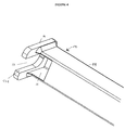
- the connecting element 12 can affect the shape of a tube 15, generally of section square, at least partially open on one of its faces, this tube being closed at one of its ends by a plate 14 comprising the opening 13 substantially in U shape.
- Plate 14 and tube 15 cooperate with each other to allow, during overlapping mounting of the element 12 of connection on the fixing part 3, the overlap by the plate 14 of the body 5 of the attachment part 3 and the overlap by the straight side walls of the tube 15 of the head 4 of the attachment part 3.
- These walls side are shown at 16 in Figure 4.
- the opening of one face of the tube 15 constituting the part 12 connecting over part of its length in the vicinity of the plate 14 carrying the opening 13 makes it possible to spare the equivalent of a room as shown in this figure.
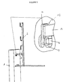
- Attachment piece 3 is housed in the wall, usually after drilling a hole in the wall using a suitable tool. Attachment piece 3 is then introduced into the wall until eventually protrude from building element 1 and is maintained for example by means of a nut 7 screwed onto the body 5 of the attachment part 3. Attachment piece 3 is introduced in element 1 of construction in the state nested grooved roller 9 and head 4 of part 3 of fixing up to a position in which the roller 9 abuts on the face of the construction element 1 intended to receive the safety device 2.
- part 3 is, thanks to its axial sinking limitation member, introduced in element 1 of construction so as to leave a space between head 4 of part 3 and face of construction element 1 intended to receive the security device.
- Flats, where they exist on this fixing part 3 are then installed in a substantially vertical position.
- the fixing part 3 is held in a position fixed, the nut 7 being movable relative to the body 5 of the fixing part 3. This makes it possible to maintain for sure correct orientation of the flats. This orientation of flats can be visually checked by looking at the position of the head 4 of the fixing part 3 when this has a rectangular shape.
- the connecting element 12 is fixed to the device 2 of safety which must be anchored or attached to element 1 of construction.
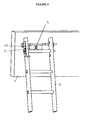
- This safety device 2 can for example be constituted by a scaffolding device of the type intended to simply come to bear on the construction. These scaffolding devices are well known to those versed in this art.
- An example of this device scaffolding is shown in Figure 5.
- the arm affecting the shape of a tube 15 fitted to the element 12 of link is generally fitted to the socket on the scaffolding structure.
- This connecting element 12 can still be permanently installed on the structure scaffolding.
- the plate 14 carrying the opening 13 in U-shaped is arranged at the free end of this arm.
- the scaffolding structure is therefore high to come position above throat 6 or more generally body 5 of the attachment part 3 then lowered to bring the edges 13A opening 13 of the connecting element 12 in taken with groove 6 by an overlapping mounting in enclosing the bottom of the groove 6 with a variable clearance.
- the device security consists of a ladder which includes, at near one of its ends, a cross parallel to two uprights, this cross being equipped of a flap articulated on said crosspiece, this flap having at least one substantially shaped opening 13 of U which is mounted on horseback in a similar manner to that which been described above in the throat 6 of the body 5 or directly on the body 5 of the fixing part 3, the fixing part 3 which may be identical to what has been described above.
- an asset in rotation of the connecting element 12 on the part 3 of fixing is not essential. The goal is simply to prevent the ladder from overturning or sliding support on element 1 of construction.
- the U-shaped opening 13 of the connecting element 12 is generally constituted by a notch formed on an edge of the connecting element 12, in this case a plate 14 of the latter.
Landscapes
- Engineering & Computer Science (AREA)
- Architecture (AREA)
- Mechanical Engineering (AREA)
- Structural Engineering (AREA)
- Civil Engineering (AREA)
- Ladders (AREA)
- Electrical Discharge Machining, Electrochemical Machining, And Combined Machining (AREA)
- Joining Of Building Structures In Genera (AREA)
- Massaging Devices (AREA)
- Steering Control In Accordance With Driving Conditions (AREA)
- Soil Working Implements (AREA)
- Liquid Developers In Electrophotography (AREA)
- Bipolar Transistors (AREA)
- Ropes Or Cables (AREA)
- Transplanting Machines (AREA)
- Emergency Lowering Means (AREA)
Applications Claiming Priority (4)
| Application Number | Priority Date | Filing Date | Title |
|---|---|---|---|
| FR9911951 | 1999-09-24 | ||
| FR9911952A FR2798958B1 (fr) | 1999-09-24 | 1999-09-24 | Dispositif de securite |
| FR9911952 | 1999-09-24 | ||
| FR9911951A FR2799805B1 (fr) | 1999-09-24 | 1999-09-24 | Dispositif d'ancrage dit permanent |
Publications (2)
| Publication Number | Publication Date |
|---|---|
| EP1087075A1 true EP1087075A1 (de) | 2001-03-28 |
| EP1087075B1 EP1087075B1 (de) | 2004-05-26 |
Family
ID=26235115
Family Applications (2)
| Application Number | Title | Priority Date | Filing Date |
|---|---|---|---|
| EP00402634A Expired - Lifetime EP1087075B1 (de) | 1999-09-24 | 2000-09-22 | Permanente Verankerungsvorrichtung |
| EP00402635A Expired - Lifetime EP1087098B1 (de) | 1999-09-24 | 2000-09-22 | Sicherheitsvorrichtung |
Family Applications After (1)
| Application Number | Title | Priority Date | Filing Date |
|---|---|---|---|
| EP00402635A Expired - Lifetime EP1087098B1 (de) | 1999-09-24 | 2000-09-22 | Sicherheitsvorrichtung |
Country Status (6)
| Country | Link |
|---|---|
| EP (2) | EP1087075B1 (de) |
| AT (2) | ATE267932T1 (de) |
| DE (2) | DE60011358T2 (de) |
| DK (2) | DK1087098T3 (de) |
| ES (2) | ES2220361T3 (de) |
| PT (2) | PT1087098E (de) |
Cited By (2)
| Publication number | Priority date | Publication date | Assignee | Title |
|---|---|---|---|---|
| US20160169192A1 (en) * | 2014-12-15 | 2016-06-16 | Acciona Windpower, S.A. | Wind Turbine with a Concrete Tower and Method for the Assembly Thereof |
| CN112227700A (zh) * | 2020-10-13 | 2021-01-15 | 麦田建设有限公司 | 一种建筑工程剪力墙的脚手架临时安装装置 |
Families Citing this family (11)
| Publication number | Priority date | Publication date | Assignee | Title |
|---|---|---|---|---|
| NO20022504L (no) * | 2002-05-28 | 2003-12-01 | Terje H Houen | Sikringsanordning for en stige for å sikre stigen i en skrårettet bruksstilling |
| US7066299B1 (en) | 2004-04-08 | 2006-06-27 | Jeffrey John Fleming | Portable ladder suspension apparatus or a portable ladder for suspension or the combination thereof |
| US7950497B2 (en) | 2004-07-29 | 2011-05-31 | Surrey Hills Hire Pty. Ltd. | Ladder stabilising device |
| GB0523425D0 (en) * | 2005-11-17 | 2005-12-28 | Forest Safety Products Ltd | A ladder safety device |
| CN101469599B (zh) * | 2007-12-28 | 2011-12-07 | 安徽省电力公司蚌埠供电公司 | 绝缘组合梯的组合架立方法 |
| GB0907949D0 (en) * | 2009-05-08 | 2009-06-24 | Arnold Stuart | Fall restraint system and access ladder |
| CN105201400B (zh) * | 2015-09-15 | 2017-03-22 | 国网北京市电力公司 | 固定装置 |
| FR3054592B1 (fr) * | 2016-08-01 | 2020-09-18 | 4Nrj | Dispositif de maintien d'une echelle dans une position d'utilisation pour securiser une intervention en hauteur |
| FR3092131B1 (fr) * | 2019-01-25 | 2022-06-24 | Sade Cie Generale De Travaux Dhydraulique | Dispositif de maintien configuré pour maintenir une échelle contre une surface |
| CN110439244A (zh) * | 2019-08-12 | 2019-11-12 | 中国建筑第二工程局有限公司 | 一种建筑用脚手架 |
| CN112211390A (zh) * | 2020-09-28 | 2021-01-12 | 安徽长青建筑制品有限公司 | 一种建筑施工脚手架用外墙连接结构 |
Citations (3)
| Publication number | Priority date | Publication date | Assignee | Title |
|---|---|---|---|---|
| FR2547632A1 (fr) * | 1983-06-15 | 1984-12-21 | Moreau Pierre | Dispositif d'ancrage |
| FR2610027A1 (fr) * | 1987-01-26 | 1988-07-29 | Ricouard Marcel | Console repliable et reglable en hauteur pour supporter des plates-formes en encorbellement |
| EP0839975A1 (de) * | 1996-10-30 | 1998-05-06 | Dimos, Société Anonyme | Verankerungsvorrichtung |
Family Cites Families (3)
| Publication number | Priority date | Publication date | Assignee | Title |
|---|---|---|---|---|
| FR1292592A (fr) * | 1961-06-17 | 1962-05-04 | Tubesca Anciens Etablissements | Crochet notamment pour échelles ou autres applications et échelles munies du présent crochet ou crochet similaire |
| US4823912A (en) * | 1988-06-06 | 1989-04-25 | Gould William E | Multipurpose ladder fixture |
| DE9013505U1 (de) * | 1990-09-26 | 1992-01-30 | Towet, Manfred |
-
2000
- 2000-09-22 AT AT00402634T patent/ATE267932T1/de not_active IP Right Cessation
- 2000-09-22 EP EP00402634A patent/EP1087075B1/de not_active Expired - Lifetime
- 2000-09-22 DE DE60011358T patent/DE60011358T2/de not_active Expired - Fee Related
- 2000-09-22 AT AT00402635T patent/ATE268861T1/de not_active IP Right Cessation
- 2000-09-22 DE DE60011003T patent/DE60011003T2/de not_active Expired - Fee Related
- 2000-09-22 DK DK00402635T patent/DK1087098T3/da active
- 2000-09-22 DK DK00402634T patent/DK1087075T3/da active
- 2000-09-22 ES ES00402634T patent/ES2220361T3/es not_active Expired - Lifetime
- 2000-09-22 EP EP00402635A patent/EP1087098B1/de not_active Expired - Lifetime
- 2000-09-22 PT PT00402635T patent/PT1087098E/pt unknown
- 2000-09-22 PT PT00402634T patent/PT1087075E/pt unknown
- 2000-09-22 ES ES00402635T patent/ES2220362T3/es not_active Expired - Lifetime
Patent Citations (3)
| Publication number | Priority date | Publication date | Assignee | Title |
|---|---|---|---|---|
| FR2547632A1 (fr) * | 1983-06-15 | 1984-12-21 | Moreau Pierre | Dispositif d'ancrage |
| FR2610027A1 (fr) * | 1987-01-26 | 1988-07-29 | Ricouard Marcel | Console repliable et reglable en hauteur pour supporter des plates-formes en encorbellement |
| EP0839975A1 (de) * | 1996-10-30 | 1998-05-06 | Dimos, Société Anonyme | Verankerungsvorrichtung |
Cited By (3)
| Publication number | Priority date | Publication date | Assignee | Title |
|---|---|---|---|---|
| US20160169192A1 (en) * | 2014-12-15 | 2016-06-16 | Acciona Windpower, S.A. | Wind Turbine with a Concrete Tower and Method for the Assembly Thereof |
| US10100525B2 (en) * | 2014-12-15 | 2018-10-16 | Acciona Windpower, S.A. | Wind turbine with a concrete tower and method for the assembly thereof |
| CN112227700A (zh) * | 2020-10-13 | 2021-01-15 | 麦田建设有限公司 | 一种建筑工程剪力墙的脚手架临时安装装置 |
Also Published As
| Publication number | Publication date |
|---|---|
| PT1087098E (pt) | 2004-10-29 |
| EP1087075B1 (de) | 2004-05-26 |
| DE60011358T2 (de) | 2005-08-25 |
| ATE268861T1 (de) | 2004-06-15 |
| ATE267932T1 (de) | 2004-06-15 |
| PT1087075E (pt) | 2004-09-30 |
| DE60011003D1 (de) | 2004-07-01 |
| EP1087098A1 (de) | 2001-03-28 |
| ES2220361T3 (es) | 2004-12-16 |
| DK1087098T3 (da) | 2004-10-18 |
| DK1087075T3 (da) | 2004-10-04 |
| DE60011003T2 (de) | 2005-08-11 |
| DE60011358D1 (de) | 2004-07-15 |
| EP1087098B1 (de) | 2004-06-09 |
| ES2220362T3 (es) | 2004-12-16 |
Similar Documents
| Publication | Publication Date | Title |
|---|---|---|
| EP1087075B1 (de) | Permanente Verankerungsvorrichtung | |
| CA2202205C (fr) | Dispositif de roulement pour ouvrant coulissant de porte, fenetre ou analogue | |
| EP1957733B1 (de) | Provisorische Verriegelungsvorrichtung | |
| EP2636815B1 (de) | Bügel zum Befestigen eines Handlaufs eines Geländers auf einem Pfosten | |
| FR3035428A3 (fr) | Systeme pour porte de douche, et porte de douche | |
| EP1607568B1 (de) | Halter einer Wickelwelle und entsprechender Vorhang oder Sonnenschutz | |
| FR2893300A1 (fr) | Dispositif d'ecartement securise a l'arrachement | |
| EP0839975A1 (de) | Verankerungsvorrichtung | |
| EP1156172A1 (de) | Elastische Klemme zur Verbindung von Komponenten verschiedener Stabwerke | |
| FR2799805A1 (fr) | Dispositif d'ancrage dit permanent | |
| WO2011077033A2 (fr) | Dispositif d'obturation et ensemble correspondant | |
| EP1087066B1 (de) | Anordnung zur Befestigung eines Einbauelementes in einer Öffnung einer Trägerplatte | |
| EP1775815B1 (de) | Einbaudose mit optimierter Befestigung | |
| EP1775814B1 (de) | Einbaudose mit Spannschraubtriebführung | |
| FR3098538A3 (fr) | Dispositif antivol pour planche de surf | |
| FR2891298A1 (fr) | Arret de volet comportant un blocage reglable | |
| EP3124328B1 (de) | Dachlastenträger | |
| EP0953698B1 (de) | Schelle zur Verbindung eines Armes mit einem Mast | |
| EP3004733A1 (de) | Vorrichtung zur befestigung einer leuchtenarmatur durch mechanisches klemmen ohne notwendigkeit eines werkzeugs | |
| FR3073021B1 (fr) | Ensemble comportant un panneau et un systeme de fixation | |
| FR2472071A1 (fr) | Dispositif de suspension pour portes ou portails | |
| EP3059714B1 (de) | Sperreinsatz für rohrförmigen griff eines einbaufähigen wagens | |
| FR3140393A1 (fr) | Dispositif d’entretoisement réglable en longueur pour la fixation d’une ossature de doublage sur une structure à doubler | |
| EP2719843A1 (de) | Befestigungssystem für Verkleidungspaneele auf einer Gebäudefläche | |
| BE1018281A6 (fr) | Dispositif d'ancrage ameliore pour systeme de securite anti-chute. |
Legal Events
| Date | Code | Title | Description |
|---|---|---|---|
| PUAI | Public reference made under article 153(3) epc to a published international application that has entered the european phase |
Free format text: ORIGINAL CODE: 0009012 |
|
| AK | Designated contracting states |
Kind code of ref document: A1 Designated state(s): AT BE CH CY DE DK ES FI FR GB GR IE IT LI LU MC NL PT SE |
|
| AX | Request for extension of the european patent |
Free format text: AL;LT;LV;MK;RO;SI |
|
| 17P | Request for examination filed |
Effective date: 20010606 |
|
| AKX | Designation fees paid |
Free format text: AT BE CH CY DE DK ES FI FR GB GR IE IT LI LU MC NL PT SE |
|
| GRAP | Despatch of communication of intention to grant a patent |
Free format text: ORIGINAL CODE: EPIDOSNIGR1 |
|
| GRAS | Grant fee paid |
Free format text: ORIGINAL CODE: EPIDOSNIGR3 |
|
| GRAA | (expected) grant |
Free format text: ORIGINAL CODE: 0009210 |
|
| AK | Designated contracting states |
Kind code of ref document: B1 Designated state(s): AT BE CH CY DE DK ES FI FR GB GR IE IT LI LU MC NL PT SE |
|
| PG25 | Lapsed in a contracting state [announced via postgrant information from national office to epo] |
Ref country code: CY Free format text: LAPSE BECAUSE OF FAILURE TO SUBMIT A TRANSLATION OF THE DESCRIPTION OR TO PAY THE FEE WITHIN THE PRESCRIBED TIME-LIMIT Effective date: 20040526 |
|
| REG | Reference to a national code |
Ref country code: GB Ref legal event code: FG4D Free format text: NOT ENGLISH |
|
| REG | Reference to a national code |
Ref country code: CH Ref legal event code: EP |
|
| REG | Reference to a national code |
Ref country code: IE Ref legal event code: FG4D Free format text: FRENCH |
|
| REF | Corresponds to: |
Ref document number: 60011003 Country of ref document: DE Date of ref document: 20040701 Kind code of ref document: P |
|
| REG | Reference to a national code |
Ref country code: CH Ref legal event code: NV Representative=s name: E. BLUM & CO. PATENTANWAELTE |
|
| REG | Reference to a national code |
Ref country code: SE Ref legal event code: TRGR |
|
| PG25 | Lapsed in a contracting state [announced via postgrant information from national office to epo] |
Ref country code: LU Free format text: LAPSE BECAUSE OF NON-PAYMENT OF DUE FEES Effective date: 20040922 |
|
| GBT | Gb: translation of ep patent filed (gb section 77(6)(a)/1977) |
Effective date: 20040908 |
|
| PG25 | Lapsed in a contracting state [announced via postgrant information from national office to epo] |
Ref country code: MC Free format text: LAPSE BECAUSE OF NON-PAYMENT OF DUE FEES Effective date: 20040930 |
|
| REG | Reference to a national code |
Ref country code: PT Ref legal event code: SC4A Free format text: AVAILABILITY OF NATIONAL TRANSLATION Effective date: 20040809 |
|
| REG | Reference to a national code |
Ref country code: DK Ref legal event code: T3 |
|
| REG | Reference to a national code |
Ref country code: GR Ref legal event code: EP Ref document number: 20040402879 Country of ref document: GR |
|
| REG | Reference to a national code |
Ref country code: ES Ref legal event code: FG2A Ref document number: 2220361 Country of ref document: ES Kind code of ref document: T3 |
|
| PLBE | No opposition filed within time limit |
Free format text: ORIGINAL CODE: 0009261 |
|
| STAA | Information on the status of an ep patent application or granted ep patent |
Free format text: STATUS: NO OPPOSITION FILED WITHIN TIME LIMIT |
|
| 26N | No opposition filed |
Effective date: 20050301 |
|
| PGFP | Annual fee paid to national office [announced via postgrant information from national office to epo] |
Ref country code: IE Payment date: 20070727 Year of fee payment: 8 |
|
| PGFP | Annual fee paid to national office [announced via postgrant information from national office to epo] |
Ref country code: DK Payment date: 20070914 Year of fee payment: 8 |
|
| PGFP | Annual fee paid to national office [announced via postgrant information from national office to epo] |
Ref country code: DE Payment date: 20070930 Year of fee payment: 8 |
|
| REG | Reference to a national code |
Ref country code: CH Ref legal event code: PFA Owner name: DIMOS, SOCIETE ANONYME Free format text: DIMOS, SOCIETE ANONYME#RUE DU TERTRE#44150 ANCENIS (FR) -TRANSFER TO- DIMOS, SOCIETE ANONYME#RUE DU TERTRE#44150 ANCENIS (FR) |
|
| PGFP | Annual fee paid to national office [announced via postgrant information from national office to epo] |
Ref country code: AT Payment date: 20070925 Year of fee payment: 8 Ref country code: CH Payment date: 20070806 Year of fee payment: 8 Ref country code: FI Payment date: 20070903 Year of fee payment: 8 |
|
| PGFP | Annual fee paid to national office [announced via postgrant information from national office to epo] |
Ref country code: GB Payment date: 20070806 Year of fee payment: 8 |
|
| PGFP | Annual fee paid to national office [announced via postgrant information from national office to epo] |
Ref country code: NL Payment date: 20070919 Year of fee payment: 8 Ref country code: SE Payment date: 20070917 Year of fee payment: 8 |
|
| PGFP | Annual fee paid to national office [announced via postgrant information from national office to epo] |
Ref country code: GR Payment date: 20070730 Year of fee payment: 8 |
|
| REG | Reference to a national code |
Ref country code: PT Ref legal event code: MM4A Free format text: LAPSE DUE TO NON-PAYMENT OF FEES Effective date: 20090323 |
|
| REG | Reference to a national code |
Ref country code: CH Ref legal event code: PL |
|
| REG | Reference to a national code |
Ref country code: DK Ref legal event code: EBP |
|
| GBPC | Gb: european patent ceased through non-payment of renewal fee |
Effective date: 20080922 |
|
| PG25 | Lapsed in a contracting state [announced via postgrant information from national office to epo] |
Ref country code: FI Free format text: LAPSE BECAUSE OF NON-PAYMENT OF DUE FEES Effective date: 20080922 Ref country code: NL Free format text: LAPSE BECAUSE OF NON-PAYMENT OF DUE FEES Effective date: 20090401 Ref country code: PT Free format text: LAPSE BECAUSE OF NON-PAYMENT OF DUE FEES Effective date: 20090323 |
|
| NLV4 | Nl: lapsed or anulled due to non-payment of the annual fee |
Effective date: 20090401 |
|
| REG | Reference to a national code |
Ref country code: IE Ref legal event code: MM4A |
|
| PG25 | Lapsed in a contracting state [announced via postgrant information from national office to epo] |
Ref country code: IE Free format text: LAPSE BECAUSE OF NON-PAYMENT OF DUE FEES Effective date: 20080922 |
|
| PG25 | Lapsed in a contracting state [announced via postgrant information from national office to epo] |
Ref country code: AT Free format text: LAPSE BECAUSE OF NON-PAYMENT OF DUE FEES Effective date: 20080922 Ref country code: DE Free format text: LAPSE BECAUSE OF NON-PAYMENT OF DUE FEES Effective date: 20090401 |
|
| PG25 | Lapsed in a contracting state [announced via postgrant information from national office to epo] |
Ref country code: CH Free format text: LAPSE BECAUSE OF NON-PAYMENT OF DUE FEES Effective date: 20080930 Ref country code: LI Free format text: LAPSE BECAUSE OF NON-PAYMENT OF DUE FEES Effective date: 20080930 |
|
| PG25 | Lapsed in a contracting state [announced via postgrant information from national office to epo] |
Ref country code: GR Free format text: LAPSE BECAUSE OF NON-PAYMENT OF DUE FEES Effective date: 20090402 Ref country code: GB Free format text: LAPSE BECAUSE OF NON-PAYMENT OF DUE FEES Effective date: 20080922 |
|
| PGFP | Annual fee paid to national office [announced via postgrant information from national office to epo] |
Ref country code: PT Payment date: 20070731 Year of fee payment: 8 |
|
| PG25 | Lapsed in a contracting state [announced via postgrant information from national office to epo] |
Ref country code: DK Free format text: LAPSE BECAUSE OF NON-PAYMENT OF DUE FEES Effective date: 20090331 |
|
| PG25 | Lapsed in a contracting state [announced via postgrant information from national office to epo] |
Ref country code: SE Free format text: LAPSE BECAUSE OF NON-PAYMENT OF DUE FEES Effective date: 20080923 |
|
| PGFP | Annual fee paid to national office [announced via postgrant information from national office to epo] |
Ref country code: IT Payment date: 20100924 Year of fee payment: 11 |
|
| PGFP | Annual fee paid to national office [announced via postgrant information from national office to epo] |
Ref country code: ES Payment date: 20110916 Year of fee payment: 12 |
|
| PG25 | Lapsed in a contracting state [announced via postgrant information from national office to epo] |
Ref country code: IT Free format text: LAPSE BECAUSE OF NON-PAYMENT OF DUE FEES Effective date: 20120922 |
|
| REG | Reference to a national code |
Ref country code: ES Ref legal event code: FD2A Effective date: 20131021 |
|
| PG25 | Lapsed in a contracting state [announced via postgrant information from national office to epo] |
Ref country code: ES Free format text: LAPSE BECAUSE OF NON-PAYMENT OF DUE FEES Effective date: 20120923 |
|
| REG | Reference to a national code |
Ref country code: DE Ref legal event code: R082 Ref document number: 60011003 Country of ref document: DE Representative=s name: FLUEGEL PREISSNER KASTEL SCHOBER, DE Ref country code: DE Ref legal event code: R082 Ref document number: 60011003 Country of ref document: DE Representative=s name: PATENTANWAELTE WAGNER DR. HERRGUTH, DE |
|
| REG | Reference to a national code |
Ref country code: DE Ref legal event code: R082 Ref document number: 60011003 Country of ref document: DE Representative=s name: PATENTANWAELTE WAGNER DR. HERRGUTH, DE |
|
| PGFP | Annual fee paid to national office [announced via postgrant information from national office to epo] |
Ref country code: BE Payment date: 20140919 Year of fee payment: 15 |
|
| REG | Reference to a national code |
Ref country code: FR Ref legal event code: PLFP Year of fee payment: 17 |
|
| PG25 | Lapsed in a contracting state [announced via postgrant information from national office to epo] |
Ref country code: BE Free format text: LAPSE BECAUSE OF NON-PAYMENT OF DUE FEES Effective date: 20150930 |
|
| REG | Reference to a national code |
Ref country code: FR Ref legal event code: PLFP Year of fee payment: 18 |
|
| PGFP | Annual fee paid to national office [announced via postgrant information from national office to epo] |
Ref country code: FR Payment date: 20170928 Year of fee payment: 18 |
|
| PG25 | Lapsed in a contracting state [announced via postgrant information from national office to epo] |
Ref country code: FR Free format text: LAPSE BECAUSE OF NON-PAYMENT OF DUE FEES Effective date: 20180930 |