EP1801023B1 - Storage container with drawers - Google Patents
Storage container with drawers Download PDFInfo
- Publication number
- EP1801023B1 EP1801023B1 EP06301288A EP06301288A EP1801023B1 EP 1801023 B1 EP1801023 B1 EP 1801023B1 EP 06301288 A EP06301288 A EP 06301288A EP 06301288 A EP06301288 A EP 06301288A EP 1801023 B1 EP1801023 B1 EP 1801023B1
- Authority
- EP
- European Patent Office
- Prior art keywords
- support
- rails
- bearing
- base
- guiding
- Prior art date
- Legal status (The legal status is an assumption and is not a legal conclusion. Google has not performed a legal analysis and makes no representation as to the accuracy of the status listed.)
- Not-in-force
Links
- 238000005096 rolling process Methods 0.000 claims description 28
- 238000000605 extraction Methods 0.000 claims description 4
- 230000002093 peripheral effect Effects 0.000 claims description 2
- 239000007787 solid Substances 0.000 claims description 2
- 238000007373 indentation Methods 0.000 claims 2
- 235000004443 Ricinus communis Nutrition 0.000 claims 1
- 240000000528 Ricinus communis Species 0.000 claims 1
- 238000006073 displacement reaction Methods 0.000 description 2
- 238000012423 maintenance Methods 0.000 description 2
- 238000004519 manufacturing process Methods 0.000 description 2
- 230000000712 assembly Effects 0.000 description 1
- 238000000429 assembly Methods 0.000 description 1
- 230000002146 bilateral effect Effects 0.000 description 1
- 230000006835 compression Effects 0.000 description 1
- 238000007906 compression Methods 0.000 description 1
- 238000012986 modification Methods 0.000 description 1
- 230000004048 modification Effects 0.000 description 1
- 238000004806 packaging method and process Methods 0.000 description 1
- 238000009877 rendering Methods 0.000 description 1
- 238000006467 substitution reaction Methods 0.000 description 1
Images


Classifications
-
- B—PERFORMING OPERATIONS; TRANSPORTING
- B65—CONVEYING; PACKING; STORING; HANDLING THIN OR FILAMENTARY MATERIAL
- B65D—CONTAINERS FOR STORAGE OR TRANSPORT OF ARTICLES OR MATERIALS, e.g. BAGS, BARRELS, BOTTLES, BOXES, CANS, CARTONS, CRATES, DRUMS, JARS, TANKS, HOPPERS, FORWARDING CONTAINERS; ACCESSORIES, CLOSURES, OR FITTINGS THEREFOR; PACKAGING ELEMENTS; PACKAGES
- B65D19/00—Pallets or like platforms, with or without side walls, for supporting loads to be lifted or lowered
- B65D19/02—Rigid pallets with side walls, e.g. box pallets
- B65D19/06—Rigid pallets with side walls, e.g. box pallets with bodies formed by uniting or interconnecting two or more components
- B65D19/08—Rigid pallets with side walls, e.g. box pallets with bodies formed by uniting or interconnecting two or more components made wholly or mainly of metal
-
- B—PERFORMING OPERATIONS; TRANSPORTING
- B65—CONVEYING; PACKING; STORING; HANDLING THIN OR FILAMENTARY MATERIAL
- B65D—CONTAINERS FOR STORAGE OR TRANSPORT OF ARTICLES OR MATERIALS, e.g. BAGS, BARRELS, BOTTLES, BOXES, CANS, CARTONS, CRATES, DRUMS, JARS, TANKS, HOPPERS, FORWARDING CONTAINERS; ACCESSORIES, CLOSURES, OR FITTINGS THEREFOR; PACKAGING ELEMENTS; PACKAGES
- B65D19/00—Pallets or like platforms, with or without side walls, for supporting loads to be lifted or lowered
- B65D19/38—Details or accessories
- B65D19/44—Elements or devices for locating articles on platforms
-
- B—PERFORMING OPERATIONS; TRANSPORTING
- B65—CONVEYING; PACKING; STORING; HANDLING THIN OR FILAMENTARY MATERIAL
- B65D—CONTAINERS FOR STORAGE OR TRANSPORT OF ARTICLES OR MATERIALS, e.g. BAGS, BARRELS, BOTTLES, BOXES, CANS, CARTONS, CRATES, DRUMS, JARS, TANKS, HOPPERS, FORWARDING CONTAINERS; ACCESSORIES, CLOSURES, OR FITTINGS THEREFOR; PACKAGING ELEMENTS; PACKAGES
- B65D2519/00—Pallets or like platforms, with or without side walls, for supporting loads to be lifted or lowered
- B65D2519/00004—Details relating to pallets
- B65D2519/00009—Materials
- B65D2519/00014—Materials for the load supporting surface
- B65D2519/00024—Metal
-
- B—PERFORMING OPERATIONS; TRANSPORTING
- B65—CONVEYING; PACKING; STORING; HANDLING THIN OR FILAMENTARY MATERIAL
- B65D—CONTAINERS FOR STORAGE OR TRANSPORT OF ARTICLES OR MATERIALS, e.g. BAGS, BARRELS, BOTTLES, BOXES, CANS, CARTONS, CRATES, DRUMS, JARS, TANKS, HOPPERS, FORWARDING CONTAINERS; ACCESSORIES, CLOSURES, OR FITTINGS THEREFOR; PACKAGING ELEMENTS; PACKAGES
- B65D2519/00—Pallets or like platforms, with or without side walls, for supporting loads to be lifted or lowered
- B65D2519/00004—Details relating to pallets
- B65D2519/00009—Materials
- B65D2519/00049—Materials for the base surface
- B65D2519/00059—Metal
-
- B—PERFORMING OPERATIONS; TRANSPORTING
- B65—CONVEYING; PACKING; STORING; HANDLING THIN OR FILAMENTARY MATERIAL
- B65D—CONTAINERS FOR STORAGE OR TRANSPORT OF ARTICLES OR MATERIALS, e.g. BAGS, BARRELS, BOTTLES, BOXES, CANS, CARTONS, CRATES, DRUMS, JARS, TANKS, HOPPERS, FORWARDING CONTAINERS; ACCESSORIES, CLOSURES, OR FITTINGS THEREFOR; PACKAGING ELEMENTS; PACKAGES
- B65D2519/00—Pallets or like platforms, with or without side walls, for supporting loads to be lifted or lowered
- B65D2519/00004—Details relating to pallets
- B65D2519/00009—Materials
- B65D2519/00154—Materials for the side walls
- B65D2519/00164—Metal
-
- B—PERFORMING OPERATIONS; TRANSPORTING
- B65—CONVEYING; PACKING; STORING; HANDLING THIN OR FILAMENTARY MATERIAL
- B65D—CONTAINERS FOR STORAGE OR TRANSPORT OF ARTICLES OR MATERIALS, e.g. BAGS, BARRELS, BOTTLES, BOXES, CANS, CARTONS, CRATES, DRUMS, JARS, TANKS, HOPPERS, FORWARDING CONTAINERS; ACCESSORIES, CLOSURES, OR FITTINGS THEREFOR; PACKAGING ELEMENTS; PACKAGES
- B65D2519/00—Pallets or like platforms, with or without side walls, for supporting loads to be lifted or lowered
- B65D2519/00004—Details relating to pallets
- B65D2519/00009—Materials
- B65D2519/00223—Materials for the corner elements or corner frames
- B65D2519/00233—Metal
-
- B—PERFORMING OPERATIONS; TRANSPORTING
- B65—CONVEYING; PACKING; STORING; HANDLING THIN OR FILAMENTARY MATERIAL
- B65D—CONTAINERS FOR STORAGE OR TRANSPORT OF ARTICLES OR MATERIALS, e.g. BAGS, BARRELS, BOTTLES, BOXES, CANS, CARTONS, CRATES, DRUMS, JARS, TANKS, HOPPERS, FORWARDING CONTAINERS; ACCESSORIES, CLOSURES, OR FITTINGS THEREFOR; PACKAGING ELEMENTS; PACKAGES
- B65D2519/00—Pallets or like platforms, with or without side walls, for supporting loads to be lifted or lowered
- B65D2519/00004—Details relating to pallets
- B65D2519/00258—Overall construction
- B65D2519/00263—Overall construction of the pallet
- B65D2519/00273—Overall construction of the pallet made of more than one piece
-
- B—PERFORMING OPERATIONS; TRANSPORTING
- B65—CONVEYING; PACKING; STORING; HANDLING THIN OR FILAMENTARY MATERIAL
- B65D—CONTAINERS FOR STORAGE OR TRANSPORT OF ARTICLES OR MATERIALS, e.g. BAGS, BARRELS, BOTTLES, BOXES, CANS, CARTONS, CRATES, DRUMS, JARS, TANKS, HOPPERS, FORWARDING CONTAINERS; ACCESSORIES, CLOSURES, OR FITTINGS THEREFOR; PACKAGING ELEMENTS; PACKAGES
- B65D2519/00—Pallets or like platforms, with or without side walls, for supporting loads to be lifted or lowered
- B65D2519/00004—Details relating to pallets
- B65D2519/00258—Overall construction
- B65D2519/00283—Overall construction of the load supporting surface
- B65D2519/00293—Overall construction of the load supporting surface made of more than one piece
-
- B—PERFORMING OPERATIONS; TRANSPORTING
- B65—CONVEYING; PACKING; STORING; HANDLING THIN OR FILAMENTARY MATERIAL
- B65D—CONTAINERS FOR STORAGE OR TRANSPORT OF ARTICLES OR MATERIALS, e.g. BAGS, BARRELS, BOTTLES, BOXES, CANS, CARTONS, CRATES, DRUMS, JARS, TANKS, HOPPERS, FORWARDING CONTAINERS; ACCESSORIES, CLOSURES, OR FITTINGS THEREFOR; PACKAGING ELEMENTS; PACKAGES
- B65D2519/00—Pallets or like platforms, with or without side walls, for supporting loads to be lifted or lowered
- B65D2519/00004—Details relating to pallets
- B65D2519/00258—Overall construction
- B65D2519/00313—Overall construction of the base surface
- B65D2519/00323—Overall construction of the base surface made of more than one piece
-
- B—PERFORMING OPERATIONS; TRANSPORTING
- B65—CONVEYING; PACKING; STORING; HANDLING THIN OR FILAMENTARY MATERIAL
- B65D—CONTAINERS FOR STORAGE OR TRANSPORT OF ARTICLES OR MATERIALS, e.g. BAGS, BARRELS, BOTTLES, BOXES, CANS, CARTONS, CRATES, DRUMS, JARS, TANKS, HOPPERS, FORWARDING CONTAINERS; ACCESSORIES, CLOSURES, OR FITTINGS THEREFOR; PACKAGING ELEMENTS; PACKAGES
- B65D2519/00—Pallets or like platforms, with or without side walls, for supporting loads to be lifted or lowered
- B65D2519/00004—Details relating to pallets
- B65D2519/00258—Overall construction
- B65D2519/00313—Overall construction of the base surface
- B65D2519/00328—Overall construction of the base surface shape of the contact surface of the base
- B65D2519/00333—Overall construction of the base surface shape of the contact surface of the base contact surface having a stringer-like shape
-
- B—PERFORMING OPERATIONS; TRANSPORTING
- B65—CONVEYING; PACKING; STORING; HANDLING THIN OR FILAMENTARY MATERIAL
- B65D—CONTAINERS FOR STORAGE OR TRANSPORT OF ARTICLES OR MATERIALS, e.g. BAGS, BARRELS, BOTTLES, BOXES, CANS, CARTONS, CRATES, DRUMS, JARS, TANKS, HOPPERS, FORWARDING CONTAINERS; ACCESSORIES, CLOSURES, OR FITTINGS THEREFOR; PACKAGING ELEMENTS; PACKAGES
- B65D2519/00—Pallets or like platforms, with or without side walls, for supporting loads to be lifted or lowered
- B65D2519/00004—Details relating to pallets
- B65D2519/00258—Overall construction
- B65D2519/00313—Overall construction of the base surface
- B65D2519/00328—Overall construction of the base surface shape of the contact surface of the base
- B65D2519/00338—Overall construction of the base surface shape of the contact surface of the base contact surface having a discrete foot-like shape
-
- B—PERFORMING OPERATIONS; TRANSPORTING
- B65—CONVEYING; PACKING; STORING; HANDLING THIN OR FILAMENTARY MATERIAL
- B65D—CONTAINERS FOR STORAGE OR TRANSPORT OF ARTICLES OR MATERIALS, e.g. BAGS, BARRELS, BOTTLES, BOXES, CANS, CARTONS, CRATES, DRUMS, JARS, TANKS, HOPPERS, FORWARDING CONTAINERS; ACCESSORIES, CLOSURES, OR FITTINGS THEREFOR; PACKAGING ELEMENTS; PACKAGES
- B65D2519/00—Pallets or like platforms, with or without side walls, for supporting loads to be lifted or lowered
- B65D2519/00004—Details relating to pallets
- B65D2519/00258—Overall construction
- B65D2519/00492—Overall construction of the side walls
- B65D2519/00502—Overall construction of the side walls whereby at least one side wall is made of two or more pieces
-
- B—PERFORMING OPERATIONS; TRANSPORTING
- B65—CONVEYING; PACKING; STORING; HANDLING THIN OR FILAMENTARY MATERIAL
- B65D—CONTAINERS FOR STORAGE OR TRANSPORT OF ARTICLES OR MATERIALS, e.g. BAGS, BARRELS, BOTTLES, BOXES, CANS, CARTONS, CRATES, DRUMS, JARS, TANKS, HOPPERS, FORWARDING CONTAINERS; ACCESSORIES, CLOSURES, OR FITTINGS THEREFOR; PACKAGING ELEMENTS; PACKAGES
- B65D2519/00—Pallets or like platforms, with or without side walls, for supporting loads to be lifted or lowered
- B65D2519/00004—Details relating to pallets
- B65D2519/00547—Connections
- B65D2519/00577—Connections structures connecting side walls, including corner posts, to each other
- B65D2519/00631—Connections structures connecting side walls, including corner posts, to each other sidewalls not connected to each other, e.g. spaced apart frames
-
- B—PERFORMING OPERATIONS; TRANSPORTING
- B65—CONVEYING; PACKING; STORING; HANDLING THIN OR FILAMENTARY MATERIAL
- B65D—CONTAINERS FOR STORAGE OR TRANSPORT OF ARTICLES OR MATERIALS, e.g. BAGS, BARRELS, BOTTLES, BOXES, CANS, CARTONS, CRATES, DRUMS, JARS, TANKS, HOPPERS, FORWARDING CONTAINERS; ACCESSORIES, CLOSURES, OR FITTINGS THEREFOR; PACKAGING ELEMENTS; PACKAGES
- B65D2519/00—Pallets or like platforms, with or without side walls, for supporting loads to be lifted or lowered
- B65D2519/00004—Details relating to pallets
- B65D2519/00547—Connections
- B65D2519/00636—Connections structures connecting side walls to the pallet
- B65D2519/00666—Structures not intended to be disassembled
-
- B—PERFORMING OPERATIONS; TRANSPORTING
- B65—CONVEYING; PACKING; STORING; HANDLING THIN OR FILAMENTARY MATERIAL
- B65D—CONTAINERS FOR STORAGE OR TRANSPORT OF ARTICLES OR MATERIALS, e.g. BAGS, BARRELS, BOTTLES, BOXES, CANS, CARTONS, CRATES, DRUMS, JARS, TANKS, HOPPERS, FORWARDING CONTAINERS; ACCESSORIES, CLOSURES, OR FITTINGS THEREFOR; PACKAGING ELEMENTS; PACKAGES
- B65D2519/00—Pallets or like platforms, with or without side walls, for supporting loads to be lifted or lowered
- B65D2519/00004—Details relating to pallets
- B65D2519/00547—Connections
- B65D2519/00671—Connections structures connecting corner posts to the pallet
- B65D2519/00701—Structures not intended to be disassembled
-
- B—PERFORMING OPERATIONS; TRANSPORTING
- B65—CONVEYING; PACKING; STORING; HANDLING THIN OR FILAMENTARY MATERIAL
- B65D—CONTAINERS FOR STORAGE OR TRANSPORT OF ARTICLES OR MATERIALS, e.g. BAGS, BARRELS, BOTTLES, BOXES, CANS, CARTONS, CRATES, DRUMS, JARS, TANKS, HOPPERS, FORWARDING CONTAINERS; ACCESSORIES, CLOSURES, OR FITTINGS THEREFOR; PACKAGING ELEMENTS; PACKAGES
- B65D2519/00—Pallets or like platforms, with or without side walls, for supporting loads to be lifted or lowered
- B65D2519/00004—Details relating to pallets
- B65D2519/00736—Details
- B65D2519/0081—Elements or devices for locating articles
- B65D2519/00815—Elements or devices for locating articles on the pallet
-
- B—PERFORMING OPERATIONS; TRANSPORTING
- B65—CONVEYING; PACKING; STORING; HANDLING THIN OR FILAMENTARY MATERIAL
- B65D—CONTAINERS FOR STORAGE OR TRANSPORT OF ARTICLES OR MATERIALS, e.g. BAGS, BARRELS, BOTTLES, BOXES, CANS, CARTONS, CRATES, DRUMS, JARS, TANKS, HOPPERS, FORWARDING CONTAINERS; ACCESSORIES, CLOSURES, OR FITTINGS THEREFOR; PACKAGING ELEMENTS; PACKAGES
- B65D2519/00—Pallets or like platforms, with or without side walls, for supporting loads to be lifted or lowered
- B65D2519/00004—Details relating to pallets
- B65D2519/00736—Details
- B65D2519/0081—Elements or devices for locating articles
- B65D2519/0082—Elements or devices for locating articles in the side wall
-
- B—PERFORMING OPERATIONS; TRANSPORTING
- B65—CONVEYING; PACKING; STORING; HANDLING THIN OR FILAMENTARY MATERIAL
- B65D—CONTAINERS FOR STORAGE OR TRANSPORT OF ARTICLES OR MATERIALS, e.g. BAGS, BARRELS, BOTTLES, BOXES, CANS, CARTONS, CRATES, DRUMS, JARS, TANKS, HOPPERS, FORWARDING CONTAINERS; ACCESSORIES, CLOSURES, OR FITTINGS THEREFOR; PACKAGING ELEMENTS; PACKAGES
- B65D2519/00—Pallets or like platforms, with or without side walls, for supporting loads to be lifted or lowered
- B65D2519/00004—Details relating to pallets
- B65D2519/00736—Details
- B65D2519/00935—Details with special means for nesting or stacking
- B65D2519/00955—Details with special means for nesting or stacking stackable
- B65D2519/00965—Details with special means for nesting or stacking stackable when loaded
- B65D2519/0097—Details with special means for nesting or stacking stackable when loaded through corner posts
-
- B—PERFORMING OPERATIONS; TRANSPORTING
- B65—CONVEYING; PACKING; STORING; HANDLING THIN OR FILAMENTARY MATERIAL
- B65D—CONTAINERS FOR STORAGE OR TRANSPORT OF ARTICLES OR MATERIALS, e.g. BAGS, BARRELS, BOTTLES, BOXES, CANS, CARTONS, CRATES, DRUMS, JARS, TANKS, HOPPERS, FORWARDING CONTAINERS; ACCESSORIES, CLOSURES, OR FITTINGS THEREFOR; PACKAGING ELEMENTS; PACKAGES
- B65D2585/00—Containers, packaging elements or packages specially adapted for particular articles or materials
- B65D2585/68—Containers, packaging elements or packages specially adapted for particular articles or materials for machines, engines, or vehicles in assembled or dismantled form
- B65D2585/6802—Containers, packaging elements or packages specially adapted for particular articles or materials for machines, engines, or vehicles in assembled or dismantled form specific machines, engines or vehicles
- B65D2585/6875—Containers, packaging elements or packages specially adapted for particular articles or materials for machines, engines, or vehicles in assembled or dismantled form specific machines, engines or vehicles engines, motors, machines and vehicle parts
- B65D2585/6882—Containers, packaging elements or packages specially adapted for particular articles or materials for machines, engines, or vehicles in assembled or dismantled form specific machines, engines or vehicles engines, motors, machines and vehicle parts vehicle parts
Definitions
- the present invention relates to the field of storage and packaging, with a view to their transport or their grouped handling, of articles, manufactured products or parts, in particular of components, elements or assemblies useful for the manufacture of machines or vehicles, especially to the chain.
- the invention more particularly relates to a container of the type comprising a base forming a lower frame with generally square or rectangular shape, four uprights or two opposite walls extending from edge areas or corners of said base and at least one, preferably several, loading medium (s) extending substantially parallel to the base.
- Each loading support is in the form of a carrier structure of substantially flat general configuration and is slidably mounted on or in a pair of opposed parallel lateral support and / or guide rails, in the manner of a drawer, each rail being fixed rigidly on a wall or a pair of uprights.
- the loading supports can generally be moved between, on the one hand, a retracted (or retracted) storage position, in which they are located in the outline of the container delimited by the base and the four uprights and, on the other hand , a position at least partially removed or extracted for the establishment or removal of the parts or articles concerned (e) s.
- the document FR 2,711,629 discloses a container according to the preamble of claim 1.
- the present invention is intended in particular to overcome the aforementioned drawbacks.
- the subject of the invention is a container of the aforementioned type, in particular a drawer storage container (s), characterized in that each loading support is slidably guided unilaterally, only one of the two support rails associated with the support concerned also ensuring its guidance in translation.
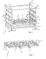
- FIG. 1 , 4 and 5 some of the accompanying drawings show, in part only, a container 1 of the type comprising, on the one hand, a base 1 'forming a lower frame with a generally square or rectangular shape, on the other hand, two opposite side walls or four uprights 2 extending from edge areas or corners of said base 1 'and, finally, at least one, preferably several, support (s) 3 which extend substantially parallel to the base.
- Each loading support 3 is in the form of a carrier structure with a generally planar general configuration and slidably mounted on or in a pair of parallel rails. opposing support and / or lateral guidance 4 and 4 ', in the manner of a drawer, each rail 4, 4' being rigidly attached to a wall or a pair of uprights 2.
- each loading support 3 is slidably guided unilaterally, only one of the two support rails 4 and 4 'associated with the support 3 concerned also ensuring its translation guidance.
- the invention avoids the disadvantages mentioned above in relation to the containers known in the art. Indeed, the maintenance with unguided sliding of the or each support 3 on a 3 'of its two sides 3' and 3 "coming into engagement with the rails or rails 4 and 4 'corresponding corresponding (s), makes it possible to dispense with the need for a precise adjustment between the dimensions of the or each support 3 and the rails 4, 4 'associated therewith, the spacing of said rails 4, 4' and their parallelism. Constructive constraints are thus limited to providing a constant support in all possible positions of the support concerned and a constructive fit between said rails 4, 4 'and the rolling or sliding means of the support 3 concerned.
- each pair of opposed rails 4, 4 ' cooperating for the purpose of supporting and guiding a substantially flat loading support 3 in translation, comprises, on the one hand, a first profiled rail 4 for supporting and guiding, providing a longitudinal rolling or sliding surface in the sliding direction DC simultaneously with a linear guide in the aforesaid direction, and secondly a second profiled rail 4 'of support only, providing a rolling surface or longitudinal sliding in the sliding direction DC without lateral guidance.
- each loading support 3 with a substantially square or rectangular contour according to the outer peripheral contour square or rectangular of the base 1 ', comprises along each of its two opposite lateral sides 3' and 3 ", designed to come into abutment or sliding engagement in the profiled bearing and / or guide rails 4, 4 ', a plurality of rolling means 5 such as rollers, rollers, ball or needle bearings or the like, fixed spaced along the concerned side 3 'or 3 ", the rail 4 of the pair of rails of opposed support 4, 4 'which also ensures the translation guide comprising a raceway 6 groove or groove, preferably with automatic alignment properties or self-centering on a rectilinear trajectory in the direction of sliding DC.
- a plurality of rolling means 5 such as rollers, rollers, ball or needle bearings or the like
- This advantageous embodiment allows the storage of heavy parts and provides optimum comfort of use.
- the support between the rolling means 5 and the rolling surfaces at the level of the rails 4 and 4 ' is preferably of the surface type. However, a linear or quasi-linear support may be tolerated between the rolling means 5 and the rail 4 also guiding, if such support is necessary to obtain the desired sliding properties and without jamming.
- each support and guide rail 4 has opposite rolling faces 6 'inclined toward the bottom of said groove or groove and on which the rolling means 5 bear and run. mounted on the relevant side 3 'of the loading support 3 engaging said support rail 4 and guiding in translation.
- the raceways provided by the two rails 4 and 4 ' are positioned such that the loading supports 3 are arranged substantially parallel to the base 1' and remain parallel to the latter during their movement.
- the rollers, bearings, rollers or the like forming the guided rolling means may optionally have contact faces with the raceway of the corresponding support and guide rail 4, which are inclined in the opposite direction to make a surface contact. between these faces and the rolling faces of said rail 4.
- the rails 4 and 4 ' providing bilateral sliding support for the loading supports 3, consist of C-sections, mounted in pairs, with their longitudinal openings 4 "facing each other and with a profiled wing 7 serving as a bearing surface for the rolling means 5 of the loading support 3 received by said pair of opposite rails 4, 4 'considered ( figures 4 and 5 ).
- one of the rails 4, 4 'of each pair of opposite rails 4, 4' comprises, at its lower flange 7 serving as a bearing surface for the bearing means 5 of the loading support 3 concerned, a longitudinal recess or a V-shaped cross sectional section 8, the upper wings 7 'of the rails 4, 4' which do not serve as bearing surfaces extending to short distance above said rolling means 5.
- pairs of rails 4, 4 'in the form of two C-shaped profiles facing makes it possible to guarantee a conservation of the engagement of the supports 3 in said rails 4, 4' whatever the sliding position of said supports (the rolling means 5 may possibly bear on the upper wings 7 'when the supports 3 are in the extracted position) or whatever the lateral stresses to which these supports are subjected (lateral setting with play).
- each support 3 may comprise, on the one hand, a rectangular frame 9 sized to fit between the two walls or the four uprights 2 in the retracted or retracted position of said support 3 and bearing on two lateral sides of the rolling means 5, on the other hand, one or more site (s) 10 for receiving part (s) or article (s) 11 intended (s) to be stored in the container 1, this (s) site (s) 10 being located (s) inside the aforementioned frame 9 and formed (s) by a solid structure provided with a fingerprint adapted or for a tubular or screened perforated structure, providing, if appropriate, an indexed positioning for this piece (s) or article (s) 11 and, finally, at least one stop means 12 limiting the extraction of said loading support 3 in the extended position, for example intended to come into contact with cooperating means forming a stop or counter stop, present on the extraction side of said support 3.
- each loading support 3 is extractable on two opposite lateral sides of the container 1, the frame 9 of at least one loading support 3 being provided with gripping means 13 for sliding training, such as handles or the like.
- each loading support 3 there may be provided, for each loading support 3, a means 12 "for locking or detachably holding in the retracted or retracted position in which said loading support 3 is entirely arranged in the outline of the container 1, in particular between the four amounts 2.
- Each means 12 may for example consist of a lug biased laterally projecting, for example by the action of a spring.Compression of said spring, and thus a corresponding retraction of the lug, then allow a displacement of the support 3 concerned out of this retracted position centered.
- the container 1 will comprise at least two loading supports 3 extending parallel to the base 1 ', each being associated with a pair of support rails 4 and 4', one of which also ensures the unilateral guidance of the corresponding support 3.
- the base 1 ' may have a tubular constitution adapted to be handled by a handling trolley, preferably pallet-shaped to standard dimensions, and said base 1' may comprise at its level. corners of the lugs 14 adapted to be fitted into the openings of the upper ends of the uprights 2 of another container 1 or in cups 14 'attached to these ends, so as to allow stacking of two containers 1.
- the base 1 ' can be equipped with rolling means, such as for example rollers, rollers or wheels, possibly for some pivoting around an axis. perpendicular to the plane of the base 1 '(not shown).
- rolling means such as for example rollers, rollers or wheels, possibly for some pivoting around an axis. perpendicular to the plane of the base 1 '(not shown).
Abstract
Description
La présente invention concerne le domaine du stockage et du conditionnement, en vue de leur transport ou de leur manipulation groupée, d'articles, de produits manufacturés ou de pièces, notamment de composants, d'éléments ou d'ensembles utiles pour la fabrication de machines ou de véhicules, en particulier à la chaîne.The present invention relates to the field of storage and packaging, with a view to their transport or their grouped handling, of articles, manufactured products or parts, in particular of components, elements or assemblies useful for the manufacture of machines or vehicles, especially to the chain.
L'invention concerne plus particulièrement un conteneur du type comportant une embase formant un châssis inférieur à contour de forme générale carrée ou rectangulaire, quatre montants ou deux parois opposées s'étendant à partir de zones de bords ou des coins de ladite embase et au moins un, préférentiellement plusieurs, support(s) de chargement s'étendant sensiblement parallèlement à l'embase. Chaque support de chargement se présente sous la forme d'une structure porteuse à configuration générale sensiblement plane et est montée avec faculté de coulissement sur ou dans une paire de rails parallèles d'appui et/ou de guidage latéraux opposés, à la manière d'un tiroir, chaque rail étant fixé rigidement sur une paroi ou une paire de montants.The invention more particularly relates to a container of the type comprising a base forming a lower frame with generally square or rectangular shape, four uprights or two opposite walls extending from edge areas or corners of said base and at least one, preferably several, loading medium (s) extending substantially parallel to the base. Each loading support is in the form of a carrier structure of substantially flat general configuration and is slidably mounted on or in a pair of opposed parallel lateral support and / or guide rails, in the manner of a drawer, each rail being fixed rigidly on a wall or a pair of uprights.
Ces conteneurs permettent de stocker, préférentiellement sur plusieurs niveaux, des pièces ou des articles. Les supports de chargement peuvent généralement être déplacés entre, d'une part, une position escamotée (ou rentrée) de stockage, dans laquelle ils sont situés dans le contour du conteneur délimité par l'embase et les quatre montants et, d'autre part, une position au moins partiellement sortie ou extraite pour la mise en place ou l'enlèvement des pièces ou articles concerné(e)s.These containers make it possible to store, preferably on several levels, parts or articles. The loading supports can generally be moved between, on the one hand, a retracted (or retracted) storage position, in which they are located in the outline of the container delimited by the base and the four uprights and, on the other hand , a position at least partially removed or extracted for the establishment or removal of the parts or articles concerned (e) s.
Les conteneurs actuels du type précité (voir par exemple
Le document
En effet, ils nécessitent un ajustement précis des dimensions des supports et des dimensions des rails ou glissières assurant leur maintien et leur guidage en déplacement.Indeed, they require a precise adjustment of the dimensions of the supports and the dimensions of the rails or slides ensuring their maintenance and guidance in displacement.
Cet ajustement dimensionnel oblige les constructeurs de conteneurs à respecter des tolérances de fabrication sévères et à réaliser ensuite des opérations de réglage latéral fastidieuses.This dimensional adjustment forces container manufacturers to adhere to severe manufacturing tolerances and then perform tedious side adjustment operations.
En outre, du fait des déformations induites par les charges supportées durant la durée de vie du conteneur, il est également nécessaire d'effectuer à intervalles réguliers des interventions rectificatives ou de remplacement pour éviter un blocage desdits supports rendant les conteneurs inutilisables.In addition, because of the deformations induced by the loads supported during the lifetime of the container, it is also necessary to carry out at regular intervals corrective or replacement interventions to avoid a blockage of said supports rendering the containers unusable.
La présente invention a notamment pour but de surmonter les inconvénients précités.The present invention is intended in particular to overcome the aforementioned drawbacks.
A cet effet, l'invention a pour objet un conteneur du type précité, en particulier un conteneur de stockage à tiroir(s), caractérisé en ce que chaque support de chargement est guidé en coulissement de manière unilatérale, seul l'un des deux rails d'appui associés au support concerné assurant également son guidage en translation.For this purpose, the subject of the invention is a container of the aforementioned type, in particular a drawer storage container (s), characterized in that each loading support is slidably guided unilaterally, only one of the two support rails associated with the support concerned also ensuring its guidance in translation.
L'invention sera mieux comprise grâce à la description ci-après, qui se rapporte à un mode de réalisation préféré, donné à titre d'exemple non limitatif, et expliqué avec référence aux dessins schématiques annexés, dans lesquels :
- la
figure 1 est une vue en perspective d'un conteneur selon l'invention, apte à recevoir quatre supports de chargement, un seul support étant représenté pour des raisons de visibilité ; - la
figure 2 est une vue en perspective à une échelle différente du support de lafigure 1 ; - la
figure 3 est une vue partielle en perspective à une échelle différente du support desfigures 1 et 2 ; - la
figure 4 est une vue partielle en élévation frontale d'un conteneur similaire à celui de lafigure 1 également muni d'un seul support de chargement, et - la
figure 5 est une vue de détail montrant la coopération par engagement des côtés latéraux opposés du support de lafigure 4 avec les rails opposés solidaires des montants du conteneur.
- the
figure 1 is a perspective view of a container according to the invention, adapted to receive four loading supports, a single support being shown for reasons of visibility; - the
figure 2 is a perspective view on a different scale from the support of thefigure 1 ; - the
figure 3 is a partial perspective view at a different scale from the support ofFigures 1 and 2 ; - the
figure 4 is a partial front elevation view of a container similar to that of thefigure 1 also provided with only one loading support, and - the
figure 5 is a detail view showing the engagement cooperation of the opposite lateral sides of the support of thefigure 4 with the opposite rails secured to the amounts of the container.
Les
Conformément à l'invention, chaque support de chargement 3 est guidé en coulissement de manière unilatérale, seul l'un 4 des deux rails d'appui 4 et 4' associés au support 3 concerné assurant également son guidage en translation.According to the invention, each
En prévoyant un guidage unilatéral du ou des support(s) 3, l'invention permet d'éviter des inconvénients évoqués précédemment en relation avec les conteneurs connus de la technique. En effet, le maintien avec faculté de coulissement non guidé du ou de chaque support 3 sur un 3' de ses deux côtés 3' et 3" venant en engagement avec les rails ou glissières 4 et 4' en regard correspondant(e)s, permet de s'affranchir de la nécessité d'un ajustement précis entre les dimensions du ou de chaque support 3 et des rails 4, 4' qui lui sont associés, de l'écartement desdits rails 4, 4' et de leur parallélisme. Les contraintes constructives se limitent ainsi à la fourniture d'un appui constant dans toutes les positions possibles du support concerné et une adéquation constructive entre lesdits rails 4, 4' et les moyens de roulement ou de glissement du support 3 concerné.By providing a unilateral guide of the support (s) 3, the invention avoids the disadvantages mentioned above in relation to the containers known in the art. Indeed, the maintenance with unguided sliding of the or each
Plus précisément, chaque paire de rails opposés 4, 4', coopérant en vue du support et du guidage en translation d'un support de chargement 3 sensiblement plan, comprend, d'une part, un premier rail profilé 4 d'appui et de guidage, fournissant une surface de roulement ou de glissement longitudinale dans la direction de coulissement DC avec simultanément un guidage linéaire dans la direction précitée, et, d'autre part, un second rail profilé 4' d'appui uniquement, fournissant une surface de roulement ou de glissement longitudinale dans la direction de coulissement DC sans guidage latéral.More specifically, each pair of
Ces rails 4, 4' peuvent être solidarisés directement sur les montants 2 ou être fixés sur des pièces intermédiaires de solidarisation.These
Le coulissement du ou des support(s) dans les rails 4 et 4' peut être réalisé par glissement (prévision de surfaces à faible coefficient de friction).The sliding of the support (s) in the
Néanmoins, en accord avec un mode de réalisation avantageux de l'invention, et comme le montrent les
Ce mode de réalisation avantageux permet le stockage de pièces lourdes et fournit un confort d'utilisation optimal.This advantageous embodiment allows the storage of heavy parts and provides optimum comfort of use.
L'appui entre les moyens de roulement 5 et les surfaces de roulement au niveau des rails 4 et 4' est préférentiellement de type surfacique. Toutefois, un appui linéaire ou quasi linéaire peut être toléré entre les moyens de roulement 5 et le rail 4 assurant également le guidage, si un tel appui est nécessaire pour obtenir les propriétés de coulissement guidé et sans coincement souhaitées.The support between the rolling
Selon une variante de réalisation préférée de l'invention, ressortant en particulier des
Les chemins de roulement fournis par les deux rails 4 et 4' sont positionnés de telle manière que les supports de chargement 3 soient disposés sensiblement parallèlement à l'embase 1' et restent parallèles à cette dernière au cours de leur déplacement.The raceways provided by the two
Les galets, roulements, rouleaux ou analogues formant les moyens de roulement 5 guidés peuvent éventuellement présenter des faces de contact avec le chemin de roulement du rail d'appui et de guidage 4 correspondant, qui sont inclinées dans le sens opposé pour réaliser un contact surfacique entre ces faces et les faces de roulement dudit rail 4.The rollers, bearings, rollers or the like forming the guided rolling means may optionally have contact faces with the raceway of the corresponding support and
Conformément à une caractéristique très avantageuse de l'invention, il peut être prévu que les rails 4 et 4', fournissant un appui bilatéral avec coulissement pour les supports de chargement 3, consistent en des profilés en C, montés par paire, avec leurs ouvertures longitudinales 4" mutuellement en regard et avec une aile profilée 7 servant de surface d'appui pour les moyens de roulement 5 du support de chargement 3 reçu par ladite paire de rails opposés 4, 4' considérée (
De plus, l'un 4 des rails 4, 4' de chaque paire de rails 4, 4' opposés, formant rail d'appui et de guidage, comporte, au niveau de son aile inférieure 7 servant de surface d'appui pour les moyens de roulement 5 du support de chargement 3 concerné, une empreinte longitudinale ou un profilé rapporté à section en forme de V 8, les ailes supérieures 7' des rails 4, 4' qui ne servent pas de surfaces d'appui s'étendant à faible distance au-dessus desdits moyens de roulement 5.In addition, one of the
Une telle réalisation des paires de rails 4, 4' sous la forme de deux profilés en C en regard permet de garantir une conservation de l'engagement des supports 3 dans lesdits rails 4, 4' quelle que soit la position en coulissement desdits supports (les moyens de roulement 5 peuvent éventuellement prendre appui sur les ailes supérieures 7' lorsque les supports 3 sont en position extraite) ou quelles que soient les sollicitations latérales auxquelles ces supports sont soumis (calage latéral avec jeu).Such an embodiment of the pairs of
En accord avec une réalisation pratique simple et économique de l'invention, chaque support 3 peut comprendre, d'une part, un cadre rectangulaire 9 dimensionné pour s'inscrire entre les deux parois ou les quatre montants 2 en position escamotée ou rentrée dudit support 3 et portant sur deux côtés latéraux des moyens de roulement 5, d'autre part, un ou plusieurs site(s) 10 de réception de pièce(s) ou d'article(s) 11 destiné(e)(s) à être stocké(e)(s) dans le conteneur 1, ce(s) site(s) 10 étant situé(s) à l'intérieur du cadre 9 précité et formé(s) par une structure pleine pourvue d'une empreinte adaptée ou pour une structure ajourée tubulaire ou grillagée, en fournissant le cas échéant un positionnement indexé pour cet(te)(s) pièce(s) ou article(s) 11 et, enfin, au moins un moyen formant butée 12 limitant l'extraction dudit support de chargement 3 en position sortie, par exemple destiné à venir en contact sur un moyen 12' coopérant formant arrêt ou contre-butée, présent du côté de l'extraction dudit support 3.In accordance with a simple and economical practical embodiment of the invention, each
Préférentiellement, chaque support de chargement 3 est extractible sur deux côtés latéraux opposés du conteneur 1, le cadre 9 d'au moins un support de chargement 3 étant pourvu de moyens de préhension 13 en vue de son entraînement en coulissement, tels que des poignées ou analogues.Preferably, each
De plus, il peut être prévu, pour chaque support de chargement 3, un moyen 12" de verrouillage ou de maintien amovible en position escamotée ou rentrée dans laquelle ledit support de chargement 3 est entièrement disposé dans le contour du conteneur 1, en particulier entre les quatre montants 2.In addition, there may be provided, for each
Chaque moyen 12" peut par exemple consister en un ergot sollicité latéralement en saillie, par exemple par l'action d'un ressort. Une compression dudit ressort, et donc un escamotage correspondant de l'ergot, autorisera alors un déplacement du support 3 concerné hors de cette position escamotée centrée.Each
Comme il est possible de le déduire de la
Afin de fournir un conteneur léger et aisément superposable, l'embase 1' peut présenter une constitution tubulaire apte à être manipulée par un chariot de manutention, préférentiellement en forme de palette aux dimensions standard, et ladite embase 1' peut comporter au niveau de ses coins des ergots 14 aptes à être emboîtés dans les ouvertures des extrémités supérieures des montants 2 d'un autre conteneur 1 ou dans des coupelles 14' rapportées sur ces extrémités, de manière à autoriser un gerbage de deux conteneurs 1.In order to provide a lightweight and easily stackable container, the base 1 'may have a tubular constitution adapted to be handled by a handling trolley, preferably pallet-shaped to standard dimensions, and said base 1' may comprise at its level. corners of the
En variante ou de manière supplémentaire, l'embase 1' peut être équipée de moyens de roulement, tels que par exemple des galets, des rouleaux ou des roues, éventuellement pour certain(e)s pivotant(e)s autour d'un axe perpendiculaire au plan de l'embase 1' (non représenté).Alternatively or additionally, the base 1 'can be equipped with rolling means, such as for example rollers, rollers or wheels, possibly for some pivoting around an axis. perpendicular to the plane of the base 1 '(not shown).
Bien entendu, l'invention n'est pas limitée au mode de réalisation décrit et représenté aux dessins annexés. Des modifications restent possibles, notamment du point de vue de la constitution des divers éléments ou par substitution d'équivalents techniques, sans sortir pour autant du domaine de protection de l'invention.Of course, the invention is not limited to the embodiment described and shown in the accompanying drawings. Modifications are possible, particularly from the point of view of the constitution of the various elements or by substitution of technical equivalents, without departing from the scope of protection of the invention.
Claims (11)
- Container (1) of the type comprising, on the one hand, a base (1') forming a lower frame with a generally square or rectangular contour, on the other hand, two opposite side walls or four posts (2) extending from the edge areas or the corners of said base (1'), and lastly, at least one, preferably several, load supports (3) extending substantially parallel to the base, each load support (3) being in the form of a support structure with a virtually plane configuration and mounted with the ability to slide on or in a pair of opposite parallel bearing rails and/or lateral guide rails (4 and 4') in the manner of a drawer, each rail (4, 4') being fixed rigidly onto a wall or a pair of posts (2), the container (1) being characterised in that each load support (3) is guided in a sliding manner in a unilateral manner, only one (4) of the two bearing rails (4 and 4') connected to the support (3) concerned ensuring its guiding in translation.
- Container according to claim 1, characterised in that each pair of opposite rails (4, 4'), which cooperate for supporting and guiding in translation a load support (3) that is substantially planar, comprises, on the one hand, a first profiled bearing and guiding rail (4) providing a longitudinal rolling or sliding surface in the sliding direction (DC) with simultaneously linear guiding in the said direction and, on the other hand, a second profiled rail (4') for bearing only, providing a longitudinal rolling or sliding surface in the sliding direction (DC) without lateral guiding.
- Container according to claim 1 or 2, characterised in that each load support (3) with a square or rectangular contour according to the virtually square or rectangular exterior peripheral contour of the base (1'), comprises along the length of each of its two lateral opposite sides (3' and 3"), designed to bear or enter into sliding engagement with the profiled bearing and/or guiding rails (4, 4'), a plurality of rolling means (5) such as rollers, wheels, ball bearings or needle roller bearings or the like, fixed spaced apart along the relevant side (3' or 3"), the rail (4) of the pair of opposite bearing rails (4, 4') which also ensures guiding in translation comprising a grooved or fluted rolling path (6), preferably with automatic alignment properties or autocentring properties on a rectilinear trajectory in the direction of sliding (DS).
- Container according to claim 3, characterised in that the grooved or fluted rolling path (6) of each bearing and guiding rail (4) comprises opposite rolling faces (6') inclined towards the base of the said groove or fluting and on which the rolling means (5), which are mounted on the relevant side (3') of the load support (3) engaging said rail (4) for bearing and guiding in translation, bear and circulate.
- Container according to any one of claims 3 and 4, characterised in that the rails (4 and 4'), providing a sliding bearing for the load supports (3), consist of C-profiles, mounted in pairs with their longitudinal openings (4") mutually opposite one another and with a profiled blade (7) used as a bearing surface for the rolling means (5) of the load support (3) received by said relevant pair of opposite rails (4, 4').
- Container according to claim 5, characterised in that one (4) of the rails (4, 4') of each pair of opposite rails (4, 4'), forming a bearing and guiding rail, comprises at the level of its lower blade (7) used as a bearing surface for the rolling means (5) of the relevant load support (3) a longitudinal indentation or profile with a V-shape cross section (8), the upper blades (7') of the rails (4, 4') which do not use bearing surfaces extend a short distance above said rolling means (5).
- Container according to any one of claims 1 to 6, characterised in that each load support (3) comprises, on the one hand, a rectangular (9) frame dimensioned to be fitted between the two walls or four posts (2) in a retracted or returned position of said support (3) and bearing on two lateral sides of the rolling means (5), on the other hand, one or more sites (10) for receiving part(s) or article(s) (11) intended to be stored in the container (1), said site(s) (10) being located on the inside of the said frame (9) and formed by a solid structure provided with an adapted indentation or a tubular or meshed lattice structure, supplying if necessary an index positioning for said part(s) or article(s) (11), and lastly at least one stop forming means (12) limiting the extraction of said load support (3) in an output position, for example designed to come into contact with a cooperating means (12') forming a stop or counter stop on the extraction side of said support (3).
- Container according to claim 7, characterised in that each load support (3) is extractable on two opposite lateral sides of the container (1), in that the frame (9) of at least one load support (3) is provided with gripping means (13) for driving in a sliding manner, such as handles or the like, and in that for each load support (3) there is a locking means (12") or securing means for holding in a retracted or returned position in which said load support (3) is arranged completely within the contour of the container (1), in particular between the two lateral walls or four posts (2).
- Container according to any one of claims 1 to 8, characterised in that it comprises at least two load supports (3) which extend parallel to the base (1'), each one associated with a pair of support rails (4 and 4'), one of which (4) also ensures the unilateral guiding of the corresponding support (3).
- Container according to any one of claims 1 to 9, characterised in that the base (1') has a tubular form able to be manipulated by a handling carriage, preferably in the form of a pallet of standard dimensions, and in that said base (1') has pins (14) in the corners which are suitable for slotting into the openings of the top ends of the tubular posts (2) of another container (1) or into cups (14') attached to the ends, in such a way as to allow the stacking of the two containers (1) in question.
- Container according to any one of claims 1 to 10, characterised in that the base (1') is equipped with rolling means such as for example rollers, castors or wheels, some pivoting around an axle perpendicular to the plane of the base (1').
Applications Claiming Priority (1)
| Application Number | Priority Date | Filing Date | Title |
|---|---|---|---|
| FR0513293A FR2895380B1 (en) | 2005-12-23 | 2005-12-23 | DRAWER STORAGE CONTAINER |
Publications (2)
| Publication Number | Publication Date |
|---|---|
| EP1801023A1 EP1801023A1 (en) | 2007-06-27 |
| EP1801023B1 true EP1801023B1 (en) | 2011-01-26 |
Family
ID=37110383
Family Applications (1)
| Application Number | Title | Priority Date | Filing Date |
|---|---|---|---|
| EP06301288A Not-in-force EP1801023B1 (en) | 2005-12-23 | 2006-12-22 | Storage container with drawers |
Country Status (4)
| Country | Link |
|---|---|
| EP (1) | EP1801023B1 (en) |
| AT (1) | ATE496836T1 (en) |
| DE (1) | DE602006019819D1 (en) |
| FR (1) | FR2895380B1 (en) |
Families Citing this family (3)
| Publication number | Priority date | Publication date | Assignee | Title |
|---|---|---|---|---|
| DE102007032336A1 (en) * | 2007-07-11 | 2009-01-22 | Gebhardt Transport- Und Lagersysteme Gmbh | transport system |
| CN105857847A (en) * | 2016-05-26 | 2016-08-17 | 苏州万盛塑胶科技股份有限公司 | Material barrel for feeding machine |
| DE202016103925U1 (en) * | 2016-07-20 | 2017-10-23 | Sth-Systeme Gmbh | Pet crate |
Family Cites Families (8)
| Publication number | Priority date | Publication date | Assignee | Title |
|---|---|---|---|---|
| US1176508A (en) * | 1914-02-26 | 1916-03-21 | Martin A Williams | Hat-display rack. |
| US4685571A (en) * | 1986-11-03 | 1987-08-11 | Chrysler Motors Corporation | Shipping unit |
| FR2711629B1 (en) * | 1993-10-22 | 1996-03-08 | Sipa Roller | Drawer magazine for storing heavy loads. |
| DE4336043A1 (en) * | 1993-10-22 | 1995-04-27 | Braun Pebra Gmbh | Supporting frame for storing and transporting bumpers and similar components |
| FR2761920A1 (en) * | 1997-04-09 | 1998-10-16 | Jean Francois Bulteau | Storage stand for storage of long objects, e.g. bars, tubes etc |
| FR2842789B1 (en) * | 2002-07-26 | 2004-10-15 | Europ De Conception De Contene | LOCKER CONTAINER FOR STORING OBJECTS |
| DE10354182B4 (en) * | 2003-11-19 | 2011-10-06 | Kr-Porsiplast Verpackungssysteme Gmbh | suspension |
| US7690515B2 (en) * | 2004-02-23 | 2010-04-06 | Tim Albert Thibodeau | Container/cargo rack with integrated lock down and indexing slide |
-
2005
- 2005-12-23 FR FR0513293A patent/FR2895380B1/en not_active Expired - Fee Related
-
2006
- 2006-12-22 DE DE602006019819T patent/DE602006019819D1/en active Active
- 2006-12-22 AT AT06301288T patent/ATE496836T1/en not_active IP Right Cessation
- 2006-12-22 EP EP06301288A patent/EP1801023B1/en not_active Not-in-force
Also Published As
| Publication number | Publication date |
|---|---|
| ATE496836T1 (en) | 2011-02-15 |
| DE602006019819D1 (en) | 2011-03-10 |
| FR2895380B1 (en) | 2008-03-14 |
| EP1801023A1 (en) | 2007-06-27 |
| FR2895380A1 (en) | 2007-06-29 |
Similar Documents
| Publication | Publication Date | Title |
|---|---|---|
| EP1801023B1 (en) | Storage container with drawers | |
| FR2906983A1 (en) | Overhead storage device for use with e.g. kitchen furniture, has vertical displacement device to displace storage case between raised and lowered positions, and sliding device enabling case to horizontally slide with respect to support | |
| EP3296154B1 (en) | Loading device with sliding platform | |
| FR2557861A1 (en) | ARRANGEMENT OF ROLLS FOR FORMING A ROLL TABLE FOR THE TRANSPORT IN PARTICULAR OF WORKPIECES FOR FLAT SHAPE | |
| WO2014198721A1 (en) | Improved support device for a motor vehicle boot panel | |
| EP1270048A1 (en) | Rack with skis in an inclined position | |
| FR2711629A1 (en) | Magazine with drawers for storing heavy loads | |
| EP3013639B2 (en) | Facility for loading and unloading containers | |
| CH640797A5 (en) | Storage installation comprising carriages which can be moved in two directions | |
| FR2699897A1 (en) | Storage and unloading unit for articles in boxes, pallets or packages | |
| FR3059984A1 (en) | DEVICE FOR ADJUSTING PACKAGE | |
| EP0036817A1 (en) | Interior fittings for a vehicle such as a folding caravan | |
| FR2946943A1 (en) | Carriage for transporting body piece i.e. bumper skins, of vehicle i.e. truck, has posts surrounded by volume, so that change of direction of cover is carried at level of walls of posts that is turned toward outside of carriage | |
| FR2661656A1 (en) | Pallet box | |
| FR3064258A1 (en) | ASSEMBLY FOR GUIDING A LOADING TROLLEY | |
| BE1009110A4 (en) | Carriage charge. | |
| EP2570359A1 (en) | Pallet for handling and storage of goods | |
| FR2934133A1 (en) | Table e.g. kitchen table, has retracting unit including displacement system displacing main plates with respect to extension plate, and translation system that vertically displaces main plates to certain height or descends main plates | |
| FR2977854A1 (en) | Body for e.g. refrigerated goods transporting road vehicle, has notches and end stop cooperating with beams to obtain longitudinal retaining of beams with respect to storage rails, where storage and loading rails are placed one above other | |
| FR2969101A1 (en) | Assembly of chairs and trolley for storage and transport of chairs, has lower longitudinal units and upper longitudinal units, and stops provided for locking position of chairs in rear end region of trolley | |
| FR2908399A1 (en) | Object e.g. plate, storing tower, has carriage including mobile portion horizontally and slidably connected with respect to fixed portion, where mobile portion has lifting unit lifting assembly of objects provided inside storage zones | |
| FR2906794A1 (en) | Metallic seat frame supporting and transporting device for e.g. transport container, has side rails forming support unit at ground or displaced on roller races, where side rails rest on rollers by U-shaped base surrounded by wings | |
| EP0116528A2 (en) | Pallet with platform | |
| EP0588275B1 (en) | Storing device having movable support elements | |
| FR3010981A1 (en) | ENHANCEMENT INTENDED TO BE INSTALLED ON THE GROUND TO SUPPORT A PACKAGING CONTAINER OF PARTS |
Legal Events
| Date | Code | Title | Description |
|---|---|---|---|
| PUAI | Public reference made under article 153(3) epc to a published international application that has entered the european phase |
Free format text: ORIGINAL CODE: 0009012 |
|
| AK | Designated contracting states |
Kind code of ref document: A1 Designated state(s): AT BE BG CH CY CZ DE DK EE ES FI FR GB GR HU IE IS IT LI LT LU LV MC NL PL PT RO SE SI SK TR |
|
| AX | Request for extension of the european patent |
Extension state: AL BA HR MK YU |
|
| 17P | Request for examination filed |
Effective date: 20071221 |
|
| AKX | Designation fees paid |
Designated state(s): AT BE BG CH CY CZ DE DK EE ES FI FR GB GR HU IE IS IT LI LT LU LV MC NL PL PT RO SE SI SK TR |
|
| 17Q | First examination report despatched |
Effective date: 20080222 |
|
| GRAP | Despatch of communication of intention to grant a patent |
Free format text: ORIGINAL CODE: EPIDOSNIGR1 |
|
| GRAS | Grant fee paid |
Free format text: ORIGINAL CODE: EPIDOSNIGR3 |
|
| GRAA | (expected) grant |
Free format text: ORIGINAL CODE: 0009210 |
|
| AK | Designated contracting states |
Kind code of ref document: B1 Designated state(s): AT BE BG CH CY CZ DE DK EE ES FI FR GB GR HU IE IS IT LI LT LU LV MC NL PL PT RO SE SI SK TR |
|
| REG | Reference to a national code |
Ref country code: GB Ref legal event code: FG4D Free format text: NOT ENGLISH |
|
| REG | Reference to a national code |
Ref country code: CH Ref legal event code: EP |
|
| REG | Reference to a national code |
Ref country code: IE Ref legal event code: FG4D Free format text: LANGUAGE OF EP DOCUMENT: FRENCH |
|
| REF | Corresponds to: |
Ref document number: 602006019819 Country of ref document: DE Date of ref document: 20110310 Kind code of ref document: P |
|
| REG | Reference to a national code |
Ref country code: DE Ref legal event code: R096 Ref document number: 602006019819 Country of ref document: DE Effective date: 20110310 |
|
| REG | Reference to a national code |
Ref country code: NL Ref legal event code: VDEP Effective date: 20110126 |
|
| LTIE | Lt: invalidation of european patent or patent extension |
Effective date: 20110126 |
|
| PG25 | Lapsed in a contracting state [announced via postgrant information from national office to epo] |
Ref country code: LV Free format text: LAPSE BECAUSE OF FAILURE TO SUBMIT A TRANSLATION OF THE DESCRIPTION OR TO PAY THE FEE WITHIN THE PRESCRIBED TIME-LIMIT Effective date: 20110126 Ref country code: PT Free format text: LAPSE BECAUSE OF FAILURE TO SUBMIT A TRANSLATION OF THE DESCRIPTION OR TO PAY THE FEE WITHIN THE PRESCRIBED TIME-LIMIT Effective date: 20110526 Ref country code: IS Free format text: LAPSE BECAUSE OF FAILURE TO SUBMIT A TRANSLATION OF THE DESCRIPTION OR TO PAY THE FEE WITHIN THE PRESCRIBED TIME-LIMIT Effective date: 20110526 Ref country code: ES Free format text: LAPSE BECAUSE OF FAILURE TO SUBMIT A TRANSLATION OF THE DESCRIPTION OR TO PAY THE FEE WITHIN THE PRESCRIBED TIME-LIMIT Effective date: 20110507 Ref country code: SE Free format text: LAPSE BECAUSE OF FAILURE TO SUBMIT A TRANSLATION OF THE DESCRIPTION OR TO PAY THE FEE WITHIN THE PRESCRIBED TIME-LIMIT Effective date: 20110126 Ref country code: GR Free format text: LAPSE BECAUSE OF FAILURE TO SUBMIT A TRANSLATION OF THE DESCRIPTION OR TO PAY THE FEE WITHIN THE PRESCRIBED TIME-LIMIT Effective date: 20110427 Ref country code: LT Free format text: LAPSE BECAUSE OF FAILURE TO SUBMIT A TRANSLATION OF THE DESCRIPTION OR TO PAY THE FEE WITHIN THE PRESCRIBED TIME-LIMIT Effective date: 20110126 |
|
| REG | Reference to a national code |
Ref country code: IE Ref legal event code: FD4D |
|
| PG25 | Lapsed in a contracting state [announced via postgrant information from national office to epo] |
Ref country code: CY Free format text: LAPSE BECAUSE OF FAILURE TO SUBMIT A TRANSLATION OF THE DESCRIPTION OR TO PAY THE FEE WITHIN THE PRESCRIBED TIME-LIMIT Effective date: 20110126 Ref country code: SI Free format text: LAPSE BECAUSE OF FAILURE TO SUBMIT A TRANSLATION OF THE DESCRIPTION OR TO PAY THE FEE WITHIN THE PRESCRIBED TIME-LIMIT Effective date: 20110126 Ref country code: BG Free format text: LAPSE BECAUSE OF FAILURE TO SUBMIT A TRANSLATION OF THE DESCRIPTION OR TO PAY THE FEE WITHIN THE PRESCRIBED TIME-LIMIT Effective date: 20110426 Ref country code: AT Free format text: LAPSE BECAUSE OF FAILURE TO SUBMIT A TRANSLATION OF THE DESCRIPTION OR TO PAY THE FEE WITHIN THE PRESCRIBED TIME-LIMIT Effective date: 20110126 Ref country code: PL Free format text: LAPSE BECAUSE OF FAILURE TO SUBMIT A TRANSLATION OF THE DESCRIPTION OR TO PAY THE FEE WITHIN THE PRESCRIBED TIME-LIMIT Effective date: 20110126 Ref country code: NL Free format text: LAPSE BECAUSE OF FAILURE TO SUBMIT A TRANSLATION OF THE DESCRIPTION OR TO PAY THE FEE WITHIN THE PRESCRIBED TIME-LIMIT Effective date: 20110126 Ref country code: FI Free format text: LAPSE BECAUSE OF FAILURE TO SUBMIT A TRANSLATION OF THE DESCRIPTION OR TO PAY THE FEE WITHIN THE PRESCRIBED TIME-LIMIT Effective date: 20110126 |
|
| PG25 | Lapsed in a contracting state [announced via postgrant information from national office to epo] |
Ref country code: EE Free format text: LAPSE BECAUSE OF FAILURE TO SUBMIT A TRANSLATION OF THE DESCRIPTION OR TO PAY THE FEE WITHIN THE PRESCRIBED TIME-LIMIT Effective date: 20110126 Ref country code: DK Free format text: LAPSE BECAUSE OF FAILURE TO SUBMIT A TRANSLATION OF THE DESCRIPTION OR TO PAY THE FEE WITHIN THE PRESCRIBED TIME-LIMIT Effective date: 20110126 Ref country code: IE Free format text: LAPSE BECAUSE OF FAILURE TO SUBMIT A TRANSLATION OF THE DESCRIPTION OR TO PAY THE FEE WITHIN THE PRESCRIBED TIME-LIMIT Effective date: 20110126 |
|
| PG25 | Lapsed in a contracting state [announced via postgrant information from national office to epo] |
Ref country code: CZ Free format text: LAPSE BECAUSE OF FAILURE TO SUBMIT A TRANSLATION OF THE DESCRIPTION OR TO PAY THE FEE WITHIN THE PRESCRIBED TIME-LIMIT Effective date: 20110126 Ref country code: RO Free format text: LAPSE BECAUSE OF FAILURE TO SUBMIT A TRANSLATION OF THE DESCRIPTION OR TO PAY THE FEE WITHIN THE PRESCRIBED TIME-LIMIT Effective date: 20110126 Ref country code: SK Free format text: LAPSE BECAUSE OF FAILURE TO SUBMIT A TRANSLATION OF THE DESCRIPTION OR TO PAY THE FEE WITHIN THE PRESCRIBED TIME-LIMIT Effective date: 20110126 |
|
| PLBE | No opposition filed within time limit |
Free format text: ORIGINAL CODE: 0009261 |
|
| STAA | Information on the status of an ep patent application or granted ep patent |
Free format text: STATUS: NO OPPOSITION FILED WITHIN TIME LIMIT |
|
| 26N | No opposition filed |
Effective date: 20111027 |
|
| REG | Reference to a national code |
Ref country code: DE Ref legal event code: R097 Ref document number: 602006019819 Country of ref document: DE Effective date: 20111027 |
|
| PG25 | Lapsed in a contracting state [announced via postgrant information from national office to epo] |
Ref country code: IT Free format text: LAPSE BECAUSE OF FAILURE TO SUBMIT A TRANSLATION OF THE DESCRIPTION OR TO PAY THE FEE WITHIN THE PRESCRIBED TIME-LIMIT Effective date: 20110126 |
|
| BERE | Be: lapsed |
Owner name: INDUSTRIE DE THERMOFORMAGE ET MECANO SOUDURE (SOC Effective date: 20111231 |
|
| PG25 | Lapsed in a contracting state [announced via postgrant information from national office to epo] |
Ref country code: MC Free format text: LAPSE BECAUSE OF NON-PAYMENT OF DUE FEES Effective date: 20111231 |
|
| REG | Reference to a national code |
Ref country code: CH Ref legal event code: PL |
|
| GBPC | Gb: european patent ceased through non-payment of renewal fee |
Effective date: 20111222 |
|
| REG | Reference to a national code |
Ref country code: DE Ref legal event code: R119 Ref document number: 602006019819 Country of ref document: DE Effective date: 20120703 |
|
| PG25 | Lapsed in a contracting state [announced via postgrant information from national office to epo] |
Ref country code: BE Free format text: LAPSE BECAUSE OF NON-PAYMENT OF DUE FEES Effective date: 20111231 Ref country code: DE Free format text: LAPSE BECAUSE OF NON-PAYMENT OF DUE FEES Effective date: 20120703 Ref country code: GB Free format text: LAPSE BECAUSE OF NON-PAYMENT OF DUE FEES Effective date: 20111222 Ref country code: CH Free format text: LAPSE BECAUSE OF NON-PAYMENT OF DUE FEES Effective date: 20111231 Ref country code: LI Free format text: LAPSE BECAUSE OF NON-PAYMENT OF DUE FEES Effective date: 20111231 |
|
| PG25 | Lapsed in a contracting state [announced via postgrant information from national office to epo] |
Ref country code: LU Free format text: LAPSE BECAUSE OF NON-PAYMENT OF DUE FEES Effective date: 20111222 |
|
| PG25 | Lapsed in a contracting state [announced via postgrant information from national office to epo] |
Ref country code: TR Free format text: LAPSE BECAUSE OF FAILURE TO SUBMIT A TRANSLATION OF THE DESCRIPTION OR TO PAY THE FEE WITHIN THE PRESCRIBED TIME-LIMIT Effective date: 20110126 |
|
| PG25 | Lapsed in a contracting state [announced via postgrant information from national office to epo] |
Ref country code: HU Free format text: LAPSE BECAUSE OF FAILURE TO SUBMIT A TRANSLATION OF THE DESCRIPTION OR TO PAY THE FEE WITHIN THE PRESCRIBED TIME-LIMIT Effective date: 20110126 |
|
| REG | Reference to a national code |
Ref country code: FR Ref legal event code: PLFP Year of fee payment: 10 |
|
| REG | Reference to a national code |
Ref country code: FR Ref legal event code: PLFP Year of fee payment: 11 |
|
| REG | Reference to a national code |
Ref country code: FR Ref legal event code: PLFP Year of fee payment: 12 |
|
| PGFP | Annual fee paid to national office [announced via postgrant information from national office to epo] |
Ref country code: FR Payment date: 20211224 Year of fee payment: 16 |
|
| PG25 | Lapsed in a contracting state [announced via postgrant information from national office to epo] |
Ref country code: FR Free format text: LAPSE BECAUSE OF NON-PAYMENT OF DUE FEES Effective date: 20221231 |