EP0116528A2 - Pallet with platform - Google Patents
Pallet with platform Download PDFInfo
- Publication number
- EP0116528A2 EP0116528A2 EP84870012A EP84870012A EP0116528A2 EP 0116528 A2 EP0116528 A2 EP 0116528A2 EP 84870012 A EP84870012 A EP 84870012A EP 84870012 A EP84870012 A EP 84870012A EP 0116528 A2 EP0116528 A2 EP 0116528A2
- Authority
- EP
- European Patent Office
- Prior art keywords
- housing
- sole
- pallet according
- floor
- pallet
- Prior art date
- Legal status (The legal status is an assumption and is not a legal conclusion. Google has not performed a legal analysis and makes no representation as to the accuracy of the status listed.)
- Withdrawn
Links
Images


Classifications
-
- B—PERFORMING OPERATIONS; TRANSPORTING
- B65—CONVEYING; PACKING; STORING; HANDLING THIN OR FILAMENTARY MATERIAL
- B65D—CONTAINERS FOR STORAGE OR TRANSPORT OF ARTICLES OR MATERIALS, e.g. BAGS, BARRELS, BOTTLES, BOXES, CANS, CARTONS, CRATES, DRUMS, JARS, TANKS, HOPPERS, FORWARDING CONTAINERS; ACCESSORIES, CLOSURES, OR FITTINGS THEREFOR; PACKAGING ELEMENTS; PACKAGES
- B65D19/00—Pallets or like platforms, with or without side walls, for supporting loads to be lifted or lowered
- B65D19/0004—Rigid pallets without side walls
- B65D19/0053—Rigid pallets without side walls the load supporting surface being made of more than one element
- B65D19/0077—Rigid pallets without side walls the load supporting surface being made of more than one element forming discontinuous or non-planar contact surfaces
- B65D19/0089—Rigid pallets without side walls the load supporting surface being made of more than one element forming discontinuous or non-planar contact surfaces the base surface being made of more than one element
- B65D19/0091—Rigid pallets without side walls the load supporting surface being made of more than one element forming discontinuous or non-planar contact surfaces the base surface being made of more than one element forming a continuous plane contact surface
-
- B—PERFORMING OPERATIONS; TRANSPORTING
- B65—CONVEYING; PACKING; STORING; HANDLING THIN OR FILAMENTARY MATERIAL
- B65D—CONTAINERS FOR STORAGE OR TRANSPORT OF ARTICLES OR MATERIALS, e.g. BAGS, BARRELS, BOTTLES, BOXES, CANS, CARTONS, CRATES, DRUMS, JARS, TANKS, HOPPERS, FORWARDING CONTAINERS; ACCESSORIES, CLOSURES, OR FITTINGS THEREFOR; PACKAGING ELEMENTS; PACKAGES
- B65D2519/00—Pallets or like platforms, with or without side walls, for supporting loads to be lifted or lowered
- B65D2519/00004—Details relating to pallets
- B65D2519/00009—Materials
- B65D2519/00014—Materials for the load supporting surface
- B65D2519/00029—Wood
-
- B—PERFORMING OPERATIONS; TRANSPORTING
- B65—CONVEYING; PACKING; STORING; HANDLING THIN OR FILAMENTARY MATERIAL
- B65D—CONTAINERS FOR STORAGE OR TRANSPORT OF ARTICLES OR MATERIALS, e.g. BAGS, BARRELS, BOTTLES, BOXES, CANS, CARTONS, CRATES, DRUMS, JARS, TANKS, HOPPERS, FORWARDING CONTAINERS; ACCESSORIES, CLOSURES, OR FITTINGS THEREFOR; PACKAGING ELEMENTS; PACKAGES
- B65D2519/00—Pallets or like platforms, with or without side walls, for supporting loads to be lifted or lowered
- B65D2519/00004—Details relating to pallets
- B65D2519/00009—Materials
- B65D2519/00049—Materials for the base surface
- B65D2519/00064—Wood
-
- B—PERFORMING OPERATIONS; TRANSPORTING
- B65—CONVEYING; PACKING; STORING; HANDLING THIN OR FILAMENTARY MATERIAL
- B65D—CONTAINERS FOR STORAGE OR TRANSPORT OF ARTICLES OR MATERIALS, e.g. BAGS, BARRELS, BOTTLES, BOXES, CANS, CARTONS, CRATES, DRUMS, JARS, TANKS, HOPPERS, FORWARDING CONTAINERS; ACCESSORIES, CLOSURES, OR FITTINGS THEREFOR; PACKAGING ELEMENTS; PACKAGES
- B65D2519/00—Pallets or like platforms, with or without side walls, for supporting loads to be lifted or lowered
- B65D2519/00004—Details relating to pallets
- B65D2519/00009—Materials
- B65D2519/00084—Materials for the non-integral separating spacer
- B65D2519/00099—Wood
-
- B—PERFORMING OPERATIONS; TRANSPORTING
- B65—CONVEYING; PACKING; STORING; HANDLING THIN OR FILAMENTARY MATERIAL
- B65D—CONTAINERS FOR STORAGE OR TRANSPORT OF ARTICLES OR MATERIALS, e.g. BAGS, BARRELS, BOTTLES, BOXES, CANS, CARTONS, CRATES, DRUMS, JARS, TANKS, HOPPERS, FORWARDING CONTAINERS; ACCESSORIES, CLOSURES, OR FITTINGS THEREFOR; PACKAGING ELEMENTS; PACKAGES
- B65D2519/00—Pallets or like platforms, with or without side walls, for supporting loads to be lifted or lowered
- B65D2519/00004—Details relating to pallets
- B65D2519/00009—Materials
- B65D2519/00084—Materials for the non-integral separating spacer
- B65D2519/00104—Plastic
-
- B—PERFORMING OPERATIONS; TRANSPORTING
- B65—CONVEYING; PACKING; STORING; HANDLING THIN OR FILAMENTARY MATERIAL
- B65D—CONTAINERS FOR STORAGE OR TRANSPORT OF ARTICLES OR MATERIALS, e.g. BAGS, BARRELS, BOTTLES, BOXES, CANS, CARTONS, CRATES, DRUMS, JARS, TANKS, HOPPERS, FORWARDING CONTAINERS; ACCESSORIES, CLOSURES, OR FITTINGS THEREFOR; PACKAGING ELEMENTS; PACKAGES
- B65D2519/00—Pallets or like platforms, with or without side walls, for supporting loads to be lifted or lowered
- B65D2519/00004—Details relating to pallets
- B65D2519/00258—Overall construction
- B65D2519/00283—Overall construction of the load supporting surface
- B65D2519/00293—Overall construction of the load supporting surface made of more than one piece
-
- B—PERFORMING OPERATIONS; TRANSPORTING
- B65—CONVEYING; PACKING; STORING; HANDLING THIN OR FILAMENTARY MATERIAL
- B65D—CONTAINERS FOR STORAGE OR TRANSPORT OF ARTICLES OR MATERIALS, e.g. BAGS, BARRELS, BOTTLES, BOXES, CANS, CARTONS, CRATES, DRUMS, JARS, TANKS, HOPPERS, FORWARDING CONTAINERS; ACCESSORIES, CLOSURES, OR FITTINGS THEREFOR; PACKAGING ELEMENTS; PACKAGES
- B65D2519/00—Pallets or like platforms, with or without side walls, for supporting loads to be lifted or lowered
- B65D2519/00004—Details relating to pallets
- B65D2519/00258—Overall construction
- B65D2519/00283—Overall construction of the load supporting surface
- B65D2519/00298—Overall construction of the load supporting surface skeleton type
-
- B—PERFORMING OPERATIONS; TRANSPORTING
- B65—CONVEYING; PACKING; STORING; HANDLING THIN OR FILAMENTARY MATERIAL
- B65D—CONTAINERS FOR STORAGE OR TRANSPORT OF ARTICLES OR MATERIALS, e.g. BAGS, BARRELS, BOTTLES, BOXES, CANS, CARTONS, CRATES, DRUMS, JARS, TANKS, HOPPERS, FORWARDING CONTAINERS; ACCESSORIES, CLOSURES, OR FITTINGS THEREFOR; PACKAGING ELEMENTS; PACKAGES
- B65D2519/00—Pallets or like platforms, with or without side walls, for supporting loads to be lifted or lowered
- B65D2519/00004—Details relating to pallets
- B65D2519/00258—Overall construction
- B65D2519/00313—Overall construction of the base surface
- B65D2519/00323—Overall construction of the base surface made of more than one piece
-
- B—PERFORMING OPERATIONS; TRANSPORTING
- B65—CONVEYING; PACKING; STORING; HANDLING THIN OR FILAMENTARY MATERIAL
- B65D—CONTAINERS FOR STORAGE OR TRANSPORT OF ARTICLES OR MATERIALS, e.g. BAGS, BARRELS, BOTTLES, BOXES, CANS, CARTONS, CRATES, DRUMS, JARS, TANKS, HOPPERS, FORWARDING CONTAINERS; ACCESSORIES, CLOSURES, OR FITTINGS THEREFOR; PACKAGING ELEMENTS; PACKAGES
- B65D2519/00—Pallets or like platforms, with or without side walls, for supporting loads to be lifted or lowered
- B65D2519/00004—Details relating to pallets
- B65D2519/00258—Overall construction
- B65D2519/00313—Overall construction of the base surface
- B65D2519/00328—Overall construction of the base surface shape of the contact surface of the base
- B65D2519/00333—Overall construction of the base surface shape of the contact surface of the base contact surface having a stringer-like shape
-
- B—PERFORMING OPERATIONS; TRANSPORTING
- B65—CONVEYING; PACKING; STORING; HANDLING THIN OR FILAMENTARY MATERIAL
- B65D—CONTAINERS FOR STORAGE OR TRANSPORT OF ARTICLES OR MATERIALS, e.g. BAGS, BARRELS, BOTTLES, BOXES, CANS, CARTONS, CRATES, DRUMS, JARS, TANKS, HOPPERS, FORWARDING CONTAINERS; ACCESSORIES, CLOSURES, OR FITTINGS THEREFOR; PACKAGING ELEMENTS; PACKAGES
- B65D2519/00—Pallets or like platforms, with or without side walls, for supporting loads to be lifted or lowered
- B65D2519/00004—Details relating to pallets
- B65D2519/00258—Overall construction
- B65D2519/00368—Overall construction of the non-integral separating spacer
- B65D2519/00373—Overall construction of the non-integral separating spacer whereby at least one spacer is made of one piece
-
- B—PERFORMING OPERATIONS; TRANSPORTING
- B65—CONVEYING; PACKING; STORING; HANDLING THIN OR FILAMENTARY MATERIAL
- B65D—CONTAINERS FOR STORAGE OR TRANSPORT OF ARTICLES OR MATERIALS, e.g. BAGS, BARRELS, BOTTLES, BOXES, CANS, CARTONS, CRATES, DRUMS, JARS, TANKS, HOPPERS, FORWARDING CONTAINERS; ACCESSORIES, CLOSURES, OR FITTINGS THEREFOR; PACKAGING ELEMENTS; PACKAGES
- B65D2519/00—Pallets or like platforms, with or without side walls, for supporting loads to be lifted or lowered
- B65D2519/00004—Details relating to pallets
- B65D2519/00258—Overall construction
- B65D2519/00398—Overall construction reinforcements
- B65D2519/00432—Non-integral, e.g. inserts
-
- B—PERFORMING OPERATIONS; TRANSPORTING
- B65—CONVEYING; PACKING; STORING; HANDLING THIN OR FILAMENTARY MATERIAL
- B65D—CONTAINERS FOR STORAGE OR TRANSPORT OF ARTICLES OR MATERIALS, e.g. BAGS, BARRELS, BOTTLES, BOXES, CANS, CARTONS, CRATES, DRUMS, JARS, TANKS, HOPPERS, FORWARDING CONTAINERS; ACCESSORIES, CLOSURES, OR FITTINGS THEREFOR; PACKAGING ELEMENTS; PACKAGES
- B65D2519/00—Pallets or like platforms, with or without side walls, for supporting loads to be lifted or lowered
- B65D2519/00004—Details relating to pallets
- B65D2519/00547—Connections
- B65D2519/00552—Structures connecting the constitutive elements of the pallet to each other, i.e. load supporting surface, base surface and/or separate spacer
- B65D2519/00557—Structures connecting the constitutive elements of the pallet to each other, i.e. load supporting surface, base surface and/or separate spacer without separate auxiliary elements
- B65D2519/00562—Structures connecting the constitutive elements of the pallet to each other, i.e. load supporting surface, base surface and/or separate spacer without separate auxiliary elements chemical connection, e.g. glued, welded, sealed
-
- B—PERFORMING OPERATIONS; TRANSPORTING
- B65—CONVEYING; PACKING; STORING; HANDLING THIN OR FILAMENTARY MATERIAL
- B65D—CONTAINERS FOR STORAGE OR TRANSPORT OF ARTICLES OR MATERIALS, e.g. BAGS, BARRELS, BOTTLES, BOXES, CANS, CARTONS, CRATES, DRUMS, JARS, TANKS, HOPPERS, FORWARDING CONTAINERS; ACCESSORIES, CLOSURES, OR FITTINGS THEREFOR; PACKAGING ELEMENTS; PACKAGES
- B65D2519/00—Pallets or like platforms, with or without side walls, for supporting loads to be lifted or lowered
- B65D2519/00004—Details relating to pallets
- B65D2519/00547—Connections
- B65D2519/00552—Structures connecting the constitutive elements of the pallet to each other, i.e. load supporting surface, base surface and/or separate spacer
- B65D2519/00572—Structures connecting the constitutive elements of the pallet to each other, i.e. load supporting surface, base surface and/or separate spacer with separate auxiliary element, e.g. screws, nails, bayonets
Definitions
- the invention relates to a floor and sole pallet with spacing insert, for forklift.
- the object of the invention is to provide a moderate price, with ease, a pallet of the kind described, capable of supporting high loads.
- Such a pallet can have the dimension 1000 x 1200 x 168 mm.
- This pallet is essentially characterized by reinforcing elements such as metal or synthetic rods, the ends of which, bent or arranged at right angles, are received in the spacers and the right part of which is in direct contact with the sole. , the floor or the crosspiece.
- Another embodiment consists in that the sole, the floor or the cross member comprises in its contact face with the reinforcement element at least one housing for a corresponding part of this reinforcement element.
- a groove made in the top or bottom face of the sole, of the floor or of the cross member receives the wing or wings of a T or U-shaped reinforcement profile for example.
- the reinforcing element is thus anchored in the wood and prevented from deforming under the weight of the loads placed on the pallet. He can no longer interfere the passage of lifting or other tools.
- the pallet has a floor 1 and a bottom sole 2 separated from each other by spacers 3.
- the floor 1 and the sole 2 each consist of several wooden planks.
- Each spacer 3 comprises a body advantageously made of synthetic material reinforced with glass fibers, formed by molding.
- a tubular housing 4 receives in the axis of the spacer 3 a crimping tube 4a which passes through its free ends on the one hand the floor and on the other hand the sole and joins them.
- Another housing 5 receives an end 6 bent at right angles to a tube 7 extending from a spacer 3 to the neighboring spacer 3 and directly supporting the floorboards 1.
- the tubes 7 of floor reinforcement extend transversely to the planks.
- Each spacer 3 includes such a housing 5 on either side of the housing 4.
- Another housing 8 on either side of the central tube 4 receives the end 9 bent at right angles to a tube 10 s 'extending from a spacer 3 to the neighboring spacer but this time in direct contact with the boards of the sole 2 and perpendicular to the aforementioned tubes 7.
- the tubes 7 and 10 can be made of metal or of reinforced synthetic material.
- the synthetic material which can be used for the spacers 3 and for the tubes 7 and 10 can be chosen from polyesters, polypropylene and high density polyethylene.
- the assembly of the floor 1 and the sole 2 is done by crimping by means of the crimping tubes 4a. Between the spacers 3, the boards are connected to the tubes 7 by twisted or corrugated nails 11 or by similar means.
- the reinforcing tube 7 is for example of rectangular cross section and the shape of each housing 5 is adapted to that of the end 6 so that the free end of this end bears directly on the sole 2.
- the reinforcement tube 10 is for example also of rectangular cross section and the shape of each housing 8 is adapted to that of the end 9 of this tube 10 so that its free end bears directly on the floor 1.
- the part of the tube 10 which extends between the spacers 3 is crushed or flattened.
- the spacer 3 is thus reinforced by the crimping tube 4a, at least one end 6 of a tube 7 and at least one end 9 of a tube 10.
- the openings for the longitudinal and transverse engagement of the elevator forks are delimited between the spacers 3, the floor 1 and the sole 2.
- the spacing of the tube 10 facilitates the engagement of the forks transverse to the boards. from the floor.
- the housings 5 are arranged in the immediate vicinity of the housing 4 and, therefore, the housings 8 to be out of reach of the housings 5 are located at a greater distance from the housing 4. It it is however also possible to arrange the housings 5 and 8 at the same distance from the axis of the spacer 3 as shown in FIG. 6.
- the folded end 6 at right angles can stop halfway between the housing 5 in which case this housing can receive another end 6 bent at right angles to a reinforcing element 7 lower disposed in contact with the sole 2.
- the solidity of the assembly is increased and it is also possible to conceive of a similar arrangement at the level of the reinforcing elements 10.
- the sole 2 has two grooves 21 parallel and longitudinal.
- the reinforcing element 10 takes, by its straight part, bearing on the sole 2. It has in cross section the shape of a U whose two wings 12 are received in the grooves 21.
- the part of the sole between the two grooves can be hollowed out slightly, taking into account the thickness of the profile, so that the outer surface of the latter comes flush with the sole. 2.
- the reinforcement element of the sole or of the floor or of the crosspieces can be made of plastic material, for example filled polyester, of the kind shaped by "pulltrusion" (British company called Pultrex).
- It can have a T-shaped cross section or a U, for example.
- the horizontal part of the reinforcing element is placed in contact with the sole or the floor or the cross member and other parts of the reinforcing element, vertical, bear on the sole or under the floor or cross member and are held by the spacers.
- the protruding part or wing of the T is received in a corresponding groove made in the bottom or top face of the sole, the floor or the cross-member (FIG. 11).
- the wings of this element are received in corresponding grooves made in the bottom or top face of the sole, the floor or the cross-member.
- plastic reinforcing profiles can be made in such a way that they wrap around the boards which form the soles, floors and crosspieces (Figure 12). This wrapping can be completed by anchoring the side edges in the wood (Figure 13).
- the assembly of the pallet is advantageously done by gluing.
- the spacers can be cylindrical or parallelepiped.
- a screw, a lag screw or a steel rod provided with a head can be used, the other end of which is crushed.
- FIG. 14 shows an embodiment of a piece with a reduced space requirement, suitable for a light pallet.
- the spacer of parallelepiped shape has for example the following dimensions: height 100 mm, width 100 mm, depth 20 mm. It comprises a central housing 14 passing through and coaxial extending from one horizontal end face 20 to the other and intended to receive an end 6 or 9 bent at right angles to a reinforcing element 7 or 10 and, on either side of the housing 14 a crimping tube 15.
- the central housing 14 is of rectangular cross section and measures for example 30 mm by 15 mm while each crimping tube is round and has, for example, a diameter of 15 mm.
- the crimping tubes 15 protrude from the end faces 20 by about 10 mm in order to be received in corresponding perforations made in the floor respectively in the base of the pallet. The crimping of the tubes 15 in the pallet can be done hot.
- spacer 3 shown in FIG. 15 makes it possible to assemble boards at an end-to-end angle without having to reduce their thickness in order to be able to intersect them.
- the spacer comprises a first preferably rounded part 30 intended to bear on one of the boards. It is extended by a second preferably rounded part 31 intended to bear on the adjoining transverse board, each of these parts comprises a housing respectively 32, 33 for a crimping tube as well as one or more housings respectively 34, 35, 36 for vertical reinforcing elements.
Abstract
Description
L'invention concerne une palette à plancher et semelle avec intercalation de pièces d'écartement, pour élévateur à fourche.The invention relates to a floor and sole pallet with spacing insert, for forklift.
Le but de l'invention est de procurer à prix modéré, avec facilité, une palette du genre décrit, capable de supporter des charges élevées.The object of the invention is to provide a moderate price, with ease, a pallet of the kind described, capable of supporting high loads.
Elle s'applique en particulier aux palettes à quatre entrées comportant trois pièces de distance par côté et une pièce de distance centrale. Une telle palette peut avoir comme dimension 1000 x 1200 x 168 mm.It applies in particular to pallets with four entrances comprising three distance pieces per side and a central distance piece. Such a pallet can have the dimension 1000 x 1200 x 168 mm.
Cette palette se caractérise essentiellement par des éléments de renforcement tels que tiges en métal ou matière synthétique, dont les extrémités, pliées ou disposées à angle droit, sont reçues dans les pièces d'écartement et dont la partie droite est en contact direct avec la semelle, le plancher ou la traverse.This pallet is essentially characterized by reinforcing elements such as metal or synthetic rods, the ends of which, bent or arranged at right angles, are received in the spacers and the right part of which is in direct contact with the sole. , the floor or the crosspiece.
Une autre forme d'exécution consiste en ce que la semelle, le plancher ou la traverse comporte dans sa face de contact avec l'élément de renforcement au moins un logement pour une partie correspondante de cet élément de renforcement. Une rainure pratiquée dans la face de dessus ou de dessous de la semelle, du plancher ou de la traverse reçoit la ou les ailes d'un profilé de renforcement en T ou en U par exemple.Another embodiment consists in that the sole, the floor or the cross member comprises in its contact face with the reinforcement element at least one housing for a corresponding part of this reinforcement element. A groove made in the top or bottom face of the sole, of the floor or of the cross member receives the wing or wings of a T or U-shaped reinforcement profile for example.
L'élément de renforcement se trouve ainsi ancré dans le bois et empêché de se déformer sous le poids des charges posées sur la palette. Il ne peut plus gêner le passage des outils de levage ou autres.The reinforcing element is thus anchored in the wood and prevented from deforming under the weight of the loads placed on the pallet. He can no longer interfere the passage of lifting or other tools.
D'autres particularités de l'invention ressortiront de la description suivante qui fait référence aux dessins ci-annexés dans lesquels :
- La figure 1 représente une palette selon l'invention, en perspective.
- Les figures 2 et 3 représentent la même palette en coupe respectivement longitudinale et transversale.
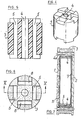
- La figure 4 représente en perspective une première forme de réalisation de la pièce de distance ou d'écartement.
- Les figures 5 et 6 représentent l'une en coupe, l'autre en plan de dessus, une variante de cette pièce d'écartement.
- La figure 7 représente une variante de réalisation du renforcement de la palette.
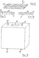
- La figure 8 est une vue en perspective d'une semelle aménagée.
- Les figures 9 à 13 représentent en coupe des réalisations de semelles munies d'un renforcement.
- Les figures 14 et 15 représentent, l'une en perspective, l'autre en plan de dessus, deux variantes de pièces d'écartement.
- Figure 1 shows a pallet according to the invention, in perspective.
- Figures 2 and 3 show the same pallet in longitudinal and transverse sections, respectively.
- Figure 4 shows in perspective a first embodiment of the distance piece or spacer.
- Figures 5 and 6 show one in section, the other in top plan, a variant of this spacer.
- Figure 7 shows an alternative embodiment of the reinforcement of the pallet.
- Figure 8 is a perspective view of a fitted sole.
- Figures 9 to 13 show in section the realizations of soles provided with a reinforcement.
- Figures 14 and 15 show, one in perspective, the other in top plan, two variants of spacers.
La palette comporte un plancher 1 et une semelle inférieure 2 séparés l'un de l'autre par des pièces d'écartement 3.The pallet has a
Le plancher 1 et la semelle 2 se composent chacun de plusieurs planches de bois.The
Chaque pièce d'écartement 3 comporte un corps avantageusement en matière synthétique renforcée par des fibres de verre, formé par moulage. Un logement tubulaire 4 reçoit dans l'axe de la pièce d'écartement 3 un tube de sertissage 4a lequel traverse par ses extrémités libres d'une part le plancher et d'autre part la semelle et les réunit. Un autre logement 5 reçoit une extrémité 6 pliée à angle droit d'un tube 7 s'étendant d'une pièce d'écartement 3 à la pièce d'écartement 3 voisine et soutenant directement les planches du plancher 1. Avantageusement les tubes 7 de renforcement du plancher s'étendent transversalement aux planches. Chaque pièce d'écartement 3 comporte un tel logement 5 de part et d'autre du logement 4. Un autre logement 8 de part et d'autre du tube central 4 reçoit l'extrémité 9 pliée à angle droit d'un tube 10 s'étendant d'une pièce d'écartement 3 à la pièce d'écartement voisine mais cette fois-ci en contact direct avec les planche de la semelle 2 et perpendiculairement aux tubes 7 précités. Les tubes 7 et 10 peuvent être en métal ou en matière synthétique renforcée.Each
La matière synthétique utilisable pour les pièces d'écartement 3 et pour les tubes 7 et 10 peut être choisie parmi les polyesters, le polypropylène et le polyéthylène haute densité.The synthetic material which can be used for the
Aux endroits des pièces d'écartement 3, l'assemblage du plancher 1 et de la semelle 2 se fait par sertissage au moyen des tubes de sertissage 4a. Entre les pièces d'écartement 3, les planches sont reliées aux tubes 7 par des clous torsadés ou annelés 11 ou par des moyens analogues.At the locations of the
Le tube de renforcement 7 est par exemple de section transversale rectangulaire et la forme de chaque logement 5 est adaptée à celle de l'extrémité 6 de façon telle que le bout libre de cette extrémité prenne directement appui sur la semelle 2.The reinforcing
Le tube de renforcement 10 est par exemple également de section transversale rectangulaire et la forme de chaque logement 8 est adaptée à celle de l'extrémité 9 de ce tube 10 de façon telle que son bout libre prenne directement appui sur le plancher 1.The
De préférence la partie du tube 10 qui s'étend entre les pièces d'écartement 3 est écrasée ou aplatie.Preferably the part of the
La pièce d'écartement 3 se trouve ainsi renforcée par le tube de sertissage 4a, au moins une extrémité 6 d'un tube 7 et au moins une extrémité 9 d'un tube 10.The
Les ouvertures pour l'engagement longitudinal et transversal des fourches d'élévateur sont délimitées entre les pièces d'écartement 3, le plancher 1 et la semelle 2. L'écartement du tube 10 facilite l'engagement des fourches dans le sens transversal aux planches du plancher.The openings for the longitudinal and transverse engagement of the elevator forks are delimited between the
Dans la forme de réalisation représentée sur la figure 4, les logements 5 sont disposés au voisinage immédiat du logement 4 et, de ce fait, les logements 8 pour être hors de portée des logements 5 se trouvent à plus grande distance du logement 4. Il est cependant également possible de disposer les logements 5 et 8 à la même distance de l'axe de la pièce d'écartement 3 comme représenté sur la figure 6.In the embodiment shown in Figure 4, the
Comme représenté sur la figure 7, l'extrémité 6 pliée à angle droit peut s'arrêter à mi-chemin du logement 5 auquel cas ce logement peut recevoir une autre extrémité 6 pliée à angle droit d'un élément de renforcement 7 inférieur disposé au contact de la semelle 2. La solidité de l'ensemble se trouve augmentée et on peut d'ailleurs concevoir une disposition similaire au niveau des éléments de renforcement 10.As shown in Figure 7, the folded
Dans la forme de réalisation représentée sur la figure' 8, la semelle 2 comporte deux rainures 21 parallèles et longitudinales. L'élément de renforcement 10 prend, par sa partie droite, appui sur la semelle 2. Il a en section transversale la forme d'un U dont les deux ailes 12 sont reçues dans les rainures 21.In the embodiment shown in Figure '8, the
En variante, comme représenté sur la figure 9, la partie de la semelle comprise entre les deux rainures peut être évidée légèrement en tenant compte de l'épaisseur du profilé, de façon que la surface extérieure de celui-ci vienne à ras de la semelle 2.Alternatively, as shown in Figure 9, the part of the sole between the two grooves can be hollowed out slightly, taking into account the thickness of the profile, so that the outer surface of the latter comes flush with the sole. 2.
La description qui précède s'applique également aux planchers et aux traverses. On peut donc prévoir des éléments de renforcement 7 identiques aux éléments 10 et dans le plancher supérieur l ou les traverses, des rainures appropriées à la réception des ailes des profilés de renforcement.The above description also applies to floors and sleepers. It is therefore possible to provide reinforcing
L'élément de renforcement de la semelle ou du plancher ou des traverses, au lieu d'être en métal peut être réalisé en matière plastique, par exemple en polyester chargé, du genre façonné par "pulltrusion" (société britannique dite Pultrex).The reinforcement element of the sole or of the floor or of the crosspieces, instead of being made of metal, can be made of plastic material, for example filled polyester, of the kind shaped by "pulltrusion" (British company called Pultrex).
Il peut avoir en section transversale la forme d'un T ou d'un U, par exemple.It can have a T-shaped cross section or a U, for example.
Dans ce cas, la partie horizontale de l'élément de renforcement se place au contact de la semelle ou du plancher ou de la traverse et d'autres parties de l'élément de renforcement, verticales, prennent appui sur la semelle ou sous le plancher ou la traverse et sont maintenues par les pièces d'écartement.In this case, the horizontal part of the reinforcing element is placed in contact with the sole or the floor or the cross member and other parts of the reinforcing element, vertical, bear on the sole or under the floor or cross member and are held by the spacers.
En cas d'élément de renforcement profilé en T, la partie saillante ou aile du T est reçue dans une rainure correspondante pratiquée dans la face de dessous ou de dessus de la semelle, du plancher ou de la traverse (figure 11).In the case of a T-shaped reinforcing element, the protruding part or wing of the T is received in a corresponding groove made in the bottom or top face of the sole, the floor or the cross-member (FIG. 11).
En cas d'élément de renforcement en U, les ailes de cet élément sont reçues dans des rainures correspondantes pratiquées dans la face de dessous ou de dessus de la semelle, du plancher ou de la traverse.In the case of a U-shaped reinforcing element, the wings of this element are received in corresponding grooves made in the bottom or top face of the sole, the floor or the cross-member.
En variante, les profilés plastiques de renforcement peuvent être faits de telle manière qu'ils enveloppent les planches qui forment les semelles, les planchers et les traverses (figure 12). On peut compléter cet enveloppement-par un ancrage des bords latéraux dans le bois (figure 13).Alternatively, the plastic reinforcing profiles can be made in such a way that they wrap around the boards which form the soles, floors and crosspieces (Figure 12). This wrapping can be completed by anchoring the side edges in the wood (Figure 13).
L'assemblage de la palette, surtout en cas de renforcement en matière plastique, se fait avantageusement par collage.The assembly of the pallet, especially in the case of plastic reinforcement, is advantageously done by gluing.
Au lieu d'une pièce d'écartement à quatre logements convenant pour une palette pourvue de trois pièces d'écartement par rangée, on peut également concevoir une pièce d'écartement plus simple comportant deux logements 5 disposés à angle droit l'un de l'autre, au voisinage de ou en communication avec le logement 4 pour le tube de sertissage 4a ou son équivalent. De cette manière, la pièce d'écartement 3 disposée uniquement au coin de la palette peut recevoir les extrémités 6 et/ou 9 de deux tubes de renforcement 7 et/ou 10 disposés à angle droit. Cette disposition convient pour une palette plus légère à quatre pièces d'écartement.Instead of a spacer with four housings suitable for a pallet provided with three spacers per row, it is also possible to design a simpler spacer comprising two compartments. 5 elements arranged at right angles to each other, in the vicinity of or in communication with the
Les pièces d'écartement peuvent être cylindriques ou parallélépipédiques. Comme équivalent du tube de sertissage on peut utiliser une vis, un tire-fond ou encore une tige d'acier munie d'une tête et dont l'autre extrémité est écrasée.The spacers can be cylindrical or parallelepiped. As an equivalent to the crimping tube, a screw, a lag screw or a steel rod provided with a head can be used, the other end of which is crushed.
La figure 14 représente une forme de réalisation de pièce d'écartement d'encombrement réduit, adaptée à une palette légère. Dans ce cas-ci, la pièce d'écartement de forme parallélépipédique a par exemple les dimensions suivantes : hauteur 100 mm, largeur 100 mm, profondeur 20 mm. Elle comporte un logement central 14 traversant et coaxial s'étendant d'une face d'extrémité horizontale 20 à l'autre et destiné à recevoir une extrémité 6 ou 9 pliée à angle droit d'un élément de renforcement 7 ou 10 et, de part et d'autre du logement 14 un tube de sertissage 15. Le logement central 14 est de section transversale rectangulaire et mesure par exemple 30 mm sur 15 mm tandis que chaque tube de sertissage est rond et a, par exemple, un diamètre de 15 mm. Les tubes de sertissage 15 dépassent des faces d'extrémité 20 d'environ 10 mm pour être reçus dans des perforations correspondantes pratiquées dans le plancher respectivement dans la semelle de la palette. Le sertissage des tubes 15 dans la palette peut se faire à chaud.FIG. 14 shows an embodiment of a piece with a reduced space requirement, suitable for a light pallet. In this case, the spacer of parallelepiped shape has for example the following dimensions: height 100 mm, width 100 mm, depth 20 mm. It comprises a
La variante de pièce d'écartement 3 représentée sur la figure 15 permet d'assembler des planches à angle bout à bout sans devoir diminuer leur épaisseur pour pouvoir les entrecroiser.The variant of
A cet effet, la pièce d'écartement comporte une première partie de préférence arrondie 30 destinée à prendre appui sur l'une des planches. Elle se prolonge par une deuxième partie de préférence arrondie 31 destinée à prendre appui sur la planche contiguë transversale, chacune de ces parties comporte un logement respectivement 32, 33 pour un tube de sertissage ainsi qu'un ou plusieurs logements respectivement 34, 35, 36 pour les éléments de renforcement verticaux.For this purpose, the spacer comprises a first preferably rounded
Il est entendu que l'invention n'est pas limitée aux détails décrits concrètement ci-dessus.It is understood that the invention is not limited to the details described concretely above.
Claims (22)
Applications Claiming Priority (4)
| Application Number | Priority Date | Filing Date | Title |
|---|---|---|---|
| BE0/210049A BE895808A (en) | 1983-02-03 | 1983-02-03 | Timber pallets with corner pillars and brace bars of plastics - pref. glass fibre reinforced polyester or polyolefin |
| BE210049 | 1983-02-03 | ||
| BE211587 | 1983-09-27 | ||
| BE211587 | 1983-09-27 |
Publications (2)
| Publication Number | Publication Date |
|---|---|
| EP0116528A2 true EP0116528A2 (en) | 1984-08-22 |
| EP0116528A3 EP0116528A3 (en) | 1985-06-12 |
Family
ID=25653529
Family Applications (1)
| Application Number | Title | Priority Date | Filing Date |
|---|---|---|---|
| EP84870012A Withdrawn EP0116528A3 (en) | 1983-02-03 | 1984-01-30 | Pallet with platform |
Country Status (1)
| Country | Link |
|---|---|
| EP (1) | EP0116528A3 (en) |
Cited By (2)
| Publication number | Priority date | Publication date | Assignee | Title |
|---|---|---|---|---|
| FR2703326A1 (en) * | 1993-04-01 | 1994-10-07 | Lamirel Pierre | Goods-handling pallet which can be dismantled |
| US6237509B1 (en) | 1998-10-26 | 2001-05-29 | Nippon Plastic Pallet Corporation | Synthetic resin pallet |
Citations (7)
| Publication number | Priority date | Publication date | Assignee | Title |
|---|---|---|---|---|
| FR1173326A (en) * | 1957-03-25 | 1959-02-24 | Improvements made to handling pallets | |
| US2923511A (en) * | 1955-01-03 | 1960-02-02 | Shepard Co Lewis | Reinforced pallet |
| GB1103057A (en) * | 1966-02-02 | 1968-02-14 | Siporex Int Ab | Disposable loading pallets |
| DE1932610A1 (en) * | 1969-06-27 | 1971-01-14 | Zwi Levit | palette |
| US3722430A (en) * | 1971-12-01 | 1973-03-27 | C Woodley | Pallets |
| GB1365582A (en) * | 1972-01-18 | 1974-09-04 | Ici Ltd | Pallet |
| FR2390339A1 (en) * | 1977-05-13 | 1978-12-08 | Nelson Co | ADVANCED PALLETS |
-
1984
- 1984-01-30 EP EP84870012A patent/EP0116528A3/en not_active Withdrawn
Patent Citations (7)
| Publication number | Priority date | Publication date | Assignee | Title |
|---|---|---|---|---|
| US2923511A (en) * | 1955-01-03 | 1960-02-02 | Shepard Co Lewis | Reinforced pallet |
| FR1173326A (en) * | 1957-03-25 | 1959-02-24 | Improvements made to handling pallets | |
| GB1103057A (en) * | 1966-02-02 | 1968-02-14 | Siporex Int Ab | Disposable loading pallets |
| DE1932610A1 (en) * | 1969-06-27 | 1971-01-14 | Zwi Levit | palette |
| US3722430A (en) * | 1971-12-01 | 1973-03-27 | C Woodley | Pallets |
| GB1365582A (en) * | 1972-01-18 | 1974-09-04 | Ici Ltd | Pallet |
| FR2390339A1 (en) * | 1977-05-13 | 1978-12-08 | Nelson Co | ADVANCED PALLETS |
Cited By (2)
| Publication number | Priority date | Publication date | Assignee | Title |
|---|---|---|---|---|
| FR2703326A1 (en) * | 1993-04-01 | 1994-10-07 | Lamirel Pierre | Goods-handling pallet which can be dismantled |
| US6237509B1 (en) | 1998-10-26 | 2001-05-29 | Nippon Plastic Pallet Corporation | Synthetic resin pallet |
Also Published As
| Publication number | Publication date |
|---|---|
| EP0116528A3 (en) | 1985-06-12 |
Similar Documents
| Publication | Publication Date | Title |
|---|---|---|
| EP0914279B1 (en) | Material handling pallet | |
| EP0226505B1 (en) | Reinforced loading pallet and method for reinforcing such a pallet | |
| FR2564509A1 (en) | REMOVABLE COMPOSITE STRUCTURE SUITABLE FOR CONSTITUTING A FLOORING OR THE LIKE | |
| EP0116528A2 (en) | Pallet with platform | |
| EP2103754A2 (en) | Buildingsystem with a wall and roof panel | |
| EP0975843B1 (en) | Wall panel with device for assembling superposed wooden planks of the panel | |
| EP1801023B1 (en) | Storage container with drawers | |
| FR2661656A1 (en) | Pallet box | |
| BE897841R (en) | Reinforced pallet with floor and base board connected spacers - uses T and U section reinforcement with flanges let into boards or cross pieces | |
| FR2729692A1 (en) | SCAFFOLDING TRAY | |
| BE895808A (en) | Timber pallets with corner pillars and brace bars of plastics - pref. glass fibre reinforced polyester or polyolefin | |
| EP0890330B1 (en) | Stockage structure with profiled elements and assemblage means of the elements | |
| FR2747645A1 (en) | PALLET IN SYNTHETIC MATERIAL | |
| FR2706156A1 (en) | Collapsible case | |
| FR2625315A1 (en) | VEHICLE WEIGHING DEVICE | |
| CA2134280A1 (en) | Plastic pallet and method of making same | |
| FR2578298A1 (en) | Assemblable elements for producing furniture for storage | |
| FR2782309A1 (en) | Storage and transport pallet for linear articles e.g. tubes or extruded sections, comprises base with side racks that move from a vertical open position to a closed horizontal position and includes locking fastener | |
| WO2002085723A1 (en) | Handling pallet | |
| FR2620010A3 (en) | SEPARATION WALL FOR THE SUBDIVISION OF STORAGE AND / OR STACKING SURFACES | |
| FR3106259A1 (en) | DISPLAY AND ITS MANUFACTURING PROCESS | |
| FR2644705A1 (en) | METHOD FOR MANUFACTURING A SKI AND SKI OBTAINED BY SUCH A METHOD | |
| EP0003154A1 (en) | Pallet for fork lift trucks | |
| EP1977976A1 (en) | Base structure for transport pallet | |
| FR2619694A1 (en) | Display unit which can be used for the transport of vegetables |
Legal Events
| Date | Code | Title | Description |
|---|---|---|---|
| PUAI | Public reference made under article 153(3) epc to a published international application that has entered the european phase |
Free format text: ORIGINAL CODE: 0009012 |
|
| AK | Designated contracting states |
Designated state(s): AT BE CH DE FR GB IT LI LU NL SE |
|
| PUAL | Search report despatched |
Free format text: ORIGINAL CODE: 0009013 |
|
| AK | Designated contracting states |
Designated state(s): AT BE CH DE FR GB IT LI LU NL SE |
|
| 17P | Request for examination filed |
Effective date: 19860211 |
|
| STAA | Information on the status of an ep patent application or granted ep patent |
Free format text: STATUS: THE APPLICATION IS DEEMED TO BE WITHDRAWN |
|
| 18D | Application deemed to be withdrawn |
Effective date: 19860801 |