EP1800640A1 - Marchepied pivotant de véhicule automobile - Google Patents
Marchepied pivotant de véhicule automobile Download PDFInfo
- Publication number
- EP1800640A1 EP1800640A1 EP06024886A EP06024886A EP1800640A1 EP 1800640 A1 EP1800640 A1 EP 1800640A1 EP 06024886 A EP06024886 A EP 06024886A EP 06024886 A EP06024886 A EP 06024886A EP 1800640 A1 EP1800640 A1 EP 1800640A1
- Authority
- EP
- European Patent Office
- Prior art keywords
- tread
- members
- vehicle
- wings
- rockers
- Prior art date
- Legal status (The legal status is an assumption and is not a legal conclusion. Google has not performed a legal analysis and makes no representation as to the accuracy of the status listed.)
- Withdrawn
Links
Images


Classifications
-
- B—PERFORMING OPERATIONS; TRANSPORTING
- B60—VEHICLES IN GENERAL
- B60R—VEHICLES, VEHICLE FITTINGS, OR VEHICLE PARTS, NOT OTHERWISE PROVIDED FOR
- B60R3/00—Arrangements of steps or ladders facilitating access to or on the vehicle, e.g. running-boards
- B60R3/02—Retractable steps or ladders, e.g. movable under shock
-
- A—HUMAN NECESSITIES
- A61—MEDICAL OR VETERINARY SCIENCE; HYGIENE
- A61G—TRANSPORT, PERSONAL CONVEYANCES, OR ACCOMMODATION SPECIALLY ADAPTED FOR PATIENTS OR DISABLED PERSONS; OPERATING TABLES OR CHAIRS; CHAIRS FOR DENTISTRY; FUNERAL DEVICES
- A61G3/00—Ambulance aspects of vehicles; Vehicles with special provisions for transporting patients or disabled persons, or their personal conveyances, e.g. for facilitating access of, or for loading, wheelchairs
- A61G3/02—Loading or unloading personal conveyances; Facilitating access of patients or disabled persons to, or exit from, vehicles
- A61G3/06—Transfer using ramps, lifts or the like
- A61G3/061—Transfer using ramps, lifts or the like using ramps
-
- A—HUMAN NECESSITIES
- A61—MEDICAL OR VETERINARY SCIENCE; HYGIENE
- A61G—TRANSPORT, PERSONAL CONVEYANCES, OR ACCOMMODATION SPECIALLY ADAPTED FOR PATIENTS OR DISABLED PERSONS; OPERATING TABLES OR CHAIRS; CHAIRS FOR DENTISTRY; FUNERAL DEVICES
- A61G3/00—Ambulance aspects of vehicles; Vehicles with special provisions for transporting patients or disabled persons, or their personal conveyances, e.g. for facilitating access of, or for loading, wheelchairs
- A61G3/02—Loading or unloading personal conveyances; Facilitating access of patients or disabled persons to, or exit from, vehicles
- A61G3/06—Transfer using ramps, lifts or the like
- A61G3/067—Transfer using ramps, lifts or the like with compartment for horizontally storing the ramp or lift
-
- B—PERFORMING OPERATIONS; TRANSPORTING
- B61—RAILWAYS
- B61D—BODY DETAILS OR KINDS OF RAILWAY VEHICLES
- B61D23/00—Construction of steps for railway vehicles
- B61D23/02—Folding steps for railway vehicles, e.g. hand or mechanically actuated
- B61D23/025—Folding steps for railway vehicles, e.g. hand or mechanically actuated electrically or fluid actuated
Definitions
- the invention relates to an exhibitable step of a vehicle.
- Deployable steps of a vehicle are well known, for example, in vans, buses but also in motorhomes.
- Known exhibitable treads work on a variety of principles.
- an electric folding stage is known, wherein the stage is usually engaged or disengaged by a lever mechanism and an electric motor.
- a so-called folding stage is known in which the step is swung out of the interior of the vehicle by means of a pivoting movement by almost 180 °.
- so-called sliding steps are known in which the tread is manually or electromechanically on or extendable.
- the invention is therefore based on the object to provide an exposed tread, which is designed to save space.
- the tread should in the folded state have a low height and beyond the housing for receiving the vehicle does not exceed a certain depth.
- the invention proposes that the exhibitable tread has two parallel wings, which are rotatably arranged at its one end to the vehicle, wherein the wings are connected by a plurality of successively spaced-apart and step members, wherein the tread members each rotatable by the Swingles are receivable.
- a step formed in the manner of a positively closed kinematic chain is formed.
- Such a trained tread has the advantage that it has a small depth when pivoting to the side, in which position the individual tread members directly abut each other, whereas the length increases, however. That is, with such a step, the housing can be kept very flat under the vehicle and the housing must have only a small depth, whereas the length increases slightly, but the length of the housing for receiving the retracted step technically no is subject to serious restrictions.
- the tread members are rectangular in cross-section, wherein the tread members are vertically aligned by the wings are receivable.
- the rectangular configuration of the tread members in conjunction with the vertical orientation of the tread members a high resistance torque is provided against deflection.
- the thickness of the tread members can also be ensured that the horizontal bending of the treads remains under horizontal load in the tolerable range. That is, such a tread has the appearance of a grate seen from above.
- the tread members each have an eyelet end, wherein the arrangement of the tread member on the eyelets is such that the tread member attached to one side of an eyelet and on the other side of the other eyelet is.
- the tread members run diagonally to the eyelets, which also means that the tread members are at an angle of slightly less than 90 ° in the extended state of the tread to the wings.
- the advantage of this embodiment of a tread is that in the folded state of the tread, the individual tread members can rest directly against each other.
- the tread elements were arranged centrically to the pivot axis on the eyelets, a distance of half the diameter of an eyelet would always result between the individual tread elements in the contracted state of the tread between the individual tread members. Thus, such a tread would have a greater depth than one in which the connection of the tread members is aligned diagonally on the eyelets.
- the invention provides that the tread members are rectangular in cross-section, wherein the tread members are horizontally aligned by the wings are receivable.
- a tread has the advantage that the tread at horizontal load, so a load in the direction of the plane of the tread, relatively stable, however, the individual tread members due to the arrangement in the wings and their geometry with respect to their cross section a little higher Have sag.
- a step in the retracted state builds deeper, d. H. wider than the first variant of a tread.
- support members are provided under the tread members, wherein the support members at the distance between two tread members are also rotatably receivable by the wings, each supporting two tread members on a support member.
- both variants have in common that the wings can be locked in their respective end position, which can be done for example in the unfolded state of the tread by a spring-loaded ball, which enters a corresponding recess in the wings.
- the wings are U-shaped in cross-section, wherein the axes of rotation are arranged for receiving the step members or the support members in the region of the legs of the U-shaped wings, as such in cross-section U -shaped design of the wings provides a high moment of resistance against deflection.
- a drive and in particular a spindle drive is provided for pivoting the rockers. It is sufficient if the spindle drive acts on one of the two wings, since, as already explained at the beginning, the tread is designed in the manner of a positively closed transmission chain and insofar movement of a rocker, the movement is transmitted to the other rocker.
- a corresponding housing for receiving the folded tread is provided below the vehicle or in the region of the vehicle floor.
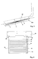
- the step members 5 extend diagonally to the bolts 4 assigned to them in the two rockers 2 and 3. That is, the arrangement of the tread member on the eyelets 4a is such that the tread member is attached to one side of the one eyelet and to the other side of the other eyelet of the respective rocker 2, 3. This ensures that in the folded state shown in FIG. 3, the individual step members 5 abut each other directly. This means that this type of attachment of the treads on the eyelets leads to a space-saving design of the tread in the folded state.
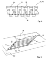
- FIG. 4 With respect to the second variant, reference is now made to Figures 4 and 5.
- two rockers 12, 13 are provided which serve to receive bolts 14. Again, the wings in cross-section U-shaped profile. The bolts are held by the legs of the wings, as can be seen in FIG. 4, but also in FIG.
- alternately support members 16 are provided in the tread members, wherein the tread members 15 are supported on the support members 16, as this results directly in view of FIG.
- Fig. 6 shows the tread of Figure 4 in the retracted state.
- the depth of the retracted stage is greater than in the first variant.
- this level is inherently more stable.
- FIG. 7 it can be seen how the wings of each variant are fixed to the floor of the vehicle.
- the designated 20 plate which is connected to the bottom of the vehicle, has a threaded sleeve 21 which is welded to the floor of the vehicle.
- a cross-sectionally double T-shaped plastic sleeve 22 To the threaded sleeve 21 around is a cross-sectionally double T-shaped plastic sleeve 22, wherein between the legs of the double T-shaped sleeve 22, the total of 2, 3 and 12, 13 labeled swingarm superimposed.
- To apply a moment on the rocker which is the case when z. B.
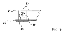
- a spindle drive 30 is provided, as can be seen by way of example from FIG. 1 in conjunction with FIGS. 8 and 9.
- a bolt 33 is pivotally receivable, wherein the bolt 33 in the middle has a threaded bore 34 for the spindle 35 .
- the spindle drive itself shows the number 36.
- the spindle drive 36 is also pivotally mounted on the plate 20 for the bottom of the vehicle, since it pivots when pulling or pulling the spindle.
- the tread is, optionally together with the drive, arranged in a housing 20a under the vehicle floor 20 in order to protect the step from dirt and weathering.
Landscapes
- Health & Medical Sciences (AREA)
- Public Health (AREA)
- Life Sciences & Earth Sciences (AREA)
- Animal Behavior & Ethology (AREA)
- General Health & Medical Sciences (AREA)
- Veterinary Medicine (AREA)
- Engineering & Computer Science (AREA)
- Mechanical Engineering (AREA)
- Vehicle Step Arrangements And Article Storage (AREA)
- Body Structure For Vehicles (AREA)
Applications Claiming Priority (1)
| Application Number | Priority Date | Filing Date | Title |
|---|---|---|---|
| DE102005062142A DE102005062142B3 (de) | 2005-12-22 | 2005-12-22 | Ausstellbare Trittstufe eines Fahrzeuges |
Publications (1)
| Publication Number | Publication Date |
|---|---|
| EP1800640A1 true EP1800640A1 (fr) | 2007-06-27 |
Family
ID=38268407
Family Applications (1)
| Application Number | Title | Priority Date | Filing Date |
|---|---|---|---|
| EP06024886A Withdrawn EP1800640A1 (fr) | 2005-12-22 | 2006-12-01 | Marchepied pivotant de véhicule automobile |
Country Status (2)
| Country | Link |
|---|---|
| EP (1) | EP1800640A1 (fr) |
| DE (1) | DE102005062142B3 (fr) |
Cited By (2)
| Publication number | Priority date | Publication date | Assignee | Title |
|---|---|---|---|---|
| EP2044916B2 (fr) † | 2007-10-05 | 2015-12-09 | Gebr. Bode GmbH & Co. KG | Dispositif de marchepieds |
| EP4212391A1 (fr) * | 2022-01-17 | 2023-07-19 | Volvo Truck Corporation | Ensemble marchepied pliante pour véhicule industriel |
Families Citing this family (3)
| Publication number | Priority date | Publication date | Assignee | Title |
|---|---|---|---|---|
| CN101376355B (zh) * | 2007-08-29 | 2012-04-18 | 卡特彼勒公司 | 具有高度调节阶梯的机装梯子 |
| DE102015213650A1 (de) * | 2015-07-20 | 2017-01-26 | Bombardier Transportation Gmbh | Schienenfahrzeug mit Brückenelement zur Spaltüberbrückung zwischen einer Tür und einem Bahnsteig |
| DE102019213244B4 (de) * | 2019-09-02 | 2024-05-08 | Volkswagen Aktiengesellschaft | Ausfahrbare Plattform und Kraftfahrzeug mit einer ausfahrbaren Plattform |
Citations (5)
| Publication number | Priority date | Publication date | Assignee | Title |
|---|---|---|---|---|
| US533209A (en) * | 1895-01-29 | Skid for- -railway-cars | ||
| US3516515A (en) * | 1968-10-15 | 1970-06-23 | Douglas Keith Clash | Foldable step structure for campers |
| DE8711088U1 (fr) * | 1987-08-14 | 1987-10-08 | Binz Gmbh & Co, 7073 Lorch, De | |
| US5199731A (en) * | 1990-09-04 | 1993-04-06 | Martin Samuel K | Step assembly for vehicles |
| WO2006078195A1 (fr) * | 2005-01-21 | 2006-07-27 | Volvo Lastvagnar Ab | Marchepied pour vehicule |
Family Cites Families (1)
| Publication number | Priority date | Publication date | Assignee | Title |
|---|---|---|---|---|
| ES2107699T3 (es) * | 1994-02-25 | 1997-12-01 | Huebner Gummi & Kunststoff | Pasarela articulada, en diagonal, movil, como parte de una intercomunicacion entre dos vehiculos. |
-
2005
- 2005-12-22 DE DE102005062142A patent/DE102005062142B3/de not_active Expired - Fee Related
-
2006
- 2006-12-01 EP EP06024886A patent/EP1800640A1/fr not_active Withdrawn
Patent Citations (5)
| Publication number | Priority date | Publication date | Assignee | Title |
|---|---|---|---|---|
| US533209A (en) * | 1895-01-29 | Skid for- -railway-cars | ||
| US3516515A (en) * | 1968-10-15 | 1970-06-23 | Douglas Keith Clash | Foldable step structure for campers |
| DE8711088U1 (fr) * | 1987-08-14 | 1987-10-08 | Binz Gmbh & Co, 7073 Lorch, De | |
| US5199731A (en) * | 1990-09-04 | 1993-04-06 | Martin Samuel K | Step assembly for vehicles |
| WO2006078195A1 (fr) * | 2005-01-21 | 2006-07-27 | Volvo Lastvagnar Ab | Marchepied pour vehicule |
Cited By (2)
| Publication number | Priority date | Publication date | Assignee | Title |
|---|---|---|---|---|
| EP2044916B2 (fr) † | 2007-10-05 | 2015-12-09 | Gebr. Bode GmbH & Co. KG | Dispositif de marchepieds |
| EP4212391A1 (fr) * | 2022-01-17 | 2023-07-19 | Volvo Truck Corporation | Ensemble marchepied pliante pour véhicule industriel |
Also Published As
| Publication number | Publication date |
|---|---|
| DE102005062142B3 (de) | 2007-08-02 |
Similar Documents
| Publication | Publication Date | Title |
|---|---|---|
| EP2815681B1 (fr) | Mécanisme de réglage destiné à régler les parties mobiles d'un meuble | |
| EP2070499B1 (fr) | Dispositif de levage de fauteuil roulant | |
| EP2885587B1 (fr) | Construction porteuse pour modules solaire | |
| EP1836070B1 (fr) | Siege de vehicule | |
| EP3108864B1 (fr) | Fauteuil roulant pliable | |
| DE102010052619A1 (de) | Fahrzeugsitz mit geführten Scherenarmen | |
| DE10307149A1 (de) | Klappbarer Fahrzeugsitz | |
| DE102006050662B3 (de) | Kraftfahrzeugtürscharnier | |
| DE102016009038B4 (de) | Klappspitzen-Anlenkstück und Verfahren zum Montieren einer Klappspitze | |
| EP1800640A1 (fr) | Marchepied pivotant de véhicule automobile | |
| DE19920386C2 (de) | Lager für eine umklappbare Rückenlehne | |
| EP0356761A1 (fr) | Dispositif de levage à ciseaux, en particulier pour une plate-forme de travail | |
| EP3656960A2 (fr) | Cinématique pour volet de véhicule | |
| EP1323871B1 (fr) | Dispositif de stabilisation pour engins de travaux tels des pelles hydrauliques ou analogues | |
| DE102008004998A1 (de) | Höhenverstellbarer Fahrzeugsitz mit einer Memory-Funktion | |
| DE102007024570B4 (de) | Scharnier für eine Kraftfahrzeugtür | |
| EP2740872B1 (fr) | Palier d'angle prévu pour l'agencement recouvert | |
| DE4342402A1 (de) | Antriebs- und Riegelmechanismus für einen geradlinig ausfahrbaren Überrollbügel | |
| DE102009044220B4 (de) | Kamerawagen | |
| DE102015008649A1 (de) | Fahrzeugsitz und Fahrzeug | |
| EP3748099B1 (fr) | Marquise | |
| DE102010018664B4 (de) | Vorrichtung zur Anbindung eines Fahrzeugsitzes an eine Dreheinheit, Dreheinheit und Fahrzeugsitz | |
| AT13451U1 (de) | Brücke zwischen zwei gelenkig miteinander verbundenen Fahrzeugteilen | |
| DE102009006847B4 (de) | Verkaufswagen | |
| DE102017215282A1 (de) | Vordachbaueinheit |
Legal Events
| Date | Code | Title | Description |
|---|---|---|---|
| PUAI | Public reference made under article 153(3) epc to a published international application that has entered the european phase |
Free format text: ORIGINAL CODE: 0009012 |
|
| AK | Designated contracting states |
Kind code of ref document: A1 Designated state(s): AT BE BG CH CY CZ DE DK EE ES FI FR GB GR HU IE IS IT LI LT LU LV MC NL PL PT RO SE SI SK TR |
|
| AX | Request for extension of the european patent |
Extension state: AL BA HR MK YU |
|
| AKX | Designation fees paid | ||
| STAA | Information on the status of an ep patent application or granted ep patent |
Free format text: STATUS: THE APPLICATION IS DEEMED TO BE WITHDRAWN |
|
| 18D | Application deemed to be withdrawn |
Effective date: 20071228 |
|
| REG | Reference to a national code |
Ref country code: DE Ref legal event code: 8566 |