EP1836070B1 - Siege de vehicule - Google Patents
Siege de vehicule Download PDFInfo
- Publication number
- EP1836070B1 EP1836070B1 EP05815814A EP05815814A EP1836070B1 EP 1836070 B1 EP1836070 B1 EP 1836070B1 EP 05815814 A EP05815814 A EP 05815814A EP 05815814 A EP05815814 A EP 05815814A EP 1836070 B1 EP1836070 B1 EP 1836070B1
- Authority
- EP
- European Patent Office
- Prior art keywords
- backrest
- vehicle seat
- holding arms
- arms
- seat according
- Prior art date
- Legal status (The legal status is an assumption and is not a legal conclusion. Google has not performed a legal analysis and makes no representation as to the accuracy of the status listed.)
- Expired - Lifetime
Links
Images
Classifications
-
- B—PERFORMING OPERATIONS; TRANSPORTING
- B60—VEHICLES IN GENERAL
- B60N—SEATS SPECIALLY ADAPTED FOR VEHICLES; VEHICLE PASSENGER ACCOMMODATION NOT OTHERWISE PROVIDED FOR
- B60N2/00—Seats specially adapted for vehicles; Arrangement or mounting of seats in vehicles
- B60N2/90—Details or parts not otherwise provided for
- B60N2/986—Side-rests
- B60N2/99—Side-rests adjustable
-
- A—HUMAN NECESSITIES
- A47—FURNITURE; DOMESTIC ARTICLES OR APPLIANCES; COFFEE MILLS; SPICE MILLS; SUCTION CLEANERS IN GENERAL
- A47C—CHAIRS; SOFAS; BEDS
- A47C7/00—Parts, details, or accessories of chairs or stools
- A47C7/36—Supports for the head or the back
- A47C7/40—Supports for the head or the back for the back
- A47C7/405—Supports for the head or the back for the back with double backrests
-
- B—PERFORMING OPERATIONS; TRANSPORTING
- B60—VEHICLES IN GENERAL
- B60N—SEATS SPECIALLY ADAPTED FOR VEHICLES; VEHICLE PASSENGER ACCOMMODATION NOT OTHERWISE PROVIDED FOR
- B60N2/00—Seats specially adapted for vehicles; Arrangement or mounting of seats in vehicles
- B60N2/02—Seats specially adapted for vehicles; Arrangement or mounting of seats in vehicles the seat or part thereof being movable, e.g. adjustable
- B60N2/0224—Non-manual adjustments, e.g. with electrical operation
- B60N2/02246—Electric motors therefor
- B60N2/02253—Electric motors therefor characterised by the transmission between the electric motor and the seat or seat parts
-
- B—PERFORMING OPERATIONS; TRANSPORTING
- B60—VEHICLES IN GENERAL
- B60N—SEATS SPECIALLY ADAPTED FOR VEHICLES; VEHICLE PASSENGER ACCOMMODATION NOT OTHERWISE PROVIDED FOR
- B60N2/00—Seats specially adapted for vehicles; Arrangement or mounting of seats in vehicles
- B60N2/02—Seats specially adapted for vehicles; Arrangement or mounting of seats in vehicles the seat or part thereof being movable, e.g. adjustable
- B60N2/0224—Non-manual adjustments, e.g. with electrical operation
- B60N2/02246—Electric motors therefor
- B60N2/02258—Electric motors therefor characterised by the mounting of the electric motor for adjusting the seat
-
- B—PERFORMING OPERATIONS; TRANSPORTING
- B60—VEHICLES IN GENERAL
- B60N—SEATS SPECIALLY ADAPTED FOR VEHICLES; VEHICLE PASSENGER ACCOMMODATION NOT OTHERWISE PROVIDED FOR
- B60N2/00—Seats specially adapted for vehicles; Arrangement or mounting of seats in vehicles
- B60N2/02—Seats specially adapted for vehicles; Arrangement or mounting of seats in vehicles the seat or part thereof being movable, e.g. adjustable
- B60N2/0224—Non-manual adjustments, e.g. with electrical operation
- B60N2/0244—Non-manual adjustments, e.g. with electrical operation with logic circuits
- B60N2/026—Non-manual adjustments, e.g. with electrical operation with logic circuits varying hardness or support of upholstery, e.g. for tuning seat comfort when driving curved roads
-
- B—PERFORMING OPERATIONS; TRANSPORTING
- B60—VEHICLES IN GENERAL
- B60N—SEATS SPECIALLY ADAPTED FOR VEHICLES; VEHICLE PASSENGER ACCOMMODATION NOT OTHERWISE PROVIDED FOR
- B60N2/00—Seats specially adapted for vehicles; Arrangement or mounting of seats in vehicles
- B60N2/02—Seats specially adapted for vehicles; Arrangement or mounting of seats in vehicles the seat or part thereof being movable, e.g. adjustable
- B60N2/22—Seats specially adapted for vehicles; Arrangement or mounting of seats in vehicles the seat or part thereof being movable, e.g. adjustable the back-rest being adjustable
- B60N2/2222—Seats specially adapted for vehicles; Arrangement or mounting of seats in vehicles the seat or part thereof being movable, e.g. adjustable the back-rest being adjustable the back-rest having two or more parts
-
- B—PERFORMING OPERATIONS; TRANSPORTING
- B60—VEHICLES IN GENERAL
- B60N—SEATS SPECIALLY ADAPTED FOR VEHICLES; VEHICLE PASSENGER ACCOMMODATION NOT OTHERWISE PROVIDED FOR
- B60N2/00—Seats specially adapted for vehicles; Arrangement or mounting of seats in vehicles
- B60N2/64—Back-rests or cushions
- B60N2/643—Back-rests or cushions shape of the back-rests
-
- B—PERFORMING OPERATIONS; TRANSPORTING
- B60—VEHICLES IN GENERAL
- B60N—SEATS SPECIALLY ADAPTED FOR VEHICLES; VEHICLE PASSENGER ACCOMMODATION NOT OTHERWISE PROVIDED FOR
- B60N2205/00—General mechanical or structural details
- B60N2205/30—Seat or seat parts characterised by comprising plural parts or pieces
Definitions
- the invention relates to a vehicle seat with a backrest specified in the preamble of claim 1. Art.
- the FR 2 602 133 A which corresponds to the preamble of claim 1, shows a dynamic seat frame for a vehicle having a backrest body, the inclination of which can be adapted to the acceleration and the wishes of the occupant.
- this vehicle seat comprises a seat support structure and a back frame, which has two bearings at the ends, rotatably mounted on the backrest body, so that it can pivot about a horizontal axis.
- a disadvantage of such a seat is the fact that further adjustments, for example, to the height of the occupant are not possible.
- a seat support member comprising two plate-like side members and a generally flexible interconnecting intermediate body which extends in a bridge fashion between the inboard ends of the side members.
- the seat structures described above are rather unsuitable for use in motor vehicles.
- German patent DE 37 07 926 C2 a vehicle seat with a backrest is known, which has as a structural component a shell mold with central part and thus integral, forward laterally wegstrebenden side guide members. The shell is adapted to the back width of a medium to large seat occupant.
- the side guide members are formed resiliently pivotable relative to the central part and suspended from a substantially rigid backrest frame, that in persons who are narrower than the constructive predetermined width of the shell mold, the side guide parts to move towards each other with back displacement of the middle part.
- German patent DE 39 10 143 C2 is a motor vehicle seat with a backrest and a pair of side supports known, which are pivotally connected via respective pivot shafts with both sides of the backrest.
- the object of the invention is to provide a vehicle seat of the aforementioned type, with which further adjustments, for example, to the height of the occupant are possible.
- the backrest is articulated at its end facing the seat to the seat support structure. As a result, an adjustment of the inclination or a folding of the backrest is made possible.
- the backrest In operation, the backrest, based on the articulation on the seat facing the end, fixed.
- the backrest about the horizontal axis of rotation which is preferably arranged at the level of the upper pool edge support, free or against the biasing force of at least one spring means rotatable by a limited angle of rotation. This allows a frequent change in the load on the intervertebral discs. Due to the mounting of the backrest main body in the backrest frame, a stable mounting of the backrest main body is made possible, which allows an active sitting even with high lateral acceleration forces, such as occur during operation of a motor vehicle.
- the vehicle seat is characterized in that the two bearing devices are displaceably guided in each case on a guide rail attached to the backrest frame in the longitudinal direction of the backrest.
- a height adjustment of the horizontal axis of rotation is made possible in a simple manner.
- a further preferred embodiment of the vehicle seat is characterized in that above the two storage facilities, two further storage facilities for the backrest main body are attached to the back frame, each having a rotation limiting element, which is guided in a slot.
- the angle of rotation of the backrest base body relative to the backrest frame about the horizontal Limited rotation is biased by at least one spring means in a middle position.
- a further preferred embodiment of the vehicle seat is characterized in that the backrest is divided in the longitudinal direction and has two backrest shells, which are attached to a plurality of substantially horizontally extending support arms.
- the two backrests allow a uniform enclosure of the upper body and the waist of a person sitting on the vehicle seat.
- a further preferred embodiment of the vehicle seat is characterized in that the retaining arms comprise a lower, an upper and a middle pair of holding arms, which is arranged between the lower and the upper pair of holding arms viewed in the longitudinal direction of the backrest.
- the three holding arm pairs allow individual adjustment of the backrest shells without affecting the stability of the storage.
- a further preferred embodiment of the vehicle seat is characterized in that a support arm in the longitudinal direction of the support arms is guided in each case displaceably on the support arms of the lower and the upper pair of retaining arms. This allows a shift of the bearing shells across each other.
- a further preferred embodiment of the vehicle seat is characterized in that at the ends of the support arms of the lower and the upper pair of holding arms, in each case a fastening element is articulated.
- a fastening element is articulated at the ends of the support arms of the lower and the upper pair of holding arms.
- a further preferred embodiment of the vehicle seat is characterized in that in the holding arms of the middle pair of holding arms in each case a guide shoe in the longitudinal direction of the support arms is displaceably guided, to which a lever arm is articulated.
- the guide shoes allow the displacement of the bearing shells across each other.
- vehicle seat is characterized in that at the ends of the lever arms in each case a fastening element is articulated. This allows a defined rotation of the bearing shells about the vertical axes of rotation.
- a further preferred embodiment of the vehicle seat is characterized in that the holding arms of a pair of holding arms are arranged at an obtuse angle to each other.
- the holding arm pairs are each firmly connected to the backrest main body.
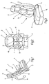
- the vehicle seat 1 has a backrest 2 and a seat surface 3.
- the backrest 2 comprises a backrest frame 5, which is mounted pivotably about a rotation axis 7 on a seat support structure 9, on which the vehicle seat surface 3 is also attached.
- the backrest 2 is divided into two backrest shells 11, 12, which are attached to the backrest frame 5.
- a headrest 13 is attached to the backrest frame 5.
- FIG. 1 is indicated by a double arrow 14, that the backrest shells 11, 12 are displaceable in the longitudinal direction of the backrest frame 5.
- a displacement of the backrest shells 11, 12 in the direction of the double arrow 14 serves to adapt the backrests 2 to the shape of a vehicle occupant.
- FIG. 1 indicated that the backrest shells 11, 12 are limited pivotally about an axis of rotation 15, as indicated by a double arrow 16.
- a pivoting of the backrest shells 11, 12 about the axis of rotation 15 is preferably carried out against the biasing force of at least one (not shown) spring means.
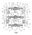
- FIG. 2 is indicated that the backrest shells 11, 12 are further rotatable about two axes of rotation 18, 19.
- the corresponding movement of the backrest shells 11, 12 about the axes of rotation 18, 19 is indicated by double arrows 21, 22.
- FIG. 3 is indicated by a double arrow 24 that the two backrest shells 11, 12 are also mounted transversely to each other displaceable on the back frame 5.
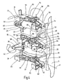
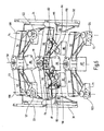
- FIGS. 4 to 6 is the inner structure of the in the FIGS. 1 to 3 illustrated vehicle seat 1 shown in various views in perspective.
- the backrest frame 5 is shown only schematically in partial detail.
- the backrest frame 5 may be closed or open, for example U-shaped.
- four guide rails 31, 32, 33, 34 are attached on the back frame 5.
- the guide rails 31 to 34 are arranged substantially in the longitudinal direction of the backrest.
- the two guide rails 31, 32 are arranged in the lower half of the backrest on two opposite sides and form a lower guide rail pair.
- the two guide rails 33, 34 are arranged in the upper half of the backrest on two opposite sides and form an upper guide rail pair.
- a bearing block 36, 37 On the guide rails 31, 32 are each a bearing block 36, 37 slidably guided in the longitudinal direction.
- a bearing block 36, 37 together with a bearing support 38, 39 each have a bearing device for a bearing body.
- the bearing supports 38, 39 are fixed to the bearing body 40.
- the attachment is preferably detachable, for example by screw.
- the bearing devices each formed by a bearing block 36, 37 and a bearing support 38, 39 allow the backrest base body 40 to be rotated about a rotation axis 41.
- An arrow 42 causes a rotational movement of the bearing element Lehnengrund stresses 40 indicated about the axis of rotation 41.
- the rotation of the backrest main body 40 can take place in both directions of rotation about the axis of rotation 41 around.
- each bearing block 44, 45 slidably guided in the longitudinal direction. From the free end of the bearing blocks 44, 45 is in each case a guide element from inside.
- the guide element is formed by a screw bolt 46 which is fixed at one end to the bearing block 44.
- the bolt 46 may, for example, be screwed into a correspondingly formed threaded bore in the bearing block 44.
- a screw head is provided at the other end of the bolt 46.
- the bolt 46 extends through a slot 48 which is recessed in a bearing support 49.
- the bearing support 49 and a mirror-like analog bearing support 50 are attached to the backrest body 40. Due to the elongated holes in the bearing supports 49, 50, the angle of rotation when rotating the backrest main body 40 about the axis of rotation 41 is limited.
- the support arms 51 to 56 are attached in addition to the bearing supports 38, 39, 49, 50.
- the support arms 51 to 56 are arranged in pairs horizontally and at an obtuse angle of about 160 degrees to each other.
- the holding arms 51, 52 form a lower pair of holding arms.
- the holding arms 53, 54 form an upper holding pair.
- a middle pair of holding arms is arranged, which is formed by the holding arms 55, 56.
- the holding arms 51 to 56 are arranged so that they abut each other in pairs in the region of a central axis 58. In the region of the joint they are attached to the backrest body 40.
- each of the holding arms 51 to 54 one end of a support arm 61 to 64 is slidably guided in the longitudinal direction of the holding arms.
- a fastener 71 to 74 is articulated.
- the fastening elements 71 to 74 serve for the attachment of backrest shells (not shown in FIG. 4).
- a respective guide shoe 81, 82 is guided displaceably in the longitudinal direction of the support arms.
- To the guide shoes 81, 82 each have one end of a lever arm 83, 84 articulated.
- At the other end of the lever arms 83,84 each have a fastener 85, 86 articulated.
- the fastening elements 71, 73, 85 serve for fastening a first backrest shell.
- the fastening elements 72, 74, 86 serve for fastening a second back shell.
- FIG. 5 is indicated by arrows 101 to 104, that the backrest base body 40 is slidable with the holding arms 51 to 56 attached thereto in height.
- a shift which can of course take place in both directions, in particular the height of the horizontal axis of rotation (41 in FIG. 4 ) are adjusted.
- a rotation of the motor shaft associated with the motor 88 in the direction of an arrow 111 causes the guide shoes 81, 82 in the retaining arms 55, 56 to move outward, as indicated by arrows 114, 115.
- This movement in turn causes the fasteners 85, 86 rotate with the backrest shells attached thereto in the direction of arrows 118, 119.
- These movements in turn cause the fastening elements 71 to 74 to rotate together with the backrest shells attached thereto about the axes of rotation 108, 109, as indicated by arrows 121 to 124.
Landscapes
- Engineering & Computer Science (AREA)
- Aviation & Aerospace Engineering (AREA)
- Transportation (AREA)
- Mechanical Engineering (AREA)
- Seats For Vehicles (AREA)
- Chairs For Special Purposes, Such As Reclining Chairs (AREA)
Abstract
Claims (9)
- Siège de véhicule avec un dossier (2),■ qui présente un cadre de dossier (5) qui est monté sur une structure porteuse de siège (9),■ et qui peut être pivoté de manière limitée autour d'un axe de rotation (15 ; 41) horizontal afin de permettre une assise active,caractérisé en ce que
dans lequel deux ensembles de palier (36-39) sont montés sur le cadre de dossier (5), sur lesquels est logé à rotation un corps de base de dossier (40) autour de l'axe de rotation (41) horizontal,
les deux ensembles de palier (36-39) sont guidés en déplacement sur respectivement un rail de guidage (31, 32) monté sur le cadre de dossier (5) dans le sens longitudinal du dossier (2). - Siège de véhicule selon la revendication 1, caractérisé en ce que au-dessus des deux ensembles de palier (36-39) sont montés deux autres ensembles de palier (44, 45, 49, 50) pour le corps de base de dossier (40) sur le cadre de dossier (5), lesquels présentent respectivement un élément de limitation de rotation (46) qui est guidé dans un trou oblong (48).
- Siège de véhicule selon l'une quelconque des revendications précédentes, caractérisé en ce que le dossier (2) est scindé dans le sens longitudinal et présente deux coques de dossier (11, 12) qui sont montées sur plusieurs bras de support (51-56) s'étendant sensiblement horizontalement.
- Siège de véhicule selon la revendication 3, caractérisé en ce que les bras de support (51-56) comportent une paire de bras de support inférieure, une paire de bras de support supérieure et une paire de bras de support médiane qui est disposée, considérée dans le sens longitudinal du dossier (2), entre la paire de bras de support inférieure et la paire de bras de support supérieure.
- Siège de véhicule selon la revendication 4, caractérisé en ce que respectivement un bras porteur (61-64) est guidé en déplacement dans le sens longitudinal des bras de support sur les bras de support (51-54) de la paire de bras de support inférieure et de la paire de bras de support supérieure.
- Siège de véhicule selon la revendication 5, caractérisé en ce que respectivement un élément de fixation (71-74) est articulé sur les extrémités des bras porteurs (51-54) de la paire de bras de support inférieure et de la paire de bras de support supérieure.
- Siège de véhicule selon l'une quelconque des revendications 4 à 6, caractérisé en ce que respectivement une griffe de guidage (81, 82) est guidée en déplacement dans le sens longitudinal des bras de support (55, 56) sur les bras de support de la paire de bras de support médiane, sur laquelle est articulé un bras de levier (93, 84).
- Siège de véhicule selon la revendication 7, caractérisé en ce que respectivement un élément de fixation (85, 86) est articulé sur les extrémités des bras de levier (83, 84).
- Siège de véhicule selon l'une quelconque des revendications 4 à 8, caractérisé en ce que les bras de support (51-56) d'une paire de bras de support sont disposés dans un angle obtus les uns par rapport aux autres.
Applications Claiming Priority (2)
| Application Number | Priority Date | Filing Date | Title |
|---|---|---|---|
| DE102005001960A DE102005001960A1 (de) | 2005-01-15 | 2005-01-15 | Fahrzeugsitz |
| PCT/EP2005/013351 WO2006074780A1 (fr) | 2005-01-15 | 2005-12-13 | Siege de vehicule |
Publications (2)
| Publication Number | Publication Date |
|---|---|
| EP1836070A1 EP1836070A1 (fr) | 2007-09-26 |
| EP1836070B1 true EP1836070B1 (fr) | 2008-12-10 |
Family
ID=35853184
Family Applications (1)
| Application Number | Title | Priority Date | Filing Date |
|---|---|---|---|
| EP05815814A Expired - Lifetime EP1836070B1 (fr) | 2005-01-15 | 2005-12-13 | Siege de vehicule |
Country Status (5)
| Country | Link |
|---|---|
| US (1) | US20090102264A1 (fr) |
| EP (1) | EP1836070B1 (fr) |
| JP (1) | JP2008526611A (fr) |
| DE (2) | DE102005001960A1 (fr) |
| WO (1) | WO2006074780A1 (fr) |
Families Citing this family (14)
| Publication number | Priority date | Publication date | Assignee | Title |
|---|---|---|---|---|
| FR2899850B1 (fr) * | 2006-04-13 | 2008-06-20 | Faurecia Sieges Automobile | Siege a ailes mobiles |
| US8251441B2 (en) | 2010-08-20 | 2012-08-28 | Barbara Elisabeth Alink | Chair |
| CN103072501A (zh) * | 2013-01-05 | 2013-05-01 | 好孩子儿童用品有限公司 | 一种座椅靠背及具有该靠背的汽车座 |
| DE102013106721B3 (de) * | 2013-06-26 | 2014-10-30 | Grammer Ag | Fahrzeugsitz und Nutzkraftfahrzeug mit wenigstens einem Fahrzeugsitz |
| JP5855614B2 (ja) * | 2013-09-02 | 2016-02-09 | トヨタ紡織株式会社 | 車両用シート |
| DE202013011803U1 (de) | 2013-12-04 | 2015-03-11 | Brose Fahrzeugteile Gmbh & Co. Kommanditgesellschaft, Coburg | Fahrzeugsitz mit einer Verriegelungsvorrichtung für eine in sich verdrehbare Rückenlehne |
| DE102013224873A1 (de) * | 2013-12-04 | 2015-06-25 | Brose Fahrzeugteile Gmbh & Co. Kg, Coburg | Fahrzeugsitz mit einer Verriegelungsvorrichtung für eine in sich verdrehbare Rückenlehne |
| JP6098576B2 (ja) * | 2014-06-20 | 2017-03-22 | トヨタ自動車株式会社 | 車両用シート |
| DE102016204067A1 (de) * | 2016-03-11 | 2017-09-14 | Brose Fahrzeugteile Gmbh & Co. Kg, Coburg | Vorrichtung zum Verstellen zumindest einer Seitenwange eines Sitzteils und/oder einer Rückenlehne eines Fahrzeugsitzes |
| WO2018197915A1 (fr) * | 2017-04-28 | 2018-11-01 | Zimmermann Juergen | Siège |
| DE102017004415B4 (de) | 2017-05-05 | 2022-10-13 | Audi Ag | Fahrzeugsitz für ein Kraftfahrzeug, Sitzvorrichtung für ein Kraftfahrzeug, Kraftfahrzeug und Verfahren zum Verstellen eines Fahrzeugsitzes |
| JP7099933B2 (ja) * | 2018-11-01 | 2022-07-12 | トヨタ自動車株式会社 | 車両用シート |
| US11161615B2 (en) | 2019-11-15 | 2021-11-02 | B/E Aerospace, Inc. | Staggered pneumatic articulation system for seat back deployment and comfort |
| IT202200014446A1 (it) * | 2022-07-08 | 2024-01-08 | Ferrari Spa | Autoveicolo con assieme di sedile diviso in piu' porzioni singolarmente regolabili |
Family Cites Families (16)
| Publication number | Priority date | Publication date | Assignee | Title |
|---|---|---|---|---|
| DE8337429U1 (de) * | 1984-04-05 | Adam Opel AG, 6090 Rüsselsheim | Sitz für Fahrzeuge, insbesondere Kraftfahrzeuge | |
| GB1406246A (en) * | 1972-02-02 | 1975-09-17 | Ipeco Europ Ltd | Seats with back support |
| EP0107627B1 (fr) * | 1982-10-22 | 1986-01-02 | Castelli S.P.A. | Chaise dont le dossier comporte plusieurs segments articulés |
| JPH064044B2 (ja) * | 1985-02-21 | 1994-01-19 | 本田技研工業株式会社 | 車両等の座席 |
| FR2602133B1 (fr) * | 1986-08-01 | 1988-10-21 | Boulay Maurice | Siege dynamique dont l'inclinaison du dossier et de l'appui-tete varie en fonction des accelerations et decelerations du vehicule |
| DE3707926A1 (de) * | 1987-03-12 | 1988-09-22 | Daimler Benz Ag | Sitz, insbesondere fahrzeugsitz |
| JPH0517973Y2 (fr) * | 1988-03-31 | 1993-05-13 | ||
| IT1223725B (it) * | 1988-07-25 | 1990-09-29 | Sicam Linea Srl | Sedile di autoveicolo |
| DE9006316U1 (de) * | 1990-06-05 | 1990-08-16 | "Aura" Herbert D. Stolle GmbH & Co, 2000 Hamburg | Rückenlehne |
| IT225507Y1 (it) * | 1991-10-18 | 1996-11-18 | Clerprem Spa | Elemento di supporto per sedili utilizzabile ad esempio quale elemento di supporto lombare per schienali di sedili automobilistici |
| US5558399A (en) * | 1994-09-13 | 1996-09-24 | Serber; Hector | Seat and lumbar motion chair, assembly and method |
| US5938284A (en) * | 1996-07-19 | 1999-08-17 | Cascade Engineering, Inc. | Seat bolster adjustment assembly |
| DE10057449A1 (de) * | 2000-11-20 | 2002-05-29 | Lear Corp Gmbh & Co Kg | Seitenwange für einen Sitz |
| US6530622B1 (en) * | 2001-03-16 | 2003-03-11 | Johnson Controls Technology Company | Biomechanical vehicle seat |
| DE102004017656A1 (de) * | 2003-04-25 | 2004-11-25 | Volkswagen Ag | Fahrzeugsitz |
| DE102005017634B4 (de) * | 2005-04-15 | 2008-04-17 | Grammer Ag | Fahrzeugsitz mit verformbarer S-förmiger Rückenlehne |
-
2005
- 2005-01-15 DE DE102005001960A patent/DE102005001960A1/de not_active Ceased
- 2005-12-13 DE DE502005006238T patent/DE502005006238D1/de not_active Expired - Lifetime
- 2005-12-13 US US11/795,203 patent/US20090102264A1/en not_active Abandoned
- 2005-12-13 JP JP2007550698A patent/JP2008526611A/ja not_active Abandoned
- 2005-12-13 WO PCT/EP2005/013351 patent/WO2006074780A1/fr not_active Ceased
- 2005-12-13 EP EP05815814A patent/EP1836070B1/fr not_active Expired - Lifetime
Also Published As
| Publication number | Publication date |
|---|---|
| US20090102264A1 (en) | 2009-04-23 |
| EP1836070A1 (fr) | 2007-09-26 |
| WO2006074780A1 (fr) | 2006-07-20 |
| DE502005006238D1 (de) | 2009-01-22 |
| JP2008526611A (ja) | 2008-07-24 |
| DE102005001960A1 (de) | 2006-07-20 |
Similar Documents
| Publication | Publication Date | Title |
|---|---|---|
| DE102007049864B4 (de) | Sitzgestell eines Kraftfahrzeugsitzes mit einem Sitzträger, der zwei Seitenteile hat | |
| DE102014107816B4 (de) | Nutzfahrzeugsitz mit arretierbarem Querschlittenteil | |
| EP0842844B1 (fr) | Siège de véhicule | |
| DE3817761C2 (fr) | ||
| EP1836070B1 (fr) | Siege de vehicule | |
| EP2337704B1 (fr) | Châssis de siège de véhicule automobile avec deux paires de rails, des bielles et un support de siège | |
| EP3953211B1 (fr) | Siège de véhicule | |
| EP3626523B1 (fr) | Siège de véhicule pour cabines des véhicules utilitaires | |
| EP2707250B1 (fr) | Siège de véhicule, en particulier siège de véhicule automobile | |
| DE10012590B4 (de) | Vor einem Laderaum eines Kraftfahrzeuges angeordnete Sitzanordnung | |
| DE102019122542A1 (de) | Fahrzeugsitz für Nutzfahrzeugkabinen | |
| EP1360085B1 (fr) | Siège, en particulier siège de véhicule, de préférence siège passager d'avion | |
| EP1291232B1 (fr) | Châssis de siège de véhicules automobiles avec un support de siège et bras avant de parallélogramme | |
| DE102005017634B4 (de) | Fahrzeugsitz mit verformbarer S-förmiger Rückenlehne | |
| DE19920386C2 (de) | Lager für eine umklappbare Rückenlehne | |
| EP1632152A2 (fr) | Meuble d'assise | |
| DE19501521A1 (de) | Verstellbarer Fahrzeugsitz | |
| DE102009022625A1 (de) | Klapptischeinrichtung für ein Kraftfahrzeug | |
| WO2000066390A1 (fr) | Palier | |
| DE69714910T2 (de) | Verstellvorrichtung | |
| DE102019108663A1 (de) | Kraftfahrzeugsitz | |
| EP3893696B1 (fr) | Meuble pour s'asseoir comportant un dispositif d'appui dorsolombaire | |
| DE10209560B4 (de) | Bidirektionaler Fahrzeugsitz | |
| DE202017102905U1 (de) | Lattenrost | |
| DE202007010292U1 (de) | Sitzlehne für ein Kraftfahrzeug sowie Kraftfahrzeugsitz |
Legal Events
| Date | Code | Title | Description |
|---|---|---|---|
| PUAI | Public reference made under article 153(3) epc to a published international application that has entered the european phase |
Free format text: ORIGINAL CODE: 0009012 |
|
| 17P | Request for examination filed |
Effective date: 20070621 |
|
| AK | Designated contracting states |
Kind code of ref document: A1 Designated state(s): DE FR GB IT |
|
| 17Q | First examination report despatched |
Effective date: 20071031 |
|
| RAP1 | Party data changed (applicant data changed or rights of an application transferred) |
Owner name: DAIMLER AG |
|
| DAX | Request for extension of the european patent (deleted) | ||
| RBV | Designated contracting states (corrected) |
Designated state(s): DE FR GB IT |
|
| GRAP | Despatch of communication of intention to grant a patent |
Free format text: ORIGINAL CODE: EPIDOSNIGR1 |
|
| GRAS | Grant fee paid |
Free format text: ORIGINAL CODE: EPIDOSNIGR3 |
|
| GRAA | (expected) grant |
Free format text: ORIGINAL CODE: 0009210 |
|
| AK | Designated contracting states |
Kind code of ref document: B1 Designated state(s): DE FR GB IT |
|
| REG | Reference to a national code |
Ref country code: GB Ref legal event code: FG4D Free format text: NOT ENGLISH |
|
| REF | Corresponds to: |
Ref document number: 502005006238 Country of ref document: DE Date of ref document: 20090122 Kind code of ref document: P |
|
| PLBE | No opposition filed within time limit |
Free format text: ORIGINAL CODE: 0009261 |
|
| STAA | Information on the status of an ep patent application or granted ep patent |
Free format text: STATUS: NO OPPOSITION FILED WITHIN TIME LIMIT |
|
| PGFP | Annual fee paid to national office [announced via postgrant information from national office to epo] |
Ref country code: IT Payment date: 20081231 Year of fee payment: 4 |
|
| 26N | No opposition filed |
Effective date: 20090911 |
|
| PGFP | Annual fee paid to national office [announced via postgrant information from national office to epo] |
Ref country code: FR Payment date: 20110104 Year of fee payment: 6 |
|
| PG25 | Lapsed in a contracting state [announced via postgrant information from national office to epo] |
Ref country code: IT Free format text: LAPSE BECAUSE OF NON-PAYMENT OF DUE FEES Effective date: 20091213 |
|
| PGFP | Annual fee paid to national office [announced via postgrant information from national office to epo] |
Ref country code: GB Payment date: 20101221 Year of fee payment: 6 |
|
| GBPC | Gb: european patent ceased through non-payment of renewal fee |
Effective date: 20111213 |
|
| REG | Reference to a national code |
Ref country code: FR Ref legal event code: ST Effective date: 20120831 |
|
| PG25 | Lapsed in a contracting state [announced via postgrant information from national office to epo] |
Ref country code: GB Free format text: LAPSE BECAUSE OF NON-PAYMENT OF DUE FEES Effective date: 20111213 |
|
| PG25 | Lapsed in a contracting state [announced via postgrant information from national office to epo] |
Ref country code: FR Free format text: LAPSE BECAUSE OF NON-PAYMENT OF DUE FEES Effective date: 20120102 |
|
| PGFP | Annual fee paid to national office [announced via postgrant information from national office to epo] |
Ref country code: DE Payment date: 20160302 Year of fee payment: 11 |
|
| REG | Reference to a national code |
Ref country code: DE Ref legal event code: R119 Ref document number: 502005006238 Country of ref document: DE |
|
| PG25 | Lapsed in a contracting state [announced via postgrant information from national office to epo] |
Ref country code: DE Free format text: LAPSE BECAUSE OF NON-PAYMENT OF DUE FEES Effective date: 20170701 |