EP1800640A1 - Pivoting footstep of a vehicle - Google Patents
Pivoting footstep of a vehicle Download PDFInfo
- Publication number
- EP1800640A1 EP1800640A1 EP06024886A EP06024886A EP1800640A1 EP 1800640 A1 EP1800640 A1 EP 1800640A1 EP 06024886 A EP06024886 A EP 06024886A EP 06024886 A EP06024886 A EP 06024886A EP 1800640 A1 EP1800640 A1 EP 1800640A1
- Authority
- EP
- European Patent Office
- Prior art keywords
- tread
- members
- vehicle
- wings
- rockers
- Prior art date
- Legal status (The legal status is an assumption and is not a legal conclusion. Google has not performed a legal analysis and makes no representation as to the accuracy of the status listed.)
- Withdrawn
Links
Images


Classifications
-
- B—PERFORMING OPERATIONS; TRANSPORTING
- B60—VEHICLES IN GENERAL
- B60R—VEHICLES, VEHICLE FITTINGS, OR VEHICLE PARTS, NOT OTHERWISE PROVIDED FOR
- B60R3/00—Arrangements of steps or ladders facilitating access to or on the vehicle, e.g. running-boards
- B60R3/02—Retractable steps or ladders, e.g. movable under shock
-
- A—HUMAN NECESSITIES
- A61—MEDICAL OR VETERINARY SCIENCE; HYGIENE
- A61G—TRANSPORT, PERSONAL CONVEYANCES, OR ACCOMMODATION SPECIALLY ADAPTED FOR PATIENTS OR DISABLED PERSONS; OPERATING TABLES OR CHAIRS; CHAIRS FOR DENTISTRY; FUNERAL DEVICES
- A61G3/00—Ambulance aspects of vehicles; Vehicles with special provisions for transporting patients or disabled persons, or their personal conveyances, e.g. for facilitating access of, or for loading, wheelchairs
- A61G3/02—Loading or unloading personal conveyances; Facilitating access of patients or disabled persons to, or exit from, vehicles
- A61G3/06—Transfer using ramps, lifts or the like
- A61G3/061—Transfer using ramps, lifts or the like using ramps
-
- A—HUMAN NECESSITIES
- A61—MEDICAL OR VETERINARY SCIENCE; HYGIENE
- A61G—TRANSPORT, PERSONAL CONVEYANCES, OR ACCOMMODATION SPECIALLY ADAPTED FOR PATIENTS OR DISABLED PERSONS; OPERATING TABLES OR CHAIRS; CHAIRS FOR DENTISTRY; FUNERAL DEVICES
- A61G3/00—Ambulance aspects of vehicles; Vehicles with special provisions for transporting patients or disabled persons, or their personal conveyances, e.g. for facilitating access of, or for loading, wheelchairs
- A61G3/02—Loading or unloading personal conveyances; Facilitating access of patients or disabled persons to, or exit from, vehicles
- A61G3/06—Transfer using ramps, lifts or the like
- A61G3/067—Transfer using ramps, lifts or the like with compartment for horizontally storing the ramp or lift
-
- B—PERFORMING OPERATIONS; TRANSPORTING
- B61—RAILWAYS
- B61D—BODY DETAILS OR KINDS OF RAILWAY VEHICLES
- B61D23/00—Construction of steps for railway vehicles
- B61D23/02—Folding steps for railway vehicles, e.g. hand or mechanically actuated
- B61D23/025—Folding steps for railway vehicles, e.g. hand or mechanically actuated electrically or fluid actuated
Definitions
- the invention relates to an exhibitable step of a vehicle.
- Deployable steps of a vehicle are well known, for example, in vans, buses but also in motorhomes.
- Known exhibitable treads work on a variety of principles.
- an electric folding stage is known, wherein the stage is usually engaged or disengaged by a lever mechanism and an electric motor.
- a so-called folding stage is known in which the step is swung out of the interior of the vehicle by means of a pivoting movement by almost 180 °.
- so-called sliding steps are known in which the tread is manually or electromechanically on or extendable.
- the invention is therefore based on the object to provide an exposed tread, which is designed to save space.
- the tread should in the folded state have a low height and beyond the housing for receiving the vehicle does not exceed a certain depth.
- the invention proposes that the exhibitable tread has two parallel wings, which are rotatably arranged at its one end to the vehicle, wherein the wings are connected by a plurality of successively spaced-apart and step members, wherein the tread members each rotatable by the Swingles are receivable.
- a step formed in the manner of a positively closed kinematic chain is formed.
- Such a trained tread has the advantage that it has a small depth when pivoting to the side, in which position the individual tread members directly abut each other, whereas the length increases, however. That is, with such a step, the housing can be kept very flat under the vehicle and the housing must have only a small depth, whereas the length increases slightly, but the length of the housing for receiving the retracted step technically no is subject to serious restrictions.
- the tread members are rectangular in cross-section, wherein the tread members are vertically aligned by the wings are receivable.
- the rectangular configuration of the tread members in conjunction with the vertical orientation of the tread members a high resistance torque is provided against deflection.
- the thickness of the tread members can also be ensured that the horizontal bending of the treads remains under horizontal load in the tolerable range. That is, such a tread has the appearance of a grate seen from above.
- the tread members each have an eyelet end, wherein the arrangement of the tread member on the eyelets is such that the tread member attached to one side of an eyelet and on the other side of the other eyelet is.
- the tread members run diagonally to the eyelets, which also means that the tread members are at an angle of slightly less than 90 ° in the extended state of the tread to the wings.
- the advantage of this embodiment of a tread is that in the folded state of the tread, the individual tread members can rest directly against each other.
- the tread elements were arranged centrically to the pivot axis on the eyelets, a distance of half the diameter of an eyelet would always result between the individual tread elements in the contracted state of the tread between the individual tread members. Thus, such a tread would have a greater depth than one in which the connection of the tread members is aligned diagonally on the eyelets.
- the invention provides that the tread members are rectangular in cross-section, wherein the tread members are horizontally aligned by the wings are receivable.
- a tread has the advantage that the tread at horizontal load, so a load in the direction of the plane of the tread, relatively stable, however, the individual tread members due to the arrangement in the wings and their geometry with respect to their cross section a little higher Have sag.
- a step in the retracted state builds deeper, d. H. wider than the first variant of a tread.
- support members are provided under the tread members, wherein the support members at the distance between two tread members are also rotatably receivable by the wings, each supporting two tread members on a support member.
- both variants have in common that the wings can be locked in their respective end position, which can be done for example in the unfolded state of the tread by a spring-loaded ball, which enters a corresponding recess in the wings.
- the wings are U-shaped in cross-section, wherein the axes of rotation are arranged for receiving the step members or the support members in the region of the legs of the U-shaped wings, as such in cross-section U -shaped design of the wings provides a high moment of resistance against deflection.
- a drive and in particular a spindle drive is provided for pivoting the rockers. It is sufficient if the spindle drive acts on one of the two wings, since, as already explained at the beginning, the tread is designed in the manner of a positively closed transmission chain and insofar movement of a rocker, the movement is transmitted to the other rocker.
- a corresponding housing for receiving the folded tread is provided below the vehicle or in the region of the vehicle floor.
- the step members 5 extend diagonally to the bolts 4 assigned to them in the two rockers 2 and 3. That is, the arrangement of the tread member on the eyelets 4a is such that the tread member is attached to one side of the one eyelet and to the other side of the other eyelet of the respective rocker 2, 3. This ensures that in the folded state shown in FIG. 3, the individual step members 5 abut each other directly. This means that this type of attachment of the treads on the eyelets leads to a space-saving design of the tread in the folded state.
- FIG. 4 With respect to the second variant, reference is now made to Figures 4 and 5.
- two rockers 12, 13 are provided which serve to receive bolts 14. Again, the wings in cross-section U-shaped profile. The bolts are held by the legs of the wings, as can be seen in FIG. 4, but also in FIG.
- alternately support members 16 are provided in the tread members, wherein the tread members 15 are supported on the support members 16, as this results directly in view of FIG.
- Fig. 6 shows the tread of Figure 4 in the retracted state.
- the depth of the retracted stage is greater than in the first variant.
- this level is inherently more stable.
- FIG. 7 it can be seen how the wings of each variant are fixed to the floor of the vehicle.
- the designated 20 plate which is connected to the bottom of the vehicle, has a threaded sleeve 21 which is welded to the floor of the vehicle.
- a cross-sectionally double T-shaped plastic sleeve 22 To the threaded sleeve 21 around is a cross-sectionally double T-shaped plastic sleeve 22, wherein between the legs of the double T-shaped sleeve 22, the total of 2, 3 and 12, 13 labeled swingarm superimposed.
- To apply a moment on the rocker which is the case when z. B.
- a spindle drive 30 is provided, as can be seen by way of example from FIG. 1 in conjunction with FIGS. 8 and 9.
- a bolt 33 is pivotally receivable, wherein the bolt 33 in the middle has a threaded bore 34 for the spindle 35 .
- the spindle drive itself shows the number 36.
- the spindle drive 36 is also pivotally mounted on the plate 20 for the bottom of the vehicle, since it pivots when pulling or pulling the spindle.
- the tread is, optionally together with the drive, arranged in a housing 20a under the vehicle floor 20 in order to protect the step from dirt and weathering.
Abstract
Description
Die Erfindung betrifft eine ausstellbare Trittstufe eines Fahrzeuges.The invention relates to an exhibitable step of a vehicle.
Ausstellbare Trittstufen eines Fahrzeuges sind beispielsweise bei Transportern, Bussen aber auch bei Wohnmobilen hinreichend bekannt.Deployable steps of a vehicle are well known, for example, in vans, buses but also in motorhomes.
Bekannte ausstellbare Trittstufen arbeiten nach den unterschiedlichsten Prinzipien. So ist insbesondere eine elektrische Faltstufe bekannt, wobei die Stufe üblicherweise durch einen Hebelmechanismus und einen Elektromotor ein- oder ausgezogen wird. Darüber hinaus ist eine sogenannte Klappstufe bekannt, bei der die Stufe aus dem Inneren des Fahrzeuges im Wege einer Schwenkbewegung um nahezu 180 ° ausgeschwenkt wird. Des Weiteren sind sogenannte Schiebetritte bekannt, bei denen die Trittstufe manuell oder elektromechanisch ein- oder ausziehbar ist.Known exhibitable treads work on a variety of principles. Thus, in particular an electric folding stage is known, wherein the stage is usually engaged or disengaged by a lever mechanism and an electric motor. In addition, a so-called folding stage is known in which the step is swung out of the interior of the vehicle by means of a pivoting movement by almost 180 °. Furthermore, so-called sliding steps are known in which the tread is manually or electromechanically on or extendable.
Alle diese bekannten Stufen, die im Bereich des Rahmens des Fahrzeuges im Wesentlichen unterhalb des Fahrzeuges in einem entsprechend dafür vorgesehenen Gehäuse untergebracht sind, bauen sehr voluminös, und zwar meistens sowohl in horizontaler Richtung als auch in vertikaler Richtung. Insbesondere dann, wenn die ausstellbare Trittstufe sehr hoch baut, muss ein entsprechend hohes Gehäuse unter dem Fahrzeug für die Trittstufe vorgesehen sein. Denn es ist absolut erforderlich, dass die Trittstufe vor Witterungseinflüssen und Schmutz geschützt ist, da ansonsten die Funktionsfähigkeit einer solchen Trittstufe auf Dauer nicht zu gewährleisten ist. Insbesondere bei Gehäusen, die eine gewisse Höhe überschreiten, besteht die Gefahr, dass dann, wenn das Fahrzeug beispielsweise sich in unebenem Gelände befindet, oder aber zu nah am Bordstein entlang fährt, das Gehäuse beschädigt oder sogar abgestoßen wird. Selbst wenn das Gehäuse samt der darin befindlichen ausstellbaren Trittstufe noch vorhanden ist, ist die Funktionsfähigkeit der Trittstufe häufig allerdings nicht mehr gegeben.All these known stages, which are housed in the frame of the vehicle substantially below the vehicle in a correspondingly provided housing, build very voluminous, mostly in both the horizontal direction and in the vertical direction. In particular, when the extendable tread is very high, a correspondingly high housing must be provided under the vehicle for the tread. Because it is absolutely necessary that the tread is protected from the weather and dirt, otherwise the functioning of such a tread is not guaranteed in the long run. In particular, with housings that exceed a certain height, there is a risk that when the vehicle is, for example, on uneven terrain, or too close to the curb moves along, the housing is damaged or even repelled. Even if the housing, including the adjustable tread therein is still present, the functionality of the tread is often no longer given.
Der Erfindung liegt daher die Aufgabe zugrunde, eine ausstellbare Trittstufe bereitzustellen, die überaus platzsparend ausgebildet ist. Insbesondere soll die Trittstufe im eingeklappten Zustand über eine nur geringe Höhe verfügen und darüber hinaus das Gehäuse zur Aufnahme des Fahrzeuges eine gewisse Tiefe nicht überschreiten.The invention is therefore based on the object to provide an exposed tread, which is designed to save space. In particular, the tread should in the folded state have a low height and beyond the housing for receiving the vehicle does not exceed a certain depth.
Zur Lösung der Aufgabe wird erfindungsgemäß vorgeschlagen, dass die ausstellbare Trittstufe zwei parallele Schwingen aufweist, die an ihrem einen Ende drehbar an dem Fahrzeug angeordnet sind, wobei die Schwingen durch mehrere hintereinander und beabstandet zueinander angeordnete Trittglieder verbunden sind, wobei die Trittglieder jeweils drehbar durch die Schwingen aufnehmbar sind. Erkennbar ist eine derart ausgebildete Trittstufe nach Art einer zwangläufig geschlossenen kinematischen Kette ausgebildet. Eine derart ausgebildete Trittstufe hat den Vorteil, dass sie bei Verschwenken zur Seite, in welcher Stellung die einzelnen Trittglieder unmittelbar aneinander anliegen, eine geringe Tiefe aufweist, wohingegen die Länge allerdings zunimmt. Das heißt, dass mit einer solchen Trittstufe das Gehäuse unter dem Fahrzeug sehr flach gehalten werden kann und auch das Gehäuse nur eine geringe Tiefe besitzen muss, wohingegen die Länge leicht zunimmt, wobei allerdings die Länge des Gehäuses zur Aufnahme der eingezogenen Trittstufe in technischer Hinsicht keinen gravierenden Beschränkungen unterliegt.To solve the problem, the invention proposes that the exhibitable tread has two parallel wings, which are rotatably arranged at its one end to the vehicle, wherein the wings are connected by a plurality of successively spaced-apart and step members, wherein the tread members each rotatable by the Swingles are receivable. It can be seen that such a step formed in the manner of a positively closed kinematic chain is formed. Such a trained tread has the advantage that it has a small depth when pivoting to the side, in which position the individual tread members directly abut each other, whereas the length increases, however. That is, with such a step, the housing can be kept very flat under the vehicle and the housing must have only a small depth, whereas the length increases slightly, but the length of the housing for receiving the retracted step technically no is subject to serious restrictions.
Vorteilhafte Merkmale und weitere Ausführungsformen sind den Unteransprüchen zu entnehmen.Advantageous features and further embodiments can be found in the dependent claims.
So ist insbesondere nach einer ersten Variante vorgesehen, dass die Trittglieder im Querschnitt rechteckförmig ausgebildet sind, wobei die Trittglieder vertikal ausgerichtet durch die Schwingen aufnehmbar sind. Insbesondere durch die rechteckförmige Ausgestaltung der Trittglieder in Verbindung mit der vertikalen Ausrichtung der Trittglieder wird ein hohes Widerstandsmoment gegen Durchbiegung bereitgestellt. Durch entsprechende Wahl der Dicke der Trittglieder kann darüber hinaus sichergestellt sein, dass die horizontale Verbiegung der Trittglieder bei horizontaler Belastung im tolerierbaren Bereich verbleibt. Das heißt, dass eine solche Trittstufe von oben gesehen das Aussehen eines Rostes aufweist.Thus, it is provided in particular according to a first variant that the tread members are rectangular in cross-section, wherein the tread members are vertically aligned by the wings are receivable. In particular, by the rectangular configuration of the tread members in conjunction with the vertical orientation of the tread members a high resistance torque is provided against deflection. By appropriate choice of the thickness of the tread members can also be ensured that the horizontal bending of the treads remains under horizontal load in the tolerable range. That is, such a tread has the appearance of a grate seen from above.
Des Weiteren ist nach einem besonderen Merkmal der Erfindung vorgesehen, dass die Trittglieder endseitig jeweils eine Öse aufweisen, wobei die Anordnung des Trittgliedes an den Ösen derart ist, dass das Trittglied an der einen Seite der einen Öse und an der anderen Seite der anderen Öse befestigt ist. Das heißt, dass die Trittglieder diagonal zu den Ösen verlaufen, was weiterhin bedeutet, dass die Trittglieder in einem Winkel von etwas weniger als 90 ° im ausgestellten Zustand der Trittstufe zu den Schwingen verlaufen. Der Vorteil dieser Ausgestaltung einer Trittstufe besteht darin, dass im eingeklappten Zustand der Trittstufe die einzelnen Trittglieder unmittelbar aneinander anliegen können. Wären hingegen die Trittglieder zentrisch zur Schwenkachse an den Ösen angeordnet, so würde sich zwischen den einzelnen Trittglieder im zusammengezogenen Zustand der Trittstufe zwischen den einzelnen Trittgliedern immer ein Abstand von der Hälfte des Durchmessers einer Öse ergeben. Mithin würde eine solche Trittstufe eine größere Tiefe aufweisen als eine, bei der die Anbindung der Trittglieder an den Ösen diagonal ausgerichtet ist.Furthermore, it is provided according to a particular feature of the invention that the tread members each have an eyelet end, wherein the arrangement of the tread member on the eyelets is such that the tread member attached to one side of an eyelet and on the other side of the other eyelet is. This means that the tread members run diagonally to the eyelets, which also means that the tread members are at an angle of slightly less than 90 ° in the extended state of the tread to the wings. The advantage of this embodiment of a tread is that in the folded state of the tread, the individual tread members can rest directly against each other. If, on the other hand, the tread elements were arranged centrically to the pivot axis on the eyelets, a distance of half the diameter of an eyelet would always result between the individual tread elements in the contracted state of the tread between the individual tread members. Thus, such a tread would have a greater depth than one in which the connection of the tread members is aligned diagonally on the eyelets.
Bei einer zweiten Variante ist erfindungsgemäß vorgesehen, dass die Trittglieder im Querschnitt rechteckförmig ausgebildet sind, wobei die Trittglieder horizontal ausgerichtet durch die Schwingen aufnehmbar sind. Eine solche Trittstufe hat den Vorteil, dass die Trittstufe bei horizontaler Belastung, also einer Belastung in Richtung der Ebene der Trittstufe, relativ gesehen stabil ist, hingegen die einzelnen Trittglieder aufgrund der Anordnung in den Schwingen und ihrer Geometrie in Bezug auf ihren Querschnitt eine etwas höhere Durchbiegung aufweisen. Darüber hinaus baut eine derartige Trittstufe im eingezogenen Zustand tiefer, d. h. breiter als die erste Variante einer Trittstufe.In a second variant, the invention provides that the tread members are rectangular in cross-section, wherein the tread members are horizontally aligned by the wings are receivable. Such a tread has the advantage that the tread at horizontal load, so a load in the direction of the plane of the tread, relatively stable, however, the individual tread members due to the arrangement in the wings and their geometry with respect to their cross section a little higher Have sag. In addition, such a step in the retracted state builds deeper, d. H. wider than the first variant of a tread.
Insbesondere um eine übermäßige Durchbiegung zu verhindern, ist insofern nach einem weiteren Merkmal dieser zweiten Variante vorgesehen, dass unter den Trittgliedern Stützglieder vorgesehen sind, wobei die Stützglieder im Abstand zwischen zwei Trittgliedern ebenfalls drehbar durch die Schwingen aufnehmbar sind, wobei sich jeweils zwei Trittglieder auf einem Stützglied abstützen.In particular, in order to prevent excessive deflection, it is provided according to a further feature of this second variant, that support members are provided under the tread members, wherein the support members at the distance between two tread members are also rotatably receivable by the wings, each supporting two tread members on a support member.
Beiden Varianten ist gemein, dass die Schwingen in ihrer jeweiligen Endstellung arretierbar sind, was beispielsweise im ausgeklappten Zustand der Trittstufe durch eine federbelastete Kugel erfolgen kann, die in eine entsprechende Ausnehmung in den Schwingen einläuft.Both variants have in common that the wings can be locked in their respective end position, which can be done for example in the unfolded state of the tread by a spring-loaded ball, which enters a corresponding recess in the wings.
Des Weiteren hat sich als vorteilhaft herausgestellt, wenn die Schwingen im Querschnitt U-förmig ausgebildet sind, wobei die Drehachsen zur Aufnahme der Trittglieder bzw. auch der Stützglieder im Bereich der Schenkel der U-förmig ausgebildeten Schwingen angeordnet sind, da eine solche im Querschnitt U-förmige Ausgestaltung der Schwingen ein hohes Widerstandsmoment gegen Durchbiegung bereitstellt.Furthermore, it has been found to be advantageous if the wings are U-shaped in cross-section, wherein the axes of rotation are arranged for receiving the step members or the support members in the region of the legs of the U-shaped wings, as such in cross-section U -shaped design of the wings provides a high moment of resistance against deflection.
Nach einem weiteren vorteilhaften Merkmal der Erfindung ist vorgesehen, dass zum Verschwenken der Schwingen ein Antrieb, und hier insbesondere ein Spindelantrieb vorgesehen ist. Hierbei ist es ausreichend, wenn der Spindelantrieb an einer der beiden Schwingen angreift, da, wie bereits zu eingangs erläutert, die Trittstufe nach Art einer zwangläufig geschlossenen Getriebekette ausgebildet ist und insofern bei Bewegung einer Schwinge die Bewegung auf die andere Schwinge übertragen wird.According to a further advantageous feature of the invention it is provided that a drive, and in particular a spindle drive is provided for pivoting the rockers. It is sufficient if the spindle drive acts on one of the two wings, since, as already explained at the beginning, the tread is designed in the manner of a positively closed transmission chain and insofar movement of a rocker, the movement is transmitted to the other rocker.
Um die Trittstufe bzw. auch deren Antrieb vor Verschmutzung zu schützen, ist unterhalb des Fahrzeuges bzw. im Bereich des Fahrzeugbodens ein entsprechendes Gehäuse zur Aufnahme der eingeklappten Trittstufe vorgesehen.In order to protect the tread or their drive from contamination, a corresponding housing for receiving the folded tread is provided below the vehicle or in the region of the vehicle floor.
Anhand der Zeichnungen wird die Erfindung nachstehend beispielhaft näher erläutert.
- Fig. 1
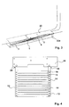
- zeigt die Trittstufe nach der ersten Variante im ausgeschwenkten Zustand in perspektivischer Darstellung;
- Fig. 2
- zeigt einen Ausschnitt aus Fig. 1 in vergrößerter Darstellung;
- Fig. 3
- zeigt die Trittstufe gemäß Fig. 1 im eingeschwenkten Zustand;
- Fig. 4
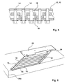
- zeigt in einer perspektivischen Darstellung den Aufbau einer Trittstufe gemäß der zweiten Variante;
- Fig. 5
- zeigt eine solche Trittstufe gemäß Fig. 3 in einer Seitenansicht im Schnitt;
- Fig. 6
- zeigt die Stufe gemäß der zweiten Variante in eingezogenem Zustand
- Fig. 7
- zeigt die Anbindung einer Schwinge an dem Boden des Fahrzeugs;
- Fig. 8
- zeigt den Ausschnitt mit der Anbindung des Spindelantriebes gemäß Fig. 1;
- Fig. 9
- zeigt einen Schnitt gemäß der Linie VIII - VIII aus Fig. 7.
- Fig. 1
- shows the tread after the first variant in the swung-out state in perspective view;
- Fig. 2
- shows a detail of Figure 1 in an enlarged view.
- Fig. 3
- shows the tread of Figure 1 in the pivoted state.
- Fig. 4
- shows a perspective view of the construction of a tread according to the second variant;
- Fig. 5
- shows such a step according to Figure 3 in a side view in section.
- Fig. 6
- shows the stage according to the second variant in the retracted state
- Fig. 7
- shows the connection of a rocker to the floor of the vehicle;
- Fig. 8
- shows the detail with the connection of the spindle drive of FIG. 1;
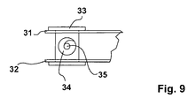
- Fig. 9
- shows a section along the line VIII - VIII of FIG. 7.
Bei der Ausbildung der ausschwingbaren Trittstufe gemäß den Figuren 1 und 2 zeigt die insgesamt mit 1 bezeichnete Trittstufe zwei Schwingen 2, 3, wobei die im Querschnitt U-förmig ausgebildeten Schwingen 2, 3 jeweils eine Vielzahl von hintereinander angeordneten Bolzen 4 aufweisen, wobei die mit 5 bezeichneten Trittglieder endseitig jeweils eine Öse 4a besitzen, die von den mit 4 bezeichneten Bolzen aufgenommen ist, wie sich dies aus der ausschnittsweisen Vergrößerung aus Fig. 2 ergibt. Hierbei ist erkennbar, dass die Trittglieder 5 diagonal zu den ihnen zugeordneten Bolzen 4 in den beiden Schwingen 2 und 3 verlaufen. Das heißt, die Anordnung des Trittgliedes an den Ösen 4a ist derart, dass das Trittglied an der einen Seite der einen Öse und an der anderen Seite der anderen Öse der jeweiligen Schwinge 2, 3 befestigt ist. Hierdurch wird erreicht, dass im zusammengeklappten Zustand gemäß Fig. 3 die einzelnen Trittglieder 5 unmittelbar aneinander anliegen. Das heißt, dass diese Art der Befestigung der Trittglieder an den Ösen zu einer platzsparenden Bauweise der Trittstufe in eingeklapptem Zustand führt.In the embodiment of the swing-out tread according to Figures 1 and 2, the total designated 1 tread two
In Bezug auf die zweite Variante wird nunmehr auf die Figuren 4 und 5 verwiesen. Gemäß Fig. 4 sind wiederum zwei Schwingen 12, 13 vorgesehen, die der Aufnahme von Bolzen 14 dienen. Auch hier sind die Schwingen im Querschnitt U-profilförmig ausgebildet. Die Bolzen werden hierbei durch die Schenkel der Schwingen gehalten, wie sich dies aus der Figur 4, aber auch aus der Figur 5 ergibt. Bei der Ausbildung der Trittstufe gemäß dieser zweiten Variante sind in den Trittgliedern wechselweise Stützglieder 16 vorgesehen, wobei sich die Trittglieder 15 auf den Stützgliedern 16 abstützen, wie sich dies unmittelbar in Anschauung der Fig. 5 ergibt.With respect to the second variant, reference is now made to Figures 4 and 5. According to FIG. 4, in turn, two
Fig. 6 zeigt die Trittstufe gemäß Fig. 4 in eingezogenem Zustand; hierbei ist erkennbar, dass aufgrund der Konstruktion die Tiefe der eingezogenen Stufe größer ist als bei der ersten Variante. Allerdings ist diese Stufe in sich stabiler.Fig. 6 shows the tread of Figure 4 in the retracted state. Here it can be seen that due to the construction, the depth of the retracted stage is greater than in the first variant. However, this level is inherently more stable.
Aus Fig. 7 ist erkennbar, wie die Schwingen einer jeden Variante am Boden des Fahrzeuges befestigt sind. Die mit 20 bezeichnete Platte, die mit dem Boden des Fahrzeuges verbunden wird, weist eine Gewindehülse 21 auf, die mit dem Boden des Fahrzeuges verschweißt ist. Um die Gewindehülse 21 herum befindet sich eine im Querschnitt doppel T-förmige Kunststoffhülse 22, wobei zwischen den Schenkeln der doppel T-förmigen Hülse 22 die insgesamt mit 2, 3 bzw. 12, 13 bezeichnete Schwinge lagert. Um bei Aufbringen eines Momentes auf die Schwinge, was dann der Fall ist, wenn z. B. eine Person auf der Trittstufe aufsteht, ein Einschneiden der im Querschnitt U-profilförmigen Schwinge in die Kunststoffhülse 22 zu vermeiden, ist die U-profilförmige Schwinge im Bereich der Kunststoffhülse 22 durch eine Hülse 23 geschlossen. Der mit 24 bezeichnete Bolzen ist nunmehr in die Hülse 21 eingedreht und in geeigneter Weise, z. B. durch Stifte 25, gegen Verdrehen gesichert.From Fig. 7 it can be seen how the wings of each variant are fixed to the floor of the vehicle. The designated 20 plate which is connected to the bottom of the vehicle, has a threaded
Für den elektromechanischen Antrieb zum Ein- und Ausschwenken der Trittstufe ist ein Spindelantrieb 30 vorgesehen, wie sich dies beispielhaft aus Fig. 1 in Verbindung mit Fig. 8 und Fig. 9 ergibt. Hierbei sind in den Schenkeln der Schwinge 2, 12 zwei übereinander angeordnete Augen oder Bohrungen 31 und 32 vorgesehen (Fig. 8), durch die ein Bolzen 33 schwenkbar aufnehmbar ist, wobei der Bolzen 33 in der Mitte eine Gewindebohrung 34 für die Spindel 35 aufweist. Der Spindelantrieb selbst zeigt die Nummer 36. Der Spindelantrieb 36 ist verschwenkbar ebenfalls an der Platte 20 für den Boden des Fahrzeuges gelagert, da er sich beim Ein- oder Ausziehen der Spindel verschwenkt.For the electromechanical drive for swinging in and out of the tread, a
Die Trittstufe ist, gegebenenfalls samt Antrieb, in einem Gehäuse 20a unter dem Fahrzeugboden 20 angeordnet, um die Stufe vor Verschmutzung und Witterungseinflüssen zu schützen.The tread is, optionally together with the drive, arranged in a
Claims (10)
gekennzeichnet durch,
zwei parallele Schwingen (2, 3; 12, 23), die an ihrem einen Ende drehbar an dem Fahrzeug (20) angeordnet sind, wobei die Schwingen (2, 3; 12, 13) durch mehrere hintereinander beabstandet zueinander angeordnete Trittglieder (5, 15) verbunden sind, wobei die Trittglieder (5, 15) jeweils drehbar durch die Schwingen (2, 3; 12, 13) aufnehmbar sind.Deployable step of a vehicle
characterized by
two parallel rockers (2,3,12,23) rotatably mounted at one end thereof on the vehicle (20), the rockers (2,3,12,13) being constituted by a plurality of step members (5; 15) are connected, wherein the tread members (5, 15) each rotatably by the wings (2, 3, 12, 13) are receivable.
dadurch gekennzeichnet,
dass die Trittglieder (5) im Querschnitt rechteckförmig ausgebildet sind, wobei die Trittglieder (5) vertikal ausgerichtet durch die Schwingen (2, 3) aufnehmbar sind.An extendable step according to claim 1,
characterized,
that the stepping members (5) are rectangular in cross-section, wherein the stepping members (5) vertically aligned by the rockers (2, 3) are receivable.
dadurch gekennzeichnet,
dass die Trittglieder (5) endseitig jeweils eine Öse (4a) aufweisen, wobei die Anordnung des Trittgliedes (5) an den Ösen (4a) derart ist, dass das Trittglied (5) an der einen Seite der einen Öse (4a) und an der anderen Seite der anderen Öse (4a) befestigt ist.An extendable step according to one of the preceding claims,
characterized,
in that the step members (5) each have an eyelet (4a) at the ends, the arrangement of the kick member (5) on the eyelets (4a) being such that the kick member (5) is attached to one side of the one eyelet (4a) and to the eyelet (4a) the other side of the other eyelet (4a) is attached.
dadurch gekennzeichnet,
dass die Trittglieder (15) im Querschnitt rechteckförmig ausgebildet sind, wobei die Trittglieder (12, 13) horizontal ausgerichtet durch die Schwingen (2, 3; 12, 13) aufnehmbar sind.An extendable step according to one of the preceding claims,
characterized,
in that the step members (15) are rectangular in cross-section, the step members (12, 13) being able to be received horizontally by the rockers (2, 3, 12, 13).
dadurch gekennzeichnet,
dass unter den Trittglieder (15) Stützglieder (16) vorgesehen sind, wobei die Stützglieder (16) im Abstand zwischen zwei Trittgliedern (15) ebenfalls drehbar durch die Schwingen (12, 13) aufnehmbar sind, wobei sich zwei Trittglieder (15) auf einem Stützglied (16) abstützen.Exposed tread according to claim 4
characterized,
in that support members (16) are provided under the step members (15), wherein the support members (16) are also rotatably receivable by the wings (12, 13) at a distance between two step members (15), with two step members (15) on one side Support support member (16).
dadurch gekennzeichnet,
dass die Schwingen (2, 3; 12, 13) in ihrer jeweiligen Endstellung arretierbar sind.An extendable step according to one of the preceding claims,
characterized,
in that the rockers (2, 3, 12, 13) can be locked in their respective end position.
dadurch gekennzeichnet,
dass die Schwingen (2, 3; 12, 13) im Querschnitt U-förmig ausgebildet sind.An extendable step according to one of the preceding claims,
characterized,
that the rockers (2, 3; 12, 13) in cross-section U-shaped.
dadurch gekennzeichnet,
dass zum Verschwenken der Schwingen (2, 3; 12, 13) ein Antrieb (30) vorgesehen ist.An extendable step according to one of the preceding claims,
characterized,
in that a drive (30) is provided for pivoting the rockers (2, 3, 12, 13).
dadurch gekennzeichnet,
dass der Antrieb (30) als Spindelantrieb ausgebildet ist.An extendable step according to claim 8,
characterized,
that the drive (30) is designed as a spindle drive.
dadurch gekennzeichnet,
dass die Trittstufe in einem Gehäuse (20a) des Fahrzeuges angeordnet ist, wobei das Gehäuse (20a) bei eingeklappter Trittstufe verschließbar ist.An extendable step according to one of the preceding claims,
characterized,
in that the tread is arranged in a housing (20a) of the vehicle, wherein the housing (20a) can be closed when the tread is folded in.
Applications Claiming Priority (1)
| Application Number | Priority Date | Filing Date | Title |
|---|---|---|---|
| DE102005062142A DE102005062142B3 (en) | 2005-12-22 | 2005-12-22 | Hinged step of vehicle has two parallel swinging arms connected by several step members spaced one behind other, wherein step members are each rotatably supported by swinging arms and each have an eye on ends |
Publications (1)
| Publication Number | Publication Date |
|---|---|
| EP1800640A1 true EP1800640A1 (en) | 2007-06-27 |
Family
ID=38268407
Family Applications (1)
| Application Number | Title | Priority Date | Filing Date |
|---|---|---|---|
| EP06024886A Withdrawn EP1800640A1 (en) | 2005-12-22 | 2006-12-01 | Pivoting footstep of a vehicle |
Country Status (2)
| Country | Link |
|---|---|
| EP (1) | EP1800640A1 (en) |
| DE (1) | DE102005062142B3 (en) |
Cited By (2)
| Publication number | Priority date | Publication date | Assignee | Title |
|---|---|---|---|---|
| EP2044916B2 (en) † | 2007-10-05 | 2015-12-09 | Gebr. Bode GmbH & Co. KG | Step plate device |
| EP4212391A1 (en) * | 2022-01-17 | 2023-07-19 | Volvo Truck Corporation | Collapsible step assembly for an industrial vehicle |
Families Citing this family (3)
| Publication number | Priority date | Publication date | Assignee | Title |
|---|---|---|---|---|
| CN101376355B (en) * | 2007-08-29 | 2012-04-18 | 卡特彼勒公司 | Machinery fitting ladder with height adjusting ladder |
| DE102015213650A1 (en) * | 2015-07-20 | 2017-01-26 | Bombardier Transportation Gmbh | Rail vehicle with bridge element for gap bridging between a door and a platform |
| DE102019213244A1 (en) * | 2019-09-02 | 2021-03-04 | Volkswagen Aktiengesellschaft | Extendable platform and motor vehicle with an extendable platform |
Citations (5)
| Publication number | Priority date | Publication date | Assignee | Title |
|---|---|---|---|---|
| US533209A (en) * | 1895-01-29 | Skid for- -railway-cars | ||
| US3516515A (en) * | 1968-10-15 | 1970-06-23 | Douglas Keith Clash | Foldable step structure for campers |
| DE8711088U1 (en) * | 1987-08-14 | 1987-10-08 | Binz Gmbh & Co, 7073 Lorch, De | |
| US5199731A (en) * | 1990-09-04 | 1993-04-06 | Martin Samuel K | Step assembly for vehicles |
| WO2006078195A1 (en) * | 2005-01-21 | 2006-07-27 | Volvo Lastvagnar Ab | Step for a vehicle |
Family Cites Families (1)
| Publication number | Priority date | Publication date | Assignee | Title |
|---|---|---|---|---|
| ES2107699T3 (en) * | 1994-02-25 | 1997-12-01 | Huebner Gummi & Kunststoff | ARTICULATED GANGWAY, IN DIAGONAL, MOBILE, AS PART OF AN INTERCOMMUNICATION BETWEEN TWO VEHICLES. |
-
2005
- 2005-12-22 DE DE102005062142A patent/DE102005062142B3/en not_active Expired - Fee Related
-
2006
- 2006-12-01 EP EP06024886A patent/EP1800640A1/en not_active Withdrawn
Patent Citations (5)
| Publication number | Priority date | Publication date | Assignee | Title |
|---|---|---|---|---|
| US533209A (en) * | 1895-01-29 | Skid for- -railway-cars | ||
| US3516515A (en) * | 1968-10-15 | 1970-06-23 | Douglas Keith Clash | Foldable step structure for campers |
| DE8711088U1 (en) * | 1987-08-14 | 1987-10-08 | Binz Gmbh & Co, 7073 Lorch, De | |
| US5199731A (en) * | 1990-09-04 | 1993-04-06 | Martin Samuel K | Step assembly for vehicles |
| WO2006078195A1 (en) * | 2005-01-21 | 2006-07-27 | Volvo Lastvagnar Ab | Step for a vehicle |
Cited By (2)
| Publication number | Priority date | Publication date | Assignee | Title |
|---|---|---|---|---|
| EP2044916B2 (en) † | 2007-10-05 | 2015-12-09 | Gebr. Bode GmbH & Co. KG | Step plate device |
| EP4212391A1 (en) * | 2022-01-17 | 2023-07-19 | Volvo Truck Corporation | Collapsible step assembly for an industrial vehicle |
Also Published As
| Publication number | Publication date |
|---|---|
| DE102005062142B3 (en) | 2007-08-02 |
Similar Documents
| Publication | Publication Date | Title |
|---|---|---|
| EP2815681B1 (en) | Adjusting mechanism for adjusting movable furniture parts | |
| EP2070499B1 (en) | Wheelchair lifting device | |
| EP2885587B1 (en) | Support structure for solar modules | |
| EP1836070B1 (en) | Vehicle seat | |
| EP3108864B1 (en) | Folding wheelchair | |
| DE102010052619A1 (en) | Vehicle seat with guided scissor arms | |
| DE10307149A1 (en) | Folding vehicle seat | |
| DE102006050662B3 (en) | Vehicle door hinge, has door and pillar bracket, which is framed by two spaced sections, where distance of spaced sections of door and pillar bracket is fixed by spacing element | |
| DE102016009038B4 (en) | Folding tip linkage and method for assembling a folding tip | |
| EP1800640A1 (en) | Pivoting footstep of a vehicle | |
| DE19920386C2 (en) | Storage for a foldable backrest | |
| EP0356761A1 (en) | Scissor lift device, especially for a working platform | |
| EP3656960A2 (en) | Vehicle hatch kinematics | |
| EP1323871B1 (en) | Outrigger device for working machines such as hydraulic excavators or the like | |
| DE102008004998A1 (en) | Height adjustable vehicle seat, has locking cam of joint arm and bolt of segment cooperate to determine adjusting position, where seat is transferred from adjusting position into another adjusting position in reversible manner | |
| DE102007024570B4 (en) | Hinge for a motor vehicle door | |
| EP2740872B1 (en) | Corner bearing for concealed assembly | |
| DE4342402A1 (en) | Drive and locking mechanism for a straight extendable roll bar | |
| DE102015008649A1 (en) | Vehicle seat and vehicle | |
| EP3748099B1 (en) | Awning | |
| DE102010018664B4 (en) | Device for connecting a vehicle seat to a turntable, turntable and vehicle seat | |
| DE102009006847B4 (en) | mobile shop | |
| DE102017215282A1 (en) | Vordachbaueinheit | |
| DE102009044220A1 (en) | Camera dolly has undercarriage and stroke camera with camera fastening device for attachment of camera and seat fastening device for attachment of cameraman seat | |
| DE19920672A1 (en) | Linear control device has telescopic tube, drive unit with drive wheels driven in synchronism in opposite directions in pairs that engage drive rod on diametrically opposite sides |
Legal Events
| Date | Code | Title | Description |
|---|---|---|---|
| PUAI | Public reference made under article 153(3) epc to a published international application that has entered the european phase |
Free format text: ORIGINAL CODE: 0009012 |
|
| AK | Designated contracting states |
Kind code of ref document: A1 Designated state(s): AT BE BG CH CY CZ DE DK EE ES FI FR GB GR HU IE IS IT LI LT LU LV MC NL PL PT RO SE SI SK TR |
|
| AX | Request for extension of the european patent |
Extension state: AL BA HR MK YU |
|
| AKX | Designation fees paid | ||
| STAA | Information on the status of an ep patent application or granted ep patent |
Free format text: STATUS: THE APPLICATION IS DEEMED TO BE WITHDRAWN |
|
| 18D | Application deemed to be withdrawn |
Effective date: 20071228 |
|
| REG | Reference to a national code |
Ref country code: DE Ref legal event code: 8566 |