EP1799400B1 - Verfahren zur herstellung einer nockenwelle - Google Patents
Verfahren zur herstellung einer nockenwelle Download PDFInfo
- Publication number
- EP1799400B1 EP1799400B1 EP05769704A EP05769704A EP1799400B1 EP 1799400 B1 EP1799400 B1 EP 1799400B1 EP 05769704 A EP05769704 A EP 05769704A EP 05769704 A EP05769704 A EP 05769704A EP 1799400 B1 EP1799400 B1 EP 1799400B1
- Authority
- EP
- European Patent Office
- Prior art keywords
- cams
- shaft
- camshaft
- cam
- finished
- Prior art date
- Legal status (The legal status is an assumption and is not a legal conclusion. Google has not performed a legal analysis and makes no representation as to the accuracy of the status listed.)
- Not-in-force
Links
- 238000004519 manufacturing process Methods 0.000 title claims abstract description 17
- 238000000034 method Methods 0.000 claims abstract description 16
- 230000002093 peripheral effect Effects 0.000 claims abstract description 3
- 238000003754 machining Methods 0.000 claims description 20
- 125000006850 spacer group Chemical group 0.000 claims description 9
- 238000005304 joining Methods 0.000 claims description 5
- 230000013011 mating Effects 0.000 claims 1
- 238000012545 processing Methods 0.000 description 20
- 238000012805 post-processing Methods 0.000 description 4
- 230000001419 dependent effect Effects 0.000 description 1
- 238000003780 insertion Methods 0.000 description 1
- 230000037431 insertion Effects 0.000 description 1
- 230000000149 penetrating effect Effects 0.000 description 1
- 239000013585 weight reducing agent Substances 0.000 description 1
Images


Classifications
-
- F—MECHANICAL ENGINEERING; LIGHTING; HEATING; WEAPONS; BLASTING
- F01—MACHINES OR ENGINES IN GENERAL; ENGINE PLANTS IN GENERAL; STEAM ENGINES
- F01L—CYCLICALLY OPERATING VALVES FOR MACHINES OR ENGINES
- F01L1/00—Valve-gear or valve arrangements, e.g. lift-valve gear
- F01L1/02—Valve drive
- F01L1/04—Valve drive by means of cams, camshafts, cam discs, eccentrics or the like
- F01L1/047—Camshafts
-
- B—PERFORMING OPERATIONS; TRANSPORTING
- B23—MACHINE TOOLS; METAL-WORKING NOT OTHERWISE PROVIDED FOR
- B23P—METAL-WORKING NOT OTHERWISE PROVIDED FOR; COMBINED OPERATIONS; UNIVERSAL MACHINE TOOLS
- B23P15/00—Making specific metal objects by operations not covered by a single other subclass or a group in this subclass
-
- F—MECHANICAL ENGINEERING; LIGHTING; HEATING; WEAPONS; BLASTING
- F01—MACHINES OR ENGINES IN GENERAL; ENGINE PLANTS IN GENERAL; STEAM ENGINES
- F01L—CYCLICALLY OPERATING VALVES FOR MACHINES OR ENGINES
- F01L1/00—Valve-gear or valve arrangements, e.g. lift-valve gear
- F01L1/34—Valve-gear or valve arrangements, e.g. lift-valve gear characterised by the provision of means for changing the timing of the valves without changing the duration of opening and without affecting the magnitude of the valve lift
- F01L1/344—Valve-gear or valve arrangements, e.g. lift-valve gear characterised by the provision of means for changing the timing of the valves without changing the duration of opening and without affecting the magnitude of the valve lift changing the angular relationship between crankshaft and camshaft, e.g. using helicoidal gear
- F01L1/34413—Valve-gear or valve arrangements, e.g. lift-valve gear characterised by the provision of means for changing the timing of the valves without changing the duration of opening and without affecting the magnitude of the valve lift changing the angular relationship between crankshaft and camshaft, e.g. using helicoidal gear using composite camshafts, e.g. with cams being able to move relative to the camshaft
-
- F—MECHANICAL ENGINEERING; LIGHTING; HEATING; WEAPONS; BLASTING
- F16—ENGINEERING ELEMENTS AND UNITS; GENERAL MEASURES FOR PRODUCING AND MAINTAINING EFFECTIVE FUNCTIONING OF MACHINES OR INSTALLATIONS; THERMAL INSULATION IN GENERAL
- F16H—GEARING
- F16H53/00—Cams ; Non-rotary cams; or cam-followers, e.g. rollers for gearing mechanisms
- F16H53/02—Single-track cams for single-revolution cycles; Camshafts with such cams
- F16H53/025—Single-track cams for single-revolution cycles; Camshafts with such cams characterised by their construction, e.g. assembling or manufacturing features
-
- B—PERFORMING OPERATIONS; TRANSPORTING
- B23—MACHINE TOOLS; METAL-WORKING NOT OTHERWISE PROVIDED FOR
- B23P—METAL-WORKING NOT OTHERWISE PROVIDED FOR; COMBINED OPERATIONS; UNIVERSAL MACHINE TOOLS
- B23P2700/00—Indexing scheme relating to the articles being treated, e.g. manufactured, repaired, assembled, connected or other operations covered in the subgroups
- B23P2700/02—Camshafts
-
- F—MECHANICAL ENGINEERING; LIGHTING; HEATING; WEAPONS; BLASTING
- F01—MACHINES OR ENGINES IN GENERAL; ENGINE PLANTS IN GENERAL; STEAM ENGINES
- F01L—CYCLICALLY OPERATING VALVES FOR MACHINES OR ENGINES
- F01L1/00—Valve-gear or valve arrangements, e.g. lift-valve gear
- F01L1/02—Valve drive
- F01L1/04—Valve drive by means of cams, camshafts, cam discs, eccentrics or the like
- F01L1/047—Camshafts
- F01L2001/0471—Assembled camshafts
- F01L2001/0473—Composite camshafts, e.g. with cams or cam sleeve being able to move relative to the inner camshaft or a cam adjusting rod
-
- Y—GENERAL TAGGING OF NEW TECHNOLOGICAL DEVELOPMENTS; GENERAL TAGGING OF CROSS-SECTIONAL TECHNOLOGIES SPANNING OVER SEVERAL SECTIONS OF THE IPC; TECHNICAL SUBJECTS COVERED BY FORMER USPC CROSS-REFERENCE ART COLLECTIONS [XRACs] AND DIGESTS
- Y10—TECHNICAL SUBJECTS COVERED BY FORMER USPC
- Y10T—TECHNICAL SUBJECTS COVERED BY FORMER US CLASSIFICATION
- Y10T29/00—Metal working
- Y10T29/49—Method of mechanical manufacture
- Y10T29/49229—Prime mover or fluid pump making
- Y10T29/49286—Crankshaft making
-
- Y—GENERAL TAGGING OF NEW TECHNOLOGICAL DEVELOPMENTS; GENERAL TAGGING OF CROSS-SECTIONAL TECHNOLOGIES SPANNING OVER SEVERAL SECTIONS OF THE IPC; TECHNICAL SUBJECTS COVERED BY FORMER USPC CROSS-REFERENCE ART COLLECTIONS [XRACs] AND DIGESTS
- Y10—TECHNICAL SUBJECTS COVERED BY FORMER USPC
- Y10T—TECHNICAL SUBJECTS COVERED BY FORMER US CLASSIFICATION
- Y10T29/00—Metal working
- Y10T29/49—Method of mechanical manufacture
- Y10T29/49229—Prime mover or fluid pump making
- Y10T29/49293—Camshaft making
-
- Y—GENERAL TAGGING OF NEW TECHNOLOGICAL DEVELOPMENTS; GENERAL TAGGING OF CROSS-SECTIONAL TECHNOLOGIES SPANNING OVER SEVERAL SECTIONS OF THE IPC; TECHNICAL SUBJECTS COVERED BY FORMER USPC CROSS-REFERENCE ART COLLECTIONS [XRACs] AND DIGESTS
- Y10—TECHNICAL SUBJECTS COVERED BY FORMER USPC
- Y10T—TECHNICAL SUBJECTS COVERED BY FORMER US CLASSIFICATION
- Y10T29/00—Metal working
- Y10T29/49—Method of mechanical manufacture
- Y10T29/49826—Assembling or joining
- Y10T29/4984—Retaining clearance for motion between assembled parts
-
- Y—GENERAL TAGGING OF NEW TECHNOLOGICAL DEVELOPMENTS; GENERAL TAGGING OF CROSS-SECTIONAL TECHNOLOGIES SPANNING OVER SEVERAL SECTIONS OF THE IPC; TECHNICAL SUBJECTS COVERED BY FORMER USPC CROSS-REFERENCE ART COLLECTIONS [XRACs] AND DIGESTS
- Y10—TECHNICAL SUBJECTS COVERED BY FORMER USPC
- Y10T—TECHNICAL SUBJECTS COVERED BY FORMER US CLASSIFICATION
- Y10T29/00—Metal working
- Y10T29/49—Method of mechanical manufacture
- Y10T29/49826—Assembling or joining
- Y10T29/49863—Assembling or joining with prestressing of part
- Y10T29/49865—Assembling or joining with prestressing of part by temperature differential [e.g., shrink fit]
-
- Y—GENERAL TAGGING OF NEW TECHNOLOGICAL DEVELOPMENTS; GENERAL TAGGING OF CROSS-SECTIONAL TECHNOLOGIES SPANNING OVER SEVERAL SECTIONS OF THE IPC; TECHNICAL SUBJECTS COVERED BY FORMER USPC CROSS-REFERENCE ART COLLECTIONS [XRACs] AND DIGESTS
- Y10—TECHNICAL SUBJECTS COVERED BY FORMER USPC
- Y10T—TECHNICAL SUBJECTS COVERED BY FORMER US CLASSIFICATION
- Y10T29/00—Metal working
- Y10T29/49—Method of mechanical manufacture
- Y10T29/49826—Assembling or joining
- Y10T29/49895—Associating parts by use of aligning means [e.g., use of a drift pin or a "fixture"]
- Y10T29/49899—Associating parts by use of aligning means [e.g., use of a drift pin or a "fixture"] by multiple cooperating aligning means
-
- Y—GENERAL TAGGING OF NEW TECHNOLOGICAL DEVELOPMENTS; GENERAL TAGGING OF CROSS-SECTIONAL TECHNOLOGIES SPANNING OVER SEVERAL SECTIONS OF THE IPC; TECHNICAL SUBJECTS COVERED BY FORMER USPC CROSS-REFERENCE ART COLLECTIONS [XRACs] AND DIGESTS
- Y10—TECHNICAL SUBJECTS COVERED BY FORMER USPC
- Y10T—TECHNICAL SUBJECTS COVERED BY FORMER US CLASSIFICATION
- Y10T29/00—Metal working
- Y10T29/49—Method of mechanical manufacture
- Y10T29/49826—Assembling or joining
- Y10T29/49904—Assembling a subassembly, then assembling with a second subassembly
-
- Y—GENERAL TAGGING OF NEW TECHNOLOGICAL DEVELOPMENTS; GENERAL TAGGING OF CROSS-SECTIONAL TECHNOLOGIES SPANNING OVER SEVERAL SECTIONS OF THE IPC; TECHNICAL SUBJECTS COVERED BY FORMER USPC CROSS-REFERENCE ART COLLECTIONS [XRACs] AND DIGESTS
- Y10—TECHNICAL SUBJECTS COVERED BY FORMER USPC
- Y10T—TECHNICAL SUBJECTS COVERED BY FORMER US CLASSIFICATION
- Y10T29/00—Metal working
- Y10T29/49—Method of mechanical manufacture
- Y10T29/49995—Shaping one-piece blank by removing material
-
- Y—GENERAL TAGGING OF NEW TECHNOLOGICAL DEVELOPMENTS; GENERAL TAGGING OF CROSS-SECTIONAL TECHNOLOGIES SPANNING OVER SEVERAL SECTIONS OF THE IPC; TECHNICAL SUBJECTS COVERED BY FORMER USPC CROSS-REFERENCE ART COLLECTIONS [XRACs] AND DIGESTS
- Y10—TECHNICAL SUBJECTS COVERED BY FORMER USPC
- Y10T—TECHNICAL SUBJECTS COVERED BY FORMER US CLASSIFICATION
- Y10T74/00—Machine element or mechanism
- Y10T74/21—Elements
- Y10T74/2101—Cams
Definitions
- the invention relates to a method for producing a camshaft according to the preamble of patent claim 1.
- the cams can be ground as a module.
- the ground cams are individually pushed onto a shaft to produce a camshaft.
- the invention is concerned with the problem of being able to do without a post-processing of the contours of the individual cams on the finished camshaft in a generic manufacturing process of camshafts.
- the invention is based on the general idea to combine the individual cams before placing on a shaft and connecting with this shaft to a processing module in those mutual assignment, in which the cams are to lie on the finished camshaft. Within this processing module the finishing of the cams is carried out. Thus finished the cams are joined within the machining module on the shaft of the camshaft. This ensures that the desired mutual assignment is given, that is, that a post-processing is unnecessary.
- screws for axial clamping of the individual elements can be used with each other or serve after the insertion of dowel pins as a clamping means during machining and joining.
- the screws can have the form of countersunk screws.
- clamping means any other clamping means, such as well-known clamping means during grinding.
- a camshaft with cams which can be rotated variably relative to one another can be produced particularly advantageously.
- an inner shaft is mounted concentrically in an outer shaft, wherein the two shafts are rotatable relative to each other.
- the first cam and the inner shaft second cam are each firmly connected to the outer shaft.
- the second cams are fixedly connected to the inner shaft, for example through these cams each radially penetrating, the outer shaft by a recess provided there crosses, fixed in the inner shaft connecting elements, such as dowel pins.
- Such second cams are rotatably mounted on the outer shaft. Because in such a camshaft, a subsequent mechanical processing of the - partially mutually adjustable - already finished cams is difficult, the method of the invention proves to be particularly advantageous for this purpose.
- a second cam which must be provided for an adjustable camshaft with a radial bore for receiving a fastener, such as a dowel pin to thereby within the finished camshaft can be positioned and rotated, so this hole can be made while the relevant second cam is in the processing module. As a result, a precisely fitting angular position of the respective second cam is ensured within the finished camshaft.
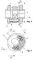
- first cams 1, 2 which lie respectively at the axially outer ends.
- second cam 4 is axially spaced apart in the middle of the machining module.
- the total of three first and second cams 1, 2, 4 are connected to each other via two circumferentially approximately opposite screws 5.
- the two screws 5 are preferably designed as countersunk screws.
- the cams 1, 2, 4, which are firmly connected to one another in the processing module, can be finished in this state, in particular with respect to their outer contour of the cams as well as their inner diameter.
- the inner diameter for all cams 1, 2, 4 are chosen equal to simplify the processing.
- cams 1, 2, 4 for a camshaft with respect to their angular position variable against each other adjustable cam.
- the to the cams 1, 2, 4 associated shaft is composed of an inner shaft 11 and one concentrically enclosing them Outer shaft 12 ( Fig. 6 ).
- the two shafts 11, 12 are rotatable relative to each other. The relative rotation is usually carried out in that the inner shaft 11 is rotated in the outer shaft 12.
- the two in the processing module axially outer first cam 1, 2 are intended for a tight fit on the outer shaft 12.
- the second cam 4 lying between these two cams 1, 2 is designed for a firm connection to the inner shaft 11.
- a fastening element which may be a dowel pin 13.
- This dowel pin 13 is fixed on the one hand in the fitting bore 7 of the second cam 4 and on the other hand in a bore of the inner shaft 11 and passed through a slot-like recess 14 in the outer shaft 12.
- the fitting bore 7 of the second cam 4 is generated while this second cam 4 is in the closed machining module.
- the cams 1, 2, 4 are finished before the processing operations that are still carried out on them within the processing module, before.
- the machining module After placing the machining module on the outer shaft 12 of the reproduced in the embodiment as an adjustable camshaft camshaft ( Fig. 6 ), that is, after completion and existence of an example shrinkage connection between the first cams 1, 2 with the outer shaft 12, the machining module is opened, and the screws 5 and the circumferentially open spacers 3 are removed.
- the remaining in the cams 1, 2, 4 holes 10 inevitably lead to the advantage of a weight reduction in these holes 10 having cams.
- threads 8 can advantageously be introduced into optionally existing spacers 3 (FIG. Fig. 3 to 5 ).
- at least two screws 5 each have to be inserted axially opposite to their head and threaded position in order to ensure a play-free and detachable assignment to the cams 1, 2, 4 ( Fig. 3 to 5 ).
- the spacers 3 must have at least four holes 10, of which two are each formed as a through hole and two as a thread 8.
- the outer shaft 12 In order that an adjustable, second cam 4 in the processing module can be machined to the same inner diameter as the remaining first cams 1, 2, the outer shaft 12 must have a recess 9 with a reduced diameter in that region in which the second cam 4 comes to rest Own diameter ( Fig. 6 ). Reduced is the outer diameter of the outer shaft 12 to such an extent that the second cam 4 can play in this area on the outer shaft 12 rotatably support.
- the inner surfaces and the concentric outer surfaces or cam surfaces are to be understood. Particularly important with respect to machining within the machining module are the cam contours.
Landscapes
- Engineering & Computer Science (AREA)
- Mechanical Engineering (AREA)
- General Engineering & Computer Science (AREA)
- Valve-Gear Or Valve Arrangements (AREA)
- Valve Device For Special Equipments (AREA)
- Grinding And Polishing Of Tertiary Curved Surfaces And Surfaces With Complex Shapes (AREA)
Applications Claiming Priority (2)
| Application Number | Priority Date | Filing Date | Title |
|---|---|---|---|
| DE102004039302A DE102004039302A1 (de) | 2004-08-13 | 2004-08-13 | Verfahren zur Herstellung einer Nockenwelle |
| PCT/DE2005/001250 WO2006015570A1 (de) | 2004-08-13 | 2005-07-15 | Verfahren zur herstellung einer nockenwelle |
Publications (2)
| Publication Number | Publication Date |
|---|---|
| EP1799400A1 EP1799400A1 (de) | 2007-06-27 |
| EP1799400B1 true EP1799400B1 (de) | 2008-09-03 |
Family
ID=35355969
Family Applications (1)
| Application Number | Title | Priority Date | Filing Date |
|---|---|---|---|
| EP05769704A Not-in-force EP1799400B1 (de) | 2004-08-13 | 2005-07-15 | Verfahren zur herstellung einer nockenwelle |
Country Status (6)
| Country | Link |
|---|---|
| US (1) | US7845075B2 (ja) |
| EP (1) | EP1799400B1 (ja) |
| JP (1) | JP4758994B2 (ja) |
| CN (1) | CN100526010C (ja) |
| DE (2) | DE102004039302A1 (ja) |
| WO (1) | WO2006015570A1 (ja) |
Families Citing this family (13)
| Publication number | Priority date | Publication date | Assignee | Title |
|---|---|---|---|---|
| DE102006044010A1 (de) * | 2006-05-13 | 2007-11-15 | Mahle International Gmbh | Verfahren zum Schleifen von Nockenprofilen |
| US8235019B2 (en) * | 2009-11-11 | 2012-08-07 | GM Global Technology Operations LLC | Engine having concentric camshaft with differential valve lift |
| JP4883330B2 (ja) * | 2009-11-25 | 2012-02-22 | 三菱自動車工業株式会社 | 内燃機関の可変動弁装置 |
| US8550051B2 (en) * | 2009-12-16 | 2013-10-08 | GM Global Technology Operations LLC | Engine combustion chamber features for camshaft with differential valve lift |
| US8397686B2 (en) * | 2009-12-16 | 2013-03-19 | GM Global Technology Operations LLC | Engine intake port arrangement for camshaft with differential valve lift |
| CN101871376A (zh) * | 2010-06-01 | 2010-10-27 | 奇瑞汽车股份有限公司 | 一种汽车发动机凸轮轴及其加工方法 |
| DE102010032746A1 (de) * | 2010-07-29 | 2012-02-02 | Neumayer Tekfor Holding Gmbh | Verfahren zur Fertigung einer Nockenwelle |
| DE102011051480B4 (de) * | 2011-06-30 | 2014-11-20 | Thyssenkrupp Presta Teccenter Ag | Nockenwelle mit axial verschiebbarem Nockenpaket |
| KR101101862B1 (ko) * | 2011-09-28 | 2012-01-05 | 주식회사 미보 | 캠 샤프트의 조립 장치 |
| DE102014109827B4 (de) * | 2014-07-14 | 2017-01-19 | Thyssenkrupp Presta Teccenter Ag | Verfahren zur Schleifbearbeitung von Nockenelementen einer verstellbaren Nockenwelle |
| DE102014018784A1 (de) | 2014-12-19 | 2016-06-23 | Thyssenkrupp Presta Teccenter Ag | Verfahren zur Erzeugung eines Nockenprofils eines Nockenpaketes einer Nockenwelle und Nockenwelle |
| CN106695290B (zh) * | 2016-12-30 | 2019-02-22 | 湖南先步信息股份有限公司 | 智能标准装配系统 |
| CN109693161A (zh) * | 2018-12-07 | 2019-04-30 | 中国航空工业集团公司济南特种结构研究所 | 一种复合材料雷达罩型面快速复制修磨装置及方法 |
Family Cites Families (12)
| Publication number | Priority date | Publication date | Assignee | Title |
|---|---|---|---|---|
| DE3301749A1 (de) * | 1983-01-20 | 1984-08-09 | Mahle Gmbh, 7000 Stuttgart | Nockenwelle fuer verbrennungsmotoren |
| GB8409771D0 (en) * | 1984-04-14 | 1984-05-23 | Ae Plc | Manufacture of camshafts |
| DE3626683A1 (de) * | 1986-08-07 | 1988-02-18 | Uni Cardan Ag | Verfahren und vorrichtung zum fertigstellen von nockenscheiben |
| DE3807817C1 (ja) | 1988-03-10 | 1989-03-09 | Balcke-Duerr Ag, 4030 Ratingen, De | |
| DE3943426C1 (ja) * | 1989-12-22 | 1991-04-11 | Gkn Automotive Ag, 5200 Siegburg, De | |
| DE3943427C1 (ja) * | 1989-12-22 | 1991-04-04 | Gkn Automotive Ag, 5200 Siegburg, De | |
| EP0494285B1 (de) | 1990-07-27 | 1994-10-26 | Karl Mettler-Friedli | Verbindung eines auf fertigmass gefertigten zylinderkörpers |
| US5201246A (en) * | 1992-07-20 | 1993-04-13 | General Motors Corporation | Lightweight composite camshaft |
| JPH07102914A (ja) * | 1993-03-03 | 1995-04-18 | Peter Amborn | 相互に位置決めされる軸要素を備えたカム軸構体およびその製造方法 |
| DE4306621C2 (de) * | 1993-03-03 | 1996-01-25 | Peter Dr Ing Amborn | Verfahren zur Herstellung einer Nockenwellenanordnung mit ineinanderliegenden Wellenelementen |
| DE19757504B4 (de) * | 1997-12-23 | 2005-03-31 | Daimlerchrysler Ag | Gebaute Nockenwelle für eine Brennkraftmaschine |
| GB2375583B (en) * | 2001-05-15 | 2004-09-01 | Mechadyne Internat Plc | Variable camshaft assembly |
-
2004
- 2004-08-13 DE DE102004039302A patent/DE102004039302A1/de not_active Withdrawn
-
2005
- 2005-07-15 US US10/574,629 patent/US7845075B2/en not_active Expired - Fee Related
- 2005-07-15 WO PCT/DE2005/001250 patent/WO2006015570A1/de active IP Right Grant
- 2005-07-15 EP EP05769704A patent/EP1799400B1/de not_active Not-in-force
- 2005-07-15 CN CN200580000935.9A patent/CN100526010C/zh not_active Expired - Fee Related
- 2005-07-15 DE DE502005005281T patent/DE502005005281D1/de active Active
- 2005-07-15 JP JP2007525157A patent/JP4758994B2/ja not_active Expired - Fee Related
Also Published As
| Publication number | Publication date |
|---|---|
| CN100526010C (zh) | 2009-08-12 |
| US20070039172A1 (en) | 2007-02-22 |
| US7845075B2 (en) | 2010-12-07 |
| CN1842398A (zh) | 2006-10-04 |
| JP2008509013A (ja) | 2008-03-27 |
| EP1799400A1 (de) | 2007-06-27 |
| WO2006015570A1 (de) | 2006-02-16 |
| JP4758994B2 (ja) | 2011-08-31 |
| DE102004039302A1 (de) | 2006-02-23 |
| DE502005005281D1 (de) | 2008-10-16 |
Similar Documents
| Publication | Publication Date | Title |
|---|---|---|
| EP1799400B1 (de) | Verfahren zur herstellung einer nockenwelle | |
| DE102005062208B4 (de) | Nockenwelle | |
| EP1989021A1 (de) | Verfahren und vorrichtung zur fertigbearbeitung von gebauten nocken- und exzenterwellen | |
| EP1351796B1 (de) | Verfahren zur herstellung einer gebauten welle | |
| EP2934814A2 (de) | Verfahren zum zusammenbau einer nockenwelle | |
| EP2516106A1 (de) | Montagevorrichtung und verfahren zur montage eines wellen-hauben-moduls | |
| DE102013015677A1 (de) | Verfahren zur Herstellung eines Sinterteils mit hochgenauer radialer Präzision sowie Teilesatz mit Sinterfügeteilen | |
| DE102005039751A1 (de) | Nockenwelle | |
| EP2745980B1 (de) | Verfahren zum thermischen Fügen von unrunden Funktionsbauteilen auf einer Welle | |
| EP3176390B1 (de) | Verstellbare nockenwelle | |
| DE102011053651B4 (de) | Spannvorrichtung und Spannverfahren zum kraftschlüssigen Festspannen von einem oder mehreren Werkstücken mit einer innenverzahnten Aufnahmebohrung | |
| DE202011051311U1 (de) | Spannvorrichtung zum kraftschlüssigen Festspannen von einem oder mehreren Werkstücken mit einer innenverzahnten Aufnahmebohrung | |
| EP3567708B1 (de) | Sekundärteil für einen eisenlosen linearmotor | |
| EP2759362A1 (de) | Spanneinrichtung | |
| WO2013067991A1 (de) | Verfahren zur fertigung einer nockenwelle und entsprechende nockenwelle | |
| DE19529901A1 (de) | Knochenschraube | |
| WO2019137683A1 (de) | Verfahren zum herstellen einer gewinderolle und gewinderolle | |
| WO2018224237A1 (de) | Innenspannmittel mit gesichertem spannsegmentring | |
| DE102013211161A1 (de) | Verfahren zur Montage einer verstellbaren Nockenwelle | |
| DE102010046044A1 (de) | Reibahle | |
| DE3700693A1 (de) | Kugelgewindetrieb | |
| DE102015215492A1 (de) | Verfahren zum Herstellen einer variablen Turbinengeometrie eines Abgasturboladers | |
| DE102013210905A1 (de) | Schraubverbindung von mindestens zwei aneinander anliegenden Bauteilen | |
| DE1525376A1 (de) | Spannringsatz | |
| DE60014467T2 (de) | Methode und Vorrichtung zum Bearbeiten von Komponenten |
Legal Events
| Date | Code | Title | Description |
|---|---|---|---|
| PUAI | Public reference made under article 153(3) epc to a published international application that has entered the european phase |
Free format text: ORIGINAL CODE: 0009012 |
|
| 17P | Request for examination filed |
Effective date: 20070105 |
|
| AK | Designated contracting states |
Kind code of ref document: A1 Designated state(s): DE FR GB |
|
| RIN1 | Information on inventor provided before grant (corrected) |
Inventor name: HENTSCHEL, TILO Inventor name: LECHNER, MARTIN Inventor name: HOFFMANN, HERMANN Inventor name: FRITZ, OLIVER |
|
| DAX | Request for extension of the european patent (deleted) | ||
| RBV | Designated contracting states (corrected) |
Designated state(s): DE FR GB |
|
| RIC1 | Information provided on ipc code assigned before grant |
Ipc: B23P 15/00 20060101AFI20080229BHEP Ipc: F01L 1/047 20060101ALI20080229BHEP Ipc: F01L 1/344 20060101ALI20080229BHEP Ipc: F16H 53/02 20060101ALI20080229BHEP |
|
| GRAP | Despatch of communication of intention to grant a patent |
Free format text: ORIGINAL CODE: EPIDOSNIGR1 |
|
| RBV | Designated contracting states (corrected) |
Designated state(s): DE FR GB |
|
| GRAS | Grant fee paid |
Free format text: ORIGINAL CODE: EPIDOSNIGR3 |
|
| GRAA | (expected) grant |
Free format text: ORIGINAL CODE: 0009210 |
|
| AK | Designated contracting states |
Kind code of ref document: B1 Designated state(s): DE FR GB |
|
| REG | Reference to a national code |
Ref country code: GB Ref legal event code: FG4D Free format text: NOT ENGLISH |
|
| REF | Corresponds to: |
Ref document number: 502005005281 Country of ref document: DE Date of ref document: 20081016 Kind code of ref document: P |
|
| PLBE | No opposition filed within time limit |
Free format text: ORIGINAL CODE: 0009261 |
|
| STAA | Information on the status of an ep patent application or granted ep patent |
Free format text: STATUS: NO OPPOSITION FILED WITHIN TIME LIMIT |
|
| 26N | No opposition filed |
Effective date: 20090604 |
|
| PGFP | Annual fee paid to national office [announced via postgrant information from national office to epo] |
Ref country code: FR Payment date: 20140729 Year of fee payment: 10 Ref country code: GB Payment date: 20140729 Year of fee payment: 10 |
|
| PGFP | Annual fee paid to national office [announced via postgrant information from national office to epo] |
Ref country code: DE Payment date: 20140930 Year of fee payment: 10 |
|
| REG | Reference to a national code |
Ref country code: DE Ref legal event code: R119 Ref document number: 502005005281 Country of ref document: DE |
|
| GBPC | Gb: european patent ceased through non-payment of renewal fee |
Effective date: 20150715 |
|
| PG25 | Lapsed in a contracting state [announced via postgrant information from national office to epo] |
Ref country code: DE Free format text: LAPSE BECAUSE OF NON-PAYMENT OF DUE FEES Effective date: 20160202 Ref country code: GB Free format text: LAPSE BECAUSE OF NON-PAYMENT OF DUE FEES Effective date: 20150715 |
|
| REG | Reference to a national code |
Ref country code: FR Ref legal event code: ST Effective date: 20160331 |
|
| PG25 | Lapsed in a contracting state [announced via postgrant information from national office to epo] |
Ref country code: FR Free format text: LAPSE BECAUSE OF NON-PAYMENT OF DUE FEES Effective date: 20150731 |