EP3567708B1 - Sekundärteil für einen eisenlosen linearmotor - Google Patents
Sekundärteil für einen eisenlosen linearmotor Download PDFInfo
- Publication number
- EP3567708B1 EP3567708B1 EP18171383.5A EP18171383A EP3567708B1 EP 3567708 B1 EP3567708 B1 EP 3567708B1 EP 18171383 A EP18171383 A EP 18171383A EP 3567708 B1 EP3567708 B1 EP 3567708B1
- Authority
- EP
- European Patent Office
- Prior art keywords
- screw
- secondary part
- yoke plate
- spacer element
- linear motor
- Prior art date
- Legal status (The legal status is an assumption and is not a legal conclusion. Google has not performed a legal analysis and makes no representation as to the accuracy of the status listed.)
- Active
Links
- 125000006850 spacer group Chemical group 0.000 claims description 23
- 238000004519 manufacturing process Methods 0.000 description 3
- 230000005415 magnetization Effects 0.000 description 2
- XEEYBQQBJWHFJM-UHFFFAOYSA-N Iron Chemical group [Fe] XEEYBQQBJWHFJM-UHFFFAOYSA-N 0.000 description 1
- 238000010276 construction Methods 0.000 description 1
- 238000005516 engineering process Methods 0.000 description 1
- 238000000034 method Methods 0.000 description 1
- 239000002966 varnish Substances 0.000 description 1
Images

Classifications
-
- H—ELECTRICITY
- H02—GENERATION; CONVERSION OR DISTRIBUTION OF ELECTRIC POWER
- H02K—DYNAMO-ELECTRIC MACHINES
- H02K15/00—Methods or apparatus specially adapted for manufacturing, assembling, maintaining or repairing of dynamo-electric machines
- H02K15/02—Methods or apparatus specially adapted for manufacturing, assembling, maintaining or repairing of dynamo-electric machines of stator or rotor bodies
- H02K15/03—Methods or apparatus specially adapted for manufacturing, assembling, maintaining or repairing of dynamo-electric machines of stator or rotor bodies having permanent magnets
-
- F—MECHANICAL ENGINEERING; LIGHTING; HEATING; WEAPONS; BLASTING
- F16—ENGINEERING ELEMENTS AND UNITS; GENERAL MEASURES FOR PRODUCING AND MAINTAINING EFFECTIVE FUNCTIONING OF MACHINES OR INSTALLATIONS; THERMAL INSULATION IN GENERAL
- F16B—DEVICES FOR FASTENING OR SECURING CONSTRUCTIONAL ELEMENTS OR MACHINE PARTS TOGETHER, e.g. NAILS, BOLTS, CIRCLIPS, CLAMPS, CLIPS OR WEDGES; JOINTS OR JOINTING
- F16B37/00—Nuts or like thread-engaging members
- F16B37/12—Nuts or like thread-engaging members with thread-engaging surfaces formed by inserted coil-springs, discs, or the like; Independent pieces of wound wire used as nuts; Threaded inserts for holes
- F16B37/122—Threaded inserts, e.g. "rampa bolts"
-
- F—MECHANICAL ENGINEERING; LIGHTING; HEATING; WEAPONS; BLASTING
- F16—ENGINEERING ELEMENTS AND UNITS; GENERAL MEASURES FOR PRODUCING AND MAINTAINING EFFECTIVE FUNCTIONING OF MACHINES OR INSTALLATIONS; THERMAL INSULATION IN GENERAL
- F16B—DEVICES FOR FASTENING OR SECURING CONSTRUCTIONAL ELEMENTS OR MACHINE PARTS TOGETHER, e.g. NAILS, BOLTS, CIRCLIPS, CLAMPS, CLIPS OR WEDGES; JOINTS OR JOINTING
- F16B5/00—Joining sheets or plates, e.g. panels, to one another or to strips or bars parallel to them
- F16B5/02—Joining sheets or plates, e.g. panels, to one another or to strips or bars parallel to them by means of fastening members using screw-thread
-
- H—ELECTRICITY
- H02—GENERATION; CONVERSION OR DISTRIBUTION OF ELECTRIC POWER
- H02K—DYNAMO-ELECTRIC MACHINES
- H02K3/00—Details of windings
- H02K3/46—Fastening of windings on the stator or rotor structure
- H02K3/47—Air-gap windings, i.e. iron-free windings
-
- H—ELECTRICITY
- H02—GENERATION; CONVERSION OR DISTRIBUTION OF ELECTRIC POWER
- H02K—DYNAMO-ELECTRIC MACHINES
- H02K41/00—Propulsion systems in which a rigid body is moved along a path due to dynamo-electric interaction between the body and a magnetic field travelling along the path
- H02K41/02—Linear motors; Sectional motors
- H02K41/03—Synchronous motors; Motors moving step by step; Reluctance motors
- H02K41/031—Synchronous motors; Motors moving step by step; Reluctance motors of the permanent magnet type
-
- H—ELECTRICITY
- H02—GENERATION; CONVERSION OR DISTRIBUTION OF ELECTRIC POWER
- H02K—DYNAMO-ELECTRIC MACHINES
- H02K1/00—Details of the magnetic circuit
- H02K1/06—Details of the magnetic circuit characterised by the shape, form or construction
- H02K1/12—Stationary parts of the magnetic circuit
- H02K1/17—Stator cores with permanent magnets
-
- H—ELECTRICITY
- H02—GENERATION; CONVERSION OR DISTRIBUTION OF ELECTRIC POWER
- H02K—DYNAMO-ELECTRIC MACHINES
- H02K1/00—Details of the magnetic circuit
- H02K1/06—Details of the magnetic circuit characterised by the shape, form or construction
- H02K1/34—Reciprocating, oscillating or vibrating parts of the magnetic circuit
Definitions
- This document relates to embodiments of a secondary part for a linear motor, in particular embodiments of a secondary part for an ironless linear motor, and embodiments of an ironless linear motor.
- ironless linear motors are from WO 2017/163978 A1 , the U.S. 2006/0175907 A1 , the JP 2005237087 A and the JP 2006304438 A famous.
- European patent application with the application number describes EP17196215.2 Aspects of an ironless linear motor, in particular a secondary part for an ironless linear motor.
- Linear motors are often used when objects need to be positioned with high precision and, if necessary, also quickly, such as with a linear axis on a machine tool.
- the primary part of the linear motor can be connected directly to the machine part to be moved or to another object via a suitable interface be. This means that, in contrast to a conventional rotary motor, there is no need for a gearbox to be connected between the linear motor and the object to be driven.
- So-called ironless linear motors in which the coils of the primary part are not assigned an iron core, are particularly suitable for applications that require particularly precise positioning. In this way, disruptive latching forces can be avoided.
- Embodiment of a secondary part mounted on a machine part Embodiment of a secondary part mounted on a machine part.
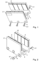
- the figure 1 shows a secondary part according to the prior art.
- a first yoke plate 2.1 and a second yoke plate 2.2 are connected to a spacer 1 in such a way that the two yoke plates 2.1, 2.2 are arranged parallel to one another and opposite one another.
- the yoke plates 2.1, 2.2 carry magnets 3 of alternating polarity, with the polarity magnets 3 lying next to each other differs, as does the polarity of the opposing poles of the magnets 3 facing each other.
- the direction of magnetization of the magnets 3 lying opposite one another is the same in each case, the direction of magnetization of the magnets 3 lying next to one another is rotated by 180 degrees.
- the yoke plates 2.1, 2.2 together with the spacer 1 form a profile with a U-shaped cross section, in which the primary part of the ironless linear motor (not shown here) can move between the magnets 3.
- the primary part and secondary part are each attached to different elements of a machine that are intended to move towards one another.
- a linear guide acts between these elements, which thus also guides the primary part relative to the secondary part.
- the yoke plates 2.1, 2.2 are fastened to the spacer 1 by means of screws 5.
- these screws 5 are inserted through the yoke plates 2.1, 2.2 and screwed into the spacer 1, which has suitable bores with an internal thread for this purpose.
- the screw heads 5.1 of the screws 5 then fix the yoke plates 2.1, 2.2 to the spacer 1.
- Suitable bores and internal threads must therefore be introduced in the spacer 1, and a total of six screws 5 must be screwed into the secondary part for assembly.
- binding screws also known as Chicago screws or English screw posts
- binding screws consist of two parts: a sleeve 4 with an internal thread and a first screw head 4.1, into which a conventional screw 5 with a second screw head 5.1 is screwed.
- the sleeves 4 are inserted through the through holes 6 so that the first screw heads 4.1 fix the first yoke plate 2.1 on the spacer 1.
- the conventional screws 5 are screwed into the sleeves 4 through the second yoke plate 2.2 so that the second screw heads 5.1 fix the second yoke plate 2.2 to the spacer 1.
- a hexagon socket profile for example, can be provided in the first screw head 4.1.
- the sleeves 4 can then be secured against turning with a suitable Allen key or a corresponding device on an assembly table. On an assembly table with such devices, the secondary part does not have to be turned over during assembly, so that a further work step is not required in comparison to the prior art.
- a hexagon socket profile other screw head drives are of course also possible.
- the present invention is in the figure 3 shown.
- the secondary part with its two yoke plates 2.1, 2.2 fastened to the spacer 1 is fastened here to a machine part 9, ie installed in an application.
- the sleeve 4 and the first screw head 4.1 have a common through hole 7 with an internal thread.
- a mounting screw 8 can thus be inserted through a simple hole without its own thread in the machine part 9 and screwed into the sleeve 4 .
- the outlay required to produce the secondary part is further reduced, since separate bores for attachment to the machine part 9 are no longer required on the secondary part, and the preparation of the machine part 9 is also simplified compared to the prior art.
Description
- Diese Schrift betrifft Ausführungsformen eines Sekundärteils für einen Linearmotor, insbesondere Ausführungsformen eines Sekundärteils für einen eisenlosen Linearmotor, sowie Ausführungsformen eines eisenlosen Linearmotors.
- Beispiele für eisenlose Linearmotoren sind aus der
WO 2017/163978 A1 , derUS 2006/0175907 A1 , derJP 2005237087 A JP 2006304438 A EP17196215.2 - Linearmotoren werden oft eingesetzt, wenn es um eine hochgenaue und gegebenenfalls auch schnelle Positionierung von Objekten geht, wie zum Beispiel bei einer Linearachse einer Werkzeugmaschine. Dabei kann das Primärteil des Linearmotors über eine geeignete Schnittstelle unmittelbar mit dem zu bewegenden Maschinenteil oder einem sonstigen Objekt verbunden sein. Das heißt, im Gegensatz zu einem konventionellen Rotationsmotor entfällt hier die Notwendigkeit eines zwischen den Linearmotor und das anzutreibende Objekt geschalteten Getriebes.
- Für Anwendungen, die eine besonders präzise Positionierung erfordern, eignen sich vor allem so genannte eisenlose Linearmotoren, bei denen den Spulen des Primärteils kein Eisenkern zugeordnet ist. Hierdurch lassen sich störende Rastkräfte vermeiden.
- Der oben erwähnten europäischen Patentanmeldung mit der Anmeldenummer
EP17196215.2 - Es ist daher Aufgabe der Erfindung, ein Sekundärteil eines eisenlosen Linearmotors anzugeben, bei dem dieser Aufwand reduziert ist.
- Diese Aufgabe wird gelöst durch eine Anordnung mit einem Maschinenteil und einem am Maschinenteil montierten Sekundärteil gemäß Anspruch 1.
- Weitere Vorteile und Einzelheiten der vorliegenden Erfindung ergeben sich aus der nachfolgenden Beschreibung verschiedener Ausführungsformen anhand der Figuren.
- Dabei zeigt
- Figur 1
- ein Sekundärteil gemäß dem Stand der Technik,
- Figur 2
- ein weiteres Sekundärteil,
- Figur 3
- ein erfindungsgemäßes
- Ausführungsbeispiel eines an einem Maschinenteil montierten Sekundärteils.
- Die
Figur 1 zeigt ein Sekundärteil gemäß dem Stand der Technik. Eine erste Jochplatte 2.1 und eine zweite Jochplatte 2.2 sind so mit einem Abstandshalter 1 verbunden, dass die beiden Jochplatten 2.1, 2.2 parallel zueinander und sich gegenüberliegend angeordnet sind. Die Jochplatten 2.1, 2.2 tragen Magnete 3 abwechselnder Polarität, wobei sich die Polarität nebeneinander liegender Magnete 3 ebenso unterscheidet wie die Polarität der sich jeweils gegenüberliegenden, einander zugewandten Pole der Magnete 3. Die Richtung der Magnetisierung der sich gegenüberliegenden Magnete 3 ist dabei jeweils gleich, die Richtung der Magnetisierung der nebeneinanderliegenden Magnete 3 ist um 180 Grad gedreht. - Die Jochplatten 2.1, 2.2 bilden zusammen mit dem Abstandshalter 1 ein im Querschnitt U-förmiges Profil, in dem sich das hier nicht dargestellte Primärteil des eisenlosen Linearmotors zwischen den Magneten 3 bewegen kann. Primärteil und Sekundärteil werden jeweils an unterschiedlichen Elementen einer Maschine befestigt, die sich zueinander bewegen sollen. Zwischen diesen Elementen wirkt eine Linearführung, die somit auch das Primärteil relativ zum Sekundärteil führt.
- Die Jochplatten 2.1, 2.2 sind mittels Schrauben 5 am Abstandshalter 1 befestigt. Hierzu werden diese Schrauben 5 durch die Jochplatten 2.1, 2.2 gesteckt und in den Abstandshalter 1 geschraubt, der hierfür geeignete Bohrungen mit Innengewinde aufweist. Die Schraubenköpfe 5.1 der Schrauben 5 legen dann die Jochplatten 2.1, 2.2 am Abstandshalter 1 fest. Im Beispiel der
Figur 1 müssen also im Abstandshalter 1 passende Bohrungen und Innengewinde eingebracht werden, und zur Montage insgesamt sechs Schrauben 5 in das Sekundärteil eingeschraubt werden. - Die
Figur 2 zeigt ein Sekundärteil, das mittels spezieller Schrauben hergestellt wurde. Der Abstandshalter 1 weist wenigstens zwei Durchgangsbohrungen 6 auf, die nun kein Gewinde mehr benötigen, und die damit erheblich einfacher zu fertigen sind. Zur Montage werden nun sogenannte Buchschrauben (auch als Chicago-Schraube oder englisch screw post bezeichnet) verwendet, die üblicherweise zum Binden von Büchern oder im Möbelbau eingesetzt werden. Solche Buchschrauben bestehen aus zwei Teilen: Eine Hülse 4 mit Innengewinde und einem ersten Schraubenkopf 4.1, in die eine herkömmliche Schraube 5 mit zweitem Schraubenkopf 5.1 eingeschraubt wird. - Wie in der
Figur 2 gezeigt, werden durch die Durchgangsbohrungen 6 die Hülsen 4 gesteckt, so dass die ersten Schraubenköpfe 4.1 die erste Jochplatte 2.1 am Abstandshalter 1 festlegen. Die herkömmlichen Schrauben 5 werden durch die zweite Jochplatte 2.2 in die Hülsen 4 eingeschraubt so dass die zweiten Schraubenköpfe 5.1 die zweite Jochplatte 2.2 am Abstandshalter 1 festlegen. Um beim Einschrauben der Schraube 5 ein Mitdrehen der Hülse 4 zu vermeiden, kann im ersten Schraubenkopf 4.1 z.B. ein Innensechskantprofil vorgesehen sein. Mit einem passenden Innensechskantschlüssel oder einer entsprechenden Vorrichtung auf einem Montagetisch können dann die Hülsen 4 gegen Mitdrehen gesichert werden. Auf einem Montagetisch mit solchen Vorrichtungen muss das Sekundärteil während der Montage nicht gewendet werden, so dass im Vergleich zum Stand der Technik ein weiterer Arbeitsschritt entfällt. Statt einem Innensechskantprofil sind natürlich auch andere Schraubenkopfantriebe möglich. - Auf diese Weise kann nicht nur auf die Herstellung eines Innengewindes in den Durchgangslöchern 6 des Abstandshalters 1 verzichtet werden, es halbiert sich außerdem die Anzahl der Schraubvorgänge bei der Montage der Jochplatten 2.1, 2.2 am Abstandshalter 1.
- Die vorliegende Erfindung ist in der
Figur 3 gezeigt. Das Sekundärteil mit seinen beiden am Abstandshalter 1 befestigten Jochplatten 2.1, 2.2 ist hier an einem Maschinenteil 9 befestigt, also in einer Applikation verbaut. Anders als in herkömmlichen Buchschrauben weisen die Hülse 4 und der erste Schraubenkopf 4.1 ein gemeinsames Durchgangsloch 7 mit Innengewinde auf. Eine Montageschraube 8 kann also durch eine einfache Bohrung ohne eigenes Gewinde im Maschinenteil 9 gesteckt und in die Hülse 4 geschraubt werden. Der zur Herstellung des Sekundärteils nötige Aufwand ist weiter reduziert, da am Sekundärteil keine separaten Bohrungen zur Befestigung am Maschinenteil 9 mehr nötig sind, und auch die Vorbereitung des Maschinenteils 9 ist gegenüber dem Stand der Technik vereinfacht. - Zwischen der Hülse 4 und den Schrauben 5 empfiehlt sich die Verwendung eines Schraubensicherungslacks, damit sich beim Lösen des Sekundärteils vom Maschinenteil 9 die Jochplatten 2.1, 2.2 nicht vom Abstandshalter 1 lösen.
- Durch die Verwendung eines speziellen Befestigungsmittels kann also der Aufwand zur Herstellung solcher Sekundärteile verringert werden, und zwar indem eine spezielle Ausführungsform dieser Befestigungsmittel mit einem Durchgangsloch 7 mit Innengewinde verwendet wird.
Claims (1)
- Anordnung mit einem Maschinenteil und einem am Maschinenteil montierten Sekundärteil für einen eisenlosen Linearmotor, mit einem Abstandshalter (1) und mit zwei parallel zueinander liegenden Jochplatten (2.1, 2.2), die Magnete (3) abwechselnder Polarität tragen, wobei die erste Jochplatte (2.1) und die zweite Jochplatte (2.2) vom Abstandshalter (1) in einem definierten Abstand gehalten werden und zusammen mit dem Abstandshalter (1) ein im Querschnitt U-förmiges Profil bilden, in dem sich ein Primärteil des Linearmotors bewegen kann, und wobei der Abstandshalter (1) wenigstens zwei Durchgangsbohrungen (6) aufweist, dadurch gekennzeichnet, dass durch die erste Jochplatte (2.1) und durch die Durchgangsbohrungen (6) jeweils eine Hülse (4) mit je einem ersten Schraubenkopf (4.1) und je einem Innengewinde gesteckt sind, wobei die ersten Schraubenköpfe (4.1) die erste Jochplatte (2.1) am Abstandshalter (1) festlegen, und dass jeweils eine Schraube (5) mit je einem zweiten Schraubenkopf (5.1) durch die zweite Jochplatte (2.2) in die jeweilige Hülse (4) eingeschraubt ist, so dass die zweiten Schraubenköpfe (5.1) die zweite Jochplatte (2.2) am Abstandshalter (1) festlegen, und dass die Hülsen (4) und ersten Schraubenköpfe (4.1) jeweils ein gemeinsames Durchgangsloch (7) mit Innengewinde aufweisen, und dass das Sekundärteil mittels einer Montageschraube (8) am Maschinenteil (9) befestigt ist, indem die Montageschraube (8) durch eine Bohrung ohne eigenes Gewinde im Maschinenteil (9) gesteckt und in das Durchgangsloch (7) der Hülse (4) eingeschraubt ist.
Priority Applications (2)
| Application Number | Priority Date | Filing Date | Title |
|---|---|---|---|
| EP18171383.5A EP3567708B1 (de) | 2018-05-09 | 2018-05-09 | Sekundärteil für einen eisenlosen linearmotor |
| US16/407,301 US10931188B2 (en) | 2018-05-09 | 2019-05-09 | Ironless linear motor with parallel yokes separated by a spacer with uninterrupted bore secured with a sleeve and a screw in the sleeve |
Applications Claiming Priority (1)
| Application Number | Priority Date | Filing Date | Title |
|---|---|---|---|
| EP18171383.5A EP3567708B1 (de) | 2018-05-09 | 2018-05-09 | Sekundärteil für einen eisenlosen linearmotor |
Publications (2)
| Publication Number | Publication Date |
|---|---|
| EP3567708A1 EP3567708A1 (de) | 2019-11-13 |
| EP3567708B1 true EP3567708B1 (de) | 2022-03-09 |
Family
ID=62143064
Family Applications (1)
| Application Number | Title | Priority Date | Filing Date |
|---|---|---|---|
| EP18171383.5A Active EP3567708B1 (de) | 2018-05-09 | 2018-05-09 | Sekundärteil für einen eisenlosen linearmotor |
Country Status (2)
| Country | Link |
|---|---|
| US (1) | US10931188B2 (de) |
| EP (1) | EP3567708B1 (de) |
Citations (1)
| Publication number | Priority date | Publication date | Assignee | Title |
|---|---|---|---|---|
| WO2017163978A1 (ja) * | 2016-03-23 | 2017-09-28 | 住友重機械工業株式会社 | リニアモータ、ステージ装置 |
Family Cites Families (20)
| Publication number | Priority date | Publication date | Assignee | Title |
|---|---|---|---|---|
| US5565718A (en) * | 1993-04-23 | 1996-10-15 | Nippon Thompson Co., Ltd. | Direct current linear motor and a guide unit on which it is equipped |
| JP3209644B2 (ja) * | 1994-07-29 | 2001-09-17 | 日本トムソン株式会社 | リニア直流モータ |
| US6140734A (en) * | 1998-04-03 | 2000-10-31 | Nikon Corporation Of Japan | Armature with regular windings and having a high conductor density |
| CH695153A5 (de) * | 2000-08-31 | 2005-12-30 | Etel Sa | Baueinheit eines Linearmotors und Verfahren zur Montage dieser Baueinheit. |
| KR20040101194A (ko) * | 2001-12-21 | 2004-12-02 | 베이 센서스 앤드 시스템즈 캄파니, 인코포레이티 | 평면형 코일을 구비한 선형 음성 코일 작동기 |
| JP3870413B2 (ja) | 2002-08-20 | 2007-01-17 | 株式会社安川電機 | コアレスリニアモータ |
| JP4534194B2 (ja) * | 2004-02-18 | 2010-09-01 | 日立金属株式会社 | 可動コイル型リニアモータ及びその固定子の磁気回路の組立方法 |
| EP2360818A2 (de) * | 2004-05-18 | 2011-08-24 | Kabushiki Kaisha Yaskawa Denki | Anker eines abgedichteten Linearmotors und abgedichteter Linearmotor |
| JP2006304438A (ja) * | 2005-04-19 | 2006-11-02 | Iai:Kk | リニアモータ |
| DE102007014396A1 (de) * | 2007-03-26 | 2008-10-09 | Siemens Ag | Abdeckung für ein Sekundärteil eines Linearmotors |
| JP5423392B2 (ja) * | 2007-06-13 | 2014-02-19 | 株式会社安川電機 | キャンド・リニアモータ電機子およびキャンド・リニアモータ |
| NL2003128C2 (en) * | 2009-07-03 | 2011-01-04 | Tecnotion B V | A method for fabricating an electromagnetic actuator, an electromagnetic actuator, and a charged particle device comprising the same. |
| DE102010004642B4 (de) * | 2010-01-13 | 2012-09-27 | Integrated Dynamics Engineering Gmbh | Magnetaktor sowie Verfahren zu dessen Montage |
| JP5418558B2 (ja) * | 2011-08-23 | 2014-02-19 | 株式会社安川電機 | リニアモータの固定子およびリニアモータ |
| EP2733833B1 (de) * | 2012-11-15 | 2017-07-19 | Etel S. A.. | Primärteil eines eisenlosen Linearmotors |
| US9148047B2 (en) * | 2012-11-30 | 2015-09-29 | Chieftek Precision Co., Ltd. | Coil assembly having separation plates for iron less linear motor |
| NL2012535B1 (en) * | 2014-03-31 | 2016-02-15 | Tecnotion B V | A primary part for a linear motor, a linear motor comprising the same, and method for manufacturing such primary part. |
| EP3093965B1 (de) * | 2015-05-12 | 2017-11-22 | Etel S. A.. | Kurzhubiger linearmotor |
| EP3264575B1 (de) * | 2016-06-28 | 2018-08-22 | Etel S. A.. | Kühlungseinrichtung für den primärteil eines eisenlosen linearmotors |
| EP3471245B1 (de) | 2017-10-12 | 2020-11-18 | Etel S.A. | Sekundärteil für einen eisenlosen linearmotor und eisenloser linearmotor |
-
2018
- 2018-05-09 EP EP18171383.5A patent/EP3567708B1/de active Active
-
2019
- 2019-05-09 US US16/407,301 patent/US10931188B2/en active Active
Patent Citations (1)
| Publication number | Priority date | Publication date | Assignee | Title |
|---|---|---|---|---|
| WO2017163978A1 (ja) * | 2016-03-23 | 2017-09-28 | 住友重機械工業株式会社 | リニアモータ、ステージ装置 |
Also Published As
| Publication number | Publication date |
|---|---|
| US20190348897A1 (en) | 2019-11-14 |
| US10931188B2 (en) | 2021-02-23 |
| EP3567708A1 (de) | 2019-11-13 |
Similar Documents
| Publication | Publication Date | Title |
|---|---|---|
| EP1799400B1 (de) | Verfahren zur herstellung einer nockenwelle | |
| EP0136431B1 (de) | Konstruktion aus Profilstäben | |
| EP0312951A2 (de) | Spannvorrichtung | |
| DE3534214A1 (de) | X-y-tisch mit linearmotor-antrieb | |
| DE2941923A1 (de) | Befestigungsvorrichtung fuer duennwandige bauteile | |
| EP2850719B1 (de) | Statoranordnung für eine elektrische maschine | |
| EP0207215B1 (de) | Linearführung | |
| DE102011121584A1 (de) | Modulares Tragsystem zur Fixierung von Bauteilen | |
| DE102020101064B3 (de) | Werkstückspannvorrichtung | |
| DE102013201305A1 (de) | Wirbelstromdämpfer und Magnetanordnung mit einer Rückschlussplatte hierfür | |
| DE102013113639B3 (de) | Befestigungsvorrichtung zum konzentrischen Befestigen einer Welle an eine Drehgeberwelle und Motorfeedback-System mit dieser Befestigung | |
| DE102013209111B4 (de) | Einspannvorrichtung, insbesondere zur Aufnahme und zum Einspannen eines Bauteils, sowie Einspannsystem mit einer solchen Einspannvorrichtung | |
| EP2372202B1 (de) | Kopplung eines Stellelements eines Ventils mit einem Anschlusselement eines Stellantriebs | |
| DE102008003779A1 (de) | Haltevorrichtung | |
| EP3567708B1 (de) | Sekundärteil für einen eisenlosen linearmotor | |
| DE10207310A1 (de) | Motoreinheit | |
| EP1715975A1 (de) | Hochgeschwindigkeitsfräser | |
| EP0308645B1 (de) | Dehnschraube für Kieferdehnvorrichtungen | |
| DE102013213822B4 (de) | Bauteilanordnung für ein Lenkrad | |
| CH711906A2 (de) | Vorrichtung zum Spannen mehrerer Werkstücke auf einem Teilapparat einer Werkzeugmaschine. | |
| EP3457530B1 (de) | Bauteilsatz, sekundärteil und eisenloser linearmotor | |
| DE3130229C2 (de) | Mehrschneidenwerkzeug | |
| DE1276801B (de) | Kapselgehaeuse, insbesondere fuer elektrische Maschinen | |
| EP0455973A1 (de) | Führungsleiste für Aufzugstür | |
| EP0324112B1 (de) | Justiervorrichtung für einen Einstell-Gewindebolzen |
Legal Events
| Date | Code | Title | Description |
|---|---|---|---|
| PUAI | Public reference made under article 153(3) epc to a published international application that has entered the european phase |
Free format text: ORIGINAL CODE: 0009012 |
|
| STAA | Information on the status of an ep patent application or granted ep patent |
Free format text: STATUS: THE APPLICATION HAS BEEN PUBLISHED |
|
| AK | Designated contracting states |
Kind code of ref document: A1 Designated state(s): AL AT BE BG CH CY CZ DE DK EE ES FI FR GB GR HR HU IE IS IT LI LT LU LV MC MK MT NL NO PL PT RO RS SE SI SK SM TR |
|
| AX | Request for extension of the european patent |
Extension state: BA ME |
|
| STAA | Information on the status of an ep patent application or granted ep patent |
Free format text: STATUS: REQUEST FOR EXAMINATION WAS MADE |
|
| 17P | Request for examination filed |
Effective date: 20200513 |
|
| RBV | Designated contracting states (corrected) |
Designated state(s): AL AT BE BG CH CY CZ DE DK EE ES FI FR GB GR HR HU IE IS IT LI LT LU LV MC MK MT NL NO PL PT RO RS SE SI SK SM TR |
|
| STAA | Information on the status of an ep patent application or granted ep patent |
Free format text: STATUS: EXAMINATION IS IN PROGRESS |
|
| 17Q | First examination report despatched |
Effective date: 20210129 |
|
| GRAP | Despatch of communication of intention to grant a patent |
Free format text: ORIGINAL CODE: EPIDOSNIGR1 |
|
| STAA | Information on the status of an ep patent application or granted ep patent |
Free format text: STATUS: GRANT OF PATENT IS INTENDED |
|
| RIC1 | Information provided on ipc code assigned before grant |
Ipc: H02K 1/34 20060101ALN20210917BHEP Ipc: H02K 1/17 20060101ALN20210917BHEP Ipc: F16B 37/12 20060101ALI20210917BHEP Ipc: F16B 5/02 20060101ALI20210917BHEP Ipc: H02K 41/03 20060101ALI20210917BHEP Ipc: H02K 15/03 20060101AFI20210917BHEP |
|
| INTG | Intention to grant announced |
Effective date: 20211007 |
|
| GRAS | Grant fee paid |
Free format text: ORIGINAL CODE: EPIDOSNIGR3 |
|
| GRAA | (expected) grant |
Free format text: ORIGINAL CODE: 0009210 |
|
| STAA | Information on the status of an ep patent application or granted ep patent |
Free format text: STATUS: THE PATENT HAS BEEN GRANTED |
|
| AK | Designated contracting states |
Kind code of ref document: B1 Designated state(s): AL AT BE BG CH CY CZ DE DK EE ES FI FR GB GR HR HU IE IS IT LI LT LU LV MC MK MT NL NO PL PT RO RS SE SI SK SM TR |
|
| REG | Reference to a national code |
Ref country code: CH Ref legal event code: EP Ref country code: AT Ref legal event code: REF Ref document number: 1474957 Country of ref document: AT Kind code of ref document: T Effective date: 20220315 |
|
| REG | Reference to a national code |
Ref country code: DE Ref legal event code: R096 Ref document number: 502018008986 Country of ref document: DE |
|
| REG | Reference to a national code |
Ref country code: IE Ref legal event code: FG4D Free format text: LANGUAGE OF EP DOCUMENT: GERMAN |
|
| REG | Reference to a national code |
Ref country code: NL Ref legal event code: FP |
|
| REG | Reference to a national code |
Ref country code: LT Ref legal event code: MG9D |
|
| PG25 | Lapsed in a contracting state [announced via postgrant information from national office to epo] |
Ref country code: SE Free format text: LAPSE BECAUSE OF FAILURE TO SUBMIT A TRANSLATION OF THE DESCRIPTION OR TO PAY THE FEE WITHIN THE PRESCRIBED TIME-LIMIT Effective date: 20220309 Ref country code: RS Free format text: LAPSE BECAUSE OF FAILURE TO SUBMIT A TRANSLATION OF THE DESCRIPTION OR TO PAY THE FEE WITHIN THE PRESCRIBED TIME-LIMIT Effective date: 20220309 Ref country code: NO Free format text: LAPSE BECAUSE OF FAILURE TO SUBMIT A TRANSLATION OF THE DESCRIPTION OR TO PAY THE FEE WITHIN THE PRESCRIBED TIME-LIMIT Effective date: 20220609 Ref country code: LT Free format text: LAPSE BECAUSE OF FAILURE TO SUBMIT A TRANSLATION OF THE DESCRIPTION OR TO PAY THE FEE WITHIN THE PRESCRIBED TIME-LIMIT Effective date: 20220309 Ref country code: HR Free format text: LAPSE BECAUSE OF FAILURE TO SUBMIT A TRANSLATION OF THE DESCRIPTION OR TO PAY THE FEE WITHIN THE PRESCRIBED TIME-LIMIT Effective date: 20220309 Ref country code: BG Free format text: LAPSE BECAUSE OF FAILURE TO SUBMIT A TRANSLATION OF THE DESCRIPTION OR TO PAY THE FEE WITHIN THE PRESCRIBED TIME-LIMIT Effective date: 20220609 |
|
| PG25 | Lapsed in a contracting state [announced via postgrant information from national office to epo] |
Ref country code: LV Free format text: LAPSE BECAUSE OF FAILURE TO SUBMIT A TRANSLATION OF THE DESCRIPTION OR TO PAY THE FEE WITHIN THE PRESCRIBED TIME-LIMIT Effective date: 20220309 Ref country code: GR Free format text: LAPSE BECAUSE OF FAILURE TO SUBMIT A TRANSLATION OF THE DESCRIPTION OR TO PAY THE FEE WITHIN THE PRESCRIBED TIME-LIMIT Effective date: 20220610 Ref country code: FI Free format text: LAPSE BECAUSE OF FAILURE TO SUBMIT A TRANSLATION OF THE DESCRIPTION OR TO PAY THE FEE WITHIN THE PRESCRIBED TIME-LIMIT Effective date: 20220309 |
|
| PG25 | Lapsed in a contracting state [announced via postgrant information from national office to epo] |
Ref country code: SM Free format text: LAPSE BECAUSE OF FAILURE TO SUBMIT A TRANSLATION OF THE DESCRIPTION OR TO PAY THE FEE WITHIN THE PRESCRIBED TIME-LIMIT Effective date: 20220309 Ref country code: SK Free format text: LAPSE BECAUSE OF FAILURE TO SUBMIT A TRANSLATION OF THE DESCRIPTION OR TO PAY THE FEE WITHIN THE PRESCRIBED TIME-LIMIT Effective date: 20220309 Ref country code: RO Free format text: LAPSE BECAUSE OF FAILURE TO SUBMIT A TRANSLATION OF THE DESCRIPTION OR TO PAY THE FEE WITHIN THE PRESCRIBED TIME-LIMIT Effective date: 20220309 Ref country code: PT Free format text: LAPSE BECAUSE OF FAILURE TO SUBMIT A TRANSLATION OF THE DESCRIPTION OR TO PAY THE FEE WITHIN THE PRESCRIBED TIME-LIMIT Effective date: 20220711 Ref country code: ES Free format text: LAPSE BECAUSE OF FAILURE TO SUBMIT A TRANSLATION OF THE DESCRIPTION OR TO PAY THE FEE WITHIN THE PRESCRIBED TIME-LIMIT Effective date: 20220309 Ref country code: EE Free format text: LAPSE BECAUSE OF FAILURE TO SUBMIT A TRANSLATION OF THE DESCRIPTION OR TO PAY THE FEE WITHIN THE PRESCRIBED TIME-LIMIT Effective date: 20220309 Ref country code: CZ Free format text: LAPSE BECAUSE OF FAILURE TO SUBMIT A TRANSLATION OF THE DESCRIPTION OR TO PAY THE FEE WITHIN THE PRESCRIBED TIME-LIMIT Effective date: 20220309 |
|
| PG25 | Lapsed in a contracting state [announced via postgrant information from national office to epo] |
Ref country code: PL Free format text: LAPSE BECAUSE OF FAILURE TO SUBMIT A TRANSLATION OF THE DESCRIPTION OR TO PAY THE FEE WITHIN THE PRESCRIBED TIME-LIMIT Effective date: 20220309 Ref country code: IS Free format text: LAPSE BECAUSE OF FAILURE TO SUBMIT A TRANSLATION OF THE DESCRIPTION OR TO PAY THE FEE WITHIN THE PRESCRIBED TIME-LIMIT Effective date: 20220709 Ref country code: AL Free format text: LAPSE BECAUSE OF FAILURE TO SUBMIT A TRANSLATION OF THE DESCRIPTION OR TO PAY THE FEE WITHIN THE PRESCRIBED TIME-LIMIT Effective date: 20220309 |
|
| REG | Reference to a national code |
Ref country code: DE Ref legal event code: R097 Ref document number: 502018008986 Country of ref document: DE |
|
| PLBE | No opposition filed within time limit |
Free format text: ORIGINAL CODE: 0009261 |
|
| STAA | Information on the status of an ep patent application or granted ep patent |
Free format text: STATUS: NO OPPOSITION FILED WITHIN TIME LIMIT |
|
| REG | Reference to a national code |
Ref country code: BE Ref legal event code: MM Effective date: 20220531 |
|
| PG25 | Lapsed in a contracting state [announced via postgrant information from national office to epo] |
Ref country code: MC Free format text: LAPSE BECAUSE OF FAILURE TO SUBMIT A TRANSLATION OF THE DESCRIPTION OR TO PAY THE FEE WITHIN THE PRESCRIBED TIME-LIMIT Effective date: 20220309 Ref country code: LU Free format text: LAPSE BECAUSE OF NON-PAYMENT OF DUE FEES Effective date: 20220509 Ref country code: DK Free format text: LAPSE BECAUSE OF FAILURE TO SUBMIT A TRANSLATION OF THE DESCRIPTION OR TO PAY THE FEE WITHIN THE PRESCRIBED TIME-LIMIT Effective date: 20220309 |
|
| 26N | No opposition filed |
Effective date: 20221212 |
|
| PG25 | Lapsed in a contracting state [announced via postgrant information from national office to epo] |
Ref country code: SI Free format text: LAPSE BECAUSE OF FAILURE TO SUBMIT A TRANSLATION OF THE DESCRIPTION OR TO PAY THE FEE WITHIN THE PRESCRIBED TIME-LIMIT Effective date: 20220309 |
|
| GBPC | Gb: european patent ceased through non-payment of renewal fee |
Effective date: 20220609 |
|
| PG25 | Lapsed in a contracting state [announced via postgrant information from national office to epo] |
Ref country code: IE Free format text: LAPSE BECAUSE OF NON-PAYMENT OF DUE FEES Effective date: 20220509 Ref country code: FR Free format text: LAPSE BECAUSE OF NON-PAYMENT OF DUE FEES Effective date: 20220509 |
|
| PG25 | Lapsed in a contracting state [announced via postgrant information from national office to epo] |
Ref country code: GB Free format text: LAPSE BECAUSE OF NON-PAYMENT OF DUE FEES Effective date: 20220609 Ref country code: BE Free format text: LAPSE BECAUSE OF NON-PAYMENT OF DUE FEES Effective date: 20220531 |
|
| PG25 | Lapsed in a contracting state [announced via postgrant information from national office to epo] |
Ref country code: IT Free format text: LAPSE BECAUSE OF FAILURE TO SUBMIT A TRANSLATION OF THE DESCRIPTION OR TO PAY THE FEE WITHIN THE PRESCRIBED TIME-LIMIT Effective date: 20220309 |
|
| PGFP | Annual fee paid to national office [announced via postgrant information from national office to epo] |
Ref country code: NL Payment date: 20230519 Year of fee payment: 6 Ref country code: DE Payment date: 20220620 Year of fee payment: 6 Ref country code: CH Payment date: 20230602 Year of fee payment: 6 |
|
| PG25 | Lapsed in a contracting state [announced via postgrant information from national office to epo] |
Ref country code: HU Free format text: LAPSE BECAUSE OF FAILURE TO SUBMIT A TRANSLATION OF THE DESCRIPTION OR TO PAY THE FEE WITHIN THE PRESCRIBED TIME-LIMIT; INVALID AB INITIO Effective date: 20180509 |