EP1798130A1 - Dispositif de sécurité pour une installation de transport à câble - Google Patents
Dispositif de sécurité pour une installation de transport à câble Download PDFInfo
- Publication number
- EP1798130A1 EP1798130A1 EP06354040A EP06354040A EP1798130A1 EP 1798130 A1 EP1798130 A1 EP 1798130A1 EP 06354040 A EP06354040 A EP 06354040A EP 06354040 A EP06354040 A EP 06354040A EP 1798130 A1 EP1798130 A1 EP 1798130A1
- Authority
- EP
- European Patent Office
- Prior art keywords
- rope
- tension
- cable
- safety device
- threshold
- Prior art date
- Legal status (The legal status is an assumption and is not a legal conclusion. Google has not performed a legal analysis and makes no representation as to the accuracy of the status listed.)
- Granted
Links
- 238000009434 installation Methods 0.000 title claims description 19
- 230000005294 ferromagnetic effect Effects 0.000 claims description 9
- 230000008878 coupling Effects 0.000 claims description 4
- 238000010168 coupling process Methods 0.000 claims description 4
- 238000005859 coupling reaction Methods 0.000 claims description 4
- 238000000926 separation method Methods 0.000 claims description 3
- 238000012423 maintenance Methods 0.000 abstract 1
- 238000011144 upstream manufacturing Methods 0.000 description 7
- 230000006378 damage Effects 0.000 description 2
- 230000001681 protective effect Effects 0.000 description 2
- 230000002787 reinforcement Effects 0.000 description 2
- 230000001960 triggered effect Effects 0.000 description 2
- 208000027418 Wounds and injury Diseases 0.000 description 1
- 230000000295 complement effect Effects 0.000 description 1
- 238000010276 construction Methods 0.000 description 1
- 230000007423 decrease Effects 0.000 description 1
- 208000014674 injury Diseases 0.000 description 1
- 239000000463 material Substances 0.000 description 1
- 230000013011 mating Effects 0.000 description 1
- 239000011435 rock Substances 0.000 description 1
- 230000035945 sensitivity Effects 0.000 description 1
- 125000006850 spacer group Chemical group 0.000 description 1
Images

Classifications
-
- B—PERFORMING OPERATIONS; TRANSPORTING
- B61—RAILWAYS
- B61B—RAILWAY SYSTEMS; EQUIPMENT THEREFOR NOT OTHERWISE PROVIDED FOR
- B61B11/00—Ski lift, sleigh lift or like trackless systems with guided towing cables only
-
- B—PERFORMING OPERATIONS; TRANSPORTING
- B61—RAILWAYS
- B61B—RAILWAY SYSTEMS; EQUIPMENT THEREFOR NOT OTHERWISE PROVIDED FOR
- B61B12/00—Component parts, details or accessories not provided for in groups B61B7/00 - B61B11/00
- B61B12/06—Safety devices or measures against cable fracture
Definitions
- the invention relates to a safety device for a cable transport installation, for example for a ski lift or chairlift, comprising a rope stretched between a first and a second fixed support, a first end of the rope cooperating with solidarity holding means the first fixed support and ensuring the detachment of the first end of the rope when the rope tension is greater than a predetermined value.
- This type of safety device finds applications in any type of cable transport installation, especially in a ski lift or chairlift, the rope used to delimit a prohibited area for users of the facility.
- the safety device is installed in the upstream station of a detachable ski lift or a cable ski lift with release to the last pylon.
- the force applied laterally on the latter increases its tension until the end of the rope and the holding means are detached.
- the end of the rope engages a contactor whose change of state causes the cut-off of the supply of the cable drive means of the transport installation.
- the safety device is installed after the end of the track, the rope extending between two fixed supports on either side of the prolongation of the track.
- the device ensures the cable stops when the user begins to overrun the end of the track by pulling the rope, for avoid that the user is pulled by his equipment beyond the end of the track (which would be very dangerous), or to prevent a second user, also being hooked, do not hit him.
- the cable drive means can be put back into service even though the rope is not put back in place, that is to say stretched again between the fixed supports, which represents a first risk.
- a second user can strike a first user, for example, coming out of the prohibited zone theoretically delimited by the rope, or the second user can himself enter the forbidden zone without causing the cable to stop, the wire then being more in place.
- the stopping of the cable being caused by the separation of the ferromagnetic armature and the permanent magnet constituting the holding means if the force applied to the rope by a user is too low to cause said disconnection, the latter can still be in contact with the rope stretched or close, that is to say on the border of the forbidden zone, without the cable is stopped.
- the user, then blocked against the rope may suffer bodily injury due to the traction force of the apparatus, which represents a second risk. A second user is also likely to come up against him.
- the end of the rope opposite to that having the ferromagnetic armature is often attached with a screwing device.
- the ferromagnetic armature remains in contact with the permanent magnet while the rope is no longer tensioned between the fixed supports.
- the cable drive means of the installation then continue to operate, constituting a major risk for the users of the installation.
- the invention aims to overcome these disadvantages by providing a safety device simple and inexpensive design, providing enhanced security for users of the facility.
- this object is achieved by the fact that the second end of the rope is connected to an electromechanical switch secured to the second fixed support by ensuring the automatic tripping and stopping of the cable of the installation when the voltage of the strand is below a low threshold or above a high threshold.
- such a safety device makes it possible to ensure the automatic stop of the cable in the event of rupture of the junctions of the rope with the fixed or breaking supports of the rope itself.
- the cable drive means can not be put back into service until the rope tension felt by the electromechanical switch is not greater than the low threshold, which corresponds to at a stretched position of the rope.
- a properly selected high threshold will ensure the cable stop of the installation.
- a transport facility 10 comprises a cable 11 extending in a closed loop between an upstream station 12 and a downstream station (not shown).
- the downstream station comprises means for driving a driving pulley to move the cable 11 to which are suspended equipment 14.
- the upstream station 12 comprises a pulley 13 for guiding the cable 11.
- the transport installation 10 constitutes , in the example, a ski lift with release of poles 14 under the pulley 13.
- the upstream station 12 is built above a slope 15 and has an arrival platform 16.
- the dotted line 17 represents the level of the snow.
- the dotted line 17 comprises a descent 18 below the pulley 13 to allow the user 19 to release his pole 14 while maintaining a sufficient speed to leave the upstream station 12.
- the pulley 13 is pivotally mounted along a vertical axis on a "lorry" 20 supported by a vertical pylon 21 and an inclined pylon 22, of upper section.
- the inclined pylon 22 extends from top to bottom while approaching the vertical pylon 21.
- the upstream station 12 comprises, in accordance with the invention, a safety device 30 comprising a rope 31 stretched between the inclined pylon 22 and a post 23 anchored in the ground so that the rope 31 extends generally in the axis of the transport installation 10.
- the post 23 and the inclined pylon 22 constitute respectively a first and a second fixed supports, sufficiently rigid for the tensioning of the rope 31.
- the safety device 30 is intended to cause the power supply of the driving pulley drive means when a user 19 enters the prohibited zone delimited by the rope 31.
- the rope 31 of the safety device 30 comprises, at a first end, a ferromagnetic armature 32, in the form of a disc, designed to cooperate with a permanent magnet 33 integral with the pole 23. More specifically, the rope 31 comprises a cable 34 of any material and very low elasticity. A first cable clamp 35 is attached to the end of the cable 34 with a lug 36. The cable loop 34 thus formed passes through a ring 37 integral with the ferromagnetic armature 32.
- the permanent magnet 33 is maintained by screwing into the post 23, by means of a screw 38 cooperating with a clamping plate 39 attached to the inside of the post 23, the permanent magnet 33 being interposed between the head of the screw 38 and a spacer 40
- the permanent magnet 33 constitutes, in cooperation with the ferromagnetic armature 32, means for holding the first end of the rope 31, ensuring the separation when the tension of the rope 31 becomes greater than 30. a predetermined value.
- a cylinder integral with the post 23 has a ball inside with spring return.
- the ball is intended to fit into a complementary housing arranged on the outer surface of a coupling member integral with the first end of the rope 31, said coupling member being inserted into the barrel.
- the housing has a suitable contour such as a ramp.
- the other end of the rope 31 is connected to an electromechanical switch 41 integral with the inclined mast 22 by means of screws 48. More specifically, the end of the cable 34 comprises a second cable clamp 42 with a second terminal 43. tensioner 44 is interposed between the loop thus formed and a spring 45 itself connected to a ring 46 of the electromechanical switch 41. As illustrated in Figure 5, the electromechanical switch 41, the spring 45, the tensioner 44 and the second cable clamp 42 are covered with a protective mattress 47. Similarly, the other end of the rope 31 may be covered by a protective sleeve (not shown).
- the spring 45 provides a nominal voltage in the rope 31, while the tensioner 44 allows adjustment of said nominal voltage.
- the spring 45 is particularly useful for lowering the sensitivity of the safety device 30.
- the electromechanical switch 41 is integrated in the supply system of the drive pulley drive means so that the triggering of the switch 41 causes the cable 11 to stop.
- the triggering occurs automatically when the tension of the rope 31 felt by the switch 41 is lower than a threshold low or higher than a high threshold, the high and low thresholds being predetermined.
- the electromechanical switch 41 is triggered immediately after its resetting because the tension of the rope 31 felt by the switch 41 is lower than the low threshold .
- the switch 41 is reset, usually manually, to drive the cable 11 again, subject to a tension of the rope 31 between the high and low thresholds.
- the resetting of the switch 41 after triggering is prohibited if the tension of the rope 31 is lower than the low threshold and / or if the voltage is greater than the threshold high.
- the high and low thresholds are adjustable because the value of the nominal voltage required for a proper arrangement of the rope 31 increases with the length of said rope 31. In practice, the high and low thresholds are such that the nominal tension of the rope 31 is between these two values.
- the transport installation 10 described above is only an illustrative example in no way limiting as to the field of application of the invention.
- the safety device 30 can be used in any cable transport installation, especially in any type of ski lift or chairlift.
- the rope 31 can be stretched between any type of fixed supports (fixed or removable posts, pylons, rocks, walls, cables %) without departing from the scope of the invention.
Landscapes
- Engineering & Computer Science (AREA)
- Transportation (AREA)
- Mechanical Engineering (AREA)
- Emergency Lowering Means (AREA)
- Ropes Or Cables (AREA)
- Laying Of Electric Cables Or Lines Outside (AREA)
- Catching Or Destruction (AREA)
- Warehouses Or Storage Devices (AREA)
- Control Of Conveyors (AREA)
- Maintenance And Inspection Apparatuses For Elevators (AREA)
- Electrical Discharge Machining, Electrochemical Machining, And Combined Machining (AREA)
- Types And Forms Of Lifts (AREA)
Abstract
Description
- L'invention concerne un dispositif de sécurité pour une installation de transport à câble, par exemple pour un téléski ou un télésiège, comprenant un filin tendu entre un premier et un deuxième supports fixes, une première extrémité du filin coopérant avec des moyens de maintien solidaires du premier support fixe et assurant la désolidarisation de la première extrémité du filin lorsque la tension du filin est supérieure à une valeur prédéterminée.
- Ce genre de dispositif de sécurité trouve applications dans tout type d'installation de transport à câble, notamment dans un téléski ou un télésiège, le filin servant à délimiter une zone interdite pour les utilisateurs de l'installation. Par exemple, le dispositif de sécurité est installé en gare amont d'un téléski débrayable ou d'un téléski à enrouleurs avec lâcher au dernier pylône. Lorsqu'un utilisateur de l'installation pénètre, souvent par inadvertance, dans la zone interdite délimitée par le filin tendu, l'effort appliqué latéralement sur ce dernier augmente sa tension jusqu'à désolidariser l'extrémité du filin et les moyens de maintien. Dans son mouvement, l'extrémité du filin enclenche un contacteur dont le changement d'état provoque la coupure de l'alimentation des moyens d'entraînement du câble de l'installation de transport. Par exemple avec un téléski à enrouleurs avec lâcher au dernier pylône, le dispositif de sécurité est installé après la fin de la piste, le filin s'étendant entre deux supports fixes de part et d'autre du prolongement de la piste. Lorsqu'un utilisateur oublie de lâcher son agrès ou reste accroché à ce dernier, le dispositif assure l'arrêt du câble lorsque l'utilisateur commence à dépasser la fin de piste en tirant sur le filin, pour éviter que l'utilisateur ne soit tiré par son agrès au-delà de la fin de piste (ce qui serait très dangereux), ou pour éviter qu'un deuxième utilisateur, lui aussi étant resté accroché, ne vienne le heurter.
- Ce dispositif de sécurité n'est pas complètement satisfaisant concernant la sécurité apportée. D'abord, par un réarmement manuel, les moyens d'entraînement du câble peuvent être remis en service bien que le filin ne soit pas remis en place, c'est-à-dire tendu à nouveau entre les supports fixes, ce qui représente un premier risque. Un deuxième utilisateur peut venir heurter un premier utilisateur par exemple sortant de la zone interdite théoriquement délimitée par le filin, ou bien le deuxième utilisateur peut lui-même pénétrer dans la zone interdite sans provoquer l'arrêt du câble, le filin n'étant alors plus en place.
- D'autre part, l'arrêt du câble étant provoqué par la désolidarisation de l'armature ferromagnétique et de l'aimant permanent constituant les moyens de maintien, si l'effort appliqué au filin par un utilisateur est trop faible pour engendrer ladite désolidarisation, ce dernier peut encore être en contact avec le filin tendu ou à proximité, c'est-à-dire à la frontière de la zone interdite, sans que le câble soit à l'arrêt. L'utilisateur, alors bloqué contre le filin, risque de subir des dommages corporels en raison de l'effort de traction de l'agrès, ce qui représente un deuxième risque. Un deuxième utilisateur est aussi susceptible de venir le heurter.
- Par ailleurs, l'extrémité du filin opposée à celle ayant l'armature ferromagnétique est souvent attachée avec un dispositif de vissage. En cas de rupture du dispositif, l'armature ferromagnétique reste en contact avec l'aimant permanent tandis que le filin n'est plus tendu entre les supports fixes. Les moyens d'entraînement du câble de l'installation continuent alors de fonctionner, constituant un risque majeur pour les utilisateurs de l'installation.
- L'invention a pour but de pallier ces inconvénients en proposant un dispositif de sécurité de conception simple et peu onéreuse, assurant une sécurité renforcée pour les utilisateurs de l'installation.
- Selon l'invention, ce but est atteint par le fait que la deuxième extrémité du filin est liée à un commutateur électro-mécanique solidaire du deuxième support fixe en assurant le déclenchement automatique et l'arrêt du câble de l'installation lorsque la tension du filin est inférieure à un seuil bas ou supérieure à un seuil haut.
- Avec le déclenchement dû au seuil bas, un tel dispositif de sécurité permet d'assurer l'arrêt automatique du câble en cas de rupture des jonctions du filin avec les supports fixes ou de rupture du filin lui-même. De plus, quel que soit le type de réarmement, les moyens d'entraînement du câble ne peuvent pas être remis en service tant que la tension du filin ressentie par le commutateur électro-mécanique n'est pas supérieure au seuil bas, ce qui correspond à une position tendue du filin. En outre, même dans les cas où l'effort appliqué au filin par l'utilisateur n'est pas suffisant pour désolidariser la première extrémité du filin et les moyens de maintien, un seuil haut correctement choisi garantira l'arrêt du câble de l'installation.
- D'autres avantages et caractéristiques ressortiront plus clairement de la description qui va suivre de modes particuliers de réalisation de l'invention donnés à titre d'exemples non limitatifs et représentés aux dessins annexés, dans lesquels :
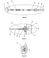
- la figure 1 est une représentation schématique de la gare amont d'un exemple d'installation de transport à câble pour laquelle un exemple de dispositif de sécurité conforme à l'invention est mis en oeuvre,
- la figure 2 est une vue de face du dispositif de sécurité de la figure 1,
- la figure 3 représente la vue de détail A de la figure 2,
- la figure 4 représente la vue de détail B de la figure 2,
- la figure 5 est une vue suivant la direction C d'une coupe transversale du dispositif de sécurité de la figure 2.
- Sur la figure 1, une installation de transport 10 comporte un câble 11 s'étendant en boucle fermée entre une gare amont 12 et une gare avale (non représentée). La gare avale comporte des moyens d'entraînement d'une poulie motrice pour mettre en mouvement le câble 11 auquel sont suspendus des agrès 14. La gare amont 12 comporte une poulie 13 pour le guidage du câble 11. L'installation de transport 10 constitue, dans l'exemple, un téléski avec lâcher de perches 14 sous la poulie 13. La gare amont 12 est construite au-dessus d'une pente 15 et comporte une plateforme d'arrivée 16. La ligne pointillée 17 représente le niveau de la neige. La ligne pointillée 17 comporte une descente 18 en deçà de la poulie 13 pour permettre à l'utilisateur 19 de lâcher sa perche 14 en conservant une vitesse suffisante pour sortir de la gare amont 12.
- La poulie 13 est montée à pivotement suivant un axe vertical sur un « lorry » 20 supporté par un pylône vertical 21 et par un pylône incliné 22, de section supérieure. Le pylône incliné 22 s'étend de haut en bas en s'approchant du pylône vertical 21.
- La gare amont 12 comporte, conformément à l'invention, un dispositif de sécurité 30 comprenant un filin 31 tendu entre le pylône incliné 22 et un poteau 23 ancré dans le sol de telle manière que le filin 31 s'étend globalement dans l'axe de l'installation de transport 10. Le poteau 23 et le pylône incliné 22 constituent respectivement un premier et un deuxième supports fixes, suffisamment rigide pour la mise en tension du filin 31. Le dispositif de sécurité 30 est destiné à provoquer la coupure de l'alimentation des moyens d'entraînement de la poulie motrice lorsqu'un utilisateur 19 pénètre dans la zone interdite délimitée par le filin 31.
- En référence aux figures 2 à 5, le filin 31 du dispositif de sécurité 30 comporte, à une première extrémité, une armature ferromagnétique 32, en forme de disque dans l'exemple, destinée à coopérer avec un aimant permanent 33 solidaire du poteau 23. Plus précisément, le filin 31 comporte un câble 34 de matière quelconque et d'élasticité très faible. Un premier serre-câble 35 est rapporté à l'extrémité du câble 34 avec une cosse 36. La boucle de câble 34 ainsi formée passe au travers d'un anneau 37 solidaire de l'armature ferromagnétique 32. L'aimant permanent 33 est maintenu par vissage dans le poteau 23, par l'intermédiaire d'une vis 38 coopérant avec une plaque de serrage 39 rapportée à l'intérieur du poteau 23, l'aimant permanent 33 étant intercalé entre la tête de la vis 38 et une entretoise 40 prenant appui à l'extérieur du poteau 38. L'aimant permanent 33 constitue, en coopération avec l'armature ferromagnétique 32, des moyens de maintien de la première extrémité du filin 31, assurant la désolidarisation lorsque la tension du filin 31 devient supérieure à une valeur prédéterminée.
- D'autres moyens de maintien équivalents peuvent être utilisés. Dans une variante non représentée, un barillet solidaire du poteau 23 comporte intérieurement une bille avec rappel par ressort. La bille est destinée à s'insérer dans un logement complémentaire agencé sur la surface extérieure d'un membre d'accouplement solidaire de la première extrémité du filin 31, ledit membre d'accouplement venant s'insérer dans le barillet. Pour une valeur prédéterminée de la tension du filin 31, la bille s'échappe du logement pour libérer le membre d'accouplement. A cet effet, le logement comporte un contour approprié tel qu'une rampe.
- L'autre extrémité du filin 31 est liée à un commutateur électro-mécanique 41 solidaire du pylône incliné 22 grâce à des vis 48. Plus précisément, l'extrémité du câble 34 comporte un deuxième serre-câble 42 avec une deuxième cosse 43. Un tendeur 44 est intercalé entre la boucle ainsi formée et un ressort 45 lui-même lié à un anneau 46 du commutateur électro-mécanique 41. Comme l'illustre la figure 5, le commutateur électro-mécanique 41, le ressort 45, le tendeur 44 et le deuxième serre-câble 42 sont recouverts d'un matelas de protection 47. De manière identique, l'autre extrémité du filin 31 peut être recouverte par un manchon de protection (non représenté).
- Le ressort 45 procure une tension nominale dans le filin 31, tandis que le tendeur 44 permet un réglage de ladite tension nominale. Le ressort 45 est particulièrement utile pour abaisser la sensibilité du dispositif de sécurité 30.
- Le commutateur électro-mécanique 41 est intégré dans le système d'alimentation des moyens d'entraînement de la poulie motrice de telle manière que le déclenchement du commutateur 41 provoque l'arrêt du câble 11. Le déclenchement survient automatiquement lorsque la tension du filin 31 ressentie par le commutateur 41 est inférieure à un seuil bas ou supérieure à un seuil haut, les seuils hauts et bas étant prédéterminés.
- Lorsqu'un utilisateur 19 oublie de lâcher sa agrès 14 ou reste accroché à ce dernier, l'utilisateur 19 entre en contact avec le filin 31 tendu entre le pylône incliné 22 et le poteau 23, provoquant une augmentation de sa tension à partir de la tension nominale. En cas de dépassement du seuil haut, le commutateur électro-mécanique 41 se déclenche automatiquement et le câble 11 s'arrête pour assurer la sécurité de l'utilisateur 19. L'installation 10 reste dans cet état tant que le commutateur électro-mécanique 41 n'est pas réarmé. De plus, si les efforts internes de traction dans le filin 31 dus aux efforts extérieurs appliqués par l'utilisateur 19 continuent d'augmenter, l'armature ferromagnétique 32 se désolidarise de l'aimant permanent 33 et le filin 31 libère le passage vers la zone interdite pour ne pas blesser l'utilisateur 19. Le seuil haut est compris entre la tension nominale et la valeur prédéterminée de la tension provoquant la désolidarisation de l'armature ferromagnétique 32.
- Tant que le filin 31 n'est pas remis en place entre le pylône incliné 22 et le poteau 23, le commutateur électro-mécanique 41 se déclenche immédiatement après son réarmement car la tension du filin 31 ressentie par le commutateur 41 est inférieure au seuil bas. Après la remise en place du filin 31, le commutateur 41 est réarmé, généralement manuellement, pour entraîner à nouveau le câble 11, sous réserve d'une tension du filin 31 comprise entre les seuils haut et bas. Pour un renforcement de la sécurité apportée, dans certaines variantes de construction du commutateur électro-mécanique 41, le réarmement du commutateur 41 après déclenchement est interdit si la tension du filin 31 est inférieure au seuil bas et/ou si la tension est supérieure au seuil haut.
- Les seuils haut et bas sont réglables car la valeur de la tension nominale nécessaire pour une disposition correcte du filin 31 augmente avec la longueur dudit filin 31. En pratique, les seuils haut et bas sont tels que la tension nominale du filin 31 est comprise entre ces deux valeurs.
- En cas de rupture du filin 31 ou de l'une des jonctions avec le pylône incliné 22 et le poteau 23, la tension du filin 31 ressentie par le commutateur électro-mécanique 41 sur l'anneau 46 diminue ou devient nulle en provoquant le déclenchement automatique du commutateur 41. Le câble 11 s'arrête alors pour un renforcement de sécurité, notamment en supprimant la possibilité qu'un utilisateur 19 puisse pénétrer dans la zone interdite sans provoquer l'arrêt de l'installation 10.
- L'installation de transport 10 décrite précédemment n'est qu'un exemple illustratif en aucun cas limitatif quant au domaine d'application de l'invention. Le dispositif de sécurité 30 peut être utilisé dans toute installation de transport à câble, notamment dans tout type de téléski ou de télésiège. Enfin, le filin 31 peut être tendu entre tout type de supports fixes (poteaux fixes ou amovibles, pylônes, rochers, murs, câbles...) sans sortir du cadre de l'invention.
Claims (8)
- Dispositif de sécurité (30) pour une installation de transport (10) à câble (11), par exemple pour un téléski ou un télésiège, comprenant un filin (31) tendu entre un premier et un deuxième supports fixes (23, 22), une première extrémité du filin (31) coopérant avec des moyens de maintien solidaires du premier support fixe (23) et assurant la désolidarisation de la première extrémité du filin (31) lorsque la tension du filin (31) est supérieure à une valeur prédéterminée, caractérisé en ce que la deuxième extrémité du filin (31) est liée à un commutateur électro-mécanique (41) solidaire du deuxième support fixe (22) en assurant le déclenchement automatique et l'arrêt du câble (11) de l'installation (10) lorsque la tension du filin (31) est inférieure à un seuil bas ou supérieure à un seuil haut.
- Dispositif selon la revendication 1, caractérisé en ce que les moyens de maintien comportent un aimant permanent (33) destiné à coopérer avec une armature ferromagnétique (32) solidaire de la première extrémité du filin (31).
- Dispositif selon la revendication 1, caractérisé en ce que les moyens de maintien comportent un barillet muni intérieurement d'une bille avec rappel par ressort, la bille s'insérant dans un logement d'un membre d'accouplement solidaire de la première extrémité du filin (31) et s'échappant pour libérer le membre d'accouplement du logement pour ladite valeur prédéterminée de la tension du filin (31).
- Dispositif selon l'une des revendications 1 à 3, caractérisé en ce que le réarmement du commutateur électro-mécanique (41) est interdit si la tension du filin (31) est inférieure au seuil bas.
- Dispositif selon l'une des revendications 1 à 4, caractérisé en ce que le réarmement du commutateur électro-mécanique (41) est interdit si la tension du filin (31) est supérieure au seuil haut.
- Dispositif selon l'une des revendications 1 à 5, caractérisé en ce que les seuils haut et bas sont réglables en fonction de la longueur du filin (31).
- Dispositif selon l'une quelconque des revendications 1 à 6, caractérisé en ce que le filin (31) comporte un ressort (45) procurant une tension nominale dans le filin (31) comprise entre les seuils haut et bas.
- Dispositif selon la revendication 7, caractérisé en ce que le filin (31) comporte un tendeur (44) permettant le réglage de la tension nominale dans le filin (31).
Priority Applications (1)
| Application Number | Priority Date | Filing Date | Title |
|---|---|---|---|
| PL06354040T PL1798130T3 (pl) | 2005-12-15 | 2006-11-29 | Urządzenie zabezpieczające do urządzeń transportu linowego |
Applications Claiming Priority (1)
| Application Number | Priority Date | Filing Date | Title |
|---|---|---|---|
| FR0512748A FR2894918B1 (fr) | 2005-12-15 | 2005-12-15 | Dispositif de securite pour une installation de transport a cable |
Publications (2)
| Publication Number | Publication Date |
|---|---|
| EP1798130A1 true EP1798130A1 (fr) | 2007-06-20 |
| EP1798130B1 EP1798130B1 (fr) | 2008-09-03 |
Family
ID=37211549
Family Applications (1)
| Application Number | Title | Priority Date | Filing Date |
|---|---|---|---|
| EP06354040A Not-in-force EP1798130B1 (fr) | 2005-12-15 | 2006-11-29 | Dispositif de sécurité pour une installation de transport à câble |
Country Status (5)
| Country | Link |
|---|---|
| EP (1) | EP1798130B1 (fr) |
| AT (1) | ATE407045T1 (fr) |
| DE (1) | DE602006002583D1 (fr) |
| FR (1) | FR2894918B1 (fr) |
| PL (1) | PL1798130T3 (fr) |
Cited By (1)
| Publication number | Priority date | Publication date | Assignee | Title |
|---|---|---|---|---|
| CN115282509A (zh) * | 2022-07-28 | 2022-11-04 | 国网河北省电力有限公司超高压分公司 | 一种用于变压器检修过程中安全带悬挂的装置及方法 |
Citations (4)
| Publication number | Priority date | Publication date | Assignee | Title |
|---|---|---|---|---|
| US3209703A (en) * | 1963-10-23 | 1965-10-05 | John P Brebner | Ski lift safety device |
| FR2163987A5 (fr) * | 1971-12-08 | 1973-07-27 | Pomagalski Sa | |
| EP0423027A1 (fr) * | 1989-10-11 | 1991-04-17 | VINCENT DE ARAUJO, Manuel Alexandre | Dispositif de sécurité actionnable par un corps en mouvement, en particulier portillon de sécurité |
| FR2801858A1 (fr) * | 1999-12-02 | 2001-06-08 | Doppelmayr Service | Lacher sous poulie pour teleski a agres type enrouleur de corde |
-
2005
- 2005-12-15 FR FR0512748A patent/FR2894918B1/fr not_active Expired - Fee Related
-
2006
- 2006-11-29 PL PL06354040T patent/PL1798130T3/pl unknown
- 2006-11-29 DE DE602006002583T patent/DE602006002583D1/de not_active Expired - Fee Related
- 2006-11-29 EP EP06354040A patent/EP1798130B1/fr not_active Not-in-force
- 2006-11-29 AT AT06354040T patent/ATE407045T1/de active
Patent Citations (4)
| Publication number | Priority date | Publication date | Assignee | Title |
|---|---|---|---|---|
| US3209703A (en) * | 1963-10-23 | 1965-10-05 | John P Brebner | Ski lift safety device |
| FR2163987A5 (fr) * | 1971-12-08 | 1973-07-27 | Pomagalski Sa | |
| EP0423027A1 (fr) * | 1989-10-11 | 1991-04-17 | VINCENT DE ARAUJO, Manuel Alexandre | Dispositif de sécurité actionnable par un corps en mouvement, en particulier portillon de sécurité |
| FR2801858A1 (fr) * | 1999-12-02 | 2001-06-08 | Doppelmayr Service | Lacher sous poulie pour teleski a agres type enrouleur de corde |
Cited By (1)
| Publication number | Priority date | Publication date | Assignee | Title |
|---|---|---|---|---|
| CN115282509A (zh) * | 2022-07-28 | 2022-11-04 | 国网河北省电力有限公司超高压分公司 | 一种用于变压器检修过程中安全带悬挂的装置及方法 |
Also Published As
| Publication number | Publication date |
|---|---|
| ATE407045T1 (de) | 2008-09-15 |
| EP1798130B1 (fr) | 2008-09-03 |
| PL1798130T3 (pl) | 2009-02-27 |
| DE602006002583D1 (de) | 2008-10-16 |
| FR2894918A1 (fr) | 2007-06-22 |
| FR2894918B1 (fr) | 2008-02-29 |
Similar Documents
| Publication | Publication Date | Title |
|---|---|---|
| EP3141285B1 (fr) | Dispositif de sécurité autobloquant pour corde d'escalade | |
| FR2867082A1 (fr) | Dispositif a bec basculant pour la mise en place d'une canule dans une veine | |
| FR3022003A1 (fr) | Dispositif de connexion de securite a deconnexion automatique en cas de traction superieure a une valeur limite reglable | |
| EP1798130B1 (fr) | Dispositif de sécurité pour une installation de transport à câble | |
| EP0112265B1 (fr) | Dispositif de descente automatique rapide pour pantographe | |
| EP2974775A1 (fr) | Bloqueur pour la remontée sur corde | |
| EP0734743A1 (fr) | Organe d'absorption d'énergie associé à une longe d'assurance | |
| EP1495674A1 (fr) | Muselière | |
| FR2742474A3 (fr) | Porte coulissante munie d'un dispositif d'ouverture ou de fermeture de secours | |
| EP0863827B1 (fr) | Dispositif de trainage de skieurs | |
| EP0423027B1 (fr) | Dispositif de sécurité actionnable par un corps en mouvement, en particulier portillon de sécurité | |
| WO2006035138A1 (fr) | Dispositif assureur descendeur autobloquant pour cordes de tout diametre | |
| FR2943693A1 (fr) | Barriere apte a se degonder et equipee d'un dispositif de regondage automatique. | |
| EP4066906B1 (fr) | Dispositif de fixation à un point d'ancrage et procédé d'utilisation du dispositif de fixation | |
| FR3057170A1 (fr) | Dispositif antichute a frein d'enroulement | |
| FR2831619A1 (fr) | Systeme de crochet largable | |
| EP0194190B1 (fr) | Dispositif pour favoriser le dégagement des skieurs à l'arrivée d'un teleski du type à pinces débrayables | |
| FR2931176A1 (fr) | Dispositif de signalisation pour avertir d'une interdiction de s'amarrer a un bollard dans une ecluse | |
| FR2712916A1 (fr) | Dispositif de tension d'un câble de sécurité. | |
| EP1063139A1 (fr) | Dispositif de sécurité pour une station d'arrivée d'une installation de convoyage | |
| FR3007733A1 (fr) | Dispositif de traction sous marine pour la plongee sous marine | |
| FR3109092A1 (fr) | Dispositif d’assurage à double mousquetons | |
| FR2845970A1 (fr) | Cerf volant de traction securise | |
| CA2240708C (fr) | Dispositif de trainage de skieurs | |
| FR2952543A1 (fr) | Systeme de securite anti-chute |
Legal Events
| Date | Code | Title | Description |
|---|---|---|---|
| PUAI | Public reference made under article 153(3) epc to a published international application that has entered the european phase |
Free format text: ORIGINAL CODE: 0009012 |
|
| AK | Designated contracting states |
Kind code of ref document: A1 Designated state(s): AT BE BG CH CY CZ DE DK EE ES FI FR GB GR HU IE IS IT LI LT LU LV MC NL PL PT RO SE SI SK TR |
|
| AX | Request for extension of the european patent |
Extension state: AL BA HR MK YU |
|
| 17P | Request for examination filed |
Effective date: 20071024 |
|
| AKX | Designation fees paid |
Designated state(s): AT BE BG CH CY CZ DE DK EE ES FI FR GB GR HU IE IS IT LI LT LU LV MC NL PL PT RO SE SI SK TR |
|
| GRAP | Despatch of communication of intention to grant a patent |
Free format text: ORIGINAL CODE: EPIDOSNIGR1 |
|
| GRAS | Grant fee paid |
Free format text: ORIGINAL CODE: EPIDOSNIGR3 |
|
| GRAA | (expected) grant |
Free format text: ORIGINAL CODE: 0009210 |
|
| AK | Designated contracting states |
Kind code of ref document: B1 Designated state(s): AT BE BG CH CY CZ DE DK EE ES FI FR GB GR HU IE IS IT LI LT LU LV MC NL PL PT RO SE SI SK TR |
|
| REG | Reference to a national code |
Ref country code: GB Ref legal event code: FG4D Free format text: NOT ENGLISH |
|
| REG | Reference to a national code |
Ref country code: CH Ref legal event code: EP |
|
| REG | Reference to a national code |
Ref country code: IE Ref legal event code: FG4D Free format text: LANGUAGE OF EP DOCUMENT: FRENCH |
|
| REF | Corresponds to: |
Ref document number: 602006002583 Country of ref document: DE Date of ref document: 20081016 Kind code of ref document: P |
|
| REG | Reference to a national code |
Ref country code: CH Ref legal event code: NV Representative=s name: CABINET ROLAND NITHARDT CONSEILS EN PROPRIETE INDU |
|
| REG | Reference to a national code |
Ref country code: SE Ref legal event code: TRGR |
|
| REG | Reference to a national code |
Ref country code: GR Ref legal event code: EP Ref document number: 20080403358 Country of ref document: GR |
|
| PG25 | Lapsed in a contracting state [announced via postgrant information from national office to epo] |
Ref country code: NL Free format text: LAPSE BECAUSE OF FAILURE TO SUBMIT A TRANSLATION OF THE DESCRIPTION OR TO PAY THE FEE WITHIN THE PRESCRIBED TIME-LIMIT Effective date: 20080903 Ref country code: LT Free format text: LAPSE BECAUSE OF FAILURE TO SUBMIT A TRANSLATION OF THE DESCRIPTION OR TO PAY THE FEE WITHIN THE PRESCRIBED TIME-LIMIT Effective date: 20080903 |
|
| PGFP | Annual fee paid to national office [announced via postgrant information from national office to epo] |
Ref country code: DE Payment date: 20081127 Year of fee payment: 3 |
|
| PG25 | Lapsed in a contracting state [announced via postgrant information from national office to epo] |
Ref country code: SI Free format text: LAPSE BECAUSE OF FAILURE TO SUBMIT A TRANSLATION OF THE DESCRIPTION OR TO PAY THE FEE WITHIN THE PRESCRIBED TIME-LIMIT Effective date: 20080903 Ref country code: ES Free format text: LAPSE BECAUSE OF FAILURE TO SUBMIT A TRANSLATION OF THE DESCRIPTION OR TO PAY THE FEE WITHIN THE PRESCRIBED TIME-LIMIT Effective date: 20081214 Ref country code: LV Free format text: LAPSE BECAUSE OF FAILURE TO SUBMIT A TRANSLATION OF THE DESCRIPTION OR TO PAY THE FEE WITHIN THE PRESCRIBED TIME-LIMIT Effective date: 20080903 |
|
| PGFP | Annual fee paid to national office [announced via postgrant information from national office to epo] |
Ref country code: PL Payment date: 20081030 Year of fee payment: 3 Ref country code: SK Payment date: 20081120 Year of fee payment: 3 |
|
| REG | Reference to a national code |
Ref country code: PL Ref legal event code: T3 |
|
| NLV1 | Nl: lapsed or annulled due to failure to fulfill the requirements of art. 29p and 29m of the patents act | ||
| PGFP | Annual fee paid to national office [announced via postgrant information from national office to epo] |
Ref country code: SE Payment date: 20081107 Year of fee payment: 3 |
|
| REG | Reference to a national code |
Ref country code: IE Ref legal event code: FD4D |
|
| PG25 | Lapsed in a contracting state [announced via postgrant information from national office to epo] |
Ref country code: IE Free format text: LAPSE BECAUSE OF FAILURE TO SUBMIT A TRANSLATION OF THE DESCRIPTION OR TO PAY THE FEE WITHIN THE PRESCRIBED TIME-LIMIT Effective date: 20080903 Ref country code: BG Free format text: LAPSE BECAUSE OF FAILURE TO SUBMIT A TRANSLATION OF THE DESCRIPTION OR TO PAY THE FEE WITHIN THE PRESCRIBED TIME-LIMIT Effective date: 20081203 |
|
| PG25 | Lapsed in a contracting state [announced via postgrant information from national office to epo] |
Ref country code: PT Free format text: LAPSE BECAUSE OF FAILURE TO SUBMIT A TRANSLATION OF THE DESCRIPTION OR TO PAY THE FEE WITHIN THE PRESCRIBED TIME-LIMIT Effective date: 20090203 Ref country code: IS Free format text: LAPSE BECAUSE OF FAILURE TO SUBMIT A TRANSLATION OF THE DESCRIPTION OR TO PAY THE FEE WITHIN THE PRESCRIBED TIME-LIMIT Effective date: 20090103 Ref country code: RO Free format text: LAPSE BECAUSE OF FAILURE TO SUBMIT A TRANSLATION OF THE DESCRIPTION OR TO PAY THE FEE WITHIN THE PRESCRIBED TIME-LIMIT Effective date: 20080903 Ref country code: CZ Free format text: LAPSE BECAUSE OF FAILURE TO SUBMIT A TRANSLATION OF THE DESCRIPTION OR TO PAY THE FEE WITHIN THE PRESCRIBED TIME-LIMIT Effective date: 20080903 |
|
| BERE | Be: lapsed |
Owner name: POMAGALSKI S.A. Effective date: 20081130 |
|
| PG25 | Lapsed in a contracting state [announced via postgrant information from national office to epo] |
Ref country code: MC Free format text: LAPSE BECAUSE OF NON-PAYMENT OF DUE FEES Effective date: 20081130 |
|
| PLBE | No opposition filed within time limit |
Free format text: ORIGINAL CODE: 0009261 |
|
| STAA | Information on the status of an ep patent application or granted ep patent |
Free format text: STATUS: NO OPPOSITION FILED WITHIN TIME LIMIT |
|
| PG25 | Lapsed in a contracting state [announced via postgrant information from national office to epo] |
Ref country code: EE Free format text: LAPSE BECAUSE OF FAILURE TO SUBMIT A TRANSLATION OF THE DESCRIPTION OR TO PAY THE FEE WITHIN THE PRESCRIBED TIME-LIMIT Effective date: 20080903 Ref country code: DK Free format text: LAPSE BECAUSE OF FAILURE TO SUBMIT A TRANSLATION OF THE DESCRIPTION OR TO PAY THE FEE WITHIN THE PRESCRIBED TIME-LIMIT Effective date: 20080903 |
|
| 26N | No opposition filed |
Effective date: 20090604 |
|
| PG25 | Lapsed in a contracting state [announced via postgrant information from national office to epo] |
Ref country code: BE Free format text: LAPSE BECAUSE OF NON-PAYMENT OF DUE FEES Effective date: 20081130 |
|
| EUG | Se: european patent has lapsed | ||
| PG25 | Lapsed in a contracting state [announced via postgrant information from national office to epo] |
Ref country code: CY Free format text: LAPSE BECAUSE OF FAILURE TO SUBMIT A TRANSLATION OF THE DESCRIPTION OR TO PAY THE FEE WITHIN THE PRESCRIBED TIME-LIMIT Effective date: 20080903 Ref country code: HU Free format text: LAPSE BECAUSE OF FAILURE TO SUBMIT A TRANSLATION OF THE DESCRIPTION OR TO PAY THE FEE WITHIN THE PRESCRIBED TIME-LIMIT Effective date: 20090304 Ref country code: LU Free format text: LAPSE BECAUSE OF NON-PAYMENT OF DUE FEES Effective date: 20081129 |
|
| REG | Reference to a national code |
Ref country code: SK Ref legal event code: MM4A Ref document number: E 4371 Country of ref document: SK Effective date: 20091129 |
|
| PG25 | Lapsed in a contracting state [announced via postgrant information from national office to epo] |
Ref country code: SK Free format text: LAPSE BECAUSE OF NON-PAYMENT OF DUE FEES Effective date: 20091129 Ref country code: TR Free format text: LAPSE BECAUSE OF FAILURE TO SUBMIT A TRANSLATION OF THE DESCRIPTION OR TO PAY THE FEE WITHIN THE PRESCRIBED TIME-LIMIT Effective date: 20080903 |
|
| PG25 | Lapsed in a contracting state [announced via postgrant information from national office to epo] |
Ref country code: DE Free format text: LAPSE BECAUSE OF NON-PAYMENT OF DUE FEES Effective date: 20100601 |
|
| PG25 | Lapsed in a contracting state [announced via postgrant information from national office to epo] |
Ref country code: PL Free format text: LAPSE BECAUSE OF NON-PAYMENT OF DUE FEES Effective date: 20091129 Ref country code: SE Free format text: LAPSE BECAUSE OF NON-PAYMENT OF DUE FEES Effective date: 20091130 |
|
| REG | Reference to a national code |
Ref country code: PL Ref legal event code: LAPE |
|
| GBPC | Gb: european patent ceased through non-payment of renewal fee |
Effective date: 20101129 |
|
| PG25 | Lapsed in a contracting state [announced via postgrant information from national office to epo] |
Ref country code: GR Free format text: LAPSE BECAUSE OF NON-PAYMENT OF DUE FEES Effective date: 20110602 |
|
| PG25 | Lapsed in a contracting state [announced via postgrant information from national office to epo] |
Ref country code: GB Free format text: LAPSE BECAUSE OF NON-PAYMENT OF DUE FEES Effective date: 20101129 |
|
| REG | Reference to a national code |
Ref country code: FR Ref legal event code: PLFP Year of fee payment: 10 |
|
| REG | Reference to a national code |
Ref country code: FR Ref legal event code: PLFP Year of fee payment: 11 |
|
| REG | Reference to a national code |
Ref country code: FR Ref legal event code: PLFP Year of fee payment: 12 |
|
| PGFP | Annual fee paid to national office [announced via postgrant information from national office to epo] |
Ref country code: AT Payment date: 20201118 Year of fee payment: 15 Ref country code: IT Payment date: 20201106 Year of fee payment: 15 Ref country code: CH Payment date: 20201123 Year of fee payment: 15 Ref country code: FI Payment date: 20201118 Year of fee payment: 15 Ref country code: FR Payment date: 20201126 Year of fee payment: 15 |
|
| REG | Reference to a national code |
Ref country code: CH Ref legal event code: PL |
|
| REG | Reference to a national code |
Ref country code: FI Ref legal event code: MAE |
|
| REG | Reference to a national code |
Ref country code: AT Ref legal event code: MM01 Ref document number: 407045 Country of ref document: AT Kind code of ref document: T Effective date: 20211129 |
|
| PG25 | Lapsed in a contracting state [announced via postgrant information from national office to epo] |
Ref country code: FI Free format text: LAPSE BECAUSE OF NON-PAYMENT OF DUE FEES Effective date: 20211129 Ref country code: AT Free format text: LAPSE BECAUSE OF NON-PAYMENT OF DUE FEES Effective date: 20211129 |
|
| PG25 | Lapsed in a contracting state [announced via postgrant information from national office to epo] |
Ref country code: FR Free format text: LAPSE BECAUSE OF NON-PAYMENT OF DUE FEES Effective date: 20211130 |
|
| PG25 | Lapsed in a contracting state [announced via postgrant information from national office to epo] |
Ref country code: IT Free format text: LAPSE BECAUSE OF NON-PAYMENT OF DUE FEES Effective date: 20211129 |
|
| PG25 | Lapsed in a contracting state [announced via postgrant information from national office to epo] |
Ref country code: LI Free format text: LAPSE BECAUSE OF NON-PAYMENT OF DUE FEES Effective date: 20220630 Ref country code: CH Free format text: LAPSE BECAUSE OF NON-PAYMENT OF DUE FEES Effective date: 20220630 |