EP1798087A2 - Cabriolet system with two rigid roof parts arranged one after another - Google Patents
Cabriolet system with two rigid roof parts arranged one after another Download PDFInfo
- Publication number
- EP1798087A2 EP1798087A2 EP06025628A EP06025628A EP1798087A2 EP 1798087 A2 EP1798087 A2 EP 1798087A2 EP 06025628 A EP06025628 A EP 06025628A EP 06025628 A EP06025628 A EP 06025628A EP 1798087 A2 EP1798087 A2 EP 1798087A2
- Authority
- EP
- European Patent Office
- Prior art keywords
- guide
- piston
- roof
- roof part
- lever
- Prior art date
- Legal status (The legal status is an assumption and is not a legal conclusion. Google has not performed a legal analysis and makes no representation as to the accuracy of the status listed.)
- Withdrawn
Links
- 239000007787 solid Substances 0.000 claims 2
- 239000012530 fluid Substances 0.000 description 8
- 239000007788 liquid Substances 0.000 description 7
- 238000013459 approach Methods 0.000 description 1
- 238000005452 bending Methods 0.000 description 1
- 230000000694 effects Effects 0.000 description 1
- 230000001747 exhibiting effect Effects 0.000 description 1
- 230000010354 integration Effects 0.000 description 1
- 238000004519 manufacturing process Methods 0.000 description 1
- 238000000034 method Methods 0.000 description 1
- 230000001360 synchronised effect Effects 0.000 description 1
Images


Classifications
-
- B—PERFORMING OPERATIONS; TRANSPORTING
- B60—VEHICLES IN GENERAL
- B60J—WINDOWS, WINDSCREENS, NON-FIXED ROOFS, DOORS, OR SIMILAR DEVICES FOR VEHICLES; REMOVABLE EXTERNAL PROTECTIVE COVERINGS SPECIALLY ADAPTED FOR VEHICLES
- B60J7/00—Non-fixed roofs; Roofs with movable panels, e.g. rotary sunroofs
- B60J7/08—Non-fixed roofs; Roofs with movable panels, e.g. rotary sunroofs of non-sliding type, i.e. movable or removable roofs or panels, e.g. let-down tops or roofs capable of being easily detached or of assuming a collapsed or inoperative position
- B60J7/12—Non-fixed roofs; Roofs with movable panels, e.g. rotary sunroofs of non-sliding type, i.e. movable or removable roofs or panels, e.g. let-down tops or roofs capable of being easily detached or of assuming a collapsed or inoperative position foldable; Tensioning mechanisms therefor, e.g. struts
- B60J7/1226—Soft tops for convertible vehicles
- B60J7/1265—Soft tops for convertible vehicles characterised by kinematic movements, e.g. using parallelogram linkages
- B60J7/1269—Soft tops for convertible vehicles characterised by kinematic movements, e.g. using parallelogram linkages with remote power control
Abstract
Description
Die Erfindung betrifft ein Cabriosystem mit zwei im geschlossenen Zustand hintereinander angeordneten starren Dachteilen gemäß dem Oberbegriff des ersten Patentanspruchs.The invention relates to a convertible system with two in the closed state successively arranged rigid roof parts according to the preamble of the first claim.
Bekannt sind Cabriosysteme mit komplexen Mehrgelenkkinematiken, die in der Regel von Hydraulikzylindern angetrieben werden und die Drehbewegungen mit Lenkern auf die zu bewegenden Dachteile übertragen, siehe
Weiterhin ist die Verwendung von Schwenkmotoren als Aktuatoren bekannt, die im Hauptlager an der Karosserie fest und/oder an wichtigen Gelenkstellen zwischen den starren Dachteilen beweglich angeordnet sind und elektrisch oder hydraulisch angetrieben werden, siehe
Die Bewegung der vorderen starren Dachteile von Faltverdecken wird über einen Viergelenkmechanismus zwangsgesteuert eingeleitet, dessen Bauteile speziell für das jeweilige Dach ausgelegt sind. Eine multivalente Nutzung des Viergelenkmechanismus bei anders geformten oder dimensionierten Fahrzeugdächern ist nicht möglich. Darüber hinaus ist das an der Drehachse wirkende Antriebsdrehmoment über den Bewegungsbereich der Dachteile starken Schwankungen unterworfen und ist besonders in den Endlagen des Bewegungsbereichs sehr niedrig. Die Kinematikbauteile können nicht oder nur mit sehr hohem Aufwand verkleidet werden.
Schwenkmotoren ermöglichen zwar den notwendigen Schwenkwinkel und das erforderliche konstante Drehmoment, sie lassen sich aber bauartbedingt nicht außerhalb des Sichtbereiches des Daches anbringen, weil die Drehachse des vorderen Dachteils sehr tief angeordnet sein muss.Are known convertible systems with complex multi-joint kinematics, which are usually driven by hydraulic cylinders and transmit the rotational movements with links to the moving roof parts, see
Furthermore, the use of swivel motors as actuators is known, which are fixedly mounted in the main bearing on the body and / or movable at important joints between the rigid roof parts and are driven electrically or hydraulically, see
The movement of the front rigid roof parts of Faltverdecken is forcibly controlled via a four-bar mechanism whose components are designed specifically for each roof. A multivalent use of the four-bar mechanism in differently shaped or dimensioned vehicle roofs is not possible. In addition, the drive torque acting on the axis of rotation is subject to strong fluctuations over the range of movement of the roof parts and is very low, especially in the end positions of the movement range. The kinematics components can not be covered or only with great effort.
Although swivel motors allow the necessary swivel angle and the required constant torque, but they can not install due to design outside the field of view of the roof, because the axis of rotation of the front roof part must be very low.
Die vorliegende Erfindung soll die vorstehend aufgezeigten Mängel beheben und ein Antriebssystem für die einzelnen Dachteile ermöglichen, das wenig Raum beansprucht, einfach herstellbar und montierbar sowie von ihrer Form und Größe grundsätzlich unabhängig und deshalb multivalent nutzbar ist.The present invention is intended to remedy the above-indicated shortcomings and allow a drive system for the individual roof parts, which takes up little space, easy to manufacture and mountable and basically independent of its shape and size and therefore usable multivalent.
Gemäß der Erfindung wird diese Aufgabe durch die kennzeichnenden Merkmale des ersten bzw. zweiten Patentanspruchs gelöst und durch vorteilhafte Ausgestaltungen gemäß den Unteransprüchen ergänzt. Dabei ist die Erfindung bei entsprechender Ausgestaltung grundsätzlich auch auf Cabriodächer anwendbar, die aus mehr als zwei miteinander verbundenen und bewegbaren starren Teilen bestehen. Die Antriebsmittel für die Dachteile sind günstiger Weise beidseitig vorgesehen. Vorteilhaft ist die Führung als Kulisse ausgebildet, in der das Element nach Art eines Gleitsteins gleitet. Das Lager für den Hebel, das gleichzeitig das sich mit dem hinteren Dachteil schwenkende Drehlager des vorderen Dachteils ist, befindet sich am Kulissenrahmen seitlich zur Längsausdehnung der Führung, die ihrerseits regelmäßig als Geradführung gestaltet ist. Das Verbindungsstück ist grundsätzlich kürzer als die Führung ausgebildet. Im Rahmen der Erfindung liegt es, den Zylinder gegenüber dem festen Kolben zu bewegen, wobei dann auch die Führung mit dem Kolben und das geführte Element mit dem Zylinder verbunden sein könnte. Für die simultane und koordinierte Betätigung der verschiedenen Antriebsmittel ist eine Steuerung vorgesehen.
Die Vorteile der Erfindung liegen in dem weitgehend gleichmäßigen Drehmoment an der Drehachse des vorderen Dachteils, in der schlanken Bauweise für die Antriebsmittel und ihre einfache Integration in das Fahrzeugdach, in der Vermeidung eines sonst üblichen Hauptlenkers und der damit verbundenen optimalen Gestaltungsmöglichkeit der inneren Dachverkleidung und schließlich in der Realisierung eines großen Drehwinkels (180°), der eine universelle Einsetzbarkeit des Fluidzylinders ermöglicht. Grundsätzlich kann die Zylinder-Kolben-Kombination auf Flüssigkeits- oder Gasbasis bzw. elektrisch betrieben werden.According to the invention, this object is achieved by the characterizing features of the first or second claim and supplemented by advantageous embodiments according to the subclaims. In this case, the invention with a corresponding embodiment is basically also applicable to convertible roofs, which consist of more than two interconnected and movable rigid parts. The drive means for the roof parts are conveniently provided on both sides. Advantageously, the guide is designed as a backdrop in which the element slides in the manner of a sliding block. The bearing for the lever, which is at the same time pivoting with the rear roof pivot bearing of the front roof part, located on the gate frame laterally to the longitudinal extent of the guide, which in turn is regularly designed as a straight guide. The connector is generally shorter than the guide formed. In the context of the invention, it is to move the cylinder relative to the fixed piston, in which case the guide with the piston and the guided element could then be connected to the cylinder. For the simultaneous and coordinated operation of the various drive means, a control is provided.
The advantages of the invention lie in the largely uniform torque on the axis of rotation of the front roof part, in the slim design for the drive means and their easy integration into the vehicle roof, in avoiding a usual main handlebar and the associated optimal design possibility of the inner roof trim and finally in the realization of a large rotation angle (180 °), which allows a universal applicability of the fluid cylinder. In principle, the cylinder-piston combination can be operated on a liquid or gas basis or electrically.
Die Erfindung wird nachstehend an Hand einer schematischen Zeichnung näher erläutert. Es zeigen:
- Fig. 1
- ein erfindungsgemäßes Cabriosystem,
- Fig. 2
- das Cabriosystem in halbgeöffneter Stellung,
- Fig. 3
- das Cabriosystem in geöffneter (abgelegter) Stellung,
- Fig.4
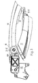
- das perspektivisch dargestellte erfindurigsgemäße Antriebsmittel für das vordere Dachteil in Ausgangslage,
- Fig. 5
- das Antriebsmittel gemäß Fig.4 in einer der Fig. 2 entsprechenden Zwischenlage und
- Fig. 6
- das Antriebsmittel gemäß Fig. 4 in einer der Fig. 3 entsprechenden Endlage.
- Fig. 1
- a convertible system according to the invention,
- Fig. 2
- the convertible system in half open position,
- Fig. 3
- the convertible system in open (stored) position,
- Figure 4
- the perspectively illustrated inventive drive means for the front roof part in the starting position,
- Fig. 5
- the drive means according to Figure 4 in one of the Fig. 2 corresponding intermediate layer and
- Fig. 6
- the drive means of FIG. 4 in one of FIG. 3 corresponding end position.
In Fig. 1 ist ein zwei starre Dachteile 10, 11 und ein Antriebsmittel 12 aufweisendes Cabriosystem 13 dargestellt, das an einer andeutungsweise erkennbaren Karosserie 14 um eine rechtwinklig zur Zeichenebene gerichtete Achse X-X an einem Hauptlager 15 schwenkbar gelagert ist. Das Hauptlager 15 ist an Stellen 16 mit der Fahrzeugkarosserie 14 verbunden, bspw. verschraubt, und trägt an einer mit Versteifungsrippen 17 versehenen Konsole 18 einen Flüssigkeitsantrieb 19 für das hintere Dachteil 11, das mit dem Flüssigkeitsantrieb 19 starr verbunden ist. Der Flüssigkeitsantrieb 19 wird wie das Antriebsmittel 12, das auch ein Flüssigkeitsantrieb ist, über Leitungen 20 von einer Steuereinheit 21 gesteuert. Das in den Figuren 4 bis 6 näher beschriebene Antriebsmittel 12 ist mit beiden Dachteilen 10, 11 fest verbunden und bewirkt die Schwenkung des Dachteils 10 um eine zur Achse X-X parallele Achse Y-Y gegenüber dem Dachteil 11. Der Flüssigkeitsantrieb 19 kann auch durch einen Elektroantrieb ersetzt werden. Auch in diesem Fall werden beide Antriebe 12 und 19 durch die Steuereinheit synchronisiert. In Fig. 1 sind noch Bewegungsmittel 22 für die im Übrigen nicht dargestellte Hutablage vorgesehen. Es versteht sich von selbst, dass das Hauptlager 15 und die Antriebsmittel 12, 19 beiderseits an einer Fahrzeugkarosserie 14 vorgesehen sind.
In Fig. 1 ist das Cabriosystem 13 in der Ausgangslage "Schließstellung" dargestellt. Fig. 2 zeigt ein teilweise geöffnetes Cabriosystem. Das hintere Dachteil 11 ist mit dem Flüssigkeitsantrieb 19 deutlich gegenüber der Ausgangslage verschwenkt. Gleichzeitig hat das vordere Dachteil 10 durch die bewegungskoordinierende Wirkung der nur in Fig. 1 dargestellten Steuereinheit 21 eine Schwenkung um die Achse Y-Y erfahren, durch die sich die vom Dachteil 11 abliegende Seite 101 des Dachteils 10 dem Dachteil 11 und der Schwenkachse X-X nähert. Das Cabriodach 10, 11 erfährt mit anderen Worten eine Knickung um die Achse Y-Y.
In Fig. 3 hat das Cabriosystem 13 die Endlage seines Bewegungsablaufs erreicht. Das Dachteil 10 befindet sich nach Knickung um die raumbewegliche Achse Y-Y in nahezu antiparalleler Lage zum Dachteil 11, das seinerseits um die Achse X-X eine Schwenkung erfahren hat, die zwischen 90° und 180° liegt. Dabei kommt die abliegende Seite 101 in die Nähe des Antriebs 19 zu liegen.In Fig. 1, a two
In Fig. 1, the
In Fig. 3, the
Die Figuren 4 bis 6 zeigen die Antriebsmittel 12 in zu den Dachteilen 10, 11 in den Figuren 1 bis 3 analogen Positionen. In Fig. 4 ist ein Fluidzylinder 121 mit einem verstellbaren Kolben 122 und Einlässen 123, 124 für eine Flüssigkeit oder ein Gas in die durch den Kolben 122 im Zylinder 121 gebildeten und veränderbaren Kammern 125, 126 versehen. Am Zylinder 121 ist eine Kulissenführung 127 fest angebracht, die in zwei parallel zueinander und zur geometrischen Achse Z-Z des Zylinders 121 verlaufenden Schenkeln 128, 129 Führungsschlitze 130, 131 für einen Führungskörper 132 aufweisen, der mit dem Kolben 122 bspw. über eine nicht sichtbare Stange in Verbindung steht. Mit dem Zylinder 121 bzw. mit der Kulissenführung 127 sind Laschen 133, 134 starr verbunden, mit denen das Antriebsmittel 12 am Dachteil 11 so befestigt wird, dass die Zylinderachse Z-Z im Wesentlichen in Bewegungsrichtung der Dachteile 10, 11 liegt. An und zwischen den Schenkeln 128, 129 ist um die raumbewegliche Achse Y-Y ein zweiarmiger Hebel 135 schwenkbar gelagert, der an seinem kürzeren Ende über ein aus zwei Schwingen 136 bestehendes Verbindungsstück mit dem Führungskörper 132 und der verdeckten Kolbenstange in Verbindung steht. Der Lagerung des zweiarmigen Hebels 135 zwischen den Schenkeln 128, 129 dient ein Lagerbolzen 137, der unterhalb der Führungsschlitze 130, 131 in die Schenkel 128, 129 eingeschraubt ist. Am längeren Ende ist der zweiarmige Hebel 135 mit dem Dachteil 10 starr verbunden. Die gesamte Anordnung ist in diesem Ausführungsbeispiel so getroffen, dass die Antriebsmittel 12 und die Dachteile 10, 11 eine gemeinsame Bewegungsebene haben.FIGS. 4 to 6 show the drive means 12 in positions analogous to the
Soll das Cabriodach geöffnet werden, so wird entsprechend der Funktion der Steuereinheit 21 von einem nicht dargestellten Reservoir ein Fluidum durch den Einlass 123 in die Kammer 125 gedrückt und damit der Kolben 122 im Zylinder 121 in Richtung des Einlasses 124 bewegt. Der Führungskörper 132 wird in Folge dessen in der Kulissenführung 127 zum anderen Führungsende hin bewegt und der mit seinem längeren Ende gegenüber der Achse Z-Z leicht geneigte Doppelhebel 135 über die Schwingen 136 um die Achse Y-Y in Richtung eines Pfeils 138 weiter gedreht. Damit ergibt sich eine Zwischenlage, wie sie bspw. aus Fig. 5 entnehmbar ist, in welcher der Führungskörper 132 in den Führungsschlitzen 130, 131 so verschoben ist, dass die Schwingen 136 das kürzere Ende des zweiarmigen Hebels 135 aus der Kulissenführung 127 heraus nach oben drücken und so den Hebel 135 um den Lagerbolzen 137 schwenken. Wenn der Kolben 122 im Zylinder 121 und der Führungskörper 132 in den Führungsschlitzen 130, 131 ihre in Fig. 6 erkennbaren Endlagen erreichen, sind die Schwingen 136 im Wesentlichen rechtwinklig und der Hebel 135 im Wesentlichen antiparallel zur Achse Z-Z gerichtet. Dieser Sachverhalt entspricht der Fig. 3, wobei allerdings zu beachten ist, dass synchron zur Schwenkung des Hebels 135 eine etwa gleich große, aber entgegengesetzte Schwenkung des Dachteils 11 um die Achse X-X stattfindet, an dem das Antriebsmittel 12 befestigt ist. Dadurch kommt das Dachteil 10 im Zustand der Ablage über das Dachteil 11 zu liegen.
Wird durch den Einlass 124 ein Fluidum in die Kammer 126 gedrückt, so findet der Bewegungsvorgang in umgekehrter Richtung und Reihenfolge statt bis sich die Dachteile 10, 11 in Schließstellung befinden.If the convertible roof is to be opened, a fluid is forced through the
If a fluid is pressed into the
Es versteht sich von selbst, dass die Erfindung nicht an die dargestellte Ausführungsform gebunden ist. So kann bspw. das Kolben-Zylinder-System nicht nur mit Hilfe einer Flüssigkeit oder eines Gases, sondern auch elektrisch betrieben werden. Dabei kann der Zylinder 121 am Dachteil 10 befestigt und der Kolben 122 mit dem Dachteil 11 verbunden sein. Auch kann bei entsprechender Anpassung der Antriebsmittel 12 der Zylinder 121 sich gegenüber dem Kolben 122 bewegen. Die Endstellungen des Bewegungsablaufs müssen nicht um 180° oder nahezu 180° auseinander liegen. Das Zwischenstück 136 muss nicht die Form zweier Schwingen aufweisen und die Kulissenführung 127 nicht zweischenklig sein, um nur einige abweichende Gestaltungsmöglichkeiten der Erfindung zu nennen.It goes without saying that the invention is not bound to the illustrated embodiment. Thus, for example, the piston-cylinder system can be operated not only by means of a liquid or a gas, but also electrically. In this case, the
- 10, 1110, 11
- Dachteileroof parts
- 1212
- Antriebsmitteldrive means
- 1313
- CabriosystemConvertible system
- 1414
- Karosseriebody
- 1515
- Hauptlagermain bearing
- 1616
- Stellen der VerbindungMake the connection
- 1717
- Versteifungsrippenstiffening ribs
- 1818
- Konsoleconsole
- 1919
- Flüssigkeitsantriebfluid drive
- 2020
- Leitungencables
- 2121
- Steuereinheitcontrol unit
- 2222
- Bewegungsmittelmeans
- 101101
- abliegende Seiteremote side
- 121121
- Fluidzylinderfluid cylinder
- 122122
- Kolbenpiston
- 123, 124123, 124
- Einlässeinlets
- 125, 126125, 126
- Kammernchambers
- 127127
- Kulissenführunglink guide
- 128, 129128, 129
- Schenkelleg
- 130, 131130, 131
- Führungsschlitzeguide slots
- 132132
- Führungskörperguide body
- 133, 134133, 134
- Laschentabs
- 135135
- Hebellever
- 136136
- SchwingenSwing
- 137137
- Lagerbolzenbearing bolt
- 138138
- Pfeilarrow
- X-X, Y-Y, Z-ZX-X, Y-Y, Z-Z
- Achsenaxes
Claims (7)
Applications Claiming Priority (1)
| Application Number | Priority Date | Filing Date | Title |
|---|---|---|---|
| DE102005061201A DE102005061201B3 (en) | 2005-12-19 | 2005-12-19 | Convertible system for e.g. cabriolet-vehicle, has support for lever and provided in guiding part, where lever is connected with rear roof part, and connecting strap between guiding body and lever is hinged to lever |
Publications (2)
| Publication Number | Publication Date |
|---|---|
| EP1798087A2 true EP1798087A2 (en) | 2007-06-20 |
| EP1798087A3 EP1798087A3 (en) | 2009-07-29 |
Family
ID=37846127
Family Applications (1)
| Application Number | Title | Priority Date | Filing Date |
|---|---|---|---|
| EP06025628A Withdrawn EP1798087A3 (en) | 2005-12-19 | 2006-12-12 | Cabriolet system with two rigid roof parts arranged one after another |
Country Status (3)
| Country | Link |
|---|---|
| US (1) | US20070138828A1 (en) |
| EP (1) | EP1798087A3 (en) |
| DE (1) | DE102005061201B3 (en) |
Families Citing this family (1)
| Publication number | Priority date | Publication date | Assignee | Title |
|---|---|---|---|---|
| US7959208B2 (en) * | 2008-12-22 | 2011-06-14 | Wilhelm Karmann Gmbh | Convertible top with in-folding side rails |
Citations (3)
| Publication number | Priority date | Publication date | Assignee | Title |
|---|---|---|---|---|
| EP0811518A1 (en) * | 1996-06-08 | 1997-12-10 | Wilhelm Karmann GmbH | Vehicle, particularly with foldable roof |
| DE10112092C1 (en) * | 2001-03-12 | 2002-08-08 | Cts Fahrzeug Dachsysteme Gmbh | Cabriolet vehicle roof adjustable between a closed position and an open position |
| DE102004035327B3 (en) * | 2004-07-21 | 2006-04-06 | Daimlerchrysler Ag | Hardtop cover for motor vehicle has toothed rod with drive connection to third pinion for pivoting rear screen relative to C-pillars |
Family Cites Families (6)
| Publication number | Priority date | Publication date | Assignee | Title |
|---|---|---|---|---|
| DE4438925C1 (en) * | 1994-10-31 | 1995-11-09 | Porsche Ag | Folding roof for motor vehicle |
| DE59604731D1 (en) * | 1995-06-22 | 2000-04-27 | Karmann Gmbh W | Folding top for a convertible vehicle |
| AT408735B (en) * | 2000-03-21 | 2002-02-25 | Hoerbiger Hydraulik | ACTUATING ARRANGEMENT FOR SWIVELING PARTS ON VEHICLES |
| AT408868B (en) * | 2000-05-31 | 2002-03-25 | Hoerbiger Hydraulik | OPERATING ARRANGEMENT FOR SWIVELING PARTS OF COVER |
| DE10111207A1 (en) * | 2001-03-08 | 2002-09-19 | Valmet Automotive Oy Uusikaupu | Convertible top |
| DE10140232A1 (en) * | 2001-08-22 | 2003-03-13 | Karmann Gmbh W | Cabriolet vehicle with a rigid rear roof section |
-
2005
- 2005-12-19 DE DE102005061201A patent/DE102005061201B3/en not_active Expired - Fee Related
-
2006
- 2006-12-12 EP EP06025628A patent/EP1798087A3/en not_active Withdrawn
- 2006-12-19 US US11/642,284 patent/US20070138828A1/en not_active Abandoned
Patent Citations (3)
| Publication number | Priority date | Publication date | Assignee | Title |
|---|---|---|---|---|
| EP0811518A1 (en) * | 1996-06-08 | 1997-12-10 | Wilhelm Karmann GmbH | Vehicle, particularly with foldable roof |
| DE10112092C1 (en) * | 2001-03-12 | 2002-08-08 | Cts Fahrzeug Dachsysteme Gmbh | Cabriolet vehicle roof adjustable between a closed position and an open position |
| DE102004035327B3 (en) * | 2004-07-21 | 2006-04-06 | Daimlerchrysler Ag | Hardtop cover for motor vehicle has toothed rod with drive connection to third pinion for pivoting rear screen relative to C-pillars |
Also Published As
| Publication number | Publication date |
|---|---|
| DE102005061201B3 (en) | 2007-04-05 |
| EP1798087A3 (en) | 2009-07-29 |
| US20070138828A1 (en) | 2007-06-21 |
Similar Documents
| Publication | Publication Date | Title |
|---|---|---|
| EP2008846B1 (en) | Sliding door for a vehicle | |
| DE102008016650B3 (en) | Sliding door for a vehicle | |
| EP1767388B1 (en) | Pivotable sliding vehicle door , especially for public transport | |
| DE102005005237B3 (en) | Arrangement for pivoting the parts of a vehicle hood | |
| DE102008026137B4 (en) | Sliding door for a vehicle | |
| EP0716004B1 (en) | Pivoting and sliding door for passenger-transporting vehicles | |
| EP3612701B1 (en) | Pivoting drive | |
| EP2365171A2 (en) | Storage of a hood on the structure of a motor vehicle and chassis for such a motor vehicle | |
| DE102008047046B4 (en) | Door drive for a pivoting sliding door of a vehicle | |
| DE102005061201B3 (en) | Convertible system for e.g. cabriolet-vehicle, has support for lever and provided in guiding part, where lever is connected with rear roof part, and connecting strap between guiding body and lever is hinged to lever | |
| EP1842709A2 (en) | Adjustable vehicle roof | |
| DE102007024570B4 (en) | Hinge for a motor vehicle door | |
| DE1605887C3 (en) | Joint arrangement for vehicle hoods | |
| DE102008004316A1 (en) | Motor vehicle i.e. cabriolet vehicle, has arms shifted to body for opening or closing cover part, and restricted guidance devices formed by connecting members to which holding unit is contacted | |
| DE202006001230U1 (en) | Motor vehicle e.g. van, door e.g. side door, has plate that is positively joined to holding frame through two handle bars according to type of four-joint linkage, where handle bars are arranged at distance from each other | |
| DE102013009921A1 (en) | Door drive for swinging-sliding door of e.g. omnibus, has lever assembly including two mutually articulated lever elements which are moved by drive device for securing door leaf in closed position into dead center or beyond dead center | |
| DE102005007728A1 (en) | Hard top | |
| DE102004035093B4 (en) | Hood for a convertible vehicle | |
| DE102006051804B3 (en) | Multi-flap drive for e.g. motor vehicle, has pivoting drive for pivoting of flaps around different pivoting axes, and linear drive provided for linearly moving one pivoting axis of one flap, where pivoting drive is coupled with linear drive | |
| DE10018732A1 (en) | Ejector device for a flap arrangement comprises a two-armed lever rotatably positioned on a flap and a housing in a plane perpendicular to the axis of rotation | |
| EP1798090B1 (en) | Rear shelf for cabriolet | |
| AT520902B1 (en) | Cross spindle drive with locking device for sliding doors and pivoting sliding doors for rail vehicles for passenger transport | |
| DE102010055047B4 (en) | Movable and lockable roof part of a vehicle roof | |
| DE102005050897B3 (en) | Hard top vehicle-roof has roof part which is hinged to boot lid in closing position of roof and is hinged to rotation handle bar by relative kinematics | |
| DE102006022822B3 (en) | Drive for the roof mechanism of a convertible automobile, with at least two rigid roof sections, releases the locks before the roof opening movements |
Legal Events
| Date | Code | Title | Description |
|---|---|---|---|
| PUAI | Public reference made under article 153(3) epc to a published international application that has entered the european phase |
Free format text: ORIGINAL CODE: 0009012 |
|
| AK | Designated contracting states |
Kind code of ref document: A2 Designated state(s): AT BE BG CH CY CZ DE DK EE ES FI FR GB GR HU IE IS IT LI LT LU LV MC NL PL PT RO SE SI SK TR |
|
| AX | Request for extension of the european patent |
Extension state: AL BA HR MK YU |
|
| PUAL | Search report despatched |
Free format text: ORIGINAL CODE: 0009013 |
|
| AK | Designated contracting states |
Kind code of ref document: A3 Designated state(s): AT BE BG CH CY CZ DE DK EE ES FI FR GB GR HU IE IS IT LI LT LU LV MC NL PL PT RO SE SI SK TR |
|
| AX | Request for extension of the european patent |
Extension state: AL BA HR MK RS |
|
| STAA | Information on the status of an ep patent application or granted ep patent |
Free format text: STATUS: THE APPLICATION IS DEEMED TO BE WITHDRAWN |
|
| 18D | Application deemed to be withdrawn |
Effective date: 20090701 |