EP2365171A2 - Storage of a hood on the structure of a motor vehicle and chassis for such a motor vehicle - Google Patents
Storage of a hood on the structure of a motor vehicle and chassis for such a motor vehicle Download PDFInfo
- Publication number
- EP2365171A2 EP2365171A2 EP11001161A EP11001161A EP2365171A2 EP 2365171 A2 EP2365171 A2 EP 2365171A2 EP 11001161 A EP11001161 A EP 11001161A EP 11001161 A EP11001161 A EP 11001161A EP 2365171 A2 EP2365171 A2 EP 2365171A2
- Authority
- EP
- European Patent Office
- Prior art keywords
- flap
- actuator
- motor vehicle
- adjusting device
- bearing
- Prior art date
- Legal status (The legal status is an assumption and is not a legal conclusion. Google has not performed a legal analysis and makes no representation as to the accuracy of the status listed.)
- Withdrawn
Links
Images


Classifications
-
- E—FIXED CONSTRUCTIONS
- E05—LOCKS; KEYS; WINDOW OR DOOR FITTINGS; SAFES
- E05D—HINGES OR SUSPENSION DEVICES FOR DOORS, WINDOWS OR WINGS
- E05D15/00—Suspension arrangements for wings
- E05D15/40—Suspension arrangements for wings supported on arms movable in vertical planes
- E05D15/46—Suspension arrangements for wings supported on arms movable in vertical planes with two pairs of pivoted arms
-
- B—PERFORMING OPERATIONS; TRANSPORTING
- B60—VEHICLES IN GENERAL
- B60J—WINDOWS, WINDSCREENS, NON-FIXED ROOFS, DOORS, OR SIMILAR DEVICES FOR VEHICLES; REMOVABLE EXTERNAL PROTECTIVE COVERINGS SPECIALLY ADAPTED FOR VEHICLES
- B60J5/00—Doors
- B60J5/04—Doors arranged at the vehicle sides
- B60J5/0486—Special type
- B60J5/0491—Special type lid, e.g. for luggage compartment accessible at vehicle side
-
- E—FIXED CONSTRUCTIONS
- E05—LOCKS; KEYS; WINDOW OR DOOR FITTINGS; SAFES
- E05F—DEVICES FOR MOVING WINGS INTO OPEN OR CLOSED POSITION; CHECKS FOR WINGS; WING FITTINGS NOT OTHERWISE PROVIDED FOR, CONCERNED WITH THE FUNCTIONING OF THE WING
- E05F15/00—Power-operated mechanisms for wings
- E05F15/50—Power-operated mechanisms for wings using fluid-pressure actuators
- E05F15/53—Power-operated mechanisms for wings using fluid-pressure actuators for swinging wings
-
- E—FIXED CONSTRUCTIONS
- E05—LOCKS; KEYS; WINDOW OR DOOR FITTINGS; SAFES
- E05Y—INDEXING SCHEME RELATING TO HINGES OR OTHER SUSPENSION DEVICES FOR DOORS, WINDOWS OR WINGS AND DEVICES FOR MOVING WINGS INTO OPEN OR CLOSED POSITION, CHECKS FOR WINGS AND WING FITTINGS NOT OTHERWISE PROVIDED FOR, CONCERNED WITH THE FUNCTIONING OF THE WING
- E05Y2201/00—Constructional elements; Accessories therefore
- E05Y2201/40—Motors; Magnets; Springs; Weights; Accessories therefore
- E05Y2201/43—Motors
- E05Y2201/448—Fluid motors; Details thereof
-
- E—FIXED CONSTRUCTIONS
- E05—LOCKS; KEYS; WINDOW OR DOOR FITTINGS; SAFES
- E05Y—INDEXING SCHEME RELATING TO HINGES OR OTHER SUSPENSION DEVICES FOR DOORS, WINDOWS OR WINGS AND DEVICES FOR MOVING WINGS INTO OPEN OR CLOSED POSITION, CHECKS FOR WINGS AND WING FITTINGS NOT OTHERWISE PROVIDED FOR, CONCERNED WITH THE FUNCTIONING OF THE WING
- E05Y2600/00—Mounting or coupling arrangements for elements provided for in this subclass
- E05Y2600/40—Mounting location; Visibility of the elements
- E05Y2600/46—Mounting location; Visibility of the elements in or on the wing
-
- E—FIXED CONSTRUCTIONS
- E05—LOCKS; KEYS; WINDOW OR DOOR FITTINGS; SAFES
- E05Y—INDEXING SCHEME RELATING TO HINGES OR OTHER SUSPENSION DEVICES FOR DOORS, WINDOWS OR WINGS AND DEVICES FOR MOVING WINGS INTO OPEN OR CLOSED POSITION, CHECKS FOR WINGS AND WING FITTINGS NOT OTHERWISE PROVIDED FOR, CONCERNED WITH THE FUNCTIONING OF THE WING
- E05Y2900/00—Application of doors, windows, wings or fittings thereof
- E05Y2900/50—Application of doors, windows, wings or fittings thereof for vehicles
- E05Y2900/506—Application of doors, windows, wings or fittings thereof for vehicles for buses
-
- E—FIXED CONSTRUCTIONS
- E05—LOCKS; KEYS; WINDOW OR DOOR FITTINGS; SAFES
- E05Y—INDEXING SCHEME RELATING TO HINGES OR OTHER SUSPENSION DEVICES FOR DOORS, WINDOWS OR WINGS AND DEVICES FOR MOVING WINGS INTO OPEN OR CLOSED POSITION, CHECKS FOR WINGS AND WING FITTINGS NOT OTHERWISE PROVIDED FOR, CONCERNED WITH THE FUNCTIONING OF THE WING
- E05Y2900/00—Application of doors, windows, wings or fittings thereof
- E05Y2900/50—Application of doors, windows, wings or fittings thereof for vehicles
- E05Y2900/51—Application of doors, windows, wings or fittings thereof for vehicles for railway cars or mass transit vehicles
-
- E—FIXED CONSTRUCTIONS
- E05—LOCKS; KEYS; WINDOW OR DOOR FITTINGS; SAFES
- E05Y—INDEXING SCHEME RELATING TO HINGES OR OTHER SUSPENSION DEVICES FOR DOORS, WINDOWS OR WINGS AND DEVICES FOR MOVING WINGS INTO OPEN OR CLOSED POSITION, CHECKS FOR WINGS AND WING FITTINGS NOT OTHERWISE PROVIDED FOR, CONCERNED WITH THE FUNCTIONING OF THE WING
- E05Y2900/00—Application of doors, windows, wings or fittings thereof
- E05Y2900/50—Application of doors, windows, wings or fittings thereof for vehicles
- E05Y2900/53—Application of doors, windows, wings or fittings thereof for vehicles characterised by the type of wing
- E05Y2900/536—Hoods
-
- E—FIXED CONSTRUCTIONS
- E05—LOCKS; KEYS; WINDOW OR DOOR FITTINGS; SAFES
- E05Y—INDEXING SCHEME RELATING TO HINGES OR OTHER SUSPENSION DEVICES FOR DOORS, WINDOWS OR WINGS AND DEVICES FOR MOVING WINGS INTO OPEN OR CLOSED POSITION, CHECKS FOR WINGS AND WING FITTINGS NOT OTHERWISE PROVIDED FOR, CONCERNED WITH THE FUNCTIONING OF THE WING
- E05Y2900/00—Application of doors, windows, wings or fittings thereof
- E05Y2900/50—Application of doors, windows, wings or fittings thereof for vehicles
- E05Y2900/53—Application of doors, windows, wings or fittings thereof for vehicles characterised by the type of wing
- E05Y2900/54—Luggage compartment lids for buses
Definitions
- the invention relates to a bearing of a flap on a structure of a motor vehicle specified in the preamble of claim 1 species and a body for such a motor vehicle with the features of claim 5.
- FIG. 1A shows a lifting flap 10, which via a four-bar adjusting device 12 manually between a closing position an opening, which in the Fig. 1A is shown, and at least one opening releasing the open positions, which in the Fig. 1B is shown, is adjustable.
- the lifting flap 10 is pivotally connected to a support arm 14, which in turn is fastened via a bracket 16 about a pivot axis pivotally mounted on the structure of the coach, not shown.
- the lift flap 10 is pivotally connected to a guide arm 18 which is also pivotally connected to said structure pivotally about a pivot axis.
- the guide arm 18 serves to stabilize the lifting flap 10 so that it does not pivot uncontrollably about the articulated connection with the support arm 14.
- a gas spring 22 is provided, on the one hand on the guide arm 18 and on the other hand on a frame member 24 of the construction of the Coach is pivotally supported about respective pivot axes.
- the adjusting device 12 may include a linear motor 26, by means of which the lifting flap 10 can be moved from its closed position to its open position, without causing a person to raise its own force to open the lifting flap 10.
- a connecting tube 28 is provided, which connects the support arms 14 with each other, which is the Fig. 3 can be clearly seen.
- the actuator of the adjusting device allows a particularly simple adjustment of the flap from its closed position in the at least one open position and vice versa, without a person, such as a driver of the motor vehicle, has to apply its own strength. Rather, the adjustment of the flap can be automatic and thus particularly comfortable, for example by pressing a button or flipping a lever or the like done.
- the storage according to the invention has low costs, as by the relative to the flap fixed support of the actuator and its co-movement in the adjustment a simple integration of this automatically actuated flap in the car without changing the structure and / or any frame for holding the flap is possible.
- Existing, inexpensive and manually operable flaps are exchangeable by the storage according to the invention in a simple and cost-effective manner by automatically, ie by external force, operable flap of the storage according to the invention, without modification to the existing cars, its structure, any frame or the like to make have to. This is accompanied by the maintenance of a very large volume, for example a storage space, which can be opened or closed by the flap of the storage according to the invention.
- the storage according to the invention is independent of tolerances of the structure, for example, the shell, the motor vehicle, since the actuator integrated into the flap and thus an additional, tolerance-sensitive interface between actuator and structure is avoided.
- the actuator is designed as a rotary drive.
- the actuator generates a torque and a rotational movement, wherein the torque is on the flap side of the structure or possibly on a support frame of the motor vehicle, on which the flap is to be transmitted.
- the support of the torque takes place on the flap instead of the construction or the shell of the motor vehicle.
- a force or momentary effect of the rotary drive does not need to be converted via levers and certain kinematics into a rotary motion to show a pivot about a pivot axis of the flap, whereby the adjustment of the flap between its open position and its closed position particularly energy efficient and thus without particularly large and unwanted losses feasible.
- the actuator is held by a strut assembly on the flap, which has the advantage that thereby a particularly large-scale support of the force of the actuator is realized on the flap.
- This avoids a selective introduction of force and thus a particularly high relative to a surface Force application, which ensures a long life and a very good reliability over this long life of storage according to the invention.
- the holder and thus the support of the actuator on the flap can also be done via defined connection points, which are spaced apart by the strut assembly by a certain distance from each other to represent a particularly advantageous and uniform force in the flap.
- the invention also relates to a bodywork for a motor vehicle, in particular a touring coach, with at least one bearing according to the invention, wherein in one embodiment by means of the actuator at least one rotationally fixed to the actuator torsion bar of the adjusting device is rotatable, which at least one at least substantially oblique, in particular perpendicular to the pivot rod extending pivot arm of the actuating device is rotatably connected, wherein the pivot arm is pivotally mounted about a pivot axis of the structure.
- the flap on the actuator, the torsion bar and the swivel arm is held on the structure, particularly easy to adjust and cost integrated into the car.
- the torsion bar is rotatably supported on the flap, which is accompanied by an improved introduction of force and support of the actuator in or on the flap.
- FIGS. 1 to 3 Lifting flaps for coaches according to the prior art show that shows Fig. 4 a storage of such a lifting flap, which allows easy operation and a very cost-effective integration of this in a coach.
- the Fig. 4 shows a storage 32 of a lifting flap 10 'on a structure 34 of a coach, the structure 34 in the vehicle vertical direction according to a directional arrow 35 extending frame members 36 and 38 and in the vehicle longitudinal direction according to a direction arrow 48 extending frame members 42 and 44 includes.
- the frame members 36, 38, 42 and 44 define an opening 46, via which a storage space of the coach for accommodating luggage or the like is accessible.
- an adjusting device 12 ' is provided, the pivot arms 48, guide arms 18' and torsion bars 50 and gas springs 22 'includes. Furthermore, the adjusting device 12 'comprises an actuator in the form of a pneumatically actuated rotary drive 52, by means of which the lifting flap 10' between a closing the opening 46 and in the Fig. 4 shown closed position and at least one opening 46 releasing open position is adjustable.
- the rotary drive 52 is held relative to the lifting flap 10 'fixed to this and mitbewegbar in an adjustment of this between the closed position and the open position.
- the rotary drive 52 generates a rotational movement and a torque, which is on the flap side on the adjusting device 12 'is transmitted.
- a forced kinematics represented by the adjusting device 12 ' causes a rotation of the torsion bars 50 by the rotational movement of the actuator 52, an opening or closing the lift valve 10.
- the pivot arms 48 on the one hand via respective brackets 54 on the structure 34 to a respective parallel to vehicle longitudinal direction pivotally held according to the direction of arrow 40 pivot axis.
- the pivot arms 48 are rotatably connected to one of the torsion bars 50, wherein they are perpendicular to the torsion bars 50.
- the torsion bars 50 in turn are rotatably supported by respective brackets 56 on the lift flap 10 ', whereby a defined and safe opening of the flap is realized.
- the guide arms 18 ' are provided, which are pivotally supported on the one hand pivotally about a pivot axis on the frame members 38 and on the other hand about a pivot axis on the lifting flap 10'.
- Gas springs 22 ' serve the purpose of assisting an adjustment of the lift flap 10' between its open position and its closed position in order to allow the use of a smaller sized and possibly less powerful rotary drive 52, which keeps the cost of the storage 32 in a small frame.
- the rotary drive 52 is held by a strut assembly 58 on the lift valve 10 'and supported on this, resulting in a two-dimensional force or torque input from the rotary actuator 52 results on the lift valve 10'.
- the strut assembly 58 includes for this purpose Blechkantmaschine 60 and 62.
- Blechkantmaschine 60 and 62 To create a certain stability of the lift flap 10 ', which is designed as a sheet metal flap, it has a rib structure 60, wherein ribs of the rib structure 60 have a trapezoidal cross-section. Representing this, such a rib 62 is mentioned, which has a cutout in the region of the rotary drive 52 in order to integrate the rotary drive 52 into the lift flap 10 'at least virtually without space.
- the storage 32 is thus a solution that can be easily and inexpensively integrated into the coach without having to make changes to the shell, which includes, for example, the structure 34 with the frame members 36, 38, 42 and 44, at simultaneous realization of an automatic actuation of the flap, without a person such as a driver of the coach would have to apply its own force for adjusting the lifting flap 10 '.
Abstract
Description
Die Erfindung betrifft eine Lagerung einer Klappe an einem Aufbau eines Kraftwagens der im Oberbegriff des Patentanspruchs 1 angegebenen Art sowie eine Karosserie für einen solchen Kraftwagen mit den Merkmalen des Patentanspruchs 5.The invention relates to a bearing of a flap on a structure of a motor vehicle specified in the preamble of claim 1 species and a body for such a motor vehicle with the features of claim 5.
Derartige Lagerungen von Klappen an einem Aufbau eines Kraftwagens, insbesondere eines Reisebusses, sind hinlänglich bekannt und in den
Zur Unterstützung der Verstellung der Hubklappe 10 von der Schließstellung in die Offenstellung, wobei die Hubklappe 10 gemäß einem Richtungspfeil 20 in Fahrzeughochrichtung nach oben verstellt wird, ist eine Gasfeder 22 vorgesehen, die einerseits an dem Führungsarm 18 und andererseits an einem Rahmenelement 24 des Aufbaus des Reisebusses um jeweilige Schwenkachsen schwenkbar abgestützt ist.To assist the adjustment of the
Aus dem Serienkraftwagenbau weiterhin bekannt und in der
Die aus dem Serienkraftwagenbau bekannten Hubklappe 10 weist dabei den Nachteil auf, dass zur Integration der Hubklappe 10 mit dem Linearmotor 26 ein großer Aufwand betrieben werden muss, welcher eine Änderung des Aufbaus sowie der Klappe 10 selbst gegenüber der manuell zu betätigenden Klappe 10 gemäß den
Es ist daher Aufgabe der vorliegenden Erfindung, eine Lagerung einer Klappe an einem Aufbau eines Kraftwagens sowie eine Karosserie für einen Kraftwagen bereitzustellen, welche eine einfache Betätigung der Klappe ermöglichen sowie geringe Kosten aufweisen.It is therefore an object of the present invention to provide a storage of a flap on a body of a motor vehicle and a body for a motor vehicle, which allow easy operation of the flap and have low costs.
Diese Aufgabe wird durch eine Lagerung einer Klappe an einem Aufbau eines Kraftwagens mit den Merkmalen des Patentanspruchs 1 sowie durch eine Karosserie für einen Kraftwagen mit den Merkmalen des Patentanspruchs 5 gelöst. Vorteilhafte Ausgestaltungen mit zweckmäßigen und nicht-trivialen Weiterbildungen der Erfindung sind in den abhängigen Ansprüchen angegeben.This object is achieved by a storage of a flap on a structure of a motor vehicle with the features of claim 1 and by a body for a motor vehicle with the features of claim 5. Advantageous embodiments with expedient and non-trivial developments of the invention are specified in the dependent claims.
Eine erfindungsgemäße Lagerung einer Klappe, Tür oder dergleichen Flügelelements an einem Aufbau eines Kraftwagens, insbesondere eines Reisebusses, bei welcher wenigstens eine Stelleinrichtung mit wenigstens einem Stellantrieb vorgesehen ist, mittels welchem die Klappe oder dergleichen zwischen einer eine Öffnung verschließenden Schließstellung zumindest einer die Öffnung zumindest bereichsweise freigebenden Offenstellung verstellbar ist, zeichnet sich dadurch aus, dass der Stellantrieb der Stelleinrichtung an der Klappe oder dergleichen fest gehalten und bei einer Verstellung zwischen der Schließstellung und der Offenstellung mitbewegbar ist.A storage according to the invention of a flap, door or similar wing element on a construction of a motor vehicle, in particular a coach, in which at least one adjusting device is provided with at least one actuator, by means of which the flap or the like between a closing position closing an opening at least one opening at least partially releasing open position is adjustable, characterized in that the actuator of the actuating device on the flap or the like held firm and mitbewegbar in an adjustment between the closed position and the open position.
Der Stellantrieb der Stelleinrichtung ermöglicht eine besonders einfache Verstellung der Klappe von deren Schließstellung in deren zumindest eine Offenstellung und umgekehrt, ohne dass eine Person, wie beispielsweise ein Fahrer des Kraftwagens, eigene Kraft aufbringen muss. Vielmehr kann die Verstellung der Klappe automatisch und damit besonders komfortabel, beispielsweise durch Drücken eines Knopfes oder Umlegen eines Hebels oder dergleichen, erfolgen.The actuator of the adjusting device allows a particularly simple adjustment of the flap from its closed position in the at least one open position and vice versa, without a person, such as a driver of the motor vehicle, has to apply its own strength. Rather, the adjustment of the flap can be automatic and thus particularly comfortable, for example by pressing a button or flipping a lever or the like done.
Darüber hinaus weist die erfindungsgemäße Lagerung geringe Kosten auf, da durch die relativ zu der Klappe feste Halterung des Stellantriebs und dessen Mitbewegung bei der Verstellung eine einfache Integration dieser automatisch betätigbaren Klappe in den Kraftwagen ohne Änderungen des Aufbaus und/oder etwaiger Rahmen zur Halterung der Klappe möglich ist. Bereits bestehende, kostengünstige und manuell betätigbare Klappen sind dabei durch die erfindungsgemäße Lagerung in einfacher und kostengünstiger Weise durch die automatisch, also mittels Fremdkraft, betätigbare Klappe der erfindungsgemäßen Lagerung austauschbar, ohne Änderung an dem bestehenden Kraftwagen, dessen Aufbau, etwaiger Rahmen oder dergleichen vornehmen zu müssen. Damit einher geht die Beibehaltung eines sehr großen Volumens beispielsweise eines Stauraums, welcher durch die Klappe der erfindungsgemäßen Lagerung freigebbar bzw. verschließbar ist. Weiterhin ist die erfindungsgemäße Lagerung unabhängig von Toleranzen des Aufbaus, beispielsweise des Rohbaus, des Kraftwagens, da der Stellantrieb in die Klappe integriert und damit eine zusätzliche, toleranzempfindliche Schnittstelle zwischen Stellantrieb und Aufbau vermieden ist.In addition, the storage according to the invention has low costs, as by the relative to the flap fixed support of the actuator and its co-movement in the adjustment a simple integration of this automatically actuated flap in the car without changing the structure and / or any frame for holding the flap is possible. Existing, inexpensive and manually operable flaps are exchangeable by the storage according to the invention in a simple and cost-effective manner by automatically, ie by external force, operable flap of the storage according to the invention, without modification to the existing cars, its structure, any frame or the like to make have to. This is accompanied by the maintenance of a very large volume, for example a storage space, which can be opened or closed by the flap of the storage according to the invention. Furthermore, the storage according to the invention is independent of tolerances of the structure, for example, the shell, the motor vehicle, since the actuator integrated into the flap and thus an additional, tolerance-sensitive interface between actuator and structure is avoided.
Bei einer besonders vorteilhaften Ausführungsform der Erfindung ist der Stellantrieb als Drehantrieb ausgebildet. In diesem Falle erzeugt also der Stellantrieb ein Drehmoment und eine Drehbewegung, wobei das Drehmoment klappenseitig auf den Aufbau oder ggf. auf ein Traggestell des Kraftwagens, an welchem die Klappe zu halten ist, übertragen wird. Somit erfolgt die Abstützung des Drehmoments auf der Klappe anstatt am Aufbau oder am Rohbau des Kraftwagens.In a particularly advantageous embodiment of the invention, the actuator is designed as a rotary drive. In this case, therefore, the actuator generates a torque and a rotational movement, wherein the torque is on the flap side of the structure or possibly on a support frame of the motor vehicle, on which the flap is to be transmitted. Thus, the support of the torque takes place on the flap instead of the construction or the shell of the motor vehicle.
Ein weiterer Vorteil des Drehantriebs ist, dass eine Kraft- bzw. Momentenwirkung des Drehantriebs nicht über Hebel und bestimmte Kinematiken in eine Rotationsbewegung zur Darstellung eines Verschwenkens um eine Schwenkachse der Klappe umgewandelt werden muss, wodurch die Verstellung der Klappe zwischen ihrer Offenstellung und ihrer Schließstellung besonders energieeffizient und somit ohne besonders große und unerwünschte Verluste durchführbar ist.Another advantage of the rotary drive is that a force or momentary effect of the rotary drive does not need to be converted via levers and certain kinematics into a rotary motion to show a pivot about a pivot axis of the flap, whereby the adjustment of the flap between its open position and its closed position particularly energy efficient and thus without particularly large and unwanted losses feasible.
Vorteilhafterweise ist der Stellantrieb über eine Strebenanordnung an der Klappe gehalten, was den Vorteil birgt, dass dadurch eine besonders großflächige Abstützung der Krafteinwirkung des Stellantriebs auf die Klappe realisiert ist. Dies vermeidet eine punktuelle Krafteinleitung und damit eine bezogen auf eine Fläche besonders hohe Krafteinleitung, was eine hohe Lebensdauer und eine sehr gute Funktionssicherheit über diese hohe Lebensdauer der erfindungsgemäßen Lagerung gewährleistet. Die Halterung und damit die Abstützung des Stellantriebs an der Klappe kann dabei auch über definierte Anbindungspunkte erfolgen, die durch die Strebenanordnung um einen gewissen Abstand voneinander beabstandet sind zur Darstellung einer besonders vorteilhaften und gleichmäßigen Krafteinleitung in die Klappe.Advantageously, the actuator is held by a strut assembly on the flap, which has the advantage that thereby a particularly large-scale support of the force of the actuator is realized on the flap. This avoids a selective introduction of force and thus a particularly high relative to a surface Force application, which ensures a long life and a very good reliability over this long life of storage according to the invention. The holder and thus the support of the actuator on the flap can also be done via defined connection points, which are spaced apart by the strut assembly by a certain distance from each other to represent a particularly advantageous and uniform force in the flap.
Die Erfindung betrifft auch eine Karosserie für einen Kraftwagen, insbesondere einen Reisebus, mit zumindest einer erfindungsgemäßen Lagerung, wobei bei einer Ausführungsform mittels des Stellantriebs zumindest ein mit dem Stellantrieb drehfest verbundener Drehstab der Stelleinrichtung drehbar ist, welcher mit zumindest einem zumindest im Wesentlichen schräg, insbesondere senkrecht, zu dem Drehstab verlaufenden Schwenkarm der Stelleinrichtung drehfest verbunden ist, wobei der Schwenkarm um eine Schwenkachse schwenkbar an dem Aufbau gehalten ist. Damit ist die Klappe über den Stellantrieb, den Drehstab und den Schwenkarm an dem Aufbau gehalten, besonders einfach verstellbar und kostengünstig in den Kraftwagen integrierbar. Vorteilhafterweise ist auch der Drehstab drehbar an der Klappe abgestützt, was mit einer verbesserten Krafteinleitung und Abstützung des Stellantriebs in bzw. an der Klappe einhergeht.The invention also relates to a bodywork for a motor vehicle, in particular a touring coach, with at least one bearing according to the invention, wherein in one embodiment by means of the actuator at least one rotationally fixed to the actuator torsion bar of the adjusting device is rotatable, which at least one at least substantially oblique, in particular perpendicular to the pivot rod extending pivot arm of the actuating device is rotatably connected, wherein the pivot arm is pivotally mounted about a pivot axis of the structure. Thus, the flap on the actuator, the torsion bar and the swivel arm is held on the structure, particularly easy to adjust and cost integrated into the car. Advantageously, the torsion bar is rotatably supported on the flap, which is accompanied by an improved introduction of force and support of the actuator in or on the flap.
Weitere Vorteile, Merkmale und Einzelheiten der Erfindung ergeben sich aus der nachfolgenden Beschreibung eines bevorzugten Ausführungsbeispiels sowie anhand der Zeichnungen. Die vorstehend in der Beschreibung genannten Merkmale und Merkmalskombinationen sowie die nachfolgend in der Figurenbeschreibung genannten und/oder in den Figuren alleine gezeigten Merkmale und Merkmalskombinationen sind nicht nur in der jeweils angegebenen Kombination, sondern auch in anderen Kombinationen oder in Alleinstellung verwendbar, ohne den Rahmen der Erfindung zu verlassen.Further advantages, features and details of the invention will become apparent from the following description of a preferred embodiment and from the drawings. The features and feature combinations mentioned above in the description as well as the features and feature combinations mentioned below in the description of the figures and / or in the figures alone can be used not only in the respectively specified combination but also in other combinations or in isolation, without the scope of To leave invention.
Die Zeichnungen zeigen in:
- Fig. 1A
- eine Seitenansicht einer Hubklappe für einen Reisebus gemäß dem Stand der Technik in einer Schließstellung;
- Fig. 1 B
- eine Seitenansicht der Hubklappe gemäß
Fig. 1A in einer Offenstellung; - Fig. 2
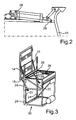
- eine perspektivische Ansicht eines Linearmotors zum Betätigen einer weiteren Ausführungsform einer Hubklappe für einen Reisebus gemäß dem Stand der Technik;
- Fig. 3
- eine perspektivische Ansicht der mittels des Linearmotors gemäß
Fig. 2 betätigbaren Hubklappe in einer Offenstellung; - Fig. 4
- eine perspektivische Ansicht einer Ausführungsform der erfindungsgemäßen Lagerung.
- Fig. 1A
- a side view of a lift flap for a coach according to the prior art in a closed position;
- Fig. 1 B
- a side view of the lifting flap according to
Fig. 1A in an open position; - Fig. 2
- a perspective view of a linear motor for actuating a further embodiment of a lift flap for a coach according to the prior art;
- Fig. 3
- a perspective view of the means of the linear motor according to
Fig. 2 actuatable lifting flap in an open position; - Fig. 4
- a perspective view of an embodiment of the storage according to the invention.
Während die
Die
Bei der Lagerung 32 ist eine Stelleinrichtung 12' vorgesehen, die Schwenkarme 48, Führungsarme 18' sowie Drehstäbe 50 und Gasfedern 22' umfasst. Des Weiteren umfasst die Stelleinrichtung 12' einen Stellantrieb in Form eines pneumatisch betätigbaren Drehantriebs 52, mittels welchem die Hubklappe 10' zwischen einer die Öffnung 46 verschließenden und in der
Wie der
Zur Ergänzung der Stelleinrichtung 12' zu einer viergelenkigen Stelleinrichtung 12' sind die Führungsarme 18' vorgesehen, die einerseits schwenkbar um eine Schwenkachse an den Rahmenelementen 38 und andererseits schwenkbar um eine Schwenkachse an der Hubklappe 10' gehalten und abgestützt sind.To supplement the adjusting device 12 'to a four-joint adjusting device 12', the guide arms 18 'are provided, which are pivotally supported on the one hand pivotally about a pivot axis on the
Gasfedern 22' dienen dem Zweck, eine Verstellung der Hubklappe 10' zwischen ihrer Offenstellung und ihrer Schließstellung zu unterstützen, um damit den Einsatz eines kleiner dimensionierten und ggf. leistungsschwächeren Drehantriebs 52 zu ermöglichen, was die Kosten der Lagerung 32 in einem geringen Rahmen hält.Gas springs 22 'serve the purpose of assisting an adjustment of the lift flap 10' between its open position and its closed position in order to allow the use of a smaller sized and possibly less powerful
Wie der
Bei der Lagerung 32 handelt es sich somit um eine Lösung, die einfach und kostengünstig in den Reisebus integriert werden kann, ohne Änderungen an dessen Rohbau, welcher beispielsweise den Aufbau 34 mit den Rahmenelementen 36, 38, 42 und 44 umfasst, durchführen zu müssen bei gleichzeitiger Realisierung einer automatischen Betätigung der Klappe, ohne dass eine Person wie beispielsweise ein Fahrer des Reisebusses eigene Kraft zum Verstellen der Hubklappe 10' aufbringen müsste.In the
Claims (8)
dadurch gekennzeichnet, dass
der Stellantrieb (52) der Stelleinrichtung (12') an der Klappe (10') oder dgl. fest gehalten und bei einer Verstellung zwischen der Schließstellung und der Offenstellung mitbewegbar ist.Bearing (32) of a flap (10 '), door or the like wing element on a structure (34) of a motor vehicle, in particular a coach, wherein at least one adjusting device (12') is provided with at least one actuator (52) by means of which the flap (10 ') or the like between an opening (46) closing a closed position and at least one opening (46) at least partially releasing open position is adjustable,
characterized in that
the actuator (52) of the actuating device (12 ') on the flap (10') or the like. Fixed and is mitbewegbar in an adjustment between the closed position and the open position.
dadurch gekennzeichnet, dass
der Stellantrieb (52) als Drehantrieb (52) ausgebildet ist.Bearing (32) according to claim 1,
characterized in that
the actuator (52) is designed as a rotary drive (52).
dadurch gekennzeichnet, dass
der Drehantrieb (52) als pneumatischer Drehantrieb (52) ausgebildet ist.Bearing (32) according to claim 2,
characterized in that
the rotary drive (52) is designed as a pneumatic rotary drive (52).
dadurch gekennzeichnet, dass
der Stellantrieb (52) über eine Strebenanordnung (58) an der Klappe (10') gehalten ist.Bearing (32) according to one of the preceding claims,
characterized in that
the actuator (52) via a strut assembly (58) on the flap (10 ') is held.
dadurch gekennzeichnet, dass
mittels des Stellantriebs (52) zumindest ein mit dem Stellantrieb (52) drehfest verbundener Drehstab (50) der Stelleinrichtung (12') drehbar ist, welcher mit zumindest einem zumindest im Wesentlichen schräg, insbesondere senkrecht, zu dem Drehstab (50) verlaufenden Schwenkarm (48) der Stelleinrichtung (12') drehfest verbunden ist, wobei der Schwenkarm (48) um eine Schwenkachse schwenkbar an dem Aufbau gehalten ist.Body according to claim 5,
characterized in that
by means of the actuator (52) at least one with the actuator (52) rotatably connected torsion bar (50) of the adjusting device (12 ') is rotatable, which at least one at least substantially obliquely, in particular perpendicular, to the torsion bar (50) extending arm ( 48) of the adjusting device (12 ') is rotatably connected, wherein the pivot arm (48) is pivotally supported about a pivot axis to the structure.
dadurch gekennzeichnet, dass
die Stelleinrichtung (12') als viergelenkige Stelleinrichtung (12') ausgebildet ist.Body according to one of claims 5 or 6,
characterized in that
the adjusting device (12 ') is designed as a four-joint adjusting device (12').
dadurch gekennzeichnet, dass
zumindest eine Federeinrichtung (22'), insbesondere eine Gasfeder (22'), vorgesehen ist, mittels welcher ein Verstellen der Klappe (10') unterstützbar ist.Body according to one of claims 5 to 7,
characterized in that
at least one spring device (22 '), in particular a gas spring (22'), is provided, by means of which an adjustment of the flap (10 ') can be supported.
Applications Claiming Priority (1)
| Application Number | Priority Date | Filing Date | Title |
|---|---|---|---|
| DE201010011094 DE102010011094A1 (en) | 2010-03-11 | 2010-03-11 | Support for use in lifting flap e.g. door, at body of overland bus, has adjusting device with adjusting drive that is fixedly held at lifting flap, and is movable during adjustment between closing position and opening position |
Publications (2)
| Publication Number | Publication Date |
|---|---|
| EP2365171A2 true EP2365171A2 (en) | 2011-09-14 |
| EP2365171A3 EP2365171A3 (en) | 2014-05-14 |
Family
ID=42733405
Family Applications (1)
| Application Number | Title | Priority Date | Filing Date |
|---|---|---|---|
| EP11001161.6A Withdrawn EP2365171A3 (en) | 2010-03-11 | 2011-02-12 | Storage of a hood on the structure of a motor vehicle and chassis for such a motor vehicle |
Country Status (2)
| Country | Link |
|---|---|
| EP (1) | EP2365171A3 (en) |
| DE (1) | DE102010011094A1 (en) |
Cited By (3)
| Publication number | Priority date | Publication date | Assignee | Title |
|---|---|---|---|---|
| CN107143233B (en) * | 2017-07-12 | 2018-06-19 | 中山市威法家居制品有限公司 | Door hinge structure with door gap regulatory function |
| IT201700087955A1 (en) * | 2017-07-31 | 2019-01-31 | Prima Ind S R L | Drive device for a tailgate |
| CN111622637A (en) * | 2020-05-26 | 2020-09-04 | 武汉武船重型装备工程有限责任公司 | Runner small-gap mechanical drive corner cut door |
Families Citing this family (3)
| Publication number | Priority date | Publication date | Assignee | Title |
|---|---|---|---|---|
| DE102012209146A1 (en) * | 2012-05-31 | 2013-12-05 | Suspa Gmbh | Actuatable flap arrangement |
| US9452703B2 (en) * | 2014-05-30 | 2016-09-27 | Domino's Ip Holder Llc | Vehicle with upwardly movable door |
| DE102018121212A1 (en) * | 2018-08-30 | 2020-03-05 | Man Truck & Bus Se | Device for covering a commercial vehicle |
Family Cites Families (6)
| Publication number | Priority date | Publication date | Assignee | Title |
|---|---|---|---|---|
| IT249483Y1 (en) * | 2000-03-14 | 2003-05-19 | Italdesign Giugiaro Spa | REAR HATCH UNIT FOR VEHICLE. |
| DE10205511A1 (en) * | 2001-02-08 | 2002-09-26 | Stuermann Gmbh & Co | Drive device for opening and closing windows, ventilation flaps, and lighting connections comprises a middle connecting rod having a drive unit for tilting outer connecting rods connected to each end of the middle connecting rod |
| GB0226601D0 (en) * | 2002-11-14 | 2002-12-24 | Dann Engineering Ltd | Automated door openers |
| DE102004058114A1 (en) * | 2004-12-01 | 2006-06-08 | Webasto Ag | door assembly |
| DE102005020308A1 (en) * | 2005-04-30 | 2006-11-02 | Blaut Management + Marketing Gmbh | Opening/closing device for trunk hood of motor vehicle, arranges drive motor and reduction gear within trunk hood |
| DE102006043817A1 (en) * | 2006-09-19 | 2008-03-27 | Daimler Ag | Movement mechanism for storage compartment flap for closing opening in vehicle wall of omnibus, has lifting kinematics, and storage compartment flap is automatically transferred between closing and opening position by drive device |
-
2010
- 2010-03-11 DE DE201010011094 patent/DE102010011094A1/en not_active Withdrawn
-
2011
- 2011-02-12 EP EP11001161.6A patent/EP2365171A3/en not_active Withdrawn
Non-Patent Citations (1)
| Title |
|---|
| None |
Cited By (3)
| Publication number | Priority date | Publication date | Assignee | Title |
|---|---|---|---|---|
| CN107143233B (en) * | 2017-07-12 | 2018-06-19 | 中山市威法家居制品有限公司 | Door hinge structure with door gap regulatory function |
| IT201700087955A1 (en) * | 2017-07-31 | 2019-01-31 | Prima Ind S R L | Drive device for a tailgate |
| CN111622637A (en) * | 2020-05-26 | 2020-09-04 | 武汉武船重型装备工程有限责任公司 | Runner small-gap mechanical drive corner cut door |
Also Published As
| Publication number | Publication date |
|---|---|
| EP2365171A3 (en) | 2014-05-14 |
| DE102010011094A1 (en) | 2010-10-14 |
Similar Documents
| Publication | Publication Date | Title |
|---|---|---|
| EP2318631B1 (en) | Motor vehicle having a mechanism for moving a panel or door | |
| EP2365171A2 (en) | Storage of a hood on the structure of a motor vehicle and chassis for such a motor vehicle | |
| WO2005070715A1 (en) | Hatchback of a motor vehicle | |
| DE10137018C1 (en) | Support frame of a trunk lid of a rear compartment of a body | |
| DE19801853C1 (en) | Drive device for a convertible top compartment lid | |
| DE102005033098B4 (en) | Tailgate for a motor vehicle | |
| EP0716004A1 (en) | Pivoting and sliding door for passenger-transporting vehicles | |
| DE19912893C2 (en) | Convertible vehicle with a hood | |
| EP1308375A2 (en) | Vehicle shutter | |
| DE102005057586B4 (en) | Car door | |
| EP1897718A1 (en) | Folding soft top | |
| DE10331692A1 (en) | Device for guiding of hatchback door on vehicle has upper lying pivot axis which with opening of hatchback door is guided along roof of vehicle in guide for displacement of hatchback door | |
| WO2008119333A2 (en) | Soft top for a motor vehicle, particularly a convertible, comprising a folding roof | |
| EP2004432A1 (en) | Hardtop folding roof for an open motor vehicle | |
| DE102004010136B3 (en) | Cover operating device for convertible car has stop on first lever arranged so that second lever is against it in both end positions | |
| EP3378545B1 (en) | Model vehicle | |
| WO2017211717A1 (en) | Door drive for a motor vehicle door | |
| DE10117769B4 (en) | Device for assisting an opening movement of a vehicle flap | |
| DE202006001230U1 (en) | Motor vehicle e.g. van, door e.g. side door, has plate that is positively joined to holding frame through two handle bars according to type of four-joint linkage, where handle bars are arranged at distance from each other | |
| DE102011117371A1 (en) | Folding-roof device for motor car, has extension comprising coupling rod with front end section pivotably connected with front kinematic rod, and rear end section pivotably connected with rear side support | |
| DE102008061395B4 (en) | Motor vehicle with mechanism for moving a flap or scissor door | |
| DE4446904C1 (en) | Door handle for vehicle | |
| EP1798090B1 (en) | Rear shelf for cabriolet | |
| DE102006058962A1 (en) | Protective cap arrangement e.g. for vehicle, has holder and bracket for first swinging pivotable axis with second pivoting swing axis provided and having coupler which is arranged distance to two axes | |
| DE102008045899B4 (en) | Motor vehicle with mechanism for moving a flap by means of a motor |
Legal Events
| Date | Code | Title | Description |
|---|---|---|---|
| PUAI | Public reference made under article 153(3) epc to a published international application that has entered the european phase |
Free format text: ORIGINAL CODE: 0009012 |
|
| AK | Designated contracting states |
Kind code of ref document: A2 Designated state(s): AL AT BE BG CH CY CZ DE DK EE ES FI FR GB GR HR HU IE IS IT LI LT LU LV MC MK MT NL NO PL PT RO RS SE SI SK SM TR |
|
| AX | Request for extension of the european patent |
Extension state: BA ME |
|
| PUAL | Search report despatched |
Free format text: ORIGINAL CODE: 0009013 |
|
| AK | Designated contracting states |
Kind code of ref document: A3 Designated state(s): AL AT BE BG CH CY CZ DE DK EE ES FI FR GB GR HR HU IE IS IT LI LT LU LV MC MK MT NL NO PL PT RO RS SE SI SK SM TR |
|
| AX | Request for extension of the european patent |
Extension state: BA ME |
|
| RIC1 | Information provided on ipc code assigned before grant |
Ipc: E05F 15/04 20060101ALI20140407BHEP Ipc: E05D 15/46 20060101AFI20140407BHEP |
|
| 17P | Request for examination filed |
Effective date: 20141011 |
|
| RBV | Designated contracting states (corrected) |
Designated state(s): AL AT BE BG CH CY CZ DE DK EE ES FI FR GB GR HR HU IE IS IT LI LT LU LV MC MK MT NL NO PL PT RO RS SE SI SK SM TR |
|
| 17Q | First examination report despatched |
Effective date: 20150415 |
|
| STAA | Information on the status of an ep patent application or granted ep patent |
Free format text: STATUS: THE APPLICATION IS DEEMED TO BE WITHDRAWN |
|
| 18D | Application deemed to be withdrawn |
Effective date: 20150826 |