EP1796882B1 - Schere - Google Patents
Schere Download PDFInfo
- Publication number
- EP1796882B1 EP1796882B1 EP05787094A EP05787094A EP1796882B1 EP 1796882 B1 EP1796882 B1 EP 1796882B1 EP 05787094 A EP05787094 A EP 05787094A EP 05787094 A EP05787094 A EP 05787094A EP 1796882 B1 EP1796882 B1 EP 1796882B1
- Authority
- EP
- European Patent Office
- Prior art keywords
- scissors
- axis
- distance
- rotation
- elements
- Prior art date
- Legal status (The legal status is an assumption and is not a legal conclusion. Google has not performed a legal analysis and makes no representation as to the accuracy of the status listed.)
- Expired - Lifetime
Links
Images



Classifications
-
- A—HUMAN NECESSITIES
- A61—MEDICAL OR VETERINARY SCIENCE; HYGIENE
- A61B—DIAGNOSIS; SURGERY; IDENTIFICATION
- A61B17/00—Surgical instruments, devices or methods
- A61B17/32—Surgical cutting instruments
- A61B17/3201—Scissors
-
- B—PERFORMING OPERATIONS; TRANSPORTING
- B26—HAND CUTTING TOOLS; CUTTING; SEVERING
- B26B—HAND-HELD CUTTING TOOLS NOT OTHERWISE PROVIDED FOR
- B26B13/00—Hand shears; Scissors
- B26B13/06—Hand shears; Scissors characterised by the shape of the blades
-
- A—HUMAN NECESSITIES
- A61—MEDICAL OR VETERINARY SCIENCE; HYGIENE
- A61B—DIAGNOSIS; SURGERY; IDENTIFICATION
- A61B17/00—Surgical instruments, devices or methods
- A61B17/30—Surgical pincettes, i.e. surgical tweezers without pivotal connections
-
- A—HUMAN NECESSITIES
- A61—MEDICAL OR VETERINARY SCIENCE; HYGIENE
- A61B—DIAGNOSIS; SURGERY; IDENTIFICATION
- A61B17/00—Surgical instruments, devices or methods
- A61B17/28—Surgical forceps
- A61B17/29—Forceps for use in minimally invasive surgery
- A61B17/2909—Handles
- A61B2017/2912—Handles transmission of forces to actuating rod or piston
- A61B2017/2918—Handles transmission of forces to actuating rod or piston flexible handles
-
- A—HUMAN NECESSITIES
- A61—MEDICAL OR VETERINARY SCIENCE; HYGIENE
- A61B—DIAGNOSIS; SURGERY; IDENTIFICATION
- A61B90/00—Instruments, implements or accessories specially adapted for surgery or diagnosis and not covered by any of the groups A61B1/00 - A61B50/00, e.g. for luxation treatment or for protecting wound edges
- A61B90/03—Automatic limiting or abutting means, e.g. for safety
Definitions
- the invention relates to a pair of scissors according to the preamble of claim 1 protection.
- FIGS. 5 and 5a show a pair of scissors 10 according to the prior art with a first hinge part 12 and a second hinge part 14, which are rotatably mounted about a rotation axis 16 against each other.
- the hinge parts 12, 14 pass over a closing bevel 12d, 14d and a counter surface 12c, 14c into a handle element 12a, 14a at a free axial end.
- a scissors elements 12b, 14b provided working end 18.
- both the end bevels 12d, 14d and the counter surfaces 12c, 14c extend starting from the contact surface of the two joint parts 12, 14 obliquely against the axis of the scissors 10 to the outside and form with the direction of the working end 18 facing portion of the axis of the scissors 10 a sharp angles.
- the distance L1 between the rotation axis 16 and the end slope 12d, 14d is defined as the distance L1 from the rotation axis 16 to the intersection of the end slope 12d, 14d with the outside of the joint part 12, 14.
- the distance L2 between the rotation axis 16 and Counterface 12c, 14c is defined as the distance L2 from the axis of rotation to the intersection the counter surface 12c, 14c with the outside of the joint part 12, 14th
- Such scissors are known from surgery, in which the working end 18 is angled at an angle ⁇ , which is in particular 20 ° to 160 °, in the plane of the scissors 10 from the axis of the hinge parts 12, 14.
- the scissor elements 12b, 14b of the working end 18 terminate in an acute distal end and are thus particularly sensitive. When loaded, these distal ends of the scissor elements 12b, 14b break off slightly. In FIG. 5a Such a loading situation is shown, which can occur when the two joint parts 12, 14 are opened particularly wide, so that the scissor element 12b of the first joint part 12 strikes the grip element 14a of the second joint part 14.
- the object of the invention is to provide a pair of scissors in which the distal ends are protected against unnecessary stress, which can lead to destruction.
- the distance from the axis of rotation to the final slope of at least one of the hinge parts is greater than the distance from the axis of rotation to the distal end of the scissor elements.
- the distance of the axis of rotation to the final slope in both joint parts is greater than the distance from the axis of rotation to the distal end of the scissors elements to protect both scissors elements accordingly.
- the distance from the axis of rotation to a counter surface of the handle element is smaller than the distance from the axis of rotation to the final slope.
- Such a configuration is used in particular when standardized blanks according to the prior art are used for producing the joint parts whose distance from the axis of rotation to the final slope and thus also to the mating surface is smaller than the distance from the axis of rotation to the distal end of the scissor elements.
- the end bevels are offset parallel to the proximal end of the hinge parts, by correspondingly removing material from the blanks.
- the final slopes are offset by a certain amount so far parallel to the proximal end of the joint parts until the distance of the axis of rotation to the final slope is greater than the distance from the axis of rotation to the distal end of the scissor element. In this case, however, the distance from the axis of rotation to the counter surface of the handle element remains smaller by the predetermined amount than the distance from the axis of rotation to the final slope.
- particularly well-known blanks for the production of scissors according to the invention can be used.
- the distance from the axis of rotation to the counter surface corresponds approximately to the distance from the axis of rotation to the final slope of the joint parts.
- both distances are greater than the distance from the axis of rotation to the distal end of the scissor element.
- the angle by which the working end is angled 20 ° to 160 °.
- the working end is angled at 90 ° to 135 ° in the plane of the scissors of the axis of the joint parts.
- the problem of damage to the distal ends of the scissor elements occurs only very rarely, as this would require a particularly large opening angle of the two joint parts, which is achieved very rarely.
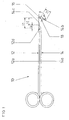
- FIG. 1 shows a first embodiment of a pair of scissors 10 according to the invention with a first hinge part 12 and a second hinge part 14, which are rotatably supported by a rotation axis 16 against each other.
- the two joint parts 12, 14 each have at a free axial end on one side of the axis of rotation 16 a scissor element 12b, 14b, which together form a working end 18.
- the working end 18 is angled by an angle ⁇ , which in the present case is about 125 °, in the plane of the scissors 10 from the axis of the hinge parts 12, 14.
- the free axial ends of the joint parts 12, 14 on the other side of the axis of rotation 16 pass over a mating surface 12c, 14c into a grip element 12a, 14a.
- the grip elements 12a, 14a are formed in the manner of the grip elements known scissors.
- the joint parts 12, 14 each have a closing bevel 12d, 14d which, starting from the counter surface 14c, 12c of the respective other joint part 14, 12, are offset in parallel by the amount b along the axis of the joint parts 12, 14 to the proximal end of the shear 10 ,
- a closing bevel 12d, 14d which, starting from the counter surface 14c, 12c of the respective other joint part 14, 12, are offset in parallel by the amount b along the axis of the joint parts 12, 14 to the proximal end of the shear 10 .
- the distance L1 from the rotation axis 16 to the end slopes 12d, 14d becomes greater than the distance L3 from the rotation axis 16 to the distal end of the scissor elements 12b, 14b.
- the distance L2 from the axis of rotation 16 to the mating surfaces 12c, 14c in this embodiment of the invention remains smaller than the distance L3 from the axis of rotation 16 to the distal ends of the scissor elements 12b, 14b (see FIG. FIG. 1a ).
- FIG. 1a The advantage of such an offset of the end bevels 12d, 14d is shown in FIG FIG. 1a in which the scissors 10 according to the invention with open joint parts 12, 14 is shown. Because the distance L1 from the end slope 14d to the rotation axis 16 is greater than the distance L3 from the rotation axis 16 to the distal end of the scissor element 12b, the joint part 12 can be opened wide with the scissor element 12b without the distal end of the scissor element 12b Scissors element 12b strikes the handle element 14a of the joint part 14 and the risk of breaking off of the distal end of the scissor element 12b could exist, since the distal end of the scissor element 12b can rotate past the grip element 14a of the joint part 14.
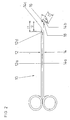
- FIG. 2 shows a further embodiment of the invention, wherein the same parts as in the first embodiment are designated by like reference numerals.
- the second embodiment differs from the embodiment in FIG. 1 only in that also the distance L2 from the counter surface 14c to the rotation axis 16 is greater than the distance L3 from the rotation axis 16 to the distal end of the scissor elements 12b, 14b.
- the distance L2 is approximately as large as the distance L1, so that the counter surface 14c on the end bevel 12d comes to rest only separated by a very small gap.
- Such scissors 10 can not be made from blanks in which the distances L1 and L2 are smaller than the distances L3, since in addition to the offset of the end bevels 12d, 14d, for which material must be removed, and the mating surfaces 12c, 14c to the proximal end be added, for which material would have to be added.
- FIG. 3 and 4 show two further embodiments of the invention, which differ from that in the FIG. 1 shown embodiment only by the configuration of the grip elements 12a, 14a differ.
- This in FIG. 3 embodiment shown has gripping elements 12a, 14a, which are slightly bent to enter the working end 18, depending on the operating room can be particularly easy.
- This in FIG. 4 shown working end has two handle elements 12a, 14a, which are held in the open state via two spring elements 12e, 14e, so that the shears of the working end 18 against the force of the spring elements 12e, 14e can be closed by squeezing the handle members 12a, 14a.
Landscapes
- Health & Medical Sciences (AREA)
- Life Sciences & Earth Sciences (AREA)
- Engineering & Computer Science (AREA)
- Surgery (AREA)
- Biomedical Technology (AREA)
- Molecular Biology (AREA)
- Nuclear Medicine, Radiotherapy & Molecular Imaging (AREA)
- Mechanical Engineering (AREA)
- Forests & Forestry (AREA)
- Heart & Thoracic Surgery (AREA)
- Medical Informatics (AREA)
- Pathology (AREA)
- Animal Behavior & Ethology (AREA)
- General Health & Medical Sciences (AREA)
- Public Health (AREA)
- Veterinary Medicine (AREA)
- Scissors And Nippers (AREA)
- Dry Shavers And Clippers (AREA)
- Glass Compositions (AREA)
Description
- Die Erfindung betrifft eine Schere gemäß dem Oberbegriff des Schutzanspruchs 1.
- Die
Figuren 5 und5a zeigen eine Schere 10 gemäß dem Stand der Technik mit einem ersten Gelenkteil 12 und einem zweiten Gelenkteil 14, welche um eine Drehachse 16 drehbar gegeneinander gelagert sind. Die Gelenkteile 12, 14 gehen an einem freien axialen Ende über eine Schlussschräge 12d, 14d und eine Gegenfläche 12c, 14c in ein Griffelement 12a, 14a über. An dem anderen freien axialen Ende der Gelenkteile 12, 14 ist ein mit Scherenelementen 12b, 14b ausgestattetes Arbeitsende 18 angeordnet. Werden die beiden Gelenkteile 12, 14 um die Drehachse 16 gedreht und vollständig geschlossen, kommt auf der Schlussschräge 12d des Gelenkteils 12 die Gegenfläche 14c des Gelenkteils 14 und auf der Schlussschräge 14d des Gelenkteils 14 die Gegenfläche 12c des Gelenkteils 13 jeweils nur durch einen sehr kleinen Spalt getrennt zu liegen. Sowohl die Schlussschrägen 12d, 14d als auch die Gegenflächen 12c, 14c verlaufen ausgehend von der Anlagefläche der beiden Gelenkteile 12, 14 schräg gegen die Achse der Schere 10 nach außen und bilden mit dem in Richtung des Arbeitsendes 18 weisenden Abschnitt der Achse der Schere 10 einen spitzen Winkel. - Im Folgenden wird der Abstand L1 zwischen der Drehachse 16 und der Schlussschräge 12d, 14d definiert als der Abstand L1 von der Drehachse 16 zum Schnittpunkt der Schlussschräge 12d, 14d mit der Außenseite des Gelenkteils 12, 14. Der Abstand L2 zwischen der Drehachse 16 und der Gegenfläche 12c, 14c ist definiert als der Abstand L2 von der Drehachse zum Schnittpunkt der Gegenfläche 12c, 14c mit der Außenseite des Gelenkteils 12, 14.
- Aus der Chirurgie sind derartige Scheren bekannt, bei welchen das Arbeitsende 18 um einen Winkel α, welcher insbesondere 20° bis 160° beträgt, in der Ebene der Schere 10 von der Achse der Gelenkteile 12, 14 abgewinkelt ist.
- Die Scherenelemente 12b, 14b des Arbeitsendes 18 laufen in einem spitzen distalen Ende aus und sind somit besonders empfindlich. Bei Belastung brechen diese distalen Enden der Scherenelemente 12b, 14b leicht ab. In
Figur 5a ist eine derartige Belastungssituation dargestellt, welche auftreten kann, wenn die beiden Gelenkteile 12, 14 besonders weit geöffnet werden, sodass das Scherenelement 12b des ersten Gelenkteils 12 auf das Griffelement 14a des zweiten Gelenkteils 14 aufschlägt. - Eine weitere derartige Schere ist auch aus
US 3,721,245 bekannt. - Die Aufgabe der Erfindung liegt darin, eine Schere bereit zu stellen, bei welcher die distalen Enden vor unnötiger Belastung, welche zu Zerstörung führen kann, geschützt werden.
- Die Aufgabe wird erfindungsgemäß gelöst durch eine Schere mit den Merkmalen des kennzeichnenden Teils des Schutzanspruchs 1.
- Vorteilhafte Weiterbildungen der Erfindung sind in den Unteransprüchen angegeben.
- Erfindungsgemäß ist der Abstand von der Drehachse zur Schlussschräge wenigstens eines der Gelenkteile größer als der Abstand von der Drehachse zum distalen Ende der Scherenelemente.
- Dies bedingt, dass auch bei großem Öffnungswinkel der beiden Gelenkteile gegeneinander das distale Ende des Scherenelements des ersten Gelenkteils nicht auf dem Griffelement des anderen Gelenkteils aufschlagen kann, sondern daran vorbei drehen kann. Die empfindlichen distalen Enden der Scherenelemente sind somit vor einem Abbrechen durch zu weites Öffnen der Schere und Aufschlagen auf dem Griffelement des anderen Gelenkteils geschützt.
- Vorzugsweise ist der Abstand der Drehachse zur Schlussschräge bei beiden Gelenkteilen größer als der Abstand von der Drehachse zum distalen Ende der Scherenelemente, um beide Scherenelemente entsprechend zu schützen.
- Bei einer vorteilhaften Weiterbildung der Erfindung ist der Abstand von der Drehachse zu einer Gegenfläche des Griffelements kleiner als der Abstand von der Drehachse zur Schlussschräge. Eine derartige Ausgestaltung kommt insbesondere dann zur Anwendung, wenn zur Herstellung der Gelenkteile normierte Rohlinge gemäß dem Stand der Technik verwendet werden, deren Abstand von der Drehachse zur Schlussschräge und somit ebenfalls zur Gegenfläche kleiner ist als der Abstand von der Drehachse zum distalen Ende der Scherenelemente. Um derartige Rohlinge zur Herstellung der erfindungsgemäßen Schere verwenden zu können, werden die Schlussschrägen parallel zum proximalen Ende der Gelenkteile hin versetzt, indem entsprechend Material von den Rohlingen entfernt wird. Die Schlussschrägen werden um einen bestimmten Betrag soweit parallel zum proximalen Ende der Gelenkteile versetzt, bis der Abstand der Drehachse zur Schlussschräge größer ist als der Abstand von der Drehachse zum distalen Ende des Scherenelements. In diesem Fall verbleibt jedoch der Abstand von der Drehachse zur Gegenfläche des Griffelements um den bestimmten Betrag kleiner als der Abstand von der Drehachse zur Schlussschräge. Auf diese Weise können besonders einfach bekannte Rohlinge zur Herstellung der erfindungsgemäßen Schere verwendet werden.
- In einer alternativen bevorzugten Ausführungsvariante der Erfindung entspricht der Abstand von der Drehachse zu der Gegenfläche in etwa dem Abstand von der Drehachse zur Schlussschräge der Gelenkteile. Somit sind beide Abstände größer als der Abstand von der Drehachse zum distalen Ende der Scherenelements. Zur Herstellung können keine Rohlinge gemäß dem Stand der Technik verwendet werden, dafür liegen jedoch im geschlossenen Zustand der Schere die Gegenflächen jeweils auf den Schlussschrägen auf.
- Bevorzugt beträgt der Winkel, um welchen das Arbeitsende abgewinkelt ist, 20° bis 160°. Besonders bevorzugt ist das Arbeitsende um 90° bis 135° in der Ebene der Schere von der Achse der Gelenkteile abgewinkelt. Bei kleineren Winkeln tritt das Problem einer Beschädigung der distalen Enden der Scherenelemente nur sehr selten auf, da dafür ein besonders großer Öffnungswinkel der beiden Gelenkteile von Nöten wäre, der jedoch sehr selten erreicht wird.
- Die Erfindung wird anhand der in den folgenden Figuren gezeigten Ausführungsbeispiele ausführlich erläutert. Es zeigt
- Fig. 1
- ein erstes Ausführungsbeispiel einer erfindungsgemäßen Schere,
- Fig. 1a
- die Schere aus
Fig. 1 in geöffnetem Zustand, - Fig. 2
- ein zweites Ausführungsbeispiel der Erfindung,
- Fig. 3
- ein drittes Ausführungsbeispiel der Erfindung,
- Fig. 4
- ein viertes Ausführungsbeispiel der Erfindung,
- Fig. 5
- ein Ausführungsbeispiel einer Schere gemäß dem Stand der Technik und
- Fig. 5a
- die Schere gemäß
Fig. 5 in geöffnetem Zustand. -
Figur 1 zeigt ein erstes Ausführungsbeispiel einer erfindungsgemäßen Schere 10 mit einem ersten Gelenkteil 12 und einem zweiten Gelenkteil 14, welche über eine Drehachse 16 drehbar gegeneinander gelagert sind. Die beiden Gelenkteile 12, 14 weisen an einem freien axialen Ende auf einer Seite der Drehachse 16 jeweils ein Scherenelement 12b, 14b auf, welche gemeinsam ein Arbeitsende 18 bilden. Das Arbeitsende 18 ist dabei um einen Winkel α, welcher vorliegend etwa 125° beträgt, in der Ebene der Schere 10 von der Achse der Gelenkteile 12, 14 abgewinkelt. Die freien axialen Enden der Gelenkteile 12, 14 auf der anderen Seite der Drehachse 16 gehen über eine Gegenfläche 12c, 14c in ein Griffelement 12a, 14a über. Die Griffelemente 12a, 14a sind dabei nach Art der Griffelemente bekannter Scheren ausgebildet. - Die Gelenkteile 12, 14 weisen jeweils eine Schlussschräge 12d, 14d auf, welche ausgehend von der Gegenfläche 14c, 12c des jeweils anderen Gelenkteils 14, 12 um den Betrag b entlang der Achse der Gelenkteile 12, 14 zum proximalen Ende der Schere 10 parallel versetzt sind. Dazu wurde ausgehend von einem Rohling, bei welchem die Schlussschrägen 12d, 14d direkt an den Gegenflächen 12c, 14c zu liegen kommen (vgl. bspw.
Figuren 5 und5a ), Material entfernt, um die Schlussschrägen 12d, 14d parallel zum proximalen Ende der Gelenkteile 12, 14 hin zu versetzen. Durch dieses Versetzen der Schlussschrägen 12d, 14d wird der Abstand L1 von der Drehachse 16 zu den Schlussschrägen 12d, 14d größer als der Abstand L3 von der Drehachse 16 zu dem distalen Ende der Scherenelemente 12b, 14b. Der Abstand L2 von der Drehachse 16 zu den Gegenflächen 12c, 14c verbleibt in diesem Ausführungsbeispiel der Erfindung kleiner als der Abstand L3 von der Drehachse 16 zu den distalen Enden der Scherenelemente 12b, 14b (vgl.Figur 1a ). - Der Vorteil eines derartigen Versatzes der Schlussschrägen 12d, 14d zeigt sich in
Figur 1a , in welcher die erfindungsgemäße Schere 10 mit geöffneten Gelenkteilen 12, 14 dargestellt ist. Dadurch, dass der Abstand L1 von der Schlussschräge 14d zu der Drehachse 16 größer ist als der Abstand L3 von der Drehachse 16 zu dem distalen Ende des Scherenelements 12b, lässt sich das Gelenkteil 12 mit dem Scherenelement 12b weit öffnen, ohne dass das distale Ende des Scherenelements 12b auf dem Griffelement 14a des Gelenkteils 14 aufschlägt und die Gefahr des Abbrechens des distalen Endes des Scherenelements 12b bestehen könnte, da das distale Ende des Scherenelements 12b an dem Griffelement 14a des Gelenkteils 14 vorbeidrehen kann. -
Figur 2 zeigt ein weiteres Ausführungsbeispiel der Erfindung, bei welchem gleiche Teile wie im ersten Ausführungsbeispiel mit gleichen Bezugsziffern bezeichnet sind. Das zweite Ausführungsbeispiel unterscheidet sich von dem Ausführungsbeispiel inFigur 1 nur-dadurch, dass auch der Abstand L2 von der Gegenfläche 14c zur Drehachse 16 größer ist als der Abstand L3 von der Drehachse 16 zum distalen Ende der Scherenelemente 12b, 14b. Der Abstand L2 ist in etwa so groß wie der Abstand L1, sodass die Gegenfläche 14c auf der Schlussschräge 12d nur durch einen sehr kleinen Spalt getrennt zu liegen kommt. Eine derartige Schere 10 kann nicht aus Rohlingen hergestellt werden, bei welchen die Abstände L1 und L2 kleiner sind als die Abstände L3, da zusätzlich zum Versatz der Schlussschrägen 12d, 14d, für welche Material entfernt werden muss, auch die Gegenflächen 12c, 14c zum proximalen Ende versetzt werden, wofür Material hinzugefügt werden müsste. - Die
Figuren 3 und4 zeigen zwei weitere Ausführungsbeispiele der Erfindung, welche sich von dem in derFigur 1 gezeigten Ausführungsbeispiel nur durch die Ausgestaltung der Griffelemente 12a, 14a unterscheiden. Das inFigur 3 gezeigte Ausführungsbeispiel weist Griffelemente 12a, 14a auf, welche leicht gebogen sind, um je nach Operationsraum das Arbeitsende 18 besonders leicht einführen zu können. Das inFigur 4 gezeigte Arbeitsende weist zwei Griffelemente 12a, 14a auf, welche über zwei Federelemente 12e, 14e in geöffnetem Zustand gehalten werden, sodass die Schere des Arbeitsendes 18 gegen die Kraft der Federelemente 12e, 14e durch Zusammendrücken der Griffelemente 12a, 14a geschlossen werden kann. -
- 10
- Schere
- 12
- erstes Gelenkteil
- 12a
- Griffelement
- 12b
- Scherenelement
- 12c
- Gegenfläche
- 12d
- Schlussschräge
- 12e
- Federelement
- 14
- zweites Gelenkteil
- 14a
- Griffelement
- 14b
- Scherenelement
- 14c
- Gegenfläche
- 14d
- Schlussschräge
- 14e
- Federelement
- 16
- Drehachse
- 18
- Arbeitsende
- L1
- Abstand
- L2
- Abstand
- L3
- Abstand
- α
- Winkel
- b
- Betrag
Claims (6)
- Schere mit zwei Gelenkteilen (12, 14), welche um eine Drehachse (16) drehbar gegeneinander gelagert sind, welche an einem freien axialen Ende über eine Schlussschräge (12d, 14d) und eine Gegenfläche (12c, 14c) in ein Griffelement (12a, 14a) übergehen und welche an dem anderen freien axialen Ende ein mit Scherenelementen (12b, 14b) ausgestattetes Arbeitsende (18) aufweisen, wobei das Arbeitsende (18) um einen Winkel (α) in der Ebene der Schere (10) von der Achse der Gelenkteile (12, 14) abgewinkelt ist,
dadurch gekennzeichnet, dass
der Abstand (L1) von der Drehachse (16) zur Schlussschräge (12d, 14d) wenigstens eines der Gelenkteile (12, 14) größer ist als der Abstand (13) von der Drehachse (16) zum distalen Ende der Scherenelemente (12b, 14b). - Schere nach Anspruch 1,
dadurch gekennzeichnet, dass
der Abstand (L1) der Drehachse (16) zur Schlussschräge (12d, 14d) bei beiden Gelenkteilen (12, 14) größer ist als der Abstand (13) von der Drehachse (16) zum distalen Ende der Scherenelemente (12b, 14b). - Schere nach Anspruch 1 oder 2,
dadurch gekennzeichnet, dass
der Abstand (L2) von der Drehachse (16) zu der Gegenfläche (12c, 14c) um einen Betrag (b) kleiner ist als der Abstand (11) von der Drehachse (16) zur Schlussschräge (12d, 14d). - Schere nach Anspruch 1 oder 2,
dadurch gekennzeichnet, dass
der Abstand (L2) von der Drehachse (16) zu der Gegenfläche (12c, 14c) in etwa dem Abstand (L1) von der Drehachse (16) zur Schlussschräge (12d, 14d) entspricht. - Schere nach einem der vorhergehenden Ansprüche,
dadurch gekennzeichnet, dass
der Winkel (α) etwa 20° bis 160° beträgt. - Schere nach einem der vorhergehenden Ansprüche,
dadurchgekennzeichnet, dass
der Winkel (α) etwa 90° bis 135° beträgt.
Applications Claiming Priority (2)
| Application Number | Priority Date | Filing Date | Title |
|---|---|---|---|
| DE202004014750U DE202004014750U1 (de) | 2004-09-20 | 2004-09-20 | Schere |
| PCT/EP2005/009874 WO2006032395A1 (de) | 2004-09-20 | 2005-09-14 | Schere |
Publications (2)
| Publication Number | Publication Date |
|---|---|
| EP1796882A1 EP1796882A1 (de) | 2007-06-20 |
| EP1796882B1 true EP1796882B1 (de) | 2008-08-20 |
Family
ID=35432612
Family Applications (1)
| Application Number | Title | Priority Date | Filing Date |
|---|---|---|---|
| EP05787094A Expired - Lifetime EP1796882B1 (de) | 2004-09-20 | 2005-09-14 | Schere |
Country Status (5)
| Country | Link |
|---|---|
| US (1) | US20070283571A1 (de) |
| EP (1) | EP1796882B1 (de) |
| AT (1) | ATE405389T1 (de) |
| DE (2) | DE202004014750U1 (de) |
| WO (1) | WO2006032395A1 (de) |
Family Cites Families (14)
| Publication number | Priority date | Publication date | Assignee | Title |
|---|---|---|---|---|
| US359684A (en) * | 1887-03-22 | Wire-cutter | ||
| US123234A (en) * | 1872-01-30 | Improvement in pruning-shears | ||
| US2568234A (en) * | 1949-03-09 | 1951-09-18 | Roy Tashnek | Episiotomy scissors |
| US2760264A (en) * | 1952-07-18 | 1956-08-28 | Benjamin A Javits | Device to aid in attaching false eyelashes to real eyelashes and for trimming the same |
| DE1804028U (de) * | 1959-08-11 | 1960-01-14 | Siegfried Martin | Schere fuer hirnoperationen. |
| US3583264A (en) * | 1968-02-23 | 1971-06-08 | Bahco Ab | Arrangement in handtools, such as pliers, pincers and the like |
| US3721245A (en) * | 1971-05-04 | 1973-03-20 | A Campbell | Pair of surgical scissors |
| US6079107A (en) * | 1998-05-11 | 2000-06-27 | Horvath; Joseph Paul | Trimming device for beards |
| US6395010B1 (en) * | 1999-12-21 | 2002-05-28 | Securos, Inc. | Crimping device for cranial cruciate ligament stabilization |
| DE10028896B4 (de) * | 2000-06-10 | 2007-11-22 | Karl Storz Gmbh & Co. Kg | Medizinisches Instrument |
| US20020023354A1 (en) * | 2000-08-22 | 2002-02-28 | Lowe Joseph T. | Combined shears and loppers |
| FR2835694B1 (fr) * | 2002-02-08 | 2004-04-02 | Deville Sa | Secateur |
| US6976992B2 (en) * | 2002-07-16 | 2005-12-20 | Suturecut, Llc | Dual-function medical instrument |
| US7497867B2 (en) * | 2004-07-12 | 2009-03-03 | Jeffrey Lasner | Handles and shafts for manually adjustable scissors and forceps |
-
2004
- 2004-09-20 DE DE202004014750U patent/DE202004014750U1/de not_active Expired - Lifetime
-
2005
- 2005-09-14 WO PCT/EP2005/009874 patent/WO2006032395A1/de not_active Ceased
- 2005-09-14 US US11/575,561 patent/US20070283571A1/en not_active Abandoned
- 2005-09-14 DE DE502005005143T patent/DE502005005143D1/de not_active Expired - Lifetime
- 2005-09-14 EP EP05787094A patent/EP1796882B1/de not_active Expired - Lifetime
- 2005-09-14 AT AT05787094T patent/ATE405389T1/de not_active IP Right Cessation
Also Published As
| Publication number | Publication date |
|---|---|
| DE202004014750U1 (de) | 2006-02-09 |
| WO2006032395A1 (de) | 2006-03-30 |
| US20070283571A1 (en) | 2007-12-13 |
| ATE405389T1 (de) | 2008-09-15 |
| EP1796882A1 (de) | 2007-06-20 |
| DE502005005143D1 (de) | 2008-10-02 |
Similar Documents
| Publication | Publication Date | Title |
|---|---|---|
| DE69700430T2 (de) | Flüssigkeitsausgabevorrichtung mit doppelter sichercheit | |
| DE69912265T2 (de) | Vorrichtung zum gegenseitigen verriegeln zweier teile | |
| DE202013001957U1 (de) | Betätigungshandhabe | |
| DE102007037382B4 (de) | Zange | |
| DE29612857U1 (de) | Endoprothese | |
| DE102009059198A1 (de) | Zange | |
| WO2011069179A1 (de) | Möbelscharnier | |
| EP3580024B1 (de) | Schere | |
| EP1253676A2 (de) | Elektrischer Steckverbinder | |
| DE202010005089U1 (de) | Sterilcontainer für medizinische Zwecke | |
| EP2774869A1 (de) | Behälterverschluss | |
| DE102016222831A1 (de) | Scharnier mit einer in einer vorbestimmten Winkelstellung lösbaren Scharnierkomponente | |
| DE202004014750U1 (de) | Schere | |
| DE202006002436U1 (de) | Clip-Anlegezange | |
| EP3784440B1 (de) | Zange | |
| DE102017131355B4 (de) | Gelenkschere mit magnetischem Scherenschloss | |
| CH714248B1 (de) | Mehrteiliges Gehäuse für Verbrauchszähler sowie Sicherungseinrichtung für mehrteilige Gehäuse. | |
| EP3684992B1 (de) | Schaltschrank mit verbesserter schliessmechanik | |
| DE19618762C2 (de) | Verfahren zur Herstellung eines Türstoppers oder dergleichen, insbesondere für Automobile | |
| EP3736243B1 (de) | Sicherheitslasthaken | |
| EP1658413B1 (de) | Bodentürschliesser | |
| DE102022111004A1 (de) | Vorrichtung zum Öffnen und Schließen von Probenbehältern mit einem Greiffinger mit konvex gekrümmter Oberfläche und entsprechender Greiffinger | |
| DE102020125517A1 (de) | Fahrzeugtürgriffmechanismus | |
| EP3354617A1 (de) | Drehverschlussöffner und verfahren zum öffnen eines drehverschlusses | |
| DE1935217A1 (de) | Selbstrueckstellender Sicherheitslenker fuer verstellbare Schaufeln von Stroemungsmaschinen |
Legal Events
| Date | Code | Title | Description |
|---|---|---|---|
| PUAI | Public reference made under article 153(3) epc to a published international application that has entered the european phase |
Free format text: ORIGINAL CODE: 0009012 |
|
| AK | Designated contracting states |
Kind code of ref document: A1 Designated state(s): AT BE BG CH CY CZ DE DK EE ES FI FR GB GR HU IE IS IT LI LT LU LV MC NL PL PT RO SE SI SK TR |
|
| 17P | Request for examination filed |
Effective date: 20070314 |
|
| RIN1 | Information on inventor provided before grant (corrected) |
Inventor name: MOSER, KLAUS |
|
| DAX | Request for extension of the european patent (deleted) | ||
| GRAP | Despatch of communication of intention to grant a patent |
Free format text: ORIGINAL CODE: EPIDOSNIGR1 |
|
| GRAS | Grant fee paid |
Free format text: ORIGINAL CODE: EPIDOSNIGR3 |
|
| GRAA | (expected) grant |
Free format text: ORIGINAL CODE: 0009210 |
|
| AK | Designated contracting states |
Kind code of ref document: B1 Designated state(s): AT BE BG CH CY CZ DE DK EE ES FI FR GB GR HU IE IS IT LI LT LU LV MC NL PL PT RO SE SI SK TR |
|
| REG | Reference to a national code |
Ref country code: GB Ref legal event code: FG4D Free format text: NOT ENGLISH |
|
| REG | Reference to a national code |
Ref country code: CH Ref legal event code: EP |
|
| REG | Reference to a national code |
Ref country code: IE Ref legal event code: FG4D Free format text: LANGUAGE OF EP DOCUMENT: GERMAN |
|
| REF | Corresponds to: |
Ref document number: 502005005143 Country of ref document: DE Date of ref document: 20081002 Kind code of ref document: P |
|
| PG25 | Lapsed in a contracting state [announced via postgrant information from national office to epo] |
Ref country code: NL Free format text: LAPSE BECAUSE OF FAILURE TO SUBMIT A TRANSLATION OF THE DESCRIPTION OR TO PAY THE FEE WITHIN THE PRESCRIBED TIME-LIMIT Effective date: 20080820 Ref country code: IS Free format text: LAPSE BECAUSE OF FAILURE TO SUBMIT A TRANSLATION OF THE DESCRIPTION OR TO PAY THE FEE WITHIN THE PRESCRIBED TIME-LIMIT Effective date: 20081220 Ref country code: LT Free format text: LAPSE BECAUSE OF FAILURE TO SUBMIT A TRANSLATION OF THE DESCRIPTION OR TO PAY THE FEE WITHIN THE PRESCRIBED TIME-LIMIT Effective date: 20080820 |
|
| PG25 | Lapsed in a contracting state [announced via postgrant information from national office to epo] |
Ref country code: LV Free format text: LAPSE BECAUSE OF FAILURE TO SUBMIT A TRANSLATION OF THE DESCRIPTION OR TO PAY THE FEE WITHIN THE PRESCRIBED TIME-LIMIT Effective date: 20080820 Ref country code: ES Free format text: LAPSE BECAUSE OF FAILURE TO SUBMIT A TRANSLATION OF THE DESCRIPTION OR TO PAY THE FEE WITHIN THE PRESCRIBED TIME-LIMIT Effective date: 20081201 Ref country code: FI Free format text: LAPSE BECAUSE OF FAILURE TO SUBMIT A TRANSLATION OF THE DESCRIPTION OR TO PAY THE FEE WITHIN THE PRESCRIBED TIME-LIMIT Effective date: 20080820 Ref country code: SI Free format text: LAPSE BECAUSE OF FAILURE TO SUBMIT A TRANSLATION OF THE DESCRIPTION OR TO PAY THE FEE WITHIN THE PRESCRIBED TIME-LIMIT Effective date: 20080820 |
|
| BERE | Be: lapsed |
Owner name: GIMMI G.M.B.H. Effective date: 20080930 |
|
| REG | Reference to a national code |
Ref country code: IE Ref legal event code: FD4D |
|
| PG25 | Lapsed in a contracting state [announced via postgrant information from national office to epo] |
Ref country code: BG Free format text: LAPSE BECAUSE OF FAILURE TO SUBMIT A TRANSLATION OF THE DESCRIPTION OR TO PAY THE FEE WITHIN THE PRESCRIBED TIME-LIMIT Effective date: 20081120 Ref country code: DK Free format text: LAPSE BECAUSE OF FAILURE TO SUBMIT A TRANSLATION OF THE DESCRIPTION OR TO PAY THE FEE WITHIN THE PRESCRIBED TIME-LIMIT Effective date: 20080820 Ref country code: IE Free format text: LAPSE BECAUSE OF FAILURE TO SUBMIT A TRANSLATION OF THE DESCRIPTION OR TO PAY THE FEE WITHIN THE PRESCRIBED TIME-LIMIT Effective date: 20080820 Ref country code: MC Free format text: LAPSE BECAUSE OF NON-PAYMENT OF DUE FEES Effective date: 20080930 |
|
| PG25 | Lapsed in a contracting state [announced via postgrant information from national office to epo] |
Ref country code: RO Free format text: LAPSE BECAUSE OF FAILURE TO SUBMIT A TRANSLATION OF THE DESCRIPTION OR TO PAY THE FEE WITHIN THE PRESCRIBED TIME-LIMIT Effective date: 20080820 Ref country code: CZ Free format text: LAPSE BECAUSE OF FAILURE TO SUBMIT A TRANSLATION OF THE DESCRIPTION OR TO PAY THE FEE WITHIN THE PRESCRIBED TIME-LIMIT Effective date: 20080820 Ref country code: PT Free format text: LAPSE BECAUSE OF FAILURE TO SUBMIT A TRANSLATION OF THE DESCRIPTION OR TO PAY THE FEE WITHIN THE PRESCRIBED TIME-LIMIT Effective date: 20090120 Ref country code: SK Free format text: LAPSE BECAUSE OF FAILURE TO SUBMIT A TRANSLATION OF THE DESCRIPTION OR TO PAY THE FEE WITHIN THE PRESCRIBED TIME-LIMIT Effective date: 20080820 |
|
| PLBE | No opposition filed within time limit |
Free format text: ORIGINAL CODE: 0009261 |
|
| STAA | Information on the status of an ep patent application or granted ep patent |
Free format text: STATUS: NO OPPOSITION FILED WITHIN TIME LIMIT |
|
| 26N | No opposition filed |
Effective date: 20090525 |
|
| PG25 | Lapsed in a contracting state [announced via postgrant information from national office to epo] |
Ref country code: BE Free format text: LAPSE BECAUSE OF NON-PAYMENT OF DUE FEES Effective date: 20080930 Ref country code: EE Free format text: LAPSE BECAUSE OF FAILURE TO SUBMIT A TRANSLATION OF THE DESCRIPTION OR TO PAY THE FEE WITHIN THE PRESCRIBED TIME-LIMIT Effective date: 20080820 |
|
| PG25 | Lapsed in a contracting state [announced via postgrant information from national office to epo] |
Ref country code: IT Free format text: LAPSE BECAUSE OF FAILURE TO SUBMIT A TRANSLATION OF THE DESCRIPTION OR TO PAY THE FEE WITHIN THE PRESCRIBED TIME-LIMIT Effective date: 20080820 |
|
| REG | Reference to a national code |
Ref country code: FR Ref legal event code: ST Effective date: 20090731 |
|
| PG25 | Lapsed in a contracting state [announced via postgrant information from national office to epo] |
Ref country code: AT Free format text: LAPSE BECAUSE OF NON-PAYMENT OF DUE FEES Effective date: 20080914 |
|
| PG25 | Lapsed in a contracting state [announced via postgrant information from national office to epo] |
Ref country code: SE Free format text: LAPSE BECAUSE OF FAILURE TO SUBMIT A TRANSLATION OF THE DESCRIPTION OR TO PAY THE FEE WITHIN THE PRESCRIBED TIME-LIMIT Effective date: 20081120 |
|
| PGFP | Annual fee paid to national office [announced via postgrant information from national office to epo] |
Ref country code: DE Payment date: 20091026 Year of fee payment: 5 |
|
| REG | Reference to a national code |
Ref country code: CH Ref legal event code: PL |
|
| GBPC | Gb: european patent ceased through non-payment of renewal fee |
Effective date: 20090914 |
|
| PG25 | Lapsed in a contracting state [announced via postgrant information from national office to epo] |
Ref country code: PL Free format text: LAPSE BECAUSE OF FAILURE TO SUBMIT A TRANSLATION OF THE DESCRIPTION OR TO PAY THE FEE WITHIN THE PRESCRIBED TIME-LIMIT Effective date: 20080820 |
|
| PG25 | Lapsed in a contracting state [announced via postgrant information from national office to epo] |
Ref country code: HU Free format text: LAPSE BECAUSE OF FAILURE TO SUBMIT A TRANSLATION OF THE DESCRIPTION OR TO PAY THE FEE WITHIN THE PRESCRIBED TIME-LIMIT Effective date: 20090221 Ref country code: CY Free format text: LAPSE BECAUSE OF FAILURE TO SUBMIT A TRANSLATION OF THE DESCRIPTION OR TO PAY THE FEE WITHIN THE PRESCRIBED TIME-LIMIT Effective date: 20080820 Ref country code: LU Free format text: LAPSE BECAUSE OF NON-PAYMENT OF DUE FEES Effective date: 20080914 |
|
| PG25 | Lapsed in a contracting state [announced via postgrant information from national office to epo] |
Ref country code: TR Free format text: LAPSE BECAUSE OF FAILURE TO SUBMIT A TRANSLATION OF THE DESCRIPTION OR TO PAY THE FEE WITHIN THE PRESCRIBED TIME-LIMIT Effective date: 20080820 |
|
| PG25 | Lapsed in a contracting state [announced via postgrant information from national office to epo] |
Ref country code: CH Free format text: LAPSE BECAUSE OF NON-PAYMENT OF DUE FEES Effective date: 20090930 Ref country code: LI Free format text: LAPSE BECAUSE OF NON-PAYMENT OF DUE FEES Effective date: 20090930 Ref country code: GR Free format text: LAPSE BECAUSE OF FAILURE TO SUBMIT A TRANSLATION OF THE DESCRIPTION OR TO PAY THE FEE WITHIN THE PRESCRIBED TIME-LIMIT Effective date: 20081121 |
|
| PG25 | Lapsed in a contracting state [announced via postgrant information from national office to epo] |
Ref country code: GB Free format text: LAPSE BECAUSE OF NON-PAYMENT OF DUE FEES Effective date: 20090914 |
|
| REG | Reference to a national code |
Ref country code: DE Ref legal event code: R119 Ref document number: 502005005143 Country of ref document: DE Effective date: 20110401 |
|
| PG25 | Lapsed in a contracting state [announced via postgrant information from national office to epo] |
Ref country code: DE Free format text: LAPSE BECAUSE OF NON-PAYMENT OF DUE FEES Effective date: 20110401 |
|
| PG25 | Lapsed in a contracting state [announced via postgrant information from national office to epo] |
Ref country code: FR Free format text: LAPSE BECAUSE OF NON-PAYMENT OF DUE FEES Effective date: 20081020 |