EP1796561B1 - Knochenschraube - Google Patents
Knochenschraube Download PDFInfo
- Publication number
- EP1796561B1 EP1796561B1 EP05796158.3A EP05796158A EP1796561B1 EP 1796561 B1 EP1796561 B1 EP 1796561B1 EP 05796158 A EP05796158 A EP 05796158A EP 1796561 B1 EP1796561 B1 EP 1796561B1
- Authority
- EP
- European Patent Office
- Prior art keywords
- bone screw
- securing
- securing element
- bone
- snap
- Prior art date
- Legal status (The legal status is an assumption and is not a legal conclusion. Google has not performed a legal analysis and makes no representation as to the accuracy of the status listed.)
- Expired - Lifetime
Links
Images



Classifications
-
- A—HUMAN NECESSITIES
- A61—MEDICAL OR VETERINARY SCIENCE; HYGIENE
- A61B—DIAGNOSIS; SURGERY; IDENTIFICATION
- A61B17/00—Surgical instruments, devices or methods
- A61B17/56—Surgical instruments or methods for treatment of bones or joints; Devices specially adapted therefor
- A61B17/58—Surgical instruments or methods for treatment of bones or joints; Devices specially adapted therefor for osteosynthesis, e.g. bone plates, screws or setting implements
- A61B17/68—Internal fixation devices, including fasteners and spinal fixators, even if a part thereof projects from the skin
- A61B17/80—Cortical plates, i.e. bone plates; Instruments for holding or positioning cortical plates, or for compressing bones attached to cortical plates
- A61B17/8033—Cortical plates, i.e. bone plates; Instruments for holding or positioning cortical plates, or for compressing bones attached to cortical plates having indirect contact with screw heads, or having contact with screw heads maintained with the aid of additional components, e.g. nuts, wedges or head covers
- A61B17/8038—Cortical plates, i.e. bone plates; Instruments for holding or positioning cortical plates, or for compressing bones attached to cortical plates having indirect contact with screw heads, or having contact with screw heads maintained with the aid of additional components, e.g. nuts, wedges or head covers the additional component being inserted in the screw head
-
- A—HUMAN NECESSITIES
- A61—MEDICAL OR VETERINARY SCIENCE; HYGIENE
- A61B—DIAGNOSIS; SURGERY; IDENTIFICATION
- A61B17/00—Surgical instruments, devices or methods
- A61B17/56—Surgical instruments or methods for treatment of bones or joints; Devices specially adapted therefor
- A61B17/58—Surgical instruments or methods for treatment of bones or joints; Devices specially adapted therefor for osteosynthesis, e.g. bone plates, screws or setting implements
- A61B17/68—Internal fixation devices, including fasteners and spinal fixators, even if a part thereof projects from the skin
- A61B17/84—Fasteners therefor or fasteners being internal fixation devices
- A61B17/86—Pins or screws or threaded wires; nuts therefor
- A61B17/8685—Pins or screws or threaded wires; nuts therefor comprising multiple separate parts
-
- A—HUMAN NECESSITIES
- A61—MEDICAL OR VETERINARY SCIENCE; HYGIENE
- A61B—DIAGNOSIS; SURGERY; IDENTIFICATION
- A61B17/00—Surgical instruments, devices or methods
- A61B17/56—Surgical instruments or methods for treatment of bones or joints; Devices specially adapted therefor
- A61B17/58—Surgical instruments or methods for treatment of bones or joints; Devices specially adapted therefor for osteosynthesis, e.g. bone plates, screws or setting implements
- A61B17/68—Internal fixation devices, including fasteners and spinal fixators, even if a part thereof projects from the skin
- A61B17/84—Fasteners therefor or fasteners being internal fixation devices
- A61B17/86—Pins or screws or threaded wires; nuts therefor
- A61B17/864—Pins or screws or threaded wires; nuts therefor hollow, e.g. with socket or cannulated
-
- A—HUMAN NECESSITIES
- A61—MEDICAL OR VETERINARY SCIENCE; HYGIENE
- A61B—DIAGNOSIS; SURGERY; IDENTIFICATION
- A61B17/00—Surgical instruments, devices or methods
- A61B2017/00535—Surgical instruments, devices or methods pneumatically or hydraulically operated
- A61B2017/00539—Surgical instruments, devices or methods pneumatically or hydraulically operated hydraulically
-
- A—HUMAN NECESSITIES
- A61—MEDICAL OR VETERINARY SCIENCE; HYGIENE
- A61B—DIAGNOSIS; SURGERY; IDENTIFICATION
- A61B17/00—Surgical instruments, devices or methods
- A61B2017/00535—Surgical instruments, devices or methods pneumatically or hydraulically operated
- A61B2017/00557—Surgical instruments, devices or methods pneumatically or hydraulically operated inflatable
-
- A—HUMAN NECESSITIES
- A61—MEDICAL OR VETERINARY SCIENCE; HYGIENE
- A61B—DIAGNOSIS; SURGERY; IDENTIFICATION
- A61B17/00—Surgical instruments, devices or methods
- A61B2017/00831—Material properties
- A61B2017/00867—Material properties shape memory effect
Definitions
- the present invention relates to a bone screw having a shaft defining a longitudinal axis and having a head engageable with a bone screw receptacle of a bone plate for releasably connecting the bone screw to the bone plate, wherein a securing element for securing a connection of the bone screw and the bone plate is provided wherein the bone screw from an engagement position, in which the bone screw is held on the bone plate, can be brought into a release position in which the bone screw is detachable from the bone plate, wherein the securing element of a Entommeswolf in which the bone screw can be brought into the release position , in a securing position for securing the connection between the bone screw and the bone plate can be brought, in which the bone screw occupies the engagement position, wherein the bone screw in a normal position in which no outer Acting forces acting on them, the engagement position assumes, wherein the shaft has a securing element receiving and the securing element is mounted in the securing element receiving, wherein after insertion
- Bone screws of the type described above are for example from the EP 1 306 058 A2 , of the US 5,902,303 , of the US 6,117,173 , of the EP 0 809 974 A2 as well as the US 6,039,740 and are used in surgery to fix bone plates to bone parts of a human or animal body.
- Advantage of these screws is that the engagement position can be locked, so that the bone plate under load not from the or Can loosen bone screws.
- are known locking elements which are arranged on the bone plate and are pushed over the head of the screwed bone screw. This has the disadvantage that at each opening of the bone plate, a securing element must be provided.
- the securing elements arranged on the unused bone screw receptacles are basically superfluous. Furthermore, it must be ensured before inserting the bone plate that all fuse elements occupy the armed position. If this is not the case, then all the fuse elements must be transferred during the procedure from the securing position to the armed position, which unnecessarily prolongs an operating time.
- each bone screw includes its own security element.
- the securing element is mounted captively movable on the bone screw. This can be achieved, in particular with very small bone screws, as they For example, be used in the cervical region of the spine, the fuse element is easy and easy from the securing position in the armed position and vice versa can be transferred. Also, it can not get lost in an operating area. So that in the engaged position no stresses on the bone screw, which can lead to damage of the same under continuous load, it is advantageous that the bone screw assumes the engaged position without the action of external forces.
- the shaft has a securing element receiving and that the securing element is mounted in the securing element receiving. So that the securing element can be held captive on the bone screw, it is advantageous that after insertion of the securing element into the securing element receiving the securing element in the axial direction between a distal and a proximal acting stop can be moved.
- the securing element can therefore be moved in the axial direction against the stop acting in the proximal direction, against which it rests, for example, in the unlocking position. Furthermore, the securing element can be moved against the stop acting in the distal direction and abut against it when, for example, it assumes the securing position.
- the securing element is held in the basic position of the bone screw, in which no external forces acting on the bone screw, in the securing position. This has the advantage that a doctor does not have to remember to lock the bone screw, since they are in a basic position the securing position occupies. This shortens the operation time and avoids errors. It also reduces the number of instruments required because no special instrument is needed for the fuse element.
- the bone screw can also be designed so that no forces acting on the securing element in the securing position, the securing element is thus held free of forces. It is advantageous that the securing element is held in the securing position under bias. For transferring the securing element from the securing position in the armed position against the bias, therefore, a certain release force is applied. Since the fuse element is held under pretension, it is automatically returned again from the armed position to the secured position. Therefore, a doctor need not lock each bone screw individually, the bone screw locked by the particular design itself.
- a particularly simple design of the bone screw results when it is rotationally symmetrical or substantially rotationally symmetrical to the longitudinal axis.
- the head In the engaged position, the head preferably has a maximum outer dimension transversely to the longitudinal axis and in the release position a reduced outer dimension compared to the maximum outer dimension. This allows the head to be disengaged from a portion of the bone plate, such as the bone screw receptacle, in the engaged position and disengaged in the disengaged position.
- the head can have any shape, for example, with an angular or round cross-section transverse to the longitudinal axis.
- the head in the engagement position, has a maximum outside diameter transverse to the longitudinal axis and in the release position an outside diameter reduced in relation to the maximum outside diameter.
- the head can be compressed starting from the engagement position for transferring the bone screw in the release position or be spread apart from the release position for transferring the bone screw in the engaged position. Therefore, it would be conceivable to design the bone screw so that it occupies either the engagement position or the release position without the action of external forces.
- a connection between the bone screw and the bone plate can be produced in a particularly simple manner, when the head carries a first locking element, which is latched in the engaged position with a arranged on the bone plate second locking element.
- the two locking elements can thus be in the engaged position in engagement, in particular intermesh positively.
- the construction of the bone screw can be made particularly simple if the first locking element is a circumferentially extending, radially open annular groove or extending in the circumferential direction, radially outwardly projecting annular projection.
- the annular groove can record, for example, a corresponding projection or corresponding projections on the bone plate.
- the protruding annular projection may be engaged with a corresponding groove on the bone plate for establishing a connection between the bone screw and the bone plate.
- the securing element can be arranged in a cavity or a recess of the shaft, in which it is also protected.
- Defined holding forces in different positions of the securing element can be generated when the holding element is an elastic element.
- the structure of the bone screw when the holding element is a coil spring or a plate spring or package of disc springs.
- a desired holding force, with which the securing element is held in the securing position or held in this under bias, can be adjusted in a simple manner.
- the holding element is designed such that an outer dimension and / or a volume of the holding element by changing at least one state variable in an environment of the bone screw is changeable. For example, in the vicinity of the bone screw, a pressure can be increased, with the result that the volume of the holding element is increased or decreased.
- the securing element can be transferred from the armed position to the securing position and / or vice versa.
- the at least one state variable is an ambient temperature, an ambient pressure, an osmotic pressure or a humidity the environment is. This makes it possible to change the state of the holding element, in particular an outer dimension and / or a volume of the same by changing the said or other physical quantities in the vicinity of the bone screw.
- the retaining element is made of a memory metal.
- the securing element can be moved in a simple manner if the holding element is inflatable by a fluid.
- the fluid may be air, compressed air or a biocompatible fluid.
- the holding element has an interior, which is in fluid communication via a semipermeable membrane with an environment of the bone screw. This allows, for example, to let water einifundieren in the interior of the holding element as a function of a solvent concentration in the vicinity of the bone screw.
- a backup of the bone screw in the engaged position can be achieved particularly easily if the securing element is mounted parallel to the longitudinal axis displaceable on the shaft.
- the bone screw is particularly easy to produce when the fuse element receptacle is a blind hole.
- the fuse element can then first be inserted into the securing element receiving through an opening of the blind hole, but not on the other side of the recess again emerge from the bone screw.
- the blind hole is arranged so that an opening thereof is arranged in the region of the head of the bone screw.
- the securing element is rotationally positively held in the securing element receiving.
- This allows a force to be introduced to the bone screw for screwing the same into a bone part via the securing element and can be transmitted to the shaft of the bone screw by the rotationally positive-locking design of the securing element receptacle. So it is particularly possible to provide a tool adapter for a screwing the bone screw on the fuse element itself.
- the stability of the bone screw is increased overall if the securing element has a securing element section, which is designed in the form of an outer polyhedron, and if the securing element receiving has a securing element receiving section, which is designed in the form of an external polygon corresponding to the inner polygon.
- the outer polyhedron can be formed as a square, hexagon or octagon.
- the first locking element is mounted movably on the bone screw in the radial direction. It can therefore from the longitudinal axis in radial Direction away or to be moved to this.
- the locking elements may in particular be mounted displaceably or pivotably on the bone screw.
- a connection between the bone screw and the bone plate can be produced in a simple manner if the head comprises a plurality of transversely movable to the longitudinal axis locking elements, which are in the engaged position with the bone plate engaged.
- the bone screw has a securing element receptacle
- at least part of the bone screw is sleeve-shaped.
- the head has flap-like wall sections extending parallel to the longitudinal axis and if the wall sections form the locking elements.
- the wall sections form the locking elements.
- only the head of the bone screw has to be slotted in order to produce the locking elements.
- four, five or six locking elements are provided which can be formed by four, five or six slots distributed symmetrically over a circumference of the bone screw.
- the locking elements occupy the engagement position in a basic position in which no external forces act on the bone screw.
- the locking elements must therefore be moved only to transfer the bone screw from the engaged position to the release position and are only for a short time under tension. In the engaged position, however, they are essentially stress-free, so that there is no danger that the locking elements can break under continuous load.
- the locking elements are moved radially in the direction of the longitudinal axis. Therefore, the locking elements are favorably movable radially outward from the engagement position for insertion of the securing element in the securing element receiving. In other words, this means that the securing element spreads the locking elements and thus, for example, a head of the bone screw when inserted into the securing element receptacle.
- the locking elements After insertion of the securing element in the securing element receiving the locking elements then return to their original shape, in which they take the engaged position.
- the fuse element is then held captive in the fuse element receiving in this embodiment. To remove the securing element from the securing element receiving then the locking elements must be pivoted again radially outward to release the opening of the fuse element receptacle so far that the fuse element can be removed from this.
- a second locking device comprising a third and a fourth, cooperating with the third locking element locking element is provided when the securing element and the head each carry a locking element and when the second locking device a Detent position after insertion of the fuse element occupies the fuse element receiving.
- a latching thus preferably results when the securing element is inserted into the securing element receptacle. To release the latching connection, at least one of the two latching elements must be moved relative to the other. If this does not happen, then the securing element is held captive in the fuse element receiving.
- a particularly simple construction of the bone screw results when the third latching element is a locking projection which acts in the proximal direction and projects radially outward, and when the fourth latching element is a latching edge projecting radially inwards and acting in the distal direction.
- the latching lug and the latching edge can engage behind in the latching position for forming a latching connection and thus secure the securing element in the securing element receptacle.
- a relative movement of the third latching element and the fourth latching element can be realized in a simple manner in that the locking elements carry the fourth latching element.
- the fourth locking element can be moved relative to the third and be brought into engagement therewith or disengaged.
- the third or the fourth latching element form the proximal stop and lie against one another in the securing position.
- the retaining element presses the securing element in the proximal direction, so that the third or fourth locking element abut the proximal stop, which acts in the distal direction.
- the sliding surface starting from the third, arranged on the securing element detent element extend in the distal direction, so that the fourth, arranged at the head of the bone screw locking element can slide during insertion of the securing element in the fuse element receptacle and is thereby moved in the radial direction to the outside until it the third locking element engages behind, whereby it is again movable in the radial direction on the longitudinal axis. It can be so secure the fuse element in the fuse element recording.
- the stability of the bone screw can be increased if the securing element is designed in the form of a head bolt with a bolt shank and a bolt head.
- the structure of the securing element becomes particularly simple when the bolt shank forms the securing element section, which is designed in the form of an external polygon.
- the bolt head carries the third locking element.
- the third latching element may be in the form of a radially outwardly projecting annular projection, which forms a stop surface extending transversely to the longitudinal axis in the proximal direction, to which a slide-on surface tapering conically in the distal direction adjoins.
- the bone screw has a tool element adapter which can be brought into engagement with a screwing-in tool for screwing in the bone screw.
- the securing element carries the tool adapter.
- the screwing-in tool can, in certain embodiments, transfer the securing element from the securing position into the releasing position, for example also against the bias generated by a holding element.
- the entire bone screw are screwed, for example, when the fuse element is rotationally positively held in the fuse element receiving.
- the tool adapter is designed in the form of a projection. It is favorable, however, if the tool adapter is a recess. It may be advantageous if the recess is formed in the form of a slot, a polygon or a star-shaped depression.
- the head and the shaft are integrally formed.
- the shaft is provided with an external thread.
- the external thread may be a self-tapping bone thread. The external thread ensures a secure hold of the bone screw in the bone part.
- an implant system comprising at least one bone plate having at least one bone screw receptacle and at least one bone screw which can be brought into engagement with the bone screw receptacle in an engagement position for detachably connecting the bone screw to the bone plate, characterized in that the bone screw a the bone screw described above.
- FIG. 1 an implant system, generally designated by the reference numeral 10, comprising a bone plate 12 and two self-locking bone screws 14 is shown.
- FIG. 1 In general, all types of bone plates would be conceivable in the context of the present invention having at least one opening for a bone screw.
- the bone plate 12 has a flat, cloverleaf-like shape on all sides rounded outer edges. Approximately in the center, a groove-like depression 16 is provided, which virtually separates two pairs of leaves of the bone plate 12 from each other. Overall, the bone plate 12 is integrally formed. In the region of each corner of the bone plate 12, a slot-like opening 18 is provided, wherein longitudinal directions of the openings 18 are aligned substantially parallel to each other. A maximum extent of the apertures 18 is oriented transversely to the longitudinal direction of the recess 16, so that a minimum inner dimension of the apertures 18 is predetermined substantially parallel to the longitudinal direction of the recess 16.
- Inner edges 20 of the apertures 18 are concavely curved in the direction of a center of the respective aperture 18 so that both the top and at the bottom of the bone plate 12, the opening 18 projecting edges bounding radially inwardly.
- the openings 18 thus form with their concave edges 20 substantially hollow dome-shaped undercuts on the bone plate 20th
- the bone screw 14 is formed substantially in three parts. It comprises a shaft 22 which defines a longitudinal axis 23, a screw tip 24 on the distal side and a screw head 26 on the proximal side, and a securing element in the form of a locking pin 28 and a helical spring 30 serving as a retaining element.
- the shaft 22 is about three quarters starting from its helical tip 24 its length provided with an external thread 32, which is preferably formed self-tapping.
- An outer contour or envelope of the screw head 26 is formed substantially dome-shaped and adapted to the formed by the inner edge 20 undercut of the opening 18, whereby a polyaxial adjustment of the screw head 26 in the undercut aperture 18 is made possible.
- the shaft 22 is provided with a blind hole 34 forming a securing element receptacle, whose distal-side base 36 points in the direction of the proximal end of the bone screw 14.
- a hollow cylindrical portion 38 Starting from the bottom 36 extends to about one third of the total length of the blind hole 34, a hollow cylindrical portion 38, in which the coil spring 30 is inserted, which is located at the distal end of the Floor 36 is supported.
- the hollow cylinder section 38 is adjoined by a hexagon socket section 40 which forms approximately a central third of the blind hole 34.
- the inner diameter of the hollow cylinder portion 38 is slightly smaller than an inner dimension of the hexagon socket portion 40, so that in the transition region between the hollow cylinder portion 38 and the hexagon socket portion 40, a distal, formed by a facing in the proximal direction annular surface stop 42 is formed.
- the screw head 26 In approximately the proximal third of the shaft 22 forms the screw head 26, which has a relation to the externally threaded shaft portion 32 enlarged outer diameter.
- On an outer side of the screw head 26 is provided with a circumferential annular groove 44.
- the screw head 26 In order to vary the screw head 26 in its outer diameter, it is symmetrically provided over its circumference with five parallel to the longitudinal axis 23 extending slots 46 so that a total of five, locking elements forming segments 48 of the screw head 26 are formed.
- the segments 48 form flap-like sleeve sections which are pivotable in the radial direction, that is to say in the direction of the longitudinal axis 23 or away from it.
- a desired pivotability can be adjusted via the depth of the annular groove 44, which forms a weakening and facilitates mobility of the segments 48.
- An opening 50 of the blind hole 34 is provided with a radially inwardly on the longitudinal axis 23 projecting annular flange 52, which as well as the annular groove 44 is interrupted by the slots 46.
- the annular flange 52 forms an inner diameter constriction of the blind hole 34. Further, it has a distally facing annular abutment surface 54, which forms a proximal-side, acting in the distal direction stop.
- an inner diameter of the blind hole 34 widens up to a maximum inner diameter, which extends inside the area of the annular groove 44 as far as the stop surface 54.
- the locking pin 28 is shaped overall in the form of a head bolt with a head 56 and a bolt shaft 58 which corresponds to the hexagon socket portion 40 and is designed in the form of an external hexagon.
- the larger head 56 in outer diameter than the pin shaft 58 has a circumferentially extending, radially outwardly projecting snap lip 60 which includes an annular stop surface 62 facing in the proximal direction and extending distally from the outer edge of the stop surface 62 , conically tapered sliding surface 64.
- blind hole-like, star-shaped recess is provided, which serves as a tool holder 66 for receiving a corresponding tool tip of a Einschraubtechnikmaschines 70, whose distal end in the FIGS. 4 and 5 is shown.
- the procedure is as follows. First, the coil spring 30 is inserted through the opening 50 into the blind hole 34 until a distal end of the coil spring 30 abuts against the bottom 36. Next, the locking pin 28 is inserted with its bolt shank through the opening 50 until the annular flange 52 abuts against the sliding surface 64. For complete insertion of the locking pin 28 in the blind hole 34, the segments 48 must now be spread radially outward. This is done by applying force to the locking pin 28 in the distal direction.
- the annular flange 52 on the segments 48 then slides on the sliding surface 64, so that the segments 48 are pivoted radially outwardly and spring back radially behind the snap rib 60 as soon as the stop surface 62, the stop surface 54 engages behind the annular flange 52.
- a proximal end of the coil spring 30 abuts the distal end of the bolt shaft 58 and pushes the locking pin 48 in the proximal direction, thus holding the abutment surfaces 54 and 62 against each other in abutment.
- the bone screw 14 then takes, as in the FIGS. 1 . 3 and 4 shown, their engaged position.
- the bone screw 14 is first passed through the aperture 18 with its shaft 22 provided with the external thread 32. If the tool tip 68 engages in the tool holder 66, the locking pin 28 is moved counter to the spring force of the helical spring 30 in the distal direction until the distal end of the pin shaft 58 abuts the stop 42. The locking pin 28 then takes the in FIG. 5 shown Entracsdian.
- a torque introduced from the tool tip 68 into the head 56 can be transmitted to the shaft 22 of the bone screw 14.
- the bone screw 14 can be screwed deeper and deeper into the bone part, and that until the screw head 26 with the pivotable segments 48 abuts the upper annular edge of the opening 18.
- the segments 48 slide on further screwing the bone screw 14 at the top and are pivoted radially inward until a proximal end of the bone screw 14, so the screw head 26, can completely dip into the undercut aperture 18. Then the segments 48 spring back radially outward and resume their engaged position.
- the screw head 26 is held in the undercut aperture 18, but not yet secured.
- the bone screw 14 assumes the engaged position and is secured in the engaged position by the locking pin 28 held in the securing position by means of the helical spring 30.
- FIG. 6 is a generally designated by the reference numeral 14 'provided second embodiment of a bone screw.
- FIG. 7 A third exemplary embodiment of a bone screw provided overall with the reference numeral 14 "is shown in FIG. 7 shown. Instead of the helical spring 30 of the bone screw 14, "a holding body 76" is provided in the bone screw 14. All other parts and elements of the bone screw 14 "are identical to those of the bone screw 14, so that identical reference numerals used, but with two additional lines (") are provided.
- the holding body 76 is variable in its volume, for which purpose it has a casing which surrounds an expansion or shape-changing element made of a memory metal so that the locking pin 28 "of the in FIG. 7 shown Entommeswolf can be converted into the securing position in which the stop surfaces 54 "and 62" abut each other.
Landscapes
- Health & Medical Sciences (AREA)
- Orthopedic Medicine & Surgery (AREA)
- Surgery (AREA)
- Life Sciences & Earth Sciences (AREA)
- Heart & Thoracic Surgery (AREA)
- Nuclear Medicine, Radiotherapy & Molecular Imaging (AREA)
- Engineering & Computer Science (AREA)
- Biomedical Technology (AREA)
- Neurology (AREA)
- Medical Informatics (AREA)
- Molecular Biology (AREA)
- Animal Behavior & Ethology (AREA)
- General Health & Medical Sciences (AREA)
- Public Health (AREA)
- Veterinary Medicine (AREA)
- Surgical Instruments (AREA)
Description
- Die vorliegende Erfindung betrifft eine Knochenschraube mit einem eine Längsachse definierenden Schaft und mit einem Kopf, welcher mit einer Knochenschraubenaufnahme einer Knochenplatte in Eingriff bringbar ist zum lösbaren Verbinden der Knochenschraube mit der Knochenplatte, wobei ein Sicherungselement zum Sichern einer Verbindung der Knochenschraube und der Knochenplatte vorgesehen ist, wobei die Knochenschraube von einer Eingriffsstellung, in welcher die Knochenschraube an der Knochenplatte gehalten ist, in eine Lösestellung bringbar ist, in welcher die Knochenschraube von der Knochenplatte lösbar ist, wobei das Sicherungselement von einer Entsicherungsstellung, in welcher die Knochenschraube in die Lösestellung bringbar ist, in eine Sicherungsstellung zum Sichern der Verbindung zwischen der Knochenschraube und der Knochenplatte bringbar ist, in welcher die Knochenschraube die Eingriffsstellung einnimmt, wobei die Knochenschraube in einer Grundstellung, in welcher keine äußeren Kräfte auf sie wirken, die Eingriffsstellung einnimmt, wobei der Schaft eine Sicherungselementaufnahme aufweist und das Sicherungselement in der Sicherungselementaufnahme gelagert ist, wobei nach dem Einführen des Sicherungselements in die Sicherungselementaufnahme das Sicherungselement in axialer Richtung zwischen einem in distaler und einem in proximaler Richtung wirkenden Anschlag bewegbar ist und wobei das Sicherungselement in der Grundstellung der Knochenschraube in der Sicherungsstellung gehalten ist.
- Knochenschrauben der eingangs beschriebenen Art sind beispielsweise aus der
EP 1 306 058 A2 , derUS 5,902,303 , derUS 6,117,173 , derEP 0 809 974 A2 sowie derUS 6,039,740 bekannt und werden in der Chirurgie verwendet, um Knochenplatten an Knochenteilen eines menschlichen oder tierischen Körpers festzulegen. Vorteil dieser Schrauben ist es, daß die Eingriffsstellung verriegelbar ist, so daß sich die Knochenplatte unter Belastung nicht von der oder den Knochenschrauben lösen kann. Bekannt sind beispielsweise Verriegelungselemente, die an der Knochenplatte angeordnet sind und über den Kopf der eingedrehten Knochenschraube geschoben werden. Dies hat den Nachteil, daß an jeder Durchbrechung der Knochenplatte ein Sicherungselement vorgesehen werden muß. Werden jedoch nicht alle Knochenschraubenaufnahmen der Knochenplatte benötigt, so sind auch die an den nicht verwendeten Knochenschraubenaufnahmen angeordneten Sicherungselemente im Grunde genommen überflüssig. Des weiteren muß vor dem Einsetzen der Knochenplatte sichergestellt sein, daß alle Sicherungselemente die Entsicherungsstellung einnehmen. Ist dies nicht der Fall, dann müssen alle Sicherungselemente während des Eingriffs von der Sicherungsstellung in die Entsicherungsstellung überführt werden, was eine Operationszeit unnötig verlängert. - Es ist daher Aufgabe der vorliegenden Erfindung, eine Knochenschraube der eingangs beschriebenen Art so zu verbessern, daß eine Knochenplatte an Knochenteilen einfacher und sicherer festgelegt werden kann.
- Diese Aufgabe wird bei einer Knochenschraube der eingangs beschriebenen Art erfindungsgemäß dadurch gelöst, daß das Sicherungselement in der Sicherungsstellung unter Vorspannung gehalten ist.
- Durch die bewegliche Lagerung des Sicherungselements an der Knochenschraube werden nur so viele Sicherungselemente benötigt, wie tatsächlich Knochenschrauben zum Festlegen der Knochenplatte verwendet werden. Außerdem ist sichergestellt, daß jede Knochenschraube ihr eigenes Sicherungselement umfaßt. Insbesondere ist es günstig, daß das Sicherungselement an der Knochenschraube unverlierbar beweglich gelagert ist. Dadurch kann erreicht werden, daß insbesondere bei sehr kleinen Knochenschrauben, wie sie beispielsweise im cervicalen Bereich der Wirbelsäule eingesetzt werden, das Sicherungselement einfach und leicht von der Sicherungsstellung in die Entsicherungsstellung und umgekehrt überführbar ist. Außerdem kann es nicht in einem Operationsbereich verloren gehen. Damit in der Eingriffsstellung keine Spannungen an der Knochenschraube entstehen, die zu einer Beschädigung desselben unter Dauerbelastung führen können, ist es vorteilhaft, daß die Knochenschraube ohne Einwirkung äußerer Kräfte die Eingriffsstellung einnimmt. Dies ist wie beschrieben günstig, da beispielsweise bei Knochenschrauben, deren Kopf in der Eingriffsstellung aufgespreizt wird, der Kopf ständig unter Spannung steht und aufspreizbare Elemente unter Dauerbelastung abbrechen können. Um insbesondere auch eine unverlierbare Lagerung des Sicherungselements an der Knochenschraube zu ermöglichen, ist es vorteilhaft, daß der Schaft eine Sicherungselementaufnahme aufweist und daß das Sicherungselement in der Sicherungselementaufnahme gelagert ist. Damit das Sicherungselement unverlierbar an der Knochenschraube gehalten werden kann, ist es vorteilhaft, daß nach dem Einführen des Sicherungselements in die Sicherungselementaufnahme das Sicherungselement in axialer Richtung zwischen einem in distaler und einem in proximaler Richtung wirkenden Anschlag bewegbar ist. Das Sicherungselement kann also in axialer Richtung gegen den in proximaler Richtung wirkenden Anschlag bewegt werden, an welchem es beispielsweise in der Entsicherungsstellung anliegt. Des weiteren kann das Sicherungselement gegen den in distaler Richtung wirkenden Anschlag bewegt werden und an diesem anliegen, wenn es beispielsweise die Sicherungsstellung einnimmt. Gemäß der Erfindung ist vorgesehen, daß das Sicherungselement in einer Grundstellung der Knochenschraube, in welcher keine äußeren Kräfte auf die Knochenschraube wirken, in der Sicherungsstellung gehalten ist. Dies hat den Vorteil, daß ein Arzt nicht daran denken muß, die Knochenschraube zu verriegeln, da sie in einer Grundstellung die Sicherungsstellung einnimmt. Dadurch werden die Operationszeit verkürzt und Fehler vermieden. Ferner wird auch die Zahl der erforderlichen Instrumente verringert, da kein spezielles Instrument für das Sicherungselement benötigt wird. Um das Sicherungselement in der Sicherungsstellung zu halten, kann die Knochenschraube auch so ausgebildet sein, daß keine Kräfte auf das Sicherungselement in der Sicherungsstellung wirken, das Sicherungselement also kräftefrei gehalten ist. Vorteilhaft ist es, daß das Sicherungselement in der Sicherungsstellung unter Vorspannung gehalten ist. Zum Überführen des Sicherungselements von der Sicherungsstellung in die Entsicherungsstellung entgegen der Vorspannung ist daher eine bestimmte Lösekraft aufzubringen. Da das Sicherungselement unter Vorspannung gehalten ist, wird es automatisch wieder von der Entsicherungsstellung in die Sicherungsstellung zurücküberführt. Ein Arzt muß daher nicht jede Knochenschraube einzeln verriegeln, die Knochenschraube verriegelt durch die besondere Ausgestaltung sich selbst.
- Ein besonders einfacher Aufbau der Knochenschraube ergibt sich, wenn sie rotationssymmetrisch oder im wesentlichen rotationssymmetrisch zur Längsachse ausgebildet ist.
- Vorzugsweise weist der Kopf in der Eingriffsstellung eine maximale Außenabmessung quer zur Längsachse und in der Lösestellung eine gegenüber der maximalen Außenabmessung reduzierte Außenabmessung auf. Dies gestattet es, daß der Kopf mit einem Teil der Knochenplatte, beispielsweise der Knochenschraubenaufnahme, in der Eingriffsstellung in Eingriff und in der Lösestellung außer Eingriff bringbar. Der Kopf kann dabei eine beliebige Form aufweisen, beispielsweise mit einem eckigen oder runden Querschnitt quer zur Längsachse.
- Insbesondere bei einem runden Querschnitt des Kopfes ist es vorteilhaft, wenn der Kopf in der Eingriffsstellung einen maximalen Außendurchmesser quer zur Längsachse und in der Lösestellung einen gegenüber dem maximalen Außendurchmesser reduzierten Außendurchmesser aufweist. Beispielsweise kann der Kopf ausgehend von der Eingriffsstellung zusammengedrückt werden zum Überführen der Knochenschraube in die Lösestellung oder aber auch von der Lösestellung aufgespreizt werden zum Überführen der Knochenschraube in die Eingriffsstellung. Daher wäre es denkbar, die Knochenschraube so auszubilden, daß sie ohne Einwirkung äußerer Kräfte entweder die Eingriffsstellung oder die Lösestellung einnimmt.
- Eine Verbindung zwischen der Knochenschraube und der Knochenplatte kann auf besonders einfache Art hergestellt werden, wenn der Kopf ein erstes Rastelement trägt, welches in der Eingriffsstellung mit einem an der Knochenplatte angeordneten zweiten Rastelement verrastbar ist. Die beiden Rastelemente können also in der Eingriffsstellung in Eingriff stehen, insbesondere formschlüssig ineinandergreifen.
- Die Konstruktion der Knochenschraube läßt sich besonders einfach gestalten, wenn das erste Rastelement eine sich in Umfangsrichtung erstreckende, radial geöffnete Ringnut oder ein sich in Umfangsrichtung erstreckender, radial nach außen abstehender Ringvorsprung ist. Die Ringnut kann beispielsweise einen korrespondierenden Vorsprung oder korrespondierende Vorsprünge an der Knochenplatte aufnehmen. Der abstehende Ringvorsprung kann mit einer korrespondierenden Nut an der Knochenplatte in Eingriff gebracht werden zum Herstellen einer Verbindung zwischen der Knochenschraube und der Knochenplatte.
- Vorteilhaft ist es, wenn zum Halten des Sicherungselements in der Sicherungsstellung mindestens ein Halteelement vorgesehen ist, wenn es sich einerseits am Schaft und andererseits am Sicherungselement abstützt. Insbesondere kann das Sicherungselement in einem Hohlraum oder einer Ausnehmung des Schafts angeordnet sein, in welchem es zudem geschützt ist.
- Definierte Haltekräfte in unterschiedlichen Stellungen des Sicherungselements lassen sich erzeugen, wenn das Halteelement ein elastisches Element ist.
- Besonders einfach wird der Aufbau der Knochenschraube, wenn das Halteelement eine Schraubenfeder oder eine Tellerfeder oder Paket von Tellerfedern ist. Eine gewünschte Haltekraft, mit welcher das Sicherungselement in der Sicherungsstellung gehalten oder auch in dieser unter Vorspannung gehalten ist, kann auf einfache Weise eingestellt werden.
- Gemäß einer bevorzugten Ausführungsform der Erfindung kann ferner vorgesehen sein, daß das Halteelement derart ausgebildet ist, daß eine äußere Abmessung und/oder ein Volumen des Halteelements durch Änderung mindestens einer Zustandsgröße in einer Umgebung der Knochenschraube änderbar ist. Beispielsweise kann in der Umgebung der Knochenschraube ein Druck erhöht werden, was zur Folge hat, daß das Volumen des Halteelements vergrößert oder verkleinert wird. Durch die Änderung der äußeren Abmessung und/oder des Volumens des Halteelements kann das Sicherungselement von der Entsicherungsstellung in die Sicherungsstellung überführt werden und/oder umgekehrt.
- Günstig ist es, wenn die mindestens eine Zustandgröße eine Umgebungstemperatur, ein Umgebungsdruck, ein osmotischer Druck oder eine Feuchtigkeit der Umgebung ist. Dies gestattet es durch Änderung der genannten oder auch weiterer physikalischer Größen in der Umgebung der Knochenschraube, den Zustand des Halteelements zu ändern, insbesondere eine äußere Abmessung und/oder ein Volumen desselben.
- Günstigerweise ist das Halteelement aus einem Memorymetall hergestellt. Insbesondere ist es so beispielsweise möglich, das Sicherungselement von der Sicherungsstellung in die Entsicherungsstellung durch Abkühlen oder Erwärmen zu überführen und umgekehrt wiederum durch Erwärmen oder Abkühlen.
- Ferner kann das Sicherungselement auf einfache Weise bewegt werden, wenn das Halteelement durch ein Fluid inflatierbar ist. Beispielsweise kann das Fluid Luft, Druckluft oder eine körperverträgliche Flüssigkeit sein.
- Um insbesondere Änderungen eines osmotischen Drucks ausnutzen zu können, um das Halteelement in seiner Größe zu ändern, ist es günstig, wenn das Halteelement einen Innenraum aufweist, welcher über eine semipermeable Membran mit einer Umgebung der Knochenschraube in Fluidverbindung steht. Dies gestattet es beispielsweise, Wasser in den Innenraum des Halteelement eindifundieren zu lassen in Abhängigkeit einer Lösungsmittelkonzentration in der Umgebung der Knochenschraube.
- Eine Sicherung der Knochenschraube in der Eingriffsstellung läßt sich besonders leicht erreichen, wenn das Sicherungselement parallel zur Längsachse verschiebbar am Schaft gelagert ist.
- Die Knochenschraube ist besonders einfach herzustellen, wenn die Sicherungselementaufnahme ein Sackloch ist. Das Sicherungselement kann dann zunächst in die Sicherungselementaufnahme durch eine Öffnung des Sacklochs eingeführt werden, jedoch nicht auf der anderen Seite der Ausnehmung wieder aus der Knochenschraube austreten. Vorzugsweise ist das Sackloch so angeordnet, daß eine Öffnung desselben im Bereich des Kopfs der Knochenschraube angeordnet ist.
- Vorteilhafterweise ist das Sicherungselement drehformschlüssig in der Sicherungselementaufnahme gehalten. Dies gestattet es, daß eine Kraft auf die Knochenschraube zum Eindrehen derselben in ein Knochenteil über das Sicherungselement eingeleitet und durch die drehformschlüssige Ausbildung der Sicherungselementaufnahme auf den Schaft der Knochenschraube übertragen werden kann. So wird es insbesondere möglich, einen Werkzeugadapter für ein Einschraubwerkzeug der Knochenschraube am Sicherungselement selbst vorzusehen.
- Die Stabilität der Knochenschraube wird insgesamt erhöht, wenn das Sicherungselement einen Sicherungselementabschnitt aufweist, welcher in Form eines Außenvielkant ausgebildet ist, und wenn die Sicherungselementaufnahme einen Sicherungselementaufnahmeabschnitt aufweist, welcher in Form eines zum Außenvielkant korrespondierenden Innenvielkants ausgebildet ist. Beispielsweise kann der Außenvielkant als Vierkant, Sechskant oder Achtkant ausgebildet werden. Eine Kraftübertragung in Folge einer Rotation des Sicherungselements auf den Schaft der Knochenschraube kann so optimiert werden.
- Um auf einfache Weise einen Übergang der Knochenschraube von der Eingriffsstellung in die Lösestellung und umgekehrt zu realisieren, ist es vorteilhaft, wenn das erste Rastelement an der Knochenschraube in radialer Richtung bewegbar gelagert ist. Es kann also von der Längsachse in radialer Richtung weg oder auf diese zu bewegt werden. Die Rastelemente können insbesondere verschiebbar oder verschwenkbar an der Knochenschraube gelagert sein.
- Eine Verbindung zwischen der Knochenschraube und der Knochenplatte läßt sich auf einfache Weise herstellen, wenn der Kopf eine Mehrzahl quer zur Längsachse bewegbarer Verriegelungselemente umfaßt, welche in der Eingriffsstellung mit der Knochenplatte in Eingriff stehen.
- Grundsätzlich wäre es denkbar, anstelle einer Rastverbindung zwischen der Knochenschraube und der Knochenplatte auch eine andere Verbindung vorzusehen, beispielsweise eine Bajonettverbindung. Wird jedoch eine Rastverbindung gewünscht, dann ist es günstig, wenn die Verriegelungselemente das erste Rastelement tragen. Das erste Rastelement kann dann infolge einer Bewegung des Verriegelungselements beziehungsweise der Verriegelungselemente mit dem zweiten Rastelement an der Knochenplatte in Eingriff gebracht werden.
- Weist die Knochenschraube eine Sicherungselementaufnahme auf, dann ist zumindest ein Teil der Knochenschraube hülsenartig ausgebildet. Vorteilhaft ist es dann, wenn der Kopf lappenartige, durch sich parallel zur Längsachse erstreckende Schlitze getrennte Wandabschnitte aufweist und wenn die Wandabschnitte die Verriegelungselemente bilden. Zur Herstellung der Verriegelungselemente muß also beispielsweise nur der Kopf der Knochenschraube geschlitzt werden. Vorteilhafterweise werden vier, fünf oder sechs Verriegelungselemente vorgesehen, die durch vier, fünf oder sechs symmetrisch über einen Umfang der Knochenschraube verteilte Schlitze ausgebildet werden können.
- Günstig ist es, wenn die Verriegelungselemente in einer Grundstellung, in welcher keine äußeren Kräfte auf die Knochenschraube wirken, die Eingriffsstellung einnehmen. Die Verriegelungselemente müssen also nur zum Überführen der Knochenschraube von der Eingriffsstellung in die Lösestellung bewegt werden und stehen nur für diese kurze Zeit unter Spannung. In der Eingriffsstellung sind sie jedoch im wesentlichen spannungsfrei, so daß keine Gefahr besteht, daß die Verriegelungselemente unter Dauerbelastung abbrechen können.
- Zum Überführen der Knochenschraube von der Eingriffsstellung in die Lösestellung kann vorgesehen sein, daß die Verriegelungselemente radial in Richtung auf die Längsachse hin bewegt werden. Daher sind günstigerweise zum Einführen des Sicherungselements in die Sicherungselementaufnahme die Verriegelungselemente von der Eingriffsstellung radial nach außen bewegbar. Dies bedeutet mit anderen Worten, daß das Sicherungselement beim Einführen in die Sicherungselementaufnahme die Verriegelungselemente und damit beispielsweise einen Kopf der Knochenschraube aufspreizt. Nach Einführen des Sicherungselements in die Sicherungselementaufnahme können die Verriegelungselemente dann wieder in ihre ursprüngliche Form zurückgehen, in welche sie die Eingriffsstellung einnehmen. Das Sicherungselement ist bei dieser Ausführungsform dann unverlierbar in der Sicherungselementaufnahme gehalten. Zum Entfernen des Sicherungselements aus der Sicherungselementaufnahme müssen dann die Verriegelungselemente wieder radial nach außen verschwenkt werden, um die Öffnung der Sicherungselementaufnahme so weit freizugeben, daß das Sicherungselement aus dieser entnommen werden kann.
- Um das Sicherungselement unverlierbar an der Knochenschraube zu halten, ist es günstig, wenn eine zweite Rastvorrichtung umfassend ein drittes und ein viertes, mit dem dritten Rastelement zusammenwirkendes Rastelement vorgesehen ist, wenn das Sicherungselement und der Kopf jeweils ein Rastelement tragen und wenn die zweite Rastvorrichtung eine Raststellung nach dem Einführen des Sicherungselements in die Sicherungselementaufnahme einnimmt. Eine Verrastung ergibt sich also vorzugsweise dann, wenn das Sicherungselement in die Sicherungselementaufnahme eingeführt ist. Zum Lösen der Rastverbindung muß mindestens eines der beiden Rastelemente relativ zum anderen bewegt werden. Geschieht dies nicht, dann ist das Sicherungselement unverlierbar in der Sicherungselementaufnahme gehalten.
- Ein besonders einfacher Aufbau der Knochenschraube ergibt sich, wenn das dritte Rastelement eine in proximaler Richtung wirkende, radial nach außen abstehende Rastnase ist und wenn das vierte Rastelement eine radial nach innen vorstehende, in distaler Richtung wirkende Rastkante ist. Die Rastnase und die Rastkante können sich in der Raststellung zum Ausbilden einer Rastverbindung hintergreifen und so das Sicherungselement in der Sicherungselementaufnahme sichern.
- Eine Relativbewegung des dritten Rastelements und des vierten Rastelements läßt sich auf einfache Weise dadurch realisieren, daß die Verriegelungselemente das vierte Rastelement tragen. Dadurch kann bei einer Bewegung der Verriegelungselemente das vierte Rastelement relativ zum dritten bewegt und zu diesem in Eingriff oder außer Eingriff gebracht werden.
- Vorteilhafterweise bilden das dritte oder das vierte Rastelement den proximalen Anschlag und liegen in der Sicherungsstellung aneinander an. Insbesondere ist es denkbar, daß das Halteelement das Sicherungselement in proximaler Richtung drückt, so daß das dritte oder vierte Rastelement am proximalen Anschlag, welcher in distaler Richtung wirkt, anliegen.
- Um das Zusammensetzen der Knochenschraube zu erleichtern und insbesondere Instrumente zum Zusammenbauen der Knochenschraube überflüssig zu machen, ist es vorteilhaft, wenn sich an das dritte oder das vierte Rastelement eine Aufgleitfläche anschließt, an welcher das jeweils andere Rastelement beim Einführen des Sicherungselements in die Sicherungselementaufnahme aufgleiten kann. Beispielsweise kann sich die Aufgleitfläche ausgehend vom dritten, am Sicherungselement angeordneten Rastelement in distaler Richtung erstrecken, so daß das vierte, am Kopf der Knochenschraube angeordnete Rastelement beim Einführen des Sicherungselements in die Sicherungselementaufnahme aufgleiten kann und dadurch in radialer Richtung nach außen bewegt wird, bis es das dritte Rastelement hintergreift, wodurch es wieder in radialer Richtung auf die Längsachse hin bewegbar ist. Es läßt sich so das Sicherungselement in der Sicherungselementaufnahme sichern.
- Die Stabilität der Knochenschraube läßt sich erhöhen, wenn das Sicherungselement in Form eines Kopfbolzens ausgebildet ist mit einem Bolzenschaft und einem Bolzenkopf.
- Der Aufbau des Sicherungselements wird besonders einfach, wenn der Bolzenschaft den Sicherungselementabschnitt bildet, welcher in Form eines Außenvielkant ausgebildet ist.
- Um das Sicherungselement auf einfache Weise unverlierbar in der Sicherungselementaufnahme beweglich zu halten, ist es vorteilhaft, wenn der Bolzenkopf das dritte Rastelement trägt. Beispielsweise kann das dritte Rastelement in Form eines radial nach außen abstehenden ringförmigen Vorsprungs ausgebildet sein, welcher eine sich quer zur Längsachse in proximaler Richtung erstreckende Anschlagsfläche bildet, an welche sich eine sich in distaler Richtung konisch verjüngende Aufgleitfläche anschließt.
- Um die Knochenschraube auf einfache Weise in ein Knochenteil einschrauben zu können, ist es günstig, wenn die Knochenschraube einen Werkzeugelementadapter aufweist, welcher mit einem Einschraubwerkzeug zum Einschrauben der Knochenschraube in Eingriff bringbar ist.
- Vorzugsweise trägt das Sicherungselement den Werkzeugadapter. Dies hat den Vorteil, daß mit dem Einschraubwerkzeug gleichzeitig zwei Funktionen ausübbar sind. Zum einen kann das Einschraubwerkzeug bei bestimmten Ausführungsformen das Sicherungselement von der Sicherungsstellung in die Entsicherungsstellung überführen, beispielsweise auch entgegen der von einem Halteelement erzeugten Vorspannung. Zum anderen kann mit dem Einschraubwerkzeug die gesamte Knochenschraube eingedreht werden, beispielsweise dann, wenn das Sicherungselement drehformschlüssig in der Sicherungselementaufnahme gehalten ist.
- Grundsätzlich wäre es denkbar, daß der Werkzeugadapter in Form eines Vorsprungs ausgebildet ist. Günstig ist es jedoch, wenn der Werkzeugadapter eine Ausnehmung ist. Dabei kann es vorteilhaft sein, wenn die Ausnehmung in Form eines Schlitzes, eines Vielkants oder einer sternförmigen Vertiefung ausgebildet ist.
- Zur Erhöhung der Stabilität der Knochenschraube ist es vorteilhaft, wenn der Kopf und der Schaft einstückig ausgebildet sind.
- Gemäß einer bevorzugten Ausführungsform der Erfindung kann vorgesehen sein, daß der Schaft mit einem Außengewinde versehen ist. Insbesondere kann das Außengewinde ein selbstschneidendes Knochengewinde sein. Durch das Außengewinde wird ein sicherer Halt der Knochenschraube im Knochenteil gewährleistet.
- Die eingangs gestellte Aufgabe wird erfindungsgemäß auch bei einem Implantatsystem umfassend mindestens eine Knochenplatte mit mindestens einer Knochenschraubenaufnahme und mindestens eine Knochenschraube, welche mit der Knochenschraubenaufnahme in einer Eingriffsstelllung in Eingriff bringbar ist zum lösbaren Verbinden der Knochenschraube mit der Knochenplatte, dadurch gelöst, daß die Knochenschraube eine der oben beschriebenen Knochenschrauben ist. Es ergeben sich dadurch die bereits dargelegten Vorteile bei der Verbindung von Knochenteilen mit der Knochenplatte des Implantatsystems, wobei die Kochenplatte mit der mindestens einen Knochenschraube an dem Knochenteil festgelegt werden kann.
- Die nachfolgende Beschreibung bevorzugter Ausführungsformen der vorliegenden Erfindung dienen im Zusammenhang mit der Zeichnung der näheren Erläuterung. Es zeigen:
- Figur 1:
- eine perspektivische Ansicht eines Implantatsystems umfassend eine Knochenplatte und zwei Knochenschrauben;
- Figur 2:
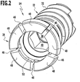
- eine perspektivische Ansicht eines proximalen Endes einer Knochenschraube aus
Figur 1 vor dem Einsetzen eines Sicherungselements; - Figur 3:
- eine teilweise geschnittene Seitenansicht eines proximalen Endes einer Knochenschraube aus
Figur 1 in der Eingriffsstellung; - Figur 4:
- eine teilweise geschnittene Seitenansicht der Knochenschraube mit dem Sicherungselement in der Eingriffsstellung;
- Figur 5:
- eine Ansicht ähnlich
Figur 4 , wobei die Knochenschraube die Lösestellung einnimmt; - Figur 6:
- eine teilweise geschnittene Seitenansicht durch ein zweites Ausführungsbeispiel einer Knochenschraube in der Lösestellung; und
- Figur 7:
- eine Ansicht ähnlich
Figur 6 eines dritten Ausführungsbeispiels einer Knochenschraube. - In
Figur 1 ist ein insgesamt mit dem Bezugszeichen 10 versehenes Implantatsystem umfassend eine Knochenplatte 12 und zwei selbstverriegelnde Knochenschrauben 14 dargestellt. - Die in
Figur 1 dargestellte Knochenplatte 12 dient in erster Linie der Illustration, sie stellt keine Beschränkung der vorliegenden Erfindung dar. Grundsätzlich wären alle Arten von Knochenplatten im Zusammenhang mit der vorliegenden Erfindung denkbar, die zumindest eine Durchbrechung für eine Knochenschraube aufweisen. - Die Knochenplatte 12 weist eine flache, kleeblattartige Form auf mit allseits abgerundeten Außenkanten. Etwa mittig ist eine nutartige Vertiefung 16 vorgesehen, die quasi jeweils zwei Blattpaare der Knochenplatte 12 voneinander trennt. Insgesamt ist die Knochenplatte 12 einstückig ausgebildet. Im Bereich jeder Ecke der Knochenplatte 12 ist eine langlochartige Durchbrechung 18 vorgesehen, wobei Längsrichtungen der Durchbrechungen 18 im wesentlichen parallel zueinander ausgerichtet sind. Eine maximale Erstreckung der Durchbrechungen 18 ist quer zur Längsrichtung der Vertiefung 16 orientiert, so daß eine minimale innere Abmessung der Durchbrechungen 18 im wesentlichen parallel zur Längsrichtung der Vertiefung 16 vorgegeben ist. Innenränder 20 der Durchbrechungen 18 sind in Richtung auf ein Zentrum der jeweiligen Durchbrechung 18 hin konkav gekrümmt, so daß sowohl an der Ober- als auch an der Unterseite der Knochenplatte 12 die Durchbrechung 18 begrenzende Ränder radial nach innen vorstehen. Die Durchbrechungen 18 bilden so mit ihren konkaven Rändern 20 im wesentlichen hohlkalottenförmige Hinterschneidungen an der Knochenplatte 20.
- Zum Festlegen der Knochenplatte 12 an nicht dargestellten Knochenteilen dienen die Knochenschrauben 14, die in Form eines ersten Ausführungsbeispiels im Zusammenhang mit den
Figuren 1 bis 5 nachfolgend näher erläutert werden. - Die Knochenschraube 14 ist im wesentlichen dreiteilig ausgebildet. Sie umfaßt einen Schaft 22, welcher eine Längsachse 23, distalseitig eine Schraubenspitze 24 und proximalseitig einen Schraubenkopf 26 definiert, sowie ein Sicherungselement in Form eines Verriegelungspins 28 und einer als Halteelement dienenden Schraubenfeder 30. Der Schaft 22 ist ausgehend von seiner Schraubenspitze 24 über etwa dreiviertel seiner Länge mit einem Außengewinde 32 versehen, welches vorzugsweise selbstschneidend ausgebildet ist. Eine Außenkontur oder Einhüllende des Schraubenkopfes 26 ist im wesentlichen kalottenförmig ausgebildet und an die durch den Innenrand 20 gebildete Hinterschneidung der Durchbrechung 18 angepaßt, wodurch eine polyaxiale Anpassung des Schraubenkopfes 26 in der hinterschnittenen Durchbrechung 18 ermöglicht wird.
- Ausgehend von seinem proximalen Ende ist der Schaft 22 mit einem eine Sicherungselementaufnahme bildenden Sackloch 34 versehen, dessen distalseitiger Boden 36 in Richtung auf das proximale Ende der Knochenschraube 14 hin weist. Ausgehend vom Boden 36 erstreckt sich auf etwa einem Drittel der Gesamtlänge des Sacklochs 34 ein Hohlzylinderabschnitt 38, in welchen die Schraubenfeder 30 eingesetzt ist, die sich mit ihrem distalseitgen Ende am Boden 36 abstützt. An den Hohlzylinderabschnitt 38 schließt sich ein Innensechskantabschnitt 40 an, welcher in etwa ein mittleres Drittel des Sacklochs 34 bildet. Der Innendurchmesser des Hohlzylinderabschnitts 38 ist etwas kleiner als eine Innenabmessung des Innensechskantabschnitts 40, so daß im Übergangsbereich zwischen dem Hohlzylinderabschnitt 38 und dem Innensechskantabschnitt 40 ein distaler, durch eine in proximaler Richtung weisende Ringfläche gebildeter Anschlag 42 gebildet wird.
- In etwa das proximale Drittel des Schafts 22 bildet den Schraubenkopf 26, welcher einen gegenüber den mit dem Außengewinde 32 versehenen Schaftabschnitt vergrößerten Außendurchmesser aufweist. Auf einer Außenseite ist der Schraubenkopf 26 mit einer umlaufenden Ringnut 44 versehen. Um den Schraubenkopf 26 in seinem Außendurchmesser variieren zu können, ist er symmetrisch über seinen Umfang mit fünf sich parallel zur Längsachse 23 erstreckenden Schlitzen 46 versehen, so daß insgesamt fünf, Verriegelungselemente bildende Segmente 48 des Schraubenskopfs 26 ausgebildet werden. Die Segmente 48 bilden lappenartige Hülsenabschnitte, welche in radialer Richtung, also in Richtung auf die Längsachse 23 hin oder von dieser weg, verschwenkbar sind. Eine gewünschte Verschwenkbarkeit kann über die Tiefe der Ringnut 44 eingestellt werden, die eine Schwächung bildet und eine Beweglichkeit der Segmente 48 erleichtert. Eine Öffnung 50 des Sacklochs 34 ist mit einem radial nach innen auf die Längsachse 23 hin vorstehenden Ringflansch 52 versehen, welcher ebenso wie die Ringnut 44 durch die Schlitze 46 unterbrochen ist. Der Ringflansch 52 bildet eine Innendurchmesserverengung des Sacklochs 34. Ferner weist er eine in distaler Richtung weisende ringförmige Anschlagfläche 54 auf, welche einen proximalseitigen, in distaler Richtung wirkenden Anschlag bildet.
- Ausgehend vom Innensechskantabschnitt 40 erweitert sich ein Innendurchmesser des Sacklochs 34 bis auf einen maximalen Innendurchmesser hin, welcher sich innen im Bereich der Ringnut 44 bis an die Anschlagfläche 54 hin erstreckt.
- Der Verriegelungspin 28 ist insgesamt in Form eines Kopfbolzens mit einem Kopf 56 und einem in Form eines zum Innensechskantabschnitt 40 korrespondierenden, in Form eines Außensechskants ausgebildeten Bolzenschaft 58 geformt. Der im Außendurchmesser gegenüber dem Bolzenschaft 58 größere Kopf 56 weist eine sich in Umfangsrichtung erstreckende, radial nach außen abstehende Schnapplippe 60 auf, welche eine ringförmige Anschlagfläche 62 umfaßt, die in proximaler Richtung weist und eine sich vom äußeren Rand der Anschlagfläche 62 in distaler Richtung erstreckende, sich konisch verjüngende Aufgleitfläche 64.
- Am Kopf ist eine in proximaler Richtung weisende, sacklochartige, sternförmige Vertiefung vorgesehen, welche als Werkzeugaufnahme 66 dient zur Aufnahme einer korrespondierenden Werkzeugspitze eines Einschraubwerkzeugs 70, dessen distales Ende in den
Figuren 4 und5 dargestellt ist. - Zum Zusammensetzen der dreiteiligen Knochenschraube 14 wird wie folgt vorgegangen. Zuerst wird die Schraubenfeder 30 durch die Öffnung 50 hindurch in das Sackloch 34 eingeführt, bis ein distales Ende der Schraubenfeder 30 am Boden 36 anliegt. Als nächstes wird der Verriegelungspin 28 mit seinem Bolzenschaft durch die Öffnung 50 hindurchgesteckt, bis der Ringflansch 52 an der Aufgleitfläche 64 anschlägt. Zum vollständigen Einführen des Verriegelungspins 28 in das Sackloch 34 müssen nun die Segmente 48 radial nach außen aufgespreizt werden. Dies geschieht durch Kraftausübung auf den Verriegelungspin 28 in distaler Richtung. Der Ringflansch 52 an den Segmenten 48 gleitet dann an der Aufgleitfläche 64 auf, so daß die Segmente 48 radial nach außen verschwenkt werden und hinter die Schnapplippe 60 radial nach innen zurückfedern, sobald die Anschlagfläche 62 die Anschlagfläche 54 am Ringflansch 52 hintergreift. Ein proximales Ende der Schraubenfeder 30 liegt am distalen Ende des Bolzenschafts 58 an und drückt den Verriegelungspin 48 in proximaler Richtung und hält so die Anschlagflächen 54 und 62 gegeneinander in Anlage. Die Knochenschraube 14 nimmt dann, wie in den
Figuren 1 ,3 und4 dargestellt, ihre Eingriffsstellung ein. - Zum Einschrauben der Knochenschraube 14 in ein nicht dargestelltes Knochenteil und zum Sichern der Knochenplatte 12 an derselben wird die Knochenschraube 14 mit Ihrem mit dem Außengewinde 32 versehenen Schaft 22 zunächst durch die Durchbrechung 18 hindurchgesteckt. Greift die Werkzeugspitze 68 in die Werkzeugaufnahme 66 ein, so wird der Verriegelungspin 28 entgegen der Federkraft der Schraubenfeder 30 in distaler Richtung bewegt, bis das distale Ende des Bolzenschafts 58 am Anschlag 42 anschlägt. Der Verriegelungspin 28 nimmt dann die in
Figur 5 dargestellte Entsicherungsstellung ein. - Durch die drehformschlüssige Ausbildung des Innensechskantabschnitts 40 und des Bolzenschafts 58 kann ein von der Werkzeugspitze 68 in den Kopf 56 eingeleitetes Drehmoment auf den Schaft 22 der Knochenschraube 14 übertragen werden. Die Knochenschraube 14 kann immer tiefer in das Knochenteil eingeschraubt werden, und zwar soweit, bis der Schraubenkopf 26 mit den verschwenkbaren Segmenten 48 am oberen ringförmigen Rand der Durchbrechung 18 anschlägt. Die Segmente 48 gleiten beim weiteren Einschrauben der Knochenschraube 14 am oberen Rand auf und werden radial nach innen verschwenkt, bis ein proximales Ende der Knochenschraube 14, also der Schraubkopf 26, ganz in die hinterschnittene Durchbrechung 18 eintauchen kann. Dann federn die Segmente 48 radial nach außen zurück und nehmen wieder ihre Eingriffsstellung ein. Der Schraubenkopf 26 ist so in der hinterschnittenen Durchbrechung 18 gehalten, aber noch nicht gesichert.
- Das Eintauchen des Schraubenkopfes 26 in die hinterschnittene Durchbrechung 18 ist nur möglich, wenn der Verriegelungspin 28 die in
Figur 5 dargestellte Entsicherungsstellung einnimmt. Sitzt die Knochenschraube 14 in gewünschter Weise im Knochen, entfernt ein Operateur das Einschraubwerkzeug 70. Durch die von der Schraubenfeder 30 ausgeübte Rückstellkraft auf den Verriegelungspin 28 wird dieser in proximaler Richtung bewegt, bis die Anschlagfläche 62 der Schnapplippe 60 wieder an der Anschlagfläche 54 anschlägt. Der Kopf 56 des Verriegelungspins 28 sitzt dann bündig zwischen den Segmenten 48 und bildet einen flachen, proximalseitigen Abschluß der Knochenschraube 14. - Ohne Einwirkung äußerer Kräfte nimmt die Knochenschraube 14 die Eingriffsstellung ein und wird durch den mittels der Schraubenfeder 30 in der Sicherungsstellung gehaltenen Verriegelungspin 28 in der Eingriffsstellung gesichert.
- In
Figur 6 ist eine insgesamt mit dem Bezugszeichen 14' versehene zweite Ausführungsform einer Knochenschraube dargestellt. Die Knochenschraube 14' unterscheidet sich von der in denFiguren 1 bis 5 dargestellten Knochenschraube 14 dadurch, daß anstelle der Schraubenfeder 30 ein insgesamt elf Tellerfedern 72' umfassendes Tellerfedernpaket 74' vorgesehen ist, welches sich distalseitig am Boden 36' und proximalseitig am distalen Ende des Bolzenschafts 58' abstützt. Alle übrigen Teile und Elemente der Knochenschraube 14' stimmen mit denen der Knochenschraube 14 überein, so daß dieselben Teile auch mit denselben Bezugsziffern versehen sind, dieFigur 6 jedoch zusätzlich einen hochgestellten Strich (') tragen. Die Funktionsweise der Knochenschraube 14' entspricht in vollem Umfang der im Zusammenhang mit den Figuren 1 bis 5 beschriebenen Knochenschraube 14. - Ein drittes Ausführungsbeispiel einer insgesamt mit dem Bezugszeichen 14" versehenen Knochenschraube ist in
Figur 7 dargestellt. Anstelle der Schraubenfeder 30 der Knochenschraube 14 ist bei der Knochenschraube 14" ein Haltekörper 76" vorgesehen. Alle anderen Teile und Elemente der Knochenschraube 14" stimmen mit denen der Knochenschraube 14 überein, so daß identische Bezugszeichen verwendet, jedoch mit zwei zusätzlichen Strichen (") versehen sind. - Der Haltekörper 76" ist im dargestellten Ausführungsbeispiel in seinem Volumen veränderbar. Hierzu weist er eine Hülle auf, welche ein dehn- oder formänderndes Element umgibt, welches aus einem Memorymetall hergestellt ist. Durch Temperaturänderungen an der Knochenschraube dehnt sich das Element aus oder zieht sich zusammen, so daß der Verriegelungspin 28" von der in
Figur 7 dargestellten Entsicherungsstellung in die Sicherungsstellung überführt werden kann, in welcher die Anschlagflächen 54" und 62" aneinander anliegen.
Claims (38)
- Knochenschraube (14) mit einem eine Längsachse (23) definierenden Schaft (22) und mit einem Kopf (26), welcher mit einer Knochenschraubenaufnahme (18) einer Knochenplatte (12) in Eingriff bringbar ist zum lösbaren Verbinden der Knochenschraube (14) mit der Knochenplatte (12), wobei ein Sicherungselement (28) zum Sichern einer Verbindung der Knochenschraube (14) und der Knochenplatte (12) vorgesehen ist, wobei die Knochenschraube (14) von einer Eingriffsstellung, in welcher die Knochenschraube (14) an der Knochenplatte (12) gehalten ist, in eine Lösestellung bringbar ist, in welcher die Knochenschraube (14) von der Knochenplatte (12) lösbar ist, wobei das Sicherungselement (28) von einer Entsicherungsstellung, in welcher die Knochenschraube (14) in die Lösestellung bringbar ist, in eine Sicherungsstellung zum Sichern der Verbindung zwischen der Knochenschraube (14) und der Knochenplatte (12) bringbar ist, in welcher die Knochenschraube (14) die Eingriffsstellung einnimmt, wobei das Sicherungselement (28) an der Knochenschraube (14) beweglich gelagert ist und die Knochenschraube (14) in einer Grundstellung, in welcher keine äußeren Kräfte auf sie wirken, die Eingriffsstellung einnimmt, wobei der Schaft (22) eine Sicherungselementaufnahme (34) aufweist und das Sicherungselement (28) in der Sicherungselementaufnahme (34) gelagert ist, wobei nach dem Einführen des Sicherungselements (28) in die Sicherungselementaufnahme (34) das Sicherungselement (28) in axialer Richtung zwischen einem in distaler und einem in proximaler Richtung wirkenden Anschlag (42, 54) bewegbar ist und wobei das Sicherungselement (28) in der Grundstellung der Knochenschraube (14) in der Sicherungsstellung gehalten ist, dadurch gekennzeichnet, daß das Sicherungselement (28) in der Sicherungsstellung unter Vorspannung gehalten ist.
- Knochenschraube nach Anspruch 1, dadurch gekennzeichnet, daß die Knochenschraube (14) rotationssymmetrisch oder im wesentlichen rotationssymmetrisch zur Längsachse (23) ausgebildet ist.
- Knochenschraube nach einem der voranstehenden Ansprüche, dadurch gekennzeichnet, daß der Kopf (26) in der Eingriffsstellung eine maximale Außenabmessung quer zur Längsachse (23) und in der Lösestellung eine gegenüber der maximalen Außenabmessung reduzierte Außenabmessung aufweist.
- Knochenschraube nach Anspruch 3, dadurch gekennzeichnet, daß der Kopf (26) in der Eingriffsstellung einen maximalen Außendurchmesser quer zur Längsachse (23) und in der Lösestellung eine gegenüber dem maximalen Außendurchmesser reduzierten Außendurchmesser aufweist.
- Knochenschraube nach einem der voranstehenden Ansprüche, dadurch gekennzeichnet, daß der Kopf (26) ein erstes Rastelement (48) trägt, welches in der Eingriffsstellung mit einem an der Knochenplatte (12) angeordneten zweiten Rastelement (20) verrastbar ist.
- Knochenschraube nach Anspruch 5, dadurch gekennzeichnet, daß das erste Rastelement (48) eine sich in Umfangsrichtung erstreckende, radial geöffnete Ringnut oder ein sich in Umfangsrichtung erstreckender, radial nach außen abstehender Ringvorsprung ist.
- Knochenschraube nach einem der voranstehenden Ansprüche, dadurch gekennzeichnet, daß zum Halten des Sicherungselements (28) in der Sicherungsstellung mindestens ein Halteelement (30; 74'; 76") vorgesehen ist, welches sich einerseits am Schaft (22) und andererseits am Sicherungselement (28) abstützt.
- Knochenschraube nach Anspruch 7, dadurch gekennzeichnet, daß das Halteelement (30; 74') ein elastisches Element ist.
- Knochenschraube nach Anspruch 8, dadurch gekennzeichnet, daß Halteelement eine Schraubenfeder (30) oder ein Paket (74') von Tellerfedern (72') ist.
- Knochenschraube nach einem der Ansprüche 7 bis 9, dadurch gekennzeichnet, daß das Halteelement (76") derart ausgebildet ist, daß eine äußere Abmessung und/oder ein Volumen des Halteelements durch Änderung mindestens einer Zustandsgröße in einer Umgebung der Knochenschraube (14) änderbar ist.
- Knochenschraube nach Anspruch 10, dadurch gekennzeichnet, daß die mindestens eine Zustandsgröße eine Umgebungstemperatur, ein Umgebungsdruck, ein osmotischer Druck oder eine Feuchtigkeit der Umgebung ist.
- Knochenschraube nach Anspruch 11, dadurch gekennzeichnet, daß das Halteelement (76") aus einem Memorymetall hergestellt ist.
- Knochenschraube nach Anspruch 11, dadurch gekennzeichnet, daß das Halteelement (76") durch ein Fluid inflatierbar ist.
- Knochenschraube nach Anspruch 11 oder 13, dadurch gekennzeichnet, daß das Halteelement (76") einen Innenraum aufweist, welcher über eine semipermeable Membran mit einer Umgebung der Knochenschraube (14) in Fluidverbindung steht.
- Knochenschraube nach einem der voranstehenden Ansprüche, dadurch gekennzeichnet, daß das Sicherungselement (28) parallel zur Längsachse (23) verschiebbar am Schaft (22) gelagert ist.
- Knochenschraube nach einem der voranstehenden Ansprüche, dadurch gekennzeichnet, daß die Sicherungselementaufnahme ein Sackloch (34) ist.
- Knochenschraube nach einem der voranstehenden Ansprüche, dadurch gekennzeichnet, daß das Sicherungselement (28) drehformschlüssig in der Sicherungselementaufnahme (34) gehalten ist.
- Knochenschraube nach einem der voranstehenden Ansprüche, dadurch gekennzeichnet, daß das Sicherungselement (28) einen Sicherungselementabschnitt (58) aufweist, welcher in Form eines Außenvielkant ausgebildet ist, und daß die Sicherungselementaufnahme (34) einen Sicherungselementaufnahmeabschnitt (40) aufweist, welcher in Form eines zum Außenvielkant korrespondierenden Innenvielkants ausgebildet ist.
- Knochenschraube nach einem der Ansprüche 5 bis 18, dadurch gekennzeichnet, daß das erste Rastelement (44) an der Knochenschraube (14) in radialer Richtung bewegbar gelagert ist.
- Knochenschraube nach einem der voranstehenden Ansprüche, dadurch gekennzeichnet, daß der Kopf (26) eine Mehrzahl quer zur Längsachse (23) bewegbarer Verriegelungselemente (48) umfaßt, welche in der Eingriffsstellung mit der Knochenplatte (12) in Eingriff stehen.
- Knochenschraube nach Anspruch 20, dadurch gekennzeichnet, daß die Verriegelungselemente (48) das erste Rastelement tragen.
- Knochenschraube nach einem der Ansprüche 20 oder 21, dadurch gekennzeichnet, daß der Kopf (26) lappenartige, durch sich parallel zur Längsachse (23) erstreckende Schlitze (46) getrennte Wandabschnitte (48) aufweist und daß die Wandabschnitte (48) die Verriegelungselemente bilden.
- Knochenschraube nach einem der Ansprüche 20 bis 22, dadurch gekennzeichnet, daß die Verriegelungselemente (48) in der Grundstellung der Knochenschraube (14) die Eingriffsstellung einnehmen.
- Knochenschraube nach einem der Ansprüche 20 bis 23, dadurch gekennzeichnet, daß zum Einführen des Sicherungselements (28) in die Sicherungselementaufnahme (34) die Verriegelungselemente (48) von der Eingriffsstellung radial nach außen bewegbar sind.
- Knochenschraube nach einem der voranstehenden Ansprüche, dadurch gekennzeichnet, daß eine zweite Rastvorrichtung (52, 60) umfassend ein drittes und ein viertes, mit dem dritten Rastelement (60) zusammenwirkendes Rastelement (52) vorgesehen ist, daß das Sicherungselement (28) und der Kopf (26) jeweils ein Rastelement (52, 60) tragen und daß die zweite Rastvorrichtung (52, 60) eine Raststellung nach dem Einführen des Sicherungselements (28) in die Sicherungselementaufnahme (34) einnimmt.
- Knochenschraube nach Anspruch 25, dadurch gekennzeichnet, daß das dritte Rastelement (60) eine in proximaler Richtung wirkende, radial nach außen abstehende Rastnase ist und daß das vierte Rastelement (52) eine radial nach innen vorstehende, in distaler Richtung wirkende Rastkante ist.
- Knochenschraube nach Anspruch 25 oder 26, dadurch gekennzeichnet, daß die Verriegelungselemente (48) das vierte Rastelement (52) tragen.
- Knochenschraube nach einem der Ansprüche 25 bis 27, dadurch gekennzeichnet, daß das dritte oder das vierte Rastelement (52, 60) den proximalen Anschlag bilden und in der Sicherungsstellung aneinander anliegen.
- Knochenschraube nach einem der Ansprüche 25 bis 28, dadurch gekennzeichnet, daß sich an das dritte oder das vierte Rastelement (60) eine Aufgleitfläche (64) anschließt, an welcher das jeweils andere Rastelement (52) beim Einführen des Sicherungselements (28) in die Sicherungselementaufnahme (34) aufgleiten kann.
- Knochenschraube nach einem der voranstehenden Ansprüche, dadurch gekennzeichnet, daß das Sicherungselement (28) in Form eines Kopfbolzens ausgebildet ist mit einem Bolzenschaft (58) und einem Bolzenkopf (56).
- Knochenschraube nach Anspruch 30, dadurch gekennzeichnet, daß der Bolzenschaft (58) den Sicherungselementabschnitt bildet, welcher in Form eines Außenvielkant ausgebildet ist.
- Knochenschraube nach einem der Ansprüche 30 oder 31, soweit diese direkt oder indirekt auf Anspruch 25 rückbezogen sind, dadurch gekennzeichnet, daß der Bolzenkopf (56) das dritte Rastelement (60) trägt.
- Knochenschraube nach einem der voranstehenden Ansprüche, dadurch gekennzeichnet, daß die Knochenschraube (14) einen Werkzeugelementadapter (66) aufweist, welcher mit einem Einschraubwerkzeug (70) zum Einschrauben der Knochenschraube (14) in Eingriff bringbar ist.
- Knochenschraube nach Anspruch 33, dadurch gekennzeichnet, daß das Sicherungselement (28) den Werkzeugadapter (66) trägt.
- Knochenschraube nach einem der Ansprüche 33 oder 34, dadurch gekennzeichnet, daß der Werkzeugadapter (66) eine Ausnehmung ist, insbesondere in Form eines Schlitzes, eines Vielkants oder einer sternförmigen Vertiefung.
- Knochenschraube nach einem der voranstehenden Ansprüche, dadurch gekennzeichnet, daß der Kopf (26) und der Schaft (22) einstückig ausgebildet sind.
- Knochenschraube nach einem der voranstehenden Ansprüche, dadurch gekennzeichnet, daß der Schaft (22) mit einem Außengewinde (32) versehen ist, insbesondere mit einem selbstschneidenden Außengewinde.
- Implantatsystem (10) umfassend mindestens eine Knochenplatte (12) mit mindestens einer Knochenschraubenaufnahme (18) und mindestens eine Knochenschraube (14), welche mit der Knochenschraubenaufnahme (18) in einer Eingriffsstellung in Eingriff bringbar ist zum lösbaren Verbinden der Knochenschraube (14) mit der Knochenplatte (12), dadurch gekennzeichnet, daß die Knochenschraube (14) eine Knochenschraube (14) nach einem der voranstehenden Ansprüche ist.
Applications Claiming Priority (2)
| Application Number | Priority Date | Filing Date | Title |
|---|---|---|---|
| DE102004050040A DE102004050040A1 (de) | 2004-10-08 | 2004-10-08 | Knochenschraube |
| PCT/EP2005/010759 WO2006040063A1 (de) | 2004-10-08 | 2005-10-06 | Knochenschraube |
Publications (2)
| Publication Number | Publication Date |
|---|---|
| EP1796561A1 EP1796561A1 (de) | 2007-06-20 |
| EP1796561B1 true EP1796561B1 (de) | 2017-05-03 |
Family
ID=35385827
Family Applications (1)
| Application Number | Title | Priority Date | Filing Date |
|---|---|---|---|
| EP05796158.3A Expired - Lifetime EP1796561B1 (de) | 2004-10-08 | 2005-10-06 | Knochenschraube |
Country Status (6)
| Country | Link |
|---|---|
| US (2) | US7988714B2 (de) |
| EP (1) | EP1796561B1 (de) |
| JP (1) | JP4834670B2 (de) |
| DE (1) | DE102004050040A1 (de) |
| ES (1) | ES2635271T3 (de) |
| WO (1) | WO2006040063A1 (de) |
Families Citing this family (50)
| Publication number | Priority date | Publication date | Assignee | Title |
|---|---|---|---|---|
| US7935137B2 (en) * | 2004-12-08 | 2011-05-03 | Depuy Spine, Inc. | Locking bone screw and spinal plate system |
| US8083769B2 (en) | 2006-11-01 | 2011-12-27 | Depuy Mitek, Inc. | Wired sutures |
| US20080161929A1 (en) | 2006-12-29 | 2008-07-03 | Mccormack Bruce | Cervical distraction device |
| US8882801B2 (en) | 2007-09-14 | 2014-11-11 | Depuy Mitek, Llc | Dual thread cannulated suture anchor |
| US8702754B2 (en) | 2007-09-14 | 2014-04-22 | Depuy Mitek, Llc | Methods for anchoring suture to bone |
| WO2009089367A2 (en) | 2008-01-09 | 2009-07-16 | Providence Medical Technology, Inc. | Methods and apparatus for accessing and treating the facet joint |
| US8377132B2 (en) | 2008-01-16 | 2013-02-19 | Aesculap Implant Systems, Llc | Standalone dynamic interbody |
| US8414651B2 (en) | 2008-01-16 | 2013-04-09 | Aesculap Implant Systems, Llc | Dynamic interbody |
| US8257407B2 (en) * | 2008-04-23 | 2012-09-04 | Aryan Henry E | Bone plate system and method |
| US9381049B2 (en) | 2008-06-06 | 2016-07-05 | Providence Medical Technology, Inc. | Composite spinal facet implant with textured surfaces |
| US11224521B2 (en) | 2008-06-06 | 2022-01-18 | Providence Medical Technology, Inc. | Cervical distraction/implant delivery device |
| EP2361046B1 (de) | 2008-06-06 | 2019-04-24 | Providence Medical Technology, Inc. | Facettengelenkimplantat und einführhilfe |
| EP3412231A1 (de) | 2008-06-06 | 2018-12-12 | Providence Medical Technology, Inc. | Facettengelenkimplantat und einführhilfe |
| US8361152B2 (en) | 2008-06-06 | 2013-01-29 | Providence Medical Technology, Inc. | Facet joint implants and delivery tools |
| US8267966B2 (en) | 2008-06-06 | 2012-09-18 | Providence Medical Technology, Inc. | Facet joint implants and delivery tools |
| US9333086B2 (en) | 2008-06-06 | 2016-05-10 | Providence Medical Technology, Inc. | Spinal facet cage implant |
| US9044282B2 (en) * | 2008-06-24 | 2015-06-02 | Extremity Medical Llc | Intraosseous intramedullary fixation assembly and method of use |
| US8182539B2 (en) | 2008-10-23 | 2012-05-22 | Aesculap Implant Systems, Llc | Dynamic interbody with motion control mechanisms |
| US9987057B2 (en) * | 2009-02-13 | 2018-06-05 | Globus Medical, Inc. | Orthopedic anchor assembly |
| US9358050B2 (en) | 2011-10-14 | 2016-06-07 | Globus Medical, Inc. | Orthopedic anchor assembly |
| US8241339B2 (en) | 2009-02-13 | 2012-08-14 | Globus Medical, Inc. | Orthopedic anchor assembly |
| CA2763265A1 (en) * | 2009-05-26 | 2010-12-02 | Synthes Usa, Llc | Variable angle screw plate systems |
| DE202009011100U1 (de) | 2009-10-01 | 2011-02-17 | All-Tight Gmbh | Medizinisches Verbindungselement |
| US8500782B2 (en) | 2010-07-22 | 2013-08-06 | Aesculap Implant Systems, Llc | Semi-dynamic fixation plate system |
| US8940030B1 (en) | 2011-01-28 | 2015-01-27 | Nuvasive, Inc. | Spinal fixation system and related methods |
| USD732667S1 (en) | 2012-10-23 | 2015-06-23 | Providence Medical Technology, Inc. | Cage spinal implant |
| USD745156S1 (en) | 2012-10-23 | 2015-12-08 | Providence Medical Technology, Inc. | Spinal implant |
| US9743961B2 (en) * | 2013-06-24 | 2017-08-29 | The University Of Toledo | Bioactive fusion device |
| US20150342648A1 (en) | 2014-05-27 | 2015-12-03 | Bruce M. McCormack | Lateral mass fixation implant |
| US10201375B2 (en) | 2014-05-28 | 2019-02-12 | Providence Medical Technology, Inc. | Lateral mass fixation system |
| US10117681B2 (en) * | 2014-10-06 | 2018-11-06 | Implantable Design, Llc | Distraction plate system |
| USD841165S1 (en) | 2015-10-13 | 2019-02-19 | Providence Medical Technology, Inc. | Cervical cage |
| JP2018532492A (ja) | 2015-10-13 | 2018-11-08 | プロビデンス メディカル テクノロジー インコーポレイテッド | 脊椎関節インプラント送達装置及びシステム |
| WO2017096098A1 (en) * | 2015-12-01 | 2017-06-08 | Revivo Medical, Llc | Bone fixation apparatus with fastener securement mechanism and methods of use |
| EP3474785A4 (de) | 2016-06-28 | 2020-03-04 | Providence Medical Technology, Inc. | Wirbelsäulenimplantat und verfahren zur verwendung davon |
| USD887552S1 (en) | 2016-07-01 | 2020-06-16 | Providence Medical Technology, Inc. | Cervical cage |
| JPWO2018066158A1 (ja) * | 2016-10-05 | 2019-07-25 | 東亞合成株式会社 | 金属酸化物触媒およびその製造方法 |
| JP2020521536A (ja) | 2017-05-19 | 2020-07-27 | プロビデンス メディカル テクノロジー インコーポレイテッド | 脊椎固定アクセス及び送達システム |
| JP7125480B2 (ja) * | 2017-10-13 | 2022-08-24 | ジンマー,インコーポレイティド | 膝関節形成方法及び器械 |
| EP3501324A1 (de) * | 2017-12-21 | 2019-06-26 | The Swatch Group Research and Development Ltd | Verkleidungselement für uhr oder schmuck |
| US11648128B2 (en) | 2018-01-04 | 2023-05-16 | Providence Medical Technology, Inc. | Facet screw and delivery device |
| US12144513B2 (en) | 2018-09-21 | 2024-11-19 | Providence Medical Technology, Inc. | Vertebral joint access and decortication devices and methods of using |
| US11298244B2 (en) | 2019-01-31 | 2022-04-12 | K2M, Inc. | Interbody implants and instrumentation |
| USD933230S1 (en) | 2019-04-15 | 2021-10-12 | Providence Medical Technology, Inc. | Cervical cage |
| USD911525S1 (en) | 2019-06-21 | 2021-02-23 | Providence Medical Technology, Inc. | Spinal cage |
| US11534307B2 (en) | 2019-09-16 | 2022-12-27 | K2M, Inc. | 3D printed cervical standalone implant |
| USD945621S1 (en) | 2020-02-27 | 2022-03-08 | Providence Medical Technology, Inc. | Spinal cage |
| CN115120323A (zh) * | 2021-03-26 | 2022-09-30 | 健宝生技股份有限公司 | 骨骼锁定系统及方法 |
| USD1098431S1 (en) | 2023-02-27 | 2025-10-14 | Providence Medical Technology, Inc. | Spinal cage |
| USD1098433S1 (en) | 2023-12-28 | 2025-10-14 | Providence Medical Technology, Inc. | Spinal cage |
Citations (1)
| Publication number | Priority date | Publication date | Assignee | Title |
|---|---|---|---|---|
| US20040127904A1 (en) * | 2002-12-31 | 2004-07-01 | Konieczynski David D. | Bone plate and resilient screw system allowing bi-directional assembly |
Family Cites Families (32)
| Publication number | Priority date | Publication date | Assignee | Title |
|---|---|---|---|---|
| CH672245A5 (en) | 1987-02-02 | 1989-11-15 | Synthes Ag | Inner osteosynthesis fastener with bone screws |
| JPH02500490A (ja) | 1986-11-25 | 1990-02-22 | シンセス アクチエン ゲゼルシャフト | 骨接合装置 |
| FR2664665B1 (fr) * | 1990-07-16 | 1993-06-11 | Alcatel Radiotelephone | Dispositif permettant un assemblage demontable. |
| SE501265C2 (sv) | 1993-05-07 | 1994-12-19 | Elos Ind Ab | Anordning för att fixera ryggkotor |
| DE4400497C1 (de) | 1994-01-11 | 1995-06-01 | Fuerniss Gmbh | Knochenschraube |
| SE9402130D0 (sv) | 1994-06-17 | 1994-06-17 | Sven Olerud | Anordning samt förfarande för plattfixation av ben |
| US5681311A (en) | 1994-09-15 | 1997-10-28 | Smith & Nephew, Inc. | Osteosynthesis apparatus |
| SE509703C2 (sv) | 1995-02-07 | 1999-03-01 | Sven Olerud | Två anordningar för låsning av två implantatelement till varandra |
| DE29521456U1 (de) | 1995-12-07 | 1997-05-07 | Aesculap Ag, 78532 Tuttlingen | Orthopädisches Haltesystem |
| US5688093A (en) * | 1996-01-29 | 1997-11-18 | Bowers; Ned C. | Ejecting quick-connect fastener |
| US5713900A (en) | 1996-05-31 | 1998-02-03 | Acromed Corporation | Apparatus for retaining bone portions in a desired spatial relationship |
| DE19702201C1 (de) | 1997-01-23 | 1998-08-06 | Aesculap Ag & Co Kg | Stiftförmiges Halteelement für ein orthopädisches Haltesystem |
| FR2771280B1 (fr) | 1997-11-26 | 2001-01-26 | Albert P Alby | Dispositif de liaison vertebrale resilient |
| US5851095C1 (en) * | 1998-04-14 | 2001-10-16 | Southco | Captive screw |
| US6533786B1 (en) | 1999-10-13 | 2003-03-18 | Sdgi Holdings, Inc. | Anterior cervical plating system |
| FR2778088B1 (fr) | 1998-04-30 | 2000-09-08 | Materiel Orthopedique En Abreg | Implant anterieur notamment pour le rachis cervical |
| US5904683A (en) | 1998-07-10 | 1999-05-18 | Sulzer Spine-Tech Inc. | Anterior cervical vertebral stabilizing device |
| EP0995404A1 (de) | 1998-10-20 | 2000-04-26 | Industrias Quirurgicas De Levante | Halswirbelplatte |
| ATE286678T1 (de) | 1999-05-03 | 2005-01-15 | Medartis Ag | Verblockbare knochenplatte |
| US6261291B1 (en) | 1999-07-08 | 2001-07-17 | David J. Talaber | Orthopedic implant assembly |
| US6235033B1 (en) * | 2000-04-19 | 2001-05-22 | Synthes (Usa) | Bone fixation assembly |
| US6524238B2 (en) * | 2000-12-20 | 2003-02-25 | Synthes Usa | Universal handle and method for use |
| US6702817B2 (en) | 2001-01-19 | 2004-03-09 | Aesculap Ag & Co. Kg | Locking mechanism for a bone screw |
| US6599290B2 (en) | 2001-04-17 | 2003-07-29 | Ebi, L.P. | Anterior cervical plating system and associated method |
| US7198627B2 (en) * | 2001-09-07 | 2007-04-03 | Zimmer Spine, Inc. | Spinal fixation device and method |
| DE10152094C2 (de) | 2001-10-23 | 2003-11-27 | Biedermann Motech Gmbh | Fixationseinrichtung für Knochen |
| GB2381197A (en) | 2001-10-25 | 2003-04-30 | Corin Surgical Ltd | A surgical implant |
| US6695846B2 (en) * | 2002-03-12 | 2004-02-24 | Spinal Innovations, Llc | Bone plate and screw retaining mechanism |
| US20040030336A1 (en) | 2002-08-06 | 2004-02-12 | Khanna Rohit Kumar | Anterior cervical spine stabilization method and system |
| US20060122605A1 (en) | 2004-12-06 | 2006-06-08 | Suh Sean S | Translational plate with cover blocking system |
| WO2006069089A2 (en) | 2004-12-21 | 2006-06-29 | Packaging Service Corporation Of Kentucky | Cervical plate system |
| US20090192549A1 (en) | 2008-01-30 | 2009-07-30 | Ebi, Llc | Bone plating system |
-
2004
- 2004-10-08 DE DE102004050040A patent/DE102004050040A1/de not_active Withdrawn
-
2005
- 2005-10-06 ES ES05796158.3T patent/ES2635271T3/es not_active Expired - Lifetime
- 2005-10-06 WO PCT/EP2005/010759 patent/WO2006040063A1/de not_active Ceased
- 2005-10-06 JP JP2007535085A patent/JP4834670B2/ja not_active Expired - Fee Related
- 2005-10-06 EP EP05796158.3A patent/EP1796561B1/de not_active Expired - Lifetime
-
2007
- 2007-04-04 US US11/732,752 patent/US7988714B2/en active Active
-
2011
- 2011-06-22 US US13/166,416 patent/US8398688B2/en not_active Expired - Fee Related
Patent Citations (1)
| Publication number | Priority date | Publication date | Assignee | Title |
|---|---|---|---|---|
| US20040127904A1 (en) * | 2002-12-31 | 2004-07-01 | Konieczynski David D. | Bone plate and resilient screw system allowing bi-directional assembly |
Also Published As
| Publication number | Publication date |
|---|---|
| US20070288025A1 (en) | 2007-12-13 |
| JP4834670B2 (ja) | 2011-12-14 |
| JP2008515498A (ja) | 2008-05-15 |
| EP1796561A1 (de) | 2007-06-20 |
| ES2635271T3 (es) | 2017-10-03 |
| WO2006040063A1 (de) | 2006-04-20 |
| US20110251649A1 (en) | 2011-10-13 |
| US8398688B2 (en) | 2013-03-19 |
| DE102004050040A1 (de) | 2006-04-20 |
| US7988714B2 (en) | 2011-08-02 |
Similar Documents
| Publication | Publication Date | Title |
|---|---|---|
| DE102004050040A1 (de) | Knochenschraube | |
| EP1316295B1 (de) | Element mit einem Schaft und einem damit verbundenen Halteelement zum Verbinden mit einem Stab | |
| DE102004027881B4 (de) | Knochenschraube und Osteosynthesevorrichtung | |
| DE10164323C1 (de) | Verschlußeinrichtung zum Sichern eines stabförmigen Elements in einem mit einem Schaft verbundenen Halteelement | |
| EP1261288B1 (de) | Verbindungselement für knochen- oder wirbelstäbe | |
| DE69520105T2 (de) | Modularer intramedullarnagel | |
| DE102007042959B4 (de) | Chirurgische Halteschraube | |
| EP1105057B1 (de) | Knochenschraube | |
| EP0977529B1 (de) | Zwischenwirbelimplantat | |
| EP2114274B1 (de) | Plattenimplantat, insbesondere für die anwendung an einer wirbelsäule | |
| EP3454767B1 (de) | Medizintechnisches instrument zur provisorischen fixierung einer polyaxialen pedikelschraube | |
| EP1474051B1 (de) | Vorrichtung zur verbindung eines längsträgers mit einem knochen | |
| EP2023833B1 (de) | Implantat mit fixierelement | |
| DE29701099U1 (de) | Stiftförmiges Halteelement für ein orthopädisches Haltesystem | |
| EP1418852A1 (de) | Interspinale prothese | |
| DE102007042953A1 (de) | Orthopädisches Haltesystem | |
| EP1316294A2 (de) | Verschlusseinrichtung zum Sichern eines stabförmigen Elements in einem mit einem Schaft verbundenen Halteelement | |
| DE29819914U1 (de) | Endoskopisches Einsetzinstrumentarium | |
| EP2832308A1 (de) | Medizinisches Instrument zum Halten und Handhaben eines chirurgischen Befestigungselements und Wirbelsäulenstabilisierungssystem | |
| DE102013107498A1 (de) | Wirbelsäulenstabilisierungssystem und chirurgisches Befestigungselement für ein Wirbelsäulenstabilisierungssystem | |
| EP1446061B1 (de) | Vorrichtung zur verbindung eines längsträgers mit einem knochenfixationsmittel | |
| DE202004015912U1 (de) | Knochenschraube | |
| EP3764950B1 (de) | Implantat | |
| DE202004020818U1 (de) | Kompressionsknochenschraube | |
| DE602004012579T2 (de) | Extraktionsvorrichtung für den Einsatz eines Knochenverbindungselementes und Einsatz |
Legal Events
| Date | Code | Title | Description |
|---|---|---|---|
| PUAI | Public reference made under article 153(3) epc to a published international application that has entered the european phase |
Free format text: ORIGINAL CODE: 0009012 |
|
| 17P | Request for examination filed |
Effective date: 20070314 |
|
| AK | Designated contracting states |
Kind code of ref document: A1 Designated state(s): AT BE BG CH CY CZ DE DK EE ES FI FR GB GR HU IE IS IT LI LT LU LV MC NL PL PT RO SE SI SK TR |
|
| DAX | Request for extension of the european patent (deleted) | ||
| RAP1 | Party data changed (applicant data changed or rights of an application transferred) |
Owner name: AESCULAP AG |
|
| 17Q | First examination report despatched |
Effective date: 20100707 |
|
| GRAP | Despatch of communication of intention to grant a patent |
Free format text: ORIGINAL CODE: EPIDOSNIGR1 |
|
| GRAJ | Information related to disapproval of communication of intention to grant by the applicant or resumption of examination proceedings by the epo deleted |
Free format text: ORIGINAL CODE: EPIDOSDIGR1 |
|
| INTG | Intention to grant announced |
Effective date: 20161017 |
|
| INTC | Intention to grant announced (deleted) | ||
| GRAP | Despatch of communication of intention to grant a patent |
Free format text: ORIGINAL CODE: EPIDOSNIGR1 |
|
| INTG | Intention to grant announced |
Effective date: 20161209 |
|
| GRAS | Grant fee paid |
Free format text: ORIGINAL CODE: EPIDOSNIGR3 |
|
| GRAA | (expected) grant |
Free format text: ORIGINAL CODE: 0009210 |
|
| AK | Designated contracting states |
Kind code of ref document: B1 Designated state(s): AT BE BG CH CY CZ DE DK EE ES FI FR GB GR HU IE IS IT LI LT LU LV MC NL PL PT RO SE SI SK TR |
|
| REG | Reference to a national code |
Ref country code: GB Ref legal event code: FG4D Free format text: NOT ENGLISH |
|
| REG | Reference to a national code |
Ref country code: AT Ref legal event code: REF Ref document number: 889087 Country of ref document: AT Kind code of ref document: T Effective date: 20170515 Ref country code: CH Ref legal event code: EP |
|
| REG | Reference to a national code |
Ref country code: IE Ref legal event code: FG4D Free format text: LANGUAGE OF EP DOCUMENT: GERMAN |
|
| REG | Reference to a national code |
Ref country code: DE Ref legal event code: R096 Ref document number: 502005015579 Country of ref document: DE |
|
| REG | Reference to a national code |
Ref country code: NL Ref legal event code: MP Effective date: 20170503 |
|
| REG | Reference to a national code |
Ref country code: LT Ref legal event code: MG4D |
|
| REG | Reference to a national code |
Ref country code: ES Ref legal event code: FG2A Ref document number: 2635271 Country of ref document: ES Kind code of ref document: T3 Effective date: 20171003 |
|
| REG | Reference to a national code |
Ref country code: FR Ref legal event code: PLFP Year of fee payment: 13 |
|
| PG25 | Lapsed in a contracting state [announced via postgrant information from national office to epo] |
Ref country code: LT Free format text: LAPSE BECAUSE OF FAILURE TO SUBMIT A TRANSLATION OF THE DESCRIPTION OR TO PAY THE FEE WITHIN THE PRESCRIBED TIME-LIMIT Effective date: 20170503 Ref country code: FI Free format text: LAPSE BECAUSE OF FAILURE TO SUBMIT A TRANSLATION OF THE DESCRIPTION OR TO PAY THE FEE WITHIN THE PRESCRIBED TIME-LIMIT Effective date: 20170503 Ref country code: GR Free format text: LAPSE BECAUSE OF FAILURE TO SUBMIT A TRANSLATION OF THE DESCRIPTION OR TO PAY THE FEE WITHIN THE PRESCRIBED TIME-LIMIT Effective date: 20170804 |
|
| PG25 | Lapsed in a contracting state [announced via postgrant information from national office to epo] |
Ref country code: LV Free format text: LAPSE BECAUSE OF FAILURE TO SUBMIT A TRANSLATION OF THE DESCRIPTION OR TO PAY THE FEE WITHIN THE PRESCRIBED TIME-LIMIT Effective date: 20170503 Ref country code: IS Free format text: LAPSE BECAUSE OF FAILURE TO SUBMIT A TRANSLATION OF THE DESCRIPTION OR TO PAY THE FEE WITHIN THE PRESCRIBED TIME-LIMIT Effective date: 20170903 Ref country code: SE Free format text: LAPSE BECAUSE OF FAILURE TO SUBMIT A TRANSLATION OF THE DESCRIPTION OR TO PAY THE FEE WITHIN THE PRESCRIBED TIME-LIMIT Effective date: 20170503 Ref country code: NL Free format text: LAPSE BECAUSE OF FAILURE TO SUBMIT A TRANSLATION OF THE DESCRIPTION OR TO PAY THE FEE WITHIN THE PRESCRIBED TIME-LIMIT Effective date: 20170503 Ref country code: BG Free format text: LAPSE BECAUSE OF FAILURE TO SUBMIT A TRANSLATION OF THE DESCRIPTION OR TO PAY THE FEE WITHIN THE PRESCRIBED TIME-LIMIT Effective date: 20170803 Ref country code: PL Free format text: LAPSE BECAUSE OF FAILURE TO SUBMIT A TRANSLATION OF THE DESCRIPTION OR TO PAY THE FEE WITHIN THE PRESCRIBED TIME-LIMIT Effective date: 20170503 |
|
| PG25 | Lapsed in a contracting state [announced via postgrant information from national office to epo] |
Ref country code: RO Free format text: LAPSE BECAUSE OF FAILURE TO SUBMIT A TRANSLATION OF THE DESCRIPTION OR TO PAY THE FEE WITHIN THE PRESCRIBED TIME-LIMIT Effective date: 20170503 Ref country code: EE Free format text: LAPSE BECAUSE OF FAILURE TO SUBMIT A TRANSLATION OF THE DESCRIPTION OR TO PAY THE FEE WITHIN THE PRESCRIBED TIME-LIMIT Effective date: 20170503 Ref country code: CZ Free format text: LAPSE BECAUSE OF FAILURE TO SUBMIT A TRANSLATION OF THE DESCRIPTION OR TO PAY THE FEE WITHIN THE PRESCRIBED TIME-LIMIT Effective date: 20170503 Ref country code: DK Free format text: LAPSE BECAUSE OF FAILURE TO SUBMIT A TRANSLATION OF THE DESCRIPTION OR TO PAY THE FEE WITHIN THE PRESCRIBED TIME-LIMIT Effective date: 20170503 Ref country code: SK Free format text: LAPSE BECAUSE OF FAILURE TO SUBMIT A TRANSLATION OF THE DESCRIPTION OR TO PAY THE FEE WITHIN THE PRESCRIBED TIME-LIMIT Effective date: 20170503 |
|
| REG | Reference to a national code |
Ref country code: DE Ref legal event code: R097 Ref document number: 502005015579 Country of ref document: DE |
|
| PLBE | No opposition filed within time limit |
Free format text: ORIGINAL CODE: 0009261 |
|
| STAA | Information on the status of an ep patent application or granted ep patent |
Free format text: STATUS: NO OPPOSITION FILED WITHIN TIME LIMIT |
|
| 26N | No opposition filed |
Effective date: 20180206 |
|
| PG25 | Lapsed in a contracting state [announced via postgrant information from national office to epo] |
Ref country code: MC Free format text: LAPSE BECAUSE OF FAILURE TO SUBMIT A TRANSLATION OF THE DESCRIPTION OR TO PAY THE FEE WITHIN THE PRESCRIBED TIME-LIMIT Effective date: 20170503 Ref country code: SI Free format text: LAPSE BECAUSE OF FAILURE TO SUBMIT A TRANSLATION OF THE DESCRIPTION OR TO PAY THE FEE WITHIN THE PRESCRIBED TIME-LIMIT Effective date: 20170503 |
|
| REG | Reference to a national code |
Ref country code: CH Ref legal event code: PL |
|
| REG | Reference to a national code |
Ref country code: IE Ref legal event code: MM4A |
|
| PG25 | Lapsed in a contracting state [announced via postgrant information from national office to epo] |
Ref country code: LI Free format text: LAPSE BECAUSE OF NON-PAYMENT OF DUE FEES Effective date: 20171031 Ref country code: CH Free format text: LAPSE BECAUSE OF NON-PAYMENT OF DUE FEES Effective date: 20171031 Ref country code: LU Free format text: LAPSE BECAUSE OF NON-PAYMENT OF DUE FEES Effective date: 20171006 |
|
| REG | Reference to a national code |
Ref country code: BE Ref legal event code: MM Effective date: 20171031 |
|
| PG25 | Lapsed in a contracting state [announced via postgrant information from national office to epo] |
Ref country code: BE Free format text: LAPSE BECAUSE OF NON-PAYMENT OF DUE FEES Effective date: 20171031 |
|
| REG | Reference to a national code |
Ref country code: FR Ref legal event code: PLFP Year of fee payment: 14 |
|
| PG25 | Lapsed in a contracting state [announced via postgrant information from national office to epo] |
Ref country code: IE Free format text: LAPSE BECAUSE OF NON-PAYMENT OF DUE FEES Effective date: 20171006 |
|
| REG | Reference to a national code |
Ref country code: AT Ref legal event code: MM01 Ref document number: 889087 Country of ref document: AT Kind code of ref document: T Effective date: 20171006 |
|
| PG25 | Lapsed in a contracting state [announced via postgrant information from national office to epo] |
Ref country code: AT Free format text: LAPSE BECAUSE OF NON-PAYMENT OF DUE FEES Effective date: 20171006 |
|
| PG25 | Lapsed in a contracting state [announced via postgrant information from national office to epo] |
Ref country code: HU Free format text: LAPSE BECAUSE OF FAILURE TO SUBMIT A TRANSLATION OF THE DESCRIPTION OR TO PAY THE FEE WITHIN THE PRESCRIBED TIME-LIMIT; INVALID AB INITIO Effective date: 20051006 |
|
| PG25 | Lapsed in a contracting state [announced via postgrant information from national office to epo] |
Ref country code: CY Free format text: LAPSE BECAUSE OF NON-PAYMENT OF DUE FEES Effective date: 20170503 |
|
| PG25 | Lapsed in a contracting state [announced via postgrant information from national office to epo] |
Ref country code: TR Free format text: LAPSE BECAUSE OF FAILURE TO SUBMIT A TRANSLATION OF THE DESCRIPTION OR TO PAY THE FEE WITHIN THE PRESCRIBED TIME-LIMIT Effective date: 20170503 |
|
| PG25 | Lapsed in a contracting state [announced via postgrant information from national office to epo] |
Ref country code: PT Free format text: LAPSE BECAUSE OF FAILURE TO SUBMIT A TRANSLATION OF THE DESCRIPTION OR TO PAY THE FEE WITHIN THE PRESCRIBED TIME-LIMIT Effective date: 20170503 |
|
| P01 | Opt-out of the competence of the unified patent court (upc) registered |
Effective date: 20230731 |
|
| PGFP | Annual fee paid to national office [announced via postgrant information from national office to epo] |
Ref country code: GB Payment date: 20231025 Year of fee payment: 19 |
|
| PGFP | Annual fee paid to national office [announced via postgrant information from national office to epo] |
Ref country code: ES Payment date: 20231117 Year of fee payment: 19 |
|
| PGFP | Annual fee paid to national office [announced via postgrant information from national office to epo] |
Ref country code: IT Payment date: 20231031 Year of fee payment: 19 Ref country code: FR Payment date: 20231023 Year of fee payment: 19 Ref country code: DE Payment date: 20231018 Year of fee payment: 19 |
|
| REG | Reference to a national code |
Ref country code: DE Ref legal event code: R119 Ref document number: 502005015579 Country of ref document: DE |
|
| GBPC | Gb: european patent ceased through non-payment of renewal fee |
Effective date: 20241006 |
|
| PG25 | Lapsed in a contracting state [announced via postgrant information from national office to epo] |
Ref country code: DE Free format text: LAPSE BECAUSE OF NON-PAYMENT OF DUE FEES Effective date: 20250501 |
|
| PG25 | Lapsed in a contracting state [announced via postgrant information from national office to epo] |
Ref country code: GB Free format text: LAPSE BECAUSE OF NON-PAYMENT OF DUE FEES Effective date: 20241006 |
|
| PG25 | Lapsed in a contracting state [announced via postgrant information from national office to epo] |
Ref country code: FR Free format text: LAPSE BECAUSE OF NON-PAYMENT OF DUE FEES Effective date: 20241031 |
|
| PG25 | Lapsed in a contracting state [announced via postgrant information from national office to epo] |
Ref country code: IT Free format text: LAPSE BECAUSE OF NON-PAYMENT OF DUE FEES Effective date: 20241006 |
|
| REG | Reference to a national code |
Ref country code: ES Ref legal event code: FD2A Effective date: 20251127 |
|
| PG25 | Lapsed in a contracting state [announced via postgrant information from national office to epo] |
Ref country code: ES Free format text: LAPSE BECAUSE OF NON-PAYMENT OF DUE FEES Effective date: 20241007 |