EP1796400A1 - Thin-film optical retarders - Google Patents
Thin-film optical retarders Download PDFInfo
- Publication number
- EP1796400A1 EP1796400A1 EP06256092A EP06256092A EP1796400A1 EP 1796400 A1 EP1796400 A1 EP 1796400A1 EP 06256092 A EP06256092 A EP 06256092A EP 06256092 A EP06256092 A EP 06256092A EP 1796400 A1 EP1796400 A1 EP 1796400A1
- Authority
- EP
- European Patent Office
- Prior art keywords
- dense
- optical retarder
- deposition
- retardance
- birefringent
- Prior art date
- Legal status (The legal status is an assumption and is not a legal conclusion. Google has not performed a legal analysis and makes no representation as to the accuracy of the status listed.)
- Ceased
Links
- 230000003287 optical effect Effects 0.000 title claims abstract description 62
- 239000010409 thin film Substances 0.000 title claims description 55
- 230000008021 deposition Effects 0.000 claims abstract description 104
- 230000010287 polarization Effects 0.000 claims abstract description 43
- 230000004907 flux Effects 0.000 claims abstract description 36
- 238000000151 deposition Methods 0.000 claims description 115
- 239000000758 substrate Substances 0.000 claims description 88
- PBCFLUZVCVVTBY-UHFFFAOYSA-N tantalum pentoxide Inorganic materials O=[Ta](=O)O[Ta](=O)=O PBCFLUZVCVVTBY-UHFFFAOYSA-N 0.000 claims description 34
- 239000000463 material Substances 0.000 claims description 31
- 239000004973 liquid crystal related substance Substances 0.000 claims description 27
- 238000000034 method Methods 0.000 claims description 18
- 238000000869 ion-assisted deposition Methods 0.000 claims description 13
- 238000004519 manufacturing process Methods 0.000 claims description 13
- 230000008569 process Effects 0.000 claims description 9
- 229910044991 metal oxide Inorganic materials 0.000 claims description 6
- 150000004706 metal oxides Chemical class 0.000 claims description 6
- 230000001965 increasing effect Effects 0.000 claims description 5
- 239000010410 layer Substances 0.000 description 148
- 238000000576 coating method Methods 0.000 description 106
- 239000011248 coating agent Substances 0.000 description 91
- VYPSYNLAJGMNEJ-UHFFFAOYSA-N Silicium dioxide Chemical compound O=[Si]=O VYPSYNLAJGMNEJ-UHFFFAOYSA-N 0.000 description 49
- 238000013461 design Methods 0.000 description 23
- 239000003989 dielectric material Substances 0.000 description 22
- 229910052681 coesite Inorganic materials 0.000 description 21
- 229910052906 cristobalite Inorganic materials 0.000 description 21
- 239000000377 silicon dioxide Substances 0.000 description 21
- 229910052682 stishovite Inorganic materials 0.000 description 21
- 229910052905 tridymite Inorganic materials 0.000 description 21
- GWEVSGVZZGPLCZ-UHFFFAOYSA-N Titan oxide Chemical compound O=[Ti]=O GWEVSGVZZGPLCZ-UHFFFAOYSA-N 0.000 description 14
- 239000010408 film Substances 0.000 description 13
- MCMNRKCIXSYSNV-UHFFFAOYSA-N Zirconium dioxide Chemical compound O=[Zr]=O MCMNRKCIXSYSNV-UHFFFAOYSA-N 0.000 description 12
- 238000005137 deposition process Methods 0.000 description 10
- 239000011521 glass Substances 0.000 description 9
- 230000000694 effects Effects 0.000 description 8
- 238000004544 sputter deposition Methods 0.000 description 8
- 230000008859 change Effects 0.000 description 7
- 238000010586 diagram Methods 0.000 description 7
- 238000001704 evaporation Methods 0.000 description 7
- 230000008020 evaporation Effects 0.000 description 7
- 235000012239 silicon dioxide Nutrition 0.000 description 7
- 238000012360 testing method Methods 0.000 description 7
- 238000005259 measurement Methods 0.000 description 6
- 238000005240 physical vapour deposition Methods 0.000 description 6
- 238000009987 spinning Methods 0.000 description 6
- 239000011800 void material Substances 0.000 description 6
- -1 TiO2 Chemical class 0.000 description 5
- 239000005329 float glass Substances 0.000 description 5
- 238000001228 spectrum Methods 0.000 description 5
- BPQQTUXANYXVAA-UHFFFAOYSA-N Orthosilicate Chemical compound [O-][Si]([O-])([O-])[O-] BPQQTUXANYXVAA-UHFFFAOYSA-N 0.000 description 4
- 239000013078 crystal Substances 0.000 description 4
- 230000007613 environmental effect Effects 0.000 description 4
- 239000005350 fused silica glass Substances 0.000 description 4
- 239000011147 inorganic material Substances 0.000 description 4
- 239000002356 single layer Substances 0.000 description 4
- 239000012780 transparent material Substances 0.000 description 4
- 238000003917 TEM image Methods 0.000 description 3
- 238000013459 approach Methods 0.000 description 3
- 210000002858 crystal cell Anatomy 0.000 description 3
- 238000009826 distribution Methods 0.000 description 3
- 238000005286 illumination Methods 0.000 description 3
- 230000000873 masking effect Effects 0.000 description 3
- 229920000642 polymer Polymers 0.000 description 3
- 229920000106 Liquid crystal polymer Polymers 0.000 description 2
- 239000004977 Liquid-crystal polymers (LCPs) Substances 0.000 description 2
- XUIMIQQOPSSXEZ-UHFFFAOYSA-N Silicon Chemical compound [Si] XUIMIQQOPSSXEZ-UHFFFAOYSA-N 0.000 description 2
- 238000004364 calculation method Methods 0.000 description 2
- 238000005229 chemical vapour deposition Methods 0.000 description 2
- 230000001419 dependent effect Effects 0.000 description 2
- 238000012886 linear function Methods 0.000 description 2
- 229920006254 polymer film Polymers 0.000 description 2
- 229910052710 silicon Inorganic materials 0.000 description 2
- 239000010703 silicon Substances 0.000 description 2
- 239000004593 Epoxy Substances 0.000 description 1
- 206010037867 Rash macular Diseases 0.000 description 1
- 238000005299 abrasion Methods 0.000 description 1
- 238000000231 atomic layer deposition Methods 0.000 description 1
- 230000008033 biological extinction Effects 0.000 description 1
- 239000005352 borofloat Substances 0.000 description 1
- 239000013590 bulk material Substances 0.000 description 1
- 210000004027 cell Anatomy 0.000 description 1
- 238000012512 characterization method Methods 0.000 description 1
- 238000006243 chemical reaction Methods 0.000 description 1
- 230000003247 decreasing effect Effects 0.000 description 1
- 230000003111 delayed effect Effects 0.000 description 1
- 238000009792 diffusion process Methods 0.000 description 1
- 238000005566 electron beam evaporation Methods 0.000 description 1
- 230000001747 exhibiting effect Effects 0.000 description 1
- 238000002474 experimental method Methods 0.000 description 1
- 238000009501 film coating Methods 0.000 description 1
- 239000011888 foil Substances 0.000 description 1
- 238000010438 heat treatment Methods 0.000 description 1
- CPBQJMYROZQQJC-UHFFFAOYSA-N helium neon Chemical compound [He].[Ne] CPBQJMYROZQQJC-UHFFFAOYSA-N 0.000 description 1
- 230000001939 inductive effect Effects 0.000 description 1
- 238000003475 lamination Methods 0.000 description 1
- 239000002184 metal Substances 0.000 description 1
- 238000001000 micrograph Methods 0.000 description 1
- 238000012986 modification Methods 0.000 description 1
- 230000004048 modification Effects 0.000 description 1
- 238000012544 monitoring process Methods 0.000 description 1
- 239000000178 monomer Substances 0.000 description 1
- 239000002086 nanomaterial Substances 0.000 description 1
- 238000005457 optimization Methods 0.000 description 1
- 239000012044 organic layer Substances 0.000 description 1
- 239000011368 organic material Substances 0.000 description 1
- 238000000623 plasma-assisted chemical vapour deposition Methods 0.000 description 1
- 238000005498 polishing Methods 0.000 description 1
- 238000006116 polymerization reaction Methods 0.000 description 1
- 238000004321 preservation Methods 0.000 description 1
- 230000004044 response Effects 0.000 description 1
- 238000004088 simulation Methods 0.000 description 1
- 239000007787 solid Substances 0.000 description 1
- 238000004528 spin coating Methods 0.000 description 1
- 238000002207 thermal evaporation Methods 0.000 description 1
- 238000000427 thin-film deposition Methods 0.000 description 1
- 238000013519 translation Methods 0.000 description 1
- 238000004627 transmission electron microscopy Methods 0.000 description 1
Images


Classifications
-
- H—ELECTRICITY
- H04—ELECTRIC COMMUNICATION TECHNIQUE
- H04N—PICTORIAL COMMUNICATION, e.g. TELEVISION
- H04N9/00—Details of colour television systems
- H04N9/12—Picture reproducers
- H04N9/31—Projection devices for colour picture display, e.g. using electronic spatial light modulators [ESLM]
- H04N9/3141—Constructional details thereof
- H04N9/315—Modulator illumination systems
- H04N9/3167—Modulator illumination systems for polarizing the light beam
-
- G—PHYSICS
- G02—OPTICS
- G02B—OPTICAL ELEMENTS, SYSTEMS OR APPARATUS
- G02B5/00—Optical elements other than lenses
- G02B5/30—Polarising elements
- G02B5/3083—Birefringent or phase retarding elements
-
- G—PHYSICS
- G03—PHOTOGRAPHY; CINEMATOGRAPHY; ANALOGOUS TECHNIQUES USING WAVES OTHER THAN OPTICAL WAVES; ELECTROGRAPHY; HOLOGRAPHY
- G03B—APPARATUS OR ARRANGEMENTS FOR TAKING PHOTOGRAPHS OR FOR PROJECTING OR VIEWING THEM; APPARATUS OR ARRANGEMENTS EMPLOYING ANALOGOUS TECHNIQUES USING WAVES OTHER THAN OPTICAL WAVES; ACCESSORIES THEREFOR
- G03B21/00—Projectors or projection-type viewers; Accessories therefor
- G03B21/14—Details
- G03B21/20—Lamp housings
- G03B21/2073—Polarisers in the lamp house
-
- G—PHYSICS
- G03—PHOTOGRAPHY; CINEMATOGRAPHY; ANALOGOUS TECHNIQUES USING WAVES OTHER THAN OPTICAL WAVES; ELECTROGRAPHY; HOLOGRAPHY
- G03B—APPARATUS OR ARRANGEMENTS FOR TAKING PHOTOGRAPHS OR FOR PROJECTING OR VIEWING THEM; APPARATUS OR ARRANGEMENTS EMPLOYING ANALOGOUS TECHNIQUES USING WAVES OTHER THAN OPTICAL WAVES; ACCESSORIES THEREFOR
- G03B33/00—Colour photography, other than mere exposure or projection of a colour film
- G03B33/10—Simultaneous recording or projection
- G03B33/12—Simultaneous recording or projection using beam-splitting or beam-combining systems, e.g. dichroic mirrors
-
- H—ELECTRICITY
- H04—ELECTRIC COMMUNICATION TECHNIQUE
- H04N—PICTORIAL COMMUNICATION, e.g. TELEVISION
- H04N9/00—Details of colour television systems
- H04N9/12—Picture reproducers
- H04N9/31—Projection devices for colour picture display, e.g. using electronic spatial light modulators [ESLM]
- H04N9/3102—Projection devices for colour picture display, e.g. using electronic spatial light modulators [ESLM] using two-dimensional electronic spatial light modulators
- H04N9/3105—Projection devices for colour picture display, e.g. using electronic spatial light modulators [ESLM] using two-dimensional electronic spatial light modulators for displaying all colours simultaneously, e.g. by using two or more electronic spatial light modulators
-
- G—PHYSICS
- G02—OPTICS
- G02B—OPTICAL ELEMENTS, SYSTEMS OR APPARATUS
- G02B1/00—Optical elements characterised by the material of which they are made; Optical coatings for optical elements
- G02B1/10—Optical coatings produced by application to, or surface treatment of, optical elements
- G02B1/11—Anti-reflection coatings
- G02B1/113—Anti-reflection coatings using inorganic layer materials only
- G02B1/115—Multilayers
Definitions
- the present application relates generally to polarization control, and in particular, to thin-film optical retarders for providing birefringence in polarization-sensitive optical systems.
- Optical retarders are used to alter the relative phase of polarized light passing therethrough, and thus, are well suited for use in applications where control over the polarization is required.
- optical retarders are also used to provide polarization compensation for other optical components in a system.
- optical retarder compensators are used to introduce a phase delay in incident light to correct for phase differences between two components of polarized light introduced by other optical components in a system.
- optical retarders One particularly important application of optical retarders is providing polarization compensation for liquid crystal display (LCD) panels, wherein residual birefringence of the liquid crystal cell causes linearly polarized light to become slightly elliptical, and wherein the optical retarder maintains the linear polarization in concert with the birefringence of the liquid crystal cell.
- LCD liquid crystal display
- trim retarder compensators These compensators, which are often referred to as trim retarder compensators, have been shown to improve system contrast in numerous LCD systems.
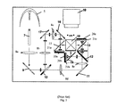
- the microdisplay system includes a light source 5, which for example is a high-pressure discharge lamp, and a light rod 7.
- the light rod 7 homogenizes the cone of light produced by the light source 5 to ensure a spatially uniform light distribution.
- the light rod 7 is a polarization conversion light pipe (PCLP) for producing linearly polarized light.
- a first lens 8a passes the light from the light pipe 7 to a first folding mirror 9, which directs the light to a first dichroic filter 10.
- the dichroic filter 10 separates out the blue light from the remaining light, and directs the blue light via second 8b and third 8c lenses, and second 17 and third 16 folding mirrors to a first LCoS display panel 20a.
- the remaining light, which is transmitted through the dichroic filter 10, is directed via fourth and fifth lenses 8d and 8e and a fourth folding mirror 11 to a second dichroic filter 12.
- the second dichroic filter 12 separates the remaining light into green and red light, the former of which is directed to a second LCoS display panel 20b and the latter of which passes to a third LCoS display panel 20c.
- each LCoS display panel 20a, 20b, 20c is a vertically aligned nematic (VAN)-mode microdisplay.
- VAN vertically aligned nematic
- Each WGP 15, 14, and 13 is a polarizer/analysisr formed from a plurality of parallel micro-wires that transmits light having a polarization orthogonal to the direction of the parallel micro-wires and reflects light having a polarization parallel to the direction of the wires (e.g., if the polarizers are designed to pass horizontal or P- polarized light, as illustrated in Fig. 1, the micro-wires will be perpendicular to the plane of Fig. 1).
- Each LCoS panel 20a, 20b, and 20c alters the polarization of the linearly polarized incident light pixel-by-pixel and reflects the modulated light back to the corresponding WGP 15, 14, and 13. Since each WGP 15, 14, and 13 is orientated at approximately ⁇ 45° with respect to the principal direction of light propagation, in addition to serving as a polarizer/analyzer, each WGP 15, 13 and 14 also serves as a beamsplitter for separating the incoming light from the outgoing light by steering or deflecting the light reflected from the each LCoS panel along an output optical path orthogonal to the incoming optical path.
- each WGP 15, 14, and 13 reflects S-polarized light (e.g., polarized light rotated by 90° by pixels in an ON state) to the X-cube 19.
- the X-cube 19 aggregates (i.e., converges) the image from each of the three color channels and, via the projection lens 18, projects the final image onto a large screen (not shown).
- each color channel further includes a pre-polarizer (not shown) and/or a clean-up analyzer (not shown), which for example, may include one or more WGPs and/or dichroic sheet polarizers.
- trim retarder compensators 21a, 21b, and 21c are compensating elements used to improve the contrast performance level of the microdisplay system, which is otherwise limited by the residual birefringence of the LCoS panels in the dark (e.g., off) state.
- each trim retarder 21a, 21b, and 21c introduces a phase retardance that cancels the retardance resulting from the inherent birefringence of the corresponding LCoS panel.
- the term 'retardance' or 'retardation' refers to linear retardance magnitude as opposed to circular retardance magnitude, unless stated otherwise.
- Linear retardance is the difference between two orthogonal indices of refraction times the thickness of the optical element.
- Linear retardance causes a phase difference between two orthogonal linear polarizations, where one polarization is aligned parallel to the extra-ordinary axis of the linear retarder and the other polarization is aligned parallel to the ordinary axis of the linear retarder.
- circular retardance causes a relative phase difference between right- and left-handed circular polarized light.
- Linear retardance may be described as either in-plane or out-of-plane retardance.
- In-plane retardance expressed as optical path length difference, refers to the difference between two orthogonal in-plane indices of refraction times the physical thickness of the optical element.
- Out-of-plane retardance refers to the difference of the index of refraction along the thickness direction (z direction) of the optical element and one in-plane index of refraction (or an average of in-plane indices of refraction), times the physical thickness of the optical element.
- Normal incidence rays in a cone bundle see only in-plane retardance, whereas off-axis rays including oblique rays (i.e.
- the P-polarized polarized light that illuminates each microdisplay panel in the dark (off) state is slightly elliptically polarized upon reflection due to the residual birefringence of the LCoS panels 20a-c.
- the elliptically polarized light which contains both a P- and an S- component, is transmitted to the corresponding WGP 15, 14, 13, the S component is reflected to the X-cube thus allowing dark state light leakage onto the large screen and limiting the contrast of the projection system.
- trim retarders 21a-c improves the contrast level by providing in-plane retardance that compensates for the retardance resulting from the residual birefringence in the LCoS panels 20a-c. More specifically, the trim retarders 21a-c are oriented such that their slow axes are configured at orthogonal azimuthal alignment to the slow axes of the LCoS panels 20a-c (termed "crossed axes"), while their fast axes are configured at orthogonal azimuthal alignment to the fast axes of the LCoS panels 20a-c.
- the terms slow axis (SA) and fast axis (FA), as used herein, refer to the two orthogonal birefringent axes when the linear retardance is measured at normal incidence. Notably, the SA and FA locations change with off-axis illumination as well as reversing the SA/FA roles for a negative out-of-plane retardance component at a large angle of incidence.
- the role of the fast/slow axes switches from the trim retarder 2 1 a-c to the LCoS panel 20a-c for normal incidence light.
- light having a specific polarization is alternately delayed more then less, or vice-versa, in the trim retarder 21a-c and the LCoS panel 20a-c, respectively.
- the net effect is zero relative delay for the incoming polarization, and as a result, an unchanged polarization (i.e., the output light is not elliptically polarized).
- the corresponding WGP 15, 14, 13 and/or optional clean-up polarizer then rejects the output light so that the dark-state panel light leakage does not appear on the screen. Since the trim retarders 21a-c do not alter significantly the throughput of the panel on-state, the resulting sequential contrast (full on/full off) is excellent.
- each trim retarder 21a-c is further illustrated in Fig. 2, with reference to the core optics of a single-channel light engine.
- These core optics include a pre-polarizer 30, a WGP 31, a trim retarder 32, a VAN-mode LCoS panel 33, and a clean-up polarizer (not shown).
- unpolarized or partial polarized light output from a prior stage illumination (not shown) is passed through the pre-polarizer 30 to obtain P-polarized light.
- the light is transmitted through the WGP 31 and its polarization extinction ratio is enhanced.
- the trim retarder 32 preconditions the incoming P-polarization beam and creates an elliptical output.
- the ellipticity in the polarized light incident onto the LCoS panel 33 which is in a dark (off) state, is undone by the residual panel retardance.
- the reflected light after completing a double pass through the VAN-LCoS panel 33 and the trim retarder 32, thus remains P-polarized.
- the remaining P-polarization component transmitted by the WGP 31 is injected back into the illumination system and is eventually lost.
- the trim retarder 32 ideally provides an in-plane retardance that matches the in-plane retardance of the corresponding LCoS panel 33 in the off-state.
- the in-plane retardance of both the LCoS panel 33 and the trim retarder 32 tends to vary within each component due to manufacturing tolerances in device thickness and material birefringence control, as well as operational drifts (temperature, mechanical stress etc).
- the in-plane retardance of both the LCoS panel 33 and the trim retarder 32 tends to vary within each component due to manufacturing tolerances in device thickness and material birefringence control, as well as operational drifts (temperature, mechanical stress etc).
- to ensure adequate compensation it is common to provide a higher in-plane retardance in the trim retarder 32 than that exhibited by the LCoS panel 33.
- this mismatch in in-plane value typically requires offsetting of the optic axis of the trim retarder 32, relative to the nominal crossed axes configuration described above.
- the trim retarder is clocked-in by rotating its azimuth orientation away from the crossed-axes configuration.
- trim retarder 32 In addition to providing in-plane retardance, it is common for the trim retarder 32 to also provide out-of-plane retardance to increase the field of view. More specifically, it is common for trim retarders to include both an A-plate compensation component for compensating the in-plane retardance and a -C-plate compensation component, which exhibits negative birefringence, for compensating for out-of plane retardance. These full function A/-C-plate trim retarders optionally also include an O-plate component.
- An A-plate is a birefringent optical element having its extraordinary axis oriented parallel to the plane of the plate.
- a C-plate is birefringent optical element having its extraordinary axis oriented perpendicular to the plane of the plate (i.e.
- An O-plate is a birefringent optical element having its extraordinary axis (i.e., its optic axis or c-axis) oriented at an oblique angle with respect to the plane of the plate.
- trim retarders have been fabricated out of stretched polymers laminated on anti-reflection (AR) coated glass substrates. More specifically, biaxially stretched polymer films, which provide a higher index of refraction along the direction of force (e.g., in the XY-plane) than along the unstretched z-direction, are used to provide full-function A/-C-plate trim retarders (i.e., in general a negative biaxial foil results).
- stretched polymer films are not ideal for many polarization-based projection systems due to a lack of retardance uniformity and environmental reliability issues. For example, with regard to the latter, the high temperature and high light flux environment provided in many microdisplay projection applications tends to make the stretched polymers relax over time, and thus lose birefringence.
- U.S. Pat. Appl. No. 20050128391 which is hereby incorporated by reference, teaches an A-plate trim retarder fabricated by spin-coating liquid crystal polymer (LCP) and linear photo-polymerization (LPP) layers on a transparent substrate. The directors of the LC monomers are aligned by the LPP layer and then cross-linked into a polymer host for solid film-like rigidity and reliability.
- LCP liquid crystal polymer
- LPP linear photo-polymerization
- the lack of a suitable -C-plate element is obviated with the introduction of a dielectric thin film form-birefringent (FB) stack into the AR coating designs (FBAR). While this full-function A/-C-plate retarder, has been shown to enhance the image contrast of VAN-mode LCoS display system from several hundreds to one to several thousands to one, it is desirable to reduce the use of organic layers in high light flux projectors applications.
- FB dielectric thin film form-birefringent
- A-plate retardance is provided by a transversely-inhomogeneous one-dimensional grating structure
- -C-plate retardance is provided by the axially-inhomogeneous one-dimensional FBAR grating structure discussed above.
- Another method of introducing form birefringence in a dielectric material is to use oblique angle deposition, wherein a thin dielectric film is deposited, either by evaporation or sputtering, at an angle, to provide a porous form-birefringent layer. More specifically, and as illustrated in Fig. 3, this technique uses oblique incident vapor flux 40 to effect atomic shadowing 42 on a substrate 44 and provide microstructures with isolated columns of material 46 growing toward the vapour source. The optical properties of the thin film are dependent on the material used, the porosity of the microstructure, and the orientation of the columns. In general, the orientation of the columns is related to the incident vapor flux angle ⁇ v (angle of incidence measured from the normal). While the incident vapor flux angle ⁇ v may be anywhere between 0° and 90°, the trend is to use high angles of incidence (e.g., greater than 75°) to maximize the tilt of the columnar microstructure.
- Gunning et al. discloses an inorganic thin film 'O-plate' compensator for improving gray scale performance in twisted nematic (TN) type LCDs.
- the optimum deposition angle, ⁇ v is reported to be 76°.
- Shimizu et al. disclose a phase retarder film containing TiO 2 that can be utilized for improving the viewing angle characteristics of a TN-type LCD or a super twisted nematic (STN) type LCD.
- the incident vapour flux angle ranges from 50° to 85°.
- the retardation compensator includes an array of rod-like columns formed by oblique angle deposition as described in U.S. Pat. No. 5,638,197 (e.g., with an optimum deposition angle of about 76°).
- the above-described porous microstructures are not ideal for projection systems.
- the layer thickness and hence the retardation uniformity will be poor.
- a high porosity is expected to cause reliability problems.
- the highly porous microstructures may delaminate from the supporting substrate in the high temperature and/or high light flux environment provided in polarization-based projection systems, such as cinematic projector.
- the porous film is expected to allow moisture to infuse into the birefringent layer(s) thereby changing its retardation property with changing humidity environment.
- trim retarders for VAN-mode reflective LCoS systems only exhibit small amounts of in-plane birefringence, to reduce back reflections and/or improve angular tuning of contrast optimization.
- trim retarders with a large in-plane retardance typically exhibit an overly sensitive tuning curve (i.e., contrast level versus clocking angle).
- the instant invention relates to optical retarders having an in-plane birefringence introduced during a thin-film deposition process that uses oblique angles to obtain a dense, form-birefringent layer.
- the dense, form-birefringent layer is deposited with an FBAR stack to provide an all-dielectric trim retarder having full functionality (i.e., both A-plate and -C-plate birefringence).
- the dense structure of the full-function trim retarder offers high durability and/or stability, thus making it well suited for providing polarization control in high light flux polarization-based projection systems.
- the magnitude of the in-plane birefringence is suitable for compensating VAN-mode LCoS microdisplay applications.
- an optical retarder comprising: at least one dense, form-birefringent layer formed using an oblique angle deposition, wherein the oblique angle and a total thickness of the at least one dense, form-birefringent layer are selected to provide an A-plate retardance for providing polarization control.
- an optical retarder comprising: depositing at least one dense, form-birefringent layer on a surface using an oblique angle deposition, wherein the oblique angle and a total thickness of the at least one dense, form-birefringent layer are selected to provide an A-plate retardance for providing polarization control.
- a liquid crystal display based projection system comprising: a light source; a first polarizer for receiving light from the light source and transmitting a first linearly polarized light having a first linear polarization axis; a liquid crystal display panel for optically modulating the first linearly polarized light, the liquid crystal display panel having residual birefringence; a second polarizer for receiving the optically modulated light and for transmitting a second linearly polarized light having a second linear polarization axis; a projection lens for projecting the second linearly polarized light onto a screen; and a trim retarder for compensating the residual birefringence of the liquid crystal display panel, the trim retarder comprising: at least one dense, form-birefringent layer formed using an oblique angle deposition, wherein the oblique angle and a total thickness of the at least one dense, form-birefringent layer are selected to provide an A-plate retardance for compensating the
- a method of providing polarization control comprising: providing at least one dense, form-birefringent layer formed using an oblique angle deposition, wherein the oblique angle and a total thickness of the at least one dense, form-birefringent layer are selected to provide an A-plate retardance for providing the polarization control.
- in-plane will be understood to describe being parallel to the plane of device, such as in-plane birefringence, in-plane retardance, in-plane retarder axis, etc.
- out-of-plane will be understood to describe being parallel to the device normal, such as out-of -plane birefringence, out-of -plane retardance, etc.
- retardation or retardance will be understood to refer to the difference between two orthogonal indices of refraction times the thickness of the optical element.
- in-plane retardation will be understood to refer to the product of the difference between two orthogonal in-plane indices of refraction times the thickness of the optical element.
- out-of-plane retardation will be understood to refer to the product of the difference of the index of refraction along the thickness direction (z direction) of the optical element and one in-plane index of refraction times the thickness of the optical element.
- this term will be understood to refer to the product of the difference of the index of refraction along the thickness direction (z direction) of the optical element and the average of in-plane indices of refraction times the thickness of the optical element.
- birefringent will be understood to refer to having multiple different indices of refraction.
- uniaxial will be understood to refer to having two different indices of refraction (e.g., where at least two of nx, ny and nz are substantially equal).
- FIG. 1 is a schematic diagram of a prior art 3-panel wire-grid polarizer (WGP) based liquid crystal on silicon (LCoS) projection light engine;
- WGP wire-grid polarizer
- LCDoS liquid crystal on silicon
- FIG. 2 illustrates the preservation of linear polarization on double passing through a LCoS panel and a trim retarder
- FIG. 3 is a schematic illustration of a glancing angle deposition (GLAD), wherein high angles of incident vapour flux are used to provide form birefringence;
- GLAD glancing angle deposition
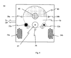
- FIG. 4 is a schematic diagram of an apparatus for fabricating a form-birefringent thin-film in accordance with one embodiment of the instant invention
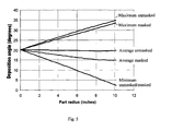
- FIG. 5 is a plot of angle of incidence as a function of radial position, for masked and unmasked configurations, calculated using the experimental set-up of the system shown in FIG. 4;
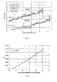
- FIG. 6 is a plot of in-plane retardance versus radial position, for masked and unmasked configurations, wherein the normal incidence retardance was measured on an Exicor at 633nm;
- FIG. 7 is a plot of in-plane retardance as a function of maximum deposition angle, for masked and unmasked configurations, calculated using FIGS. 5 and 6;
- FIG. 8 is a plot of in-plane birefringence as a function of maximum deposition angle, for the unmasked configuration, calculated using FIG. 7;
- FIG. 9 is a plot of in-plane birefringence as a function of maximum deposition angle, for the masked configuration, calculated using FIG. 7;
- FIG. 10 shows the retardance angle measured at normal incidence on the Exicor at 633 as a function of radial position
- FIG. 11 shows the measured retardance angle from FIG. 10 plotted as a function of average deposition angle at that position on the part;
- FIG. 12 shows the retardance of a red band AR coating as a function of wavelength
- FIG. 13 is a schematic diagram of an all-dielectric trim retarder, wherein A-plate retardance is provided by a dense, form-birefringent layer;
- FIG. 14 is a schematic diagram of an all-dielectric full-function A-plate/-C-plate trim retarder, wherein A-plate retardance is provided by a dense, form-birefringent layer disposed on one side of a glass substrate, and -C-plate retardance is provided by an alternating index stack disposed on an opposite side of the glass substrate;
- FIG. 15 is a schematic diagram of an all-dielectric full-function A-plate/-C-plate trim retarder, wherein A-plate retardance is provided by a dense, form-birefringent layer disposed on one side of a glass substrate, and -C-plate birefringence is provided by an alternating index stack disposed on the same side of the glass substrate;
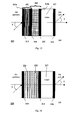
- FIG. 16 is a schematic diagram of an all-dielectric full-function A-plate/-C-plate trim retarder, wherein both the A-plate and -C-plate retardance is provided by an alternating index stack of dense, form-birefringent layers;
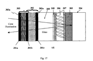
- FIG. 17 is a schematic diagram of an integrated display panel lid, incorporating an all-dielectric full-function A/-C plate trim retarder.
- birefringence in obliquely deposited thin film coatings is attributed predominantly to the columnar microstructure of the films, wherein the birefringence is dependent on the shape and direction, or tilt, of the columns.
- the column angle typically is the direction of the z-axis of the birefringent material.
- oxide materials such as TiO 2 , Ta 2 O 5 and ZrO 2 .
- the apparatus 50 which is a 48" diffusion pumped box coater, includes first 52a and second 52b crucibles for holding the material(s) to be deposited, first 54a and second 54b Calrod heaters for heating the chamber, a thermocouple 56 for monitoring the temperature of the chamber, an optical monitor 57, first 58a and second 58b crystal rate monitors, an ion-assisted deposition (IAD) source 60, a mount for supporting the substrate (or part) 70, and an optional 180° mask 80.
- the crucibles 52a/52b rotate counter-clockwise, the substrate 70 rotates counter-clockwise, and the mask 80 is fixed in position.
- the apparatus illustrated schematically in Fig. 4 was used for two different deposition procedures.
- the dense thin film was incorporated into a 4 layer AR coating.
- the dense thin film i.e., a thick Ta 2 O 5 layer
- the mask was used to minimize the maximum deposition angle and make the coating thickness uniform across the part.
- the second deposition was performed unmasked, to obtain the maximum deposition angles on the substrate, and thus, theoretically, the maximum birefringence.
- the AR was centered at 633nm, the wavelength of the helium-neon laser used to measure retardance, in order to minimize ripple in the retardance measurement caused by laser interference effects from the front and back surface of the sample when the coating reflectance is greater than about 5%.
- the total thickness of the Ta 2 O 5 layers was 2.95 ⁇ m, while the total thickness of the SiO 2 layers was 0.84 ⁇ m. It is interesting to note that because the source deposition parameters were the same for both deposition procedures, the deposition rate was about twice as fast for the unmasked as for the masked runs.
- the coating geometry was modeled for both configuration 1 and configuration 2, using a program that predicts coating thickness profiles and deposition angles based on the coating system geometry.
- the theoretical deposition angles incident on the substrate are plotted as a function of radial position.
- the minimum angles for the masked and unmasked configurations are the same. Since the substrate, or part, is rotated about its center during deposition, there is rotational symmetry to the coating thickness and the deposition angle distribution. Alternatively, the substrate is moved relative to the incident vapour flux and/or mask with a simple translation or with planetary motion (i.e., is simultaneously rotated about its center and translated along an orbital path).
- Equation (2) which predicts the column tilt, ⁇ , from the deposition angle, ⁇ ⁇ , for Ta 2 O 5 , was used as a reference to calculate column tilt. More specifically, Equation (2) was only used as a reference because it assumes that all of the source material arrives at the substrate at the same deposition angle, it does not take into account the angular distribution of the material arriving at a position on the part, and it does not take into account any effects of masking or the difference in deposition rate for the masked and unmasked coatings.
- the column tilt for the unmasked coating should be about 6.7° for the average deposition angle, and about 13° for the maximum deposition angle at the outer radius of the part. According to the aforementioned prior art plot, this would result in an in-plane birefringence of about 0.02 for the maximum deposition angle, and about 0.0075 for the average deposition angle.
- the simulations also predict that the masked coating will exhibit less birefringence than the unmasked coating near the outer radius of the part, since both the average and maximum deposition angles for the masked configuration are less than those for the unmasked.
- the retardance increased with radial position. This indicates that the retardance is influenced more by the maximum deposition angle than by the average deposition angle, because the maximum deposition angle for both masked and unmasked configurations increases with radial position as shown in Fig. 5.
- the experimental retardance is re-plotted as a function of the maximum deposition angle. This plot is shown in Fig. 7.
- the unmasked samples have about 11% total thickness variation across the inner and outer segments, with the physical thickness decreasing from the inner to the outer radial positions.
- the masked run has the same physical thickness as the unmasked run at the radial position around the 9.5" radial position, but is thicker at the lower radial positions.
- the thickness profile based on the calculated coating geometry was used to model the coating thickness, and with equation (3) was used to calculate the normal incidence, or in-plane birefringence ( ⁇ n ), for the unmasked runs as a function of maximum deposition angle.
- the L and H subscripts refer to the low refractive index material (i.e., SiO 2 ) and the high refractive index material (i.e., Ta 2 O 5 ), respectively. Since SiO 2 deposits in a substantially amorphous structure, the birefringence of this material was neglected (preliminary experimental measurements indicated it is very small).
- the in-plane birefringence of this material was calculated.
- Fig. 8 illustrates the in-plane birefringence as a function of the maximum deposition angle. The measured retardance was approximated by a linear function for this calculation over this narrow angle range.
- the masked sample had less than 1.5% thickness variation across the measured radial positions, not enough to be distinguished in the measurement ripple, so the physical thickness was assumed to be constant. Again, the birefringence of the SiO 2 was assumed to be negligible and all of the retardance was attributed to the Ta 2 O 5 layers.
- the in-plane ⁇ n of the coating was calculated from equation (3). Fig 9 is a plot of this calculated in-plane ⁇ n for the masked coatings. For this calculation, the measured retardance as a function of maximum deposition angle is approximated by a linear function.
- the samples from the masked run had a higher in-plane birefringence than the unmasked ones by about a factor of 2. This is the opposite of what one would expect from the deposition angles (i.e., since the masked configuration had lower maximum and average deposition angles than the unmasked configuration).
- the difference in birefringence for these two configurations is thus believed to be due to the difference in deposition rates, or more likely, the belief that the mask is influencing the columnar structure as it blocks the coating flux during half of the part rotation cycle.
- the birefringence of both samples was less than that predicted by the prior art plot, wherein all of the coating flux was incident at a single angle of incidence.
- the incident cone of coating flux may be "rounding" the columnar structure (reducing its directionality), so that the birefringence is less.
- the in-plane retardance of current, commercially available trim retarders for VAN-mode LCoS microdisplays is typically in the range between about 2 - 7nm.
- the amount of in-plane birefringence exhibited by Ta 2 O 5 at the outer radius of the disk, 0.0012 unmasked and 0.0023 masked, is in the appropriate range to make a trim retarder with a reasonable coating thicknesses (e.g., less than 6 ⁇ m thick).
- Fig. 10 which is a plot of this data for the masked and unmasked samples, shows that the unmasked sample had a more uniform fast axis orientation than the masked sample. More specifically, Fig. 10 shows a plot of retardance angle versus average deposition angle, wherein the retardance angle is the angle the fast axis of the birefringent material makes with respect to the x scan direction. Fig. 11 shows this same retardance plotted as a function of the calculated average deposition angle.
- TEM transmission electron microscopy
- the TEM micrographs indicated that the thin films were substantially amorphous. While some of the micrographs exhibited possible evidence of columnar microstructure, there was definitely a lack of distinct columns and/or voids. Moreover, some of the TEM micrographs exhibited speckled or blotchy regions in the thick Ta 2 O 5 layer. The speckled nanostructure, which was more pronounced for the masked runs than the unmasked runs, may be related to the unexpectedly higher in-plane birefringence of the masked run than the unmasked runs.
- a fully dense, form-birefringent thin-film is used to provide polarization control in an optical system (e.g., in a liquid crystal display system, in a polarimeter, as a quarter-waveplate, etc.).
- form birefringence is introduced into the thin-film via an oblique angle deposition.
- the deposition process which is typically a physical vapour deposition using one of a variety of evaporation or sputtering deposition techniques well known to those skilled in the art, is preferably selected and/or altered to ensure that the thin-film is dense (e.g., greater than about 90% bulk density) and exhibits adequate birefringence (e.g., greater than about 0.0002 at 550nm).
- the coating flux incident angle, the coating mask design, the coating source and substrate distance, the coating source and substrate relative positions and orientations, the deposition rate, the substrate spinning control, and the coating material is typically selected to provide the desired birefringence and/or density.
- a high density is achieved by using an energetic process, such as IAD.
- the coating flux incident angle included a broad range of deposition angles (e.g., 2 to 35°)
- the optional coating mask was a 180° mask
- the substrate was about 30" away from the crucibles
- the deposition rate was between about 2 and 12 ⁇ /sec
- the substrate was spun at about 500 rpm
- an IAD source was used.
- the average deposition angle, or more typically, the maximum deposition angle will be below about 40°.
- the dense form-birefringent thin-film is readily fabricated from normally isotropic materials (i.e., not molecularly birefringent), and in particular from inorganic and/or dielectric materials. Accordingly, the dense form-birefringent film is readily incorporated with other thin film layers to provide multi-functional all-dielectric thin film stacks.
- a dense, form-birefringent thin-film layer is incorporated into an AR coating, which is used to provide polarization compensation for a liquid crystal display.
- an AR coating which is used to provide polarization compensation for a liquid crystal display.
- a thick Ta 2 O 5 layer is incorporated into a 4 layer Ta 2 O 5 /SiO 2 AR design.
- other designs are provided.
- the red band AR coating which is about 7.5 ⁇ m thick, provides an average in-plane retardance of about 6.8nm.
- the corresponding level of birefringence is suitable for the manufacture of low retardance trim retarders for VAN-mode LCoS systems.
- the birefringence is expected to be extremely stable in the high light flux and/or high temperature environment provided by microdisplay projection systems.
- a dense, form-birefringent thin-film layer is incorporated into a stand-alone all-dielectric trim retarder, which is used to compensate for residual birefringence of a VAN-mode LCoS microdisplay projection system.
- the trim retarder 90 has a dielectric thin film stack 92 disposed on a first side of a substrate 93 and an anti-reflection coating 94 disposed on a second opposite side of the substrate 93.
- the dielectric thin film stack 92 which imparts A-plate functionality to the trim retarder 90, includes a dense, form-birefringent layer 95 bound by AR layers 96.
- Each AR layer 94, 96 which is typically a dielectric stack, serves as a refractive index matching layer at an interface with an abrupt refractive index change.
- form birefringence is introduced into the dense, form-birefringent layer 95 via an oblique angle deposition.
- the deposition process which is typically a physical vapour deposition using one of a variety of evaporation or sputtering deposition techniques well known to those skilled in the art, is preferably selected and/or altered to ensure that the thin-film is dense (e.g., greater than about 90% bulk density) and exhibits adequate birefringence (e.g., greater than about 0.0002 at 550nm).
- the coating flux incident angle, the coating mask design, the coating source and substrate distance, the coating source and substrate relative positions and orientations, the deposition rate, the substrate spinning control, and the coating material is typically selected to provide the desired birefringence and/or density.
- a high density is achieved by using an energetic process, such as IAD.
- the coating flux incident angle included a broad range of deposition angles (e.g., 2 to 35°)
- the optional coating mask was a 180° mask
- the substrate was about 30" away from the crucibles
- the deposition rate was between about 2 and 12 ⁇ /sec
- the substrate was spun at about 500 rpm
- an IAD source was used.
- the average deposition angle, or more typically, the maximum deposition angle will be below about 40°.
- the thin film stack 92 is shown to include a single, dense, form-birefringent layer 95 for exemplary purposes only.
- the thin film stack 92 includes a plurality of thinner dense, form-birefringent layers and/or intervening layers (e.g., in an alternating index design).
- the form-birefringent layer 95 is fabricated from a material with a refractive index similar to the substrate and the inner AR coating is omitted.
- the A-plate stack includes at least one dense, form-birefringent layer incorporated into a more complex AR design.
- the form-birefringent layer will be typically fairly thick (e.g., several microns).
- Suitable dielectrics for forming the dielectric thin film stack 92 and/or AR layer 94 include metal oxides such as TiO 2 , Ta 2 O 5 , ZrO 2 , and SiO 2 , which are optically isotropic and exhibit high transparency in the visible wavelength spectrum range (e.g., from 400nm to 700nm).
- the substrate 93 is typically a plane-parallel glass plate substrate, which for example, is about 1 mm thick.
- the substrate is fabricated from another transparent material that provides mechanical support, such as fused silica.
- the in-plane retardance of this trim retarder which in practice may be up to about a quarterwave, is typically targeted for less than 30nm, and more typically for between about 1 and 10nm, across the entire visible band.
- the trim retarder is targeted for 5nm of in-plane retardance, and has an effective in-plane birefringence of about 0.002
- the single layer A-plate design would require about a 2.5 ⁇ m layer.
- a film of this thickness is well within the capability of any decent coating machine.
- the A-plate birefringence is generated by the deposition process itself. Since the dense, form-birefringent layer 95 is readily deposited in standard coating chambers, in tandem with the AR coatings 94/96, a very low cost all-dielectric trim retarder is provided. Moreover, since the trim retarder is fabricated entirely from inorganic dielectric material, a highly durable and/or moisture impervious coating is obtained. Furthermore, since the inorganic dielectric material lacks distinct column/void microstructure, the birefringence is expected to be extremely stable in the high light flux and/or high temperature environment provided by microdisplay projection systems.
- the trim retarder 100 includes a -C-plate dielectric stack 101, an A-plate dielectric stack 102, and a substrate 107. More specifically, the -C-plate stack 101 is coupled to a first side of the substrate 107, while the A-plate stack 102 is coupled to a second opposite side of the substrate 107.
- the -C plate dielectric stack 101 includes a form-birefringent (FB) structure 103 bound by anti-reflection (AR) coatings 105 to provide an FBAR stack with -C-plate functionality.
- the form-birefringent structure 103 includes a first plurality of layers, each having a first refractive index n 1 and a first thickness d 1 , alternating with at least a second plurality of layers, each having a second refractive index n 2 and a second layer thickness of d 2 .
- the form birefringence will be maximized if the layer thicknesses d 1 and d 2 are similar, and if the difference between n 1 and n 2 is large (e.g., greater than about 0.5).
- n 1 and n 2 is large (e.g., greater than about 0.5).
- an -C-plate stack including 71 pairs of tantala (Ta 2 O 5 ) and silica (SiO 2 ) layers, having nominal indices of 2.20 and 1.46 at ⁇ 550nm, respectively, has been estimated to provide a net retardation of approximately -6.3nm at ⁇ 12° angle of incidence in air.
- the resulting effective index of the stack is about 2.
- the A-plate dielectric stack 102 includes a dense, form-birefringent layer 104 bound by AR layers 106.
- form birefringence is introduced into the dense, form-birefringent layer 104 via an oblique angle deposition.
- the deposition process which is typically a physical vapour deposition using one of a variety of evaporation or sputtering deposition techniques well known to those skilled in the art, is preferably selected and/or altered to ensure that the thin-film is dense (e.g., greater than about 90% bulk density) and exhibits adequate birefringence (e.g., greater than about 0.0002 at 550nm).
- the coating flux incident angle, the coating mask design, the coating source and substrate distance, the coating source and substrate relative positions and orientations, the deposition rate, the substrate spinning control, and the coating material is typically selected to provide the desired birefringence and/or density.
- a high density is achieved by using an energetic process, such as IAD.
- the coating flux incident angle included a broad range of deposition angles (e.g., 2 to 35°)
- the optional coating mask was a 180° mask
- the substrate was about 30" away from the crucibles
- the deposition rate was between about 2 and 12 ⁇ /sec
- the substrate was spun at about 500 rpm
- an IAD source was used.
- the average deposition angle, or more typically, the maximum deposition angle will be below about 40°.
- the A-plate dielectric stack 102 is shown to include a single, dense, form-birefringent layer 104 for exemplary purposes only.
- the A-plate stack 102 includes a plurality of thinner dense, form-birefringent layers and/or intervening layers (e.g., in an alternating index design).
- the form-birefringent layer 104 is fabricated from a material with a refractive index similar to the substrate and the inner AR coating is omitted.
- the A-plate stack includes at least one dense, form-birefringent layer incorporated into a more complex AR design.
- the form-birefringent layer will be typically fairly thick (e.g., several microns), whereas embodiments wherein the A-plate dielectric stack 102 includes a plurality of dense, form-birefringent layer, the form-birefringent layers will be typically relatively thin.
- each AR layer 105/106 which is typically a dielectric stack, serves as a refractive index matching layer at an interfaces with an abrupt index change.
- the AR coatings 105/106 may also provide an additional out-of-plane retardance component that should be factored in to the overall retardance and phase difference when the trim retarder is being manufactured.
- Suitable dielectrics for forming the -C-plate dielectric stack 101 and/or the A-plate dielectric stack 102 include metal oxides such as TiO 2 , Ta 2 O 5 , ZrO 2 , and SiO 2 , which are optically isotropic and exhibit high transparency in the visible wavelength spectrum range (e.g., from 400nm to 700nm).
- the substrate 107 is typically a plane-parallel glass plate substrate, which for example, is about 1 mm thick.
- the substrate is fabricated from another transparent material that provides mechanical support, such as fused silica.
- the in-plane retardance of this trim retarder which in practice may be up to about a quarterwave, is typically targeted for less than 30nm, and more typically for between about 1 and 10nm across the entire visible band.
- the trim retarder is targeted for 5nm of in-plane retardance, and has an effective in-plane birefringence of about 0.002
- the single layer A-plate design would require about a 2.5 ⁇ m layer.
- a film of this thickness is well within the capability of any decent coating machine.
- the out-of-plane retardance of this trim retarder is typically targeted in the range from about -1nm to about-1000nm, across the entire visible band.
- both the A-plate retardance and the -C-plate retardance are provided by inorganic and/or dielectric materials. Accordingly, both the A-plate stack and -C-plate stack are readily deposited in standard coating chambers, to provide a low cost all-dielectric trim retarder. Moreover, since the full-function trim retarder is fabricated entirely from inorganic dielectric material, a highly durable and/or moisture impervious coating is obtained. Furthermore, since the inorganic dielectric material lacks distinct column/void microstructure, the birefringence is expected to be extremely stable in the high light flux and/or high temperature environment provided by microdisplay projection systems.
- the trim retarder 110 includes a -C-plate dielectric stack 111, a A-plate dielectric stack 112, a plurality of AR layers 113, 114, 115, and 116, and a substrate 117. More specifically, both the -C-plate dielectric stack 111 and the A-plate dielectric stack 112 are coupled to a first side of the substrate 117, while an AR layer 116 is coupled to a second opposite side of the substrate 117.
- the -C plate dielectric stack 111 includes a form-birefringent (FB) structure 111a bound by anti-reflection (AR) coatings 113/114 to provide an FBAR stack with -C-plate functionality.
- the form-birefringent structure 111a includes a first plurality of layers, each having a first refractive index n 1 and a first thickness d 1 , alternating with at least a second plurality of layers, each having a second refractive index n 2 and a second layer thickness of d 2 .
- the form birefringence will be maximized if the layer thicknesses d 1 and d 2 are similar, and if the difference between n 1 and n 2 is large (e.g., greater than about 0.5).
- n 1 and n 2 is large (e.g., greater than about 0.5).
- an -C-plate stack including 71 pairs of tantala (Ta 2 O 5 ) and silica (SiO 2 ) layers, having nominal indices of 2.20 and 1.46 at ⁇ 550nm, respectively, has been estimated to provide a net retardation of approximately -6.3nm at ⁇ 12° angle of incidence in air.
- the resulting effective index of the stack is about 2.
- the A-plate dielectric stack 112 includes a dense, form-birefringent layer 112a bound by AR layers 114/115.
- form birefringence is introduced into the dense, form-birefringent layer 112a via an oblique angle deposition.
- the deposition process which is typically a physical vapour deposition using one of a variety of evaporation or sputtering deposition techniques well known to those skilled in the art, is preferably selected and/or altered to ensure that the thin-film is dense (e.g., greater than about 90% bulk density) and exhibits adequate birefringence (e.g., greater than about 0.0002 at 550nm).
- the coating flux incident angle, the coating mask design, the coating source and substrate distance, the coating source and substrate relative positions and orientations, the deposition rate, the substrate spinning control, and the coating material is typically selected to provide the desired birefringence and/or density.
- a high density is achieved by using an energetic process, such as IAD.
- the coating flux incident angle included a broad range of deposition angles (e.g., 2 to 35°)
- the optional coating mask was a 180° mask
- the substrate was about 30" away from the crucibles
- the deposition rate was between about 2 and 12 ⁇ /sec
- the substrate was spun at about 500 rpm
- an IAD source was used.
- the average deposition angle, or more typically, the maximum deposition angle will be below about 40°.
- the A-plate dielectric stack 112 is shown to include a single, dense, form-birefringent layer 112a for exemplary purposes only.
- the A-plate stack includes a plurality of thinner dense, form-birefringent layers and/or intervening layers (e.g., in an alternating index design).
- the form-birefringent layer is fabricated from a material with a refractive index similar to the substrate and the inner AR coating 115 is omitted.
- the A-plate stack includes at least one dense, form-birefringent layer incorporated into a more complex AR design.
- the form-birefringent layer will be typically fairly thick (e.g., several microns), whereas embodiments wherein the A-plate dielectric stack is replaced with a plurality of dense, form-birefringent layer, the form-birefringent layers will be typically relatively thin.
- Each of the AR layers 113, 114, 115, and 116 which is typically a dielectric stack, serves as refractive index matching layer at an interface with an abrupt index change.
- the AR coatings 113, 114, 115, and 116 may also provide an additional out-of-plane retardance component that should be factored in to the overall retardance and phase difference when the trim retarder is being manufactured.
- Suitable dielectrics for forming the -C-plate dielectric stack 111 and/or the A-plate dielectric stack 112 include metal oxides such as TiO 2 , Ta 2 O 5 , ZrO 2 and SiO 2 which are optically isotropic and exhibit high transparency in the visible wavelength spectrum range (e.g., from 400nm to 700nm).
- the substrate 117 is typically a plane-parallel glass plate substrate, which for example, is about 1 mm thick.
- the substrate is fabricated from another transparent material that provides mechanical support, such as fused silica.
- the in-plane retardance of this trim retarder which in practice may be up to about a quarterwave, is typically targeted for less than 30nm, and more typically for between about 1 and 10nm, across the entire visible band.
- the trim retarder is targeted for 5nm of in-plane retardance, and has an effective in-plane birefringence of about 0.002
- the single layer A-plate design would require about a 2.5 ⁇ m layer.
- a film of this thickness is well within the capability of any decent coating machine.
- the out-of-plane retardance of this trim retarder is typically targeted in the range from about -1nm to about -1000nm, across the entire visible band.
- both the A-plate retardance and the -C-plate retardance are provided by inorganic and/or dielectric materials. Accordingly, both the A-plate stack and -C-plate stack are readily deposited in standard coating chambers, to provide a low cost all-dielectric trim retarder. Moreover, since the full-function trim retarder is fabricated entirely from inorganic dielectric material, a highly durable and/or moisture impervious coating is obtained. Furthermore, since the inorganic dielectric material lacks distinct column/void microstructure, the birefringence is expected to be extremely stable in the high light flux and/or high temperature environment provided by microdisplay projection systems.
- the -C-plate dielectric stack 111 is cascaded onto the dense A-plate dielectric stack.
- the A-plate dielectric stack is cascaded onto the-C-plate dielectric stack 111.
- the trim retarder 210 includes a dielectric stack having a first plurality of high-refractive index layers 211, alternating with a second plurality of low-refractive index layers 212, and bound by AR layers 214, 215.
- the dielectric stack is coupled to one side of the substrate 217, while another AR layer 216 is coupled to a second opposite side of the substrate 217.
- the layer thickness of each of the first and second plurality of layers is selected such that the dielectric stack provides -C-plate functionality. At least one of the first and second plurality of layers is formed with an oblique angle deposition.
- the deposition process which is typically a physical vapour deposition using one of a variety of evaporation or sputtering deposition techniques well known to those skilled in the art, is preferably selected and/or altered to ensure that the dielectric stack is dense (e.g., greater than about 90% bulk density) and exhibits adequate A-plate birefringence (e.g., greater than about 0.0002 at 550nm).
- the layer thickness will be typically below about 100nm, and often less than about 20nm, to provide the appropriate -C-plate birefringence, a higher angle of incidence may be required to provide a higher A-plate retardance, thus requiring an adjustment to at least one of the deposition rate, the substrate spinning control, and the energetic process, to ensure that the microstructure is non-porous.
- Each of the AR layers 214, 215, and 216 which is typically a dielectric stack, serves as refractive index matching layer at an interface with an abrupt index change.
- the AR coatings may also provide an additional out-of-plane retardance component that should be factored in to the overall retardance and phase difference when the trim retarder is being manufactured.
- Suitable dielectrics for forming the dielectric stack include metal oxides such as TiO 2 Ta 2 O 5 , ZrO 2 , and SiO 2 which are optically isotropic and exhibit high transparency in the visible wavelength spectrum range (e.g., from 400nm to 700nm).
- the substrate 217 is typically a plane-parallel glass plate substrate, which for example, is about 1 mm thick.
- the substrate is fabricated from another transparent material that provides mechanical support, such as fused silica.
- the in-plane retardance of this trim retarder which in practice may be up to about a quarterwave, is typically targeted for less than 30nm, and more typically for between about 1 and 10nm, across the entire visible band.
- the out-of-plane retardance of this trim retarder is typically targeted in the range from about -1nm to about -1000nm, across the entire visible band.
- both the A-plate retardance and the -C-plate retardance are provided by the same inorganic dielectric materials, thus simplifying the deposition procedure.
- the full-function trim retarder is fabricated entirely from inorganic dielectric material, a highly durable and/or moisture impervious coating is obtained.
- the inorganic dielectric material lacks distinct column/void microstructure, the birefringence is expected to be extremely stable in the high light flux and/or high temperature environment provided by microdisplay projection systems.
- a dense, form-birefringent thin-film layer is incorporated into an all-dielectric trim retarder integrated with another optical component, which is used to compensate for residual birefringence of a VAN-mode LCoS microdisplay projection system.
- the trim retarder subassembly includes a -C-plate dielectric stack 303, an A-plate dielectric stack 302, and a plurality of AR layers 301, all disposed on a first surface of a transparent cover substrate 300.
- This trim retarder subassembly forms an LC cell gap, in which LC molecules 306 are disposed, with the top-level metal reflectors 305 disposed on the silicon backplane (substrate) 304.
- the LCoS also includes alignment layers (e.g., polymeric or obliquely evaporated inorganic layers) 307 and a front transparent conductive electrode (e.g., ITO) 308.
- the -C plate dielectric stack 303 includes a form-birefringent (FB) structure 303a bound by anti-reflection (AR) coatings 301a/b to provide an FBAR stack with -C-plate functionality.
- the form-birefringent structure 303a includes a first plurality of layers, each having a first refractive index n 1 and a first thickness d 1 , alternating with at least a second plurality of layers, each having a second refractive index n 2 and a second layer thickness of d 2 .
- the form birefringence will be maximized if the layer thicknesses d 1 and d 2 are similar, and if the difference between n 1 and n 2 is large (e.g., greater than about 0.5).
- n 1 and n 2 is large (e.g., greater than about 0.5).
- an -C-plate stack including 71 pairs of tantala (Ta 2 O 5 ) and silica (SiO 2 ) layers, having nominal indices of 2.20 and 1.46 at ⁇ 550nm, respectively, has been estimated to provide a net retardation of approximately -6.3nm at ⁇ 12° angle of incidence in air.
- the resulting effective index of the stack is about 2.
- the A-plate dielectric stack 302 includes a dense, form-birefringent layer 302a bound by AR layers 301b/c.
- form birefringence is introduced into the dense, form-birefringent layer 302a via an oblique angle deposition.
- the deposition process which is typically a physical vapour deposition using one of a variety of evaporation or sputtering deposition techniques well known to those skilled in the art, is preferably selected and/or altered to ensure that the thin-film is dense (e.g., greater than about 90% bulk density) and exhibits adequate birefringence (e.g., greater than about 0.0002 at 550nm).
- the coating flux incident angle, the coating mask design, the coating source and substrate distance, the coating source and substrate relative positions and orientations, the deposition rate, the substrate spinning control, and the coating material is typically selected to provide the desired birefringence and/or density.
- a high density is achieved by using an energetic process, such as IAD.
- the coating flux incident angle included a broad range of deposition angles (e.g., 2 to 35°)
- the optional coating mask was a 180° mask
- the substrate was about 30" away from the crucibles
- the deposition rate was between about 2 and 12 ⁇ /sec
- the substrate was spun at about 500 rpm
- an IAD source was used.
- the average deposition angle, or more typically, the maximum deposition angle will be below about 40°.
- the A-plate dielectric stack 302 is shown to include a single, dense, form-birefringent layer for exemplary purposes only.
- the A-plate stack includes a plurality of thinner dense, form-birefringent layers and/or intervening layers (e.g., in an alternating index design).
- the dense, form-birefringent layer is fabricated from a material with a refractive index similar to the substrate and the inner AR coating 301c is omitted.
- the A-plate stack includes at least one dense, form-birefringent layer incorporated into a more complex AR design.
- the form-birefringent layer will be typically fairly thick (e.g., several microns), whereas embodiments wherein the A-plate dielectric stack 112 is replaced with a plurality of dense, form-birefringent layer, the form-birefringent layers will be typically relatively thin.
- Each of the AR layers 301a-c which is typically a dielectric stack, serves as refractive index matching layer at an interface with an abrupt index change.
- the AR coatings 301a-c may also provide an additional out-of-plane retardance component that should be factored in to the overall retardance and phase difference when the trim retarder is being manufactured.
- Suitable dielectrics for forming the -C-plate dielectric stack 303 and/or the A-plate dielectric stack 302 include metal oxides such as TiO 2 Ta 2 O 5 , ZrO 2 and SiO 2 , which are optically isotropic and exhibit high transparency in the visible wavelength spectrum range (e.g., from 400nm to 700nm).
- the in-plane retardance of this trim retarder which in practice may be up to about a quarterwave, is typically targeted for less than 30nm, and more typically for between about 1 and 10nm, across the entire visible band.
- the trim retarder is targeted for 5nm of in-plane retardance, and has an effective in-plane birefringence of about 0.002
- the single layer A-plate design would require about a 2.5 ⁇ m layer.
- a film of this thickness is well within the capability of any decent coating machine.
- the out-of-plane retardance of this trim retarder is typically targeted in the range from about -1nm to about -1000nm, across the entire visible band.
- the coarse azimuthal angle offset between the A-plate/-C-plate stacks and the display element 306 may be imposed by mechanically rotating the cover substrate in the plane of the device, having considered the nominal in-plane retardance magnitudes of the two retarder elements.
- Individual fine-tuning of each integrated compensator/display may involve other non-mechanical means, such as voltage-switching the LC tilt angles in the off-stage to further reduce the overall leakage intensity. More details on non-mechanical fine-tuning is provided in US provisional patent application number 60/727,969 filed Oct 18, 2005 , the entire contents of which are hereby incorporated by reference.
- the A-plate stack and the -C-plate stack are optionally distributed to both surfaces of the cover substrate 300, provided that the ITO layer allows a substantial fraction of the applied voltage to be available across the LC layer (i.e., the ITO layer is not substantially insulated from the LC layer).
- integrating both the A-plate stack and the -C-plate stack in cover substrate of the LCoS obviates the use of at least two redundant AR coatings (e.g., on the trim retarder and the display panel, each facing the other).
- both the A-plate stack and the -C-plate stack are formed with inorganic dielectric materials, which are readily deposited in standard coating chambers, a low-cost all-dielectric trim retarder is provided. Moreover, since the full-function trim retarder is fabricated entirely from inorganic dielectric material, a highly durable and/or moisture impervious coating is obtained. Furthermore, since the inorganic dielectric material lacks distinct column/void microstructure, the birefringence is expected to be extremely stable in the high light flux and/or high temperature environment provided by microdisplay projection systems.
- thin-film layers deposited in standard coating chambers and formed entirely from inorganic and/or dielectric materials are used to provide A-plate functionality.
- These form-birefringent thin film layers are reasonably dense (e.g., density of layer is approximately equal to density of bulk material) and non-porous.
- these fully dense thin-films are expected to be highly durable and/or stable in high light flux conditions.
- the fabrication can be relatively simple. For example, although a single oblique angle may be used to make the dense thin-film layer(s), the fabrication is simplified by using a range of oblique angles. Accordingly, in addition to providing polarization compensation in LCD applications, the thin-film optical retarders of the instant invention are envisaged as providing a simple, cost-effective approach to polarization control in various other applications.
- the thin film layers are deposited using a low angle deposition (e.g., less than 40°) and such that the in-plane birefringence ranges between about 0.001 to 0.002 at 630nm. While the out-of-plane birefringence of these dense layers is unknown, any +C-plate retardance is readily compensated for with a FBAR stack having -C-plate retardance. In fact, the dense, form-birefringent thin-film layers are readily cascaded or otherwise coupled to FBAR thin-film stacks to provide full A/-C-plate functionality. The FBAR stack, or other optional layers, is conveniently formed in the same deposition chamber.
- a low angle deposition e.g., less than 40°
- the FBAR stack is formed using another deposition technique (i.e., common deposition techniques include chemical vapor deposition (CVD), plasma enhanced CVD, electron beam evaporation, thermal evaporation, sputtering, and/or atomic layer deposition).
- CVD chemical vapor deposition
- plasma enhanced CVD plasma enhanced CVD
- electron beam evaporation thermal evaporation
- sputtering atomic layer deposition
- the above embodiments have been provided as examples only. It will be appreciated by those of ordinary skill in the art that various modifications, alternate configurations, and/or equivalents will be employed without departing from the spirit and scope of the invention.
- the instant invention has been discussed with reference to polarization compensation in VAN-mode LCoS projection applications, one skilled in the art will appreciate that the instant invention is also applicable to other LCD applications, such as transmissive VAN-mode LCD applications, which may or may not be projection applications.
- the thin-film optical retarder is incorporated into one or both substrates of a transmissive VAN-mode LCD panel.
- trim retarder embodiments discussed heretofore have been described as being incorporated into a liquid crystal cell sub-assembly or used as a stand-alone device in a liquid crystal microdisplay projection system, it is also within the scope of the instant invention to integrate the thin-film optical retarder with other optical components, such as a quarter-wave plate. Accordingly, the scope of the invention is therefore intended to be limited solely by the scope of the appended claims.
Landscapes
- Physics & Mathematics (AREA)
- General Physics & Mathematics (AREA)
- Engineering & Computer Science (AREA)
- Multimedia (AREA)
- Signal Processing (AREA)
- Optics & Photonics (AREA)
- Polarising Elements (AREA)
- Liquid Crystal (AREA)
- Projection Apparatus (AREA)
Applications Claiming Priority (1)
| Application Number | Priority Date | Filing Date | Title |
|---|---|---|---|
| US74294005P | 2005-12-06 | 2005-12-06 |
Publications (1)
| Publication Number | Publication Date |
|---|---|
| EP1796400A1 true EP1796400A1 (en) | 2007-06-13 |
Family
ID=37733724
Family Applications (1)
| Application Number | Title | Priority Date | Filing Date |
|---|---|---|---|
| EP06256092A Ceased EP1796400A1 (en) | 2005-12-06 | 2006-11-29 | Thin-film optical retarders |
Country Status (6)
| Country | Link |
|---|---|
| US (1) | US8094270B2 (enExample) |
| EP (1) | EP1796400A1 (enExample) |
| JP (1) | JP5227507B2 (enExample) |
| CN (1) | CN1991420B (enExample) |
| CA (1) | CA2569970C (enExample) |
| TW (1) | TWI420158B (enExample) |
Cited By (2)
| Publication number | Priority date | Publication date | Assignee | Title |
|---|---|---|---|---|
| WO2008078766A1 (ja) * | 2006-12-27 | 2008-07-03 | Fujifilm Corporation | 反射型液晶表示素子及び反射型液晶プロジェクタ |
| DE102007004285A1 (de) * | 2007-01-23 | 2008-07-24 | Carl Zeiss Smt Ag | Optisches Element mit aufgedampfter Beschichtung |
Families Citing this family (22)
| Publication number | Priority date | Publication date | Assignee | Title |
|---|---|---|---|---|
| JP2009020383A (ja) * | 2007-07-13 | 2009-01-29 | Seiko Epson Corp | 位相差板及び投写型表示装置 |
| US8212947B2 (en) * | 2007-11-20 | 2012-07-03 | Seiko Epson Corporation | Liquid crystal device, projector, and optical compensation method of liquid crystal device |
| JP5262387B2 (ja) * | 2007-11-20 | 2013-08-14 | セイコーエプソン株式会社 | 液晶装置、プロジェクタ及び液晶装置の光学補償方法 |
| TWI499835B (zh) * | 2007-11-20 | 2015-09-11 | Seiko Epson Corp | Liquid crystal device, projector and liquid crystal device |
| JP5552728B2 (ja) * | 2007-11-20 | 2014-07-16 | セイコーエプソン株式会社 | 液晶装置、プロジェクタ、液晶装置の光学補償方法及び位相差板 |
| JP5262388B2 (ja) * | 2007-11-20 | 2013-08-14 | セイコーエプソン株式会社 | 液晶装置、プロジェクタ及び液晶装置の光学補償方法 |
| JP5490891B2 (ja) * | 2010-05-25 | 2014-05-14 | デクセリアルズ株式会社 | 波長板及び波長板の製造方法 |
| JP2012163620A (ja) * | 2011-02-03 | 2012-08-30 | Seiko Epson Corp | 投射型表示装置 |
| JP5768428B2 (ja) * | 2011-03-23 | 2015-08-26 | セイコーエプソン株式会社 | プロジェクター |
| WO2012174298A2 (en) * | 2011-06-14 | 2012-12-20 | Reald Inc. | In-plane switched active retarder for stereoscopic display systems |
| EP2764402A4 (en) * | 2011-10-07 | 2015-05-20 | Univ North Carolina State | MULTI-TORSION SELF-DELAYERS FOR BROADBAND POLARIZATION TRANSFORMATION AND METHODS OF MANUFACTURING THE SAME |
| CN103197367B (zh) * | 2013-04-12 | 2015-09-16 | 中国科学院上海光学精密机械研究所 | 各向异性和各向同性混合薄膜反射式位相延迟片 |
| JP6732631B2 (ja) * | 2016-10-31 | 2020-07-29 | 株式会社ジャパンディスプレイ | 表示装置 |
| JP2019066706A (ja) | 2017-10-02 | 2019-04-25 | ソニー株式会社 | 蛍光顕微鏡装置及び蛍光顕微鏡システム |
| US10379043B2 (en) * | 2017-12-29 | 2019-08-13 | Palo Alto Research Center Incorporated | Measuring path delay through a liquid-crystal variable retarder at non-uniform retardance intervals |
| KR102086411B1 (ko) * | 2018-06-04 | 2020-03-09 | 주식회사 코엠에스 | 반도체 기판용 보호필름 박리 여부 감시 장치 및 방법 |
| US11487095B2 (en) | 2018-08-09 | 2022-11-01 | Sony Corporation | Optical microscope and system including illumination to change function of biomaterial |
| FR3092404B1 (fr) * | 2019-02-04 | 2021-10-22 | Cailabs | Dispositif optique de combinaison d'une pluralite de faisceaux, et systeme employant un tel dispositif |
| CN113589628B (zh) * | 2020-04-30 | 2023-03-10 | 华为技术有限公司 | 投影显示装置及其校准方法 |
| CN112859505A (zh) * | 2021-03-12 | 2021-05-28 | 江苏集萃智能液晶科技有限公司 | 一种高清晰透明投影膜、制备方法及应用其的投影系统 |
| CN113376716B (zh) * | 2021-06-21 | 2022-12-30 | 中国科学院光电技术研究所 | 一种衍射光学器件表面增透膜的镀膜方法 |
| CN118689008B (zh) * | 2024-07-11 | 2025-09-16 | 杉金光电(南京)有限公司 | 一种面内切换液晶显示器 |
Citations (6)
| Publication number | Priority date | Publication date | Assignee | Title |
|---|---|---|---|---|
| US5638197A (en) | 1994-04-04 | 1997-06-10 | Rockwell International Corp. | Inorganic thin film compensator for improved gray scale performance in twisted nematic liquid crystal displays and method of making |
| US5866204A (en) | 1996-07-23 | 1999-02-02 | The Governors Of The University Of Alberta | Method of depositing shadow sculpted thin films |
| US6097460A (en) | 1998-01-21 | 2000-08-01 | Sumitomo Chemical Company, Limited | Phase retarder film containing TiO2 |
| US20020127438A1 (en) * | 2001-03-07 | 2002-09-12 | Cook Christopher C. | Controlled stress optical coatings for membranes |
| EP1542044A1 (en) * | 2003-12-11 | 2005-06-15 | JDS Uniphase Corporation | Trim retarders incorporating negative birefringence |
| US7079209B2 (en) | 2002-11-20 | 2006-07-18 | Fuji Photo Film Co., Ltd. | Retardation compensation system and liquid crystal projector with different compensation for one of the primary colors |
Family Cites Families (21)
| Publication number | Priority date | Publication date | Assignee | Title |
|---|---|---|---|---|
| JPS5949508A (ja) * | 1982-09-14 | 1984-03-22 | Sony Corp | 複屈折板の製造方法 |
| JPH0335201A (ja) * | 1989-06-30 | 1991-02-15 | Nitto Denko Corp | 位相差板及びその製造方法 |
| DE69127319T2 (de) * | 1990-05-25 | 1998-03-19 | Sumitomo Chemical Co | Optischer Phasenverzögerer aus einem Polymerfilm und Verfahren zu seiner Herstellung |
| JPH05134115A (ja) * | 1991-11-11 | 1993-05-28 | Ricoh Opt Ind Co Ltd | 複屈折部材 |
| JPH05132768A (ja) * | 1991-11-13 | 1993-05-28 | Ricoh Co Ltd | 複屈折板およびその製造方法 |
| US5612801A (en) * | 1994-04-04 | 1997-03-18 | Rockwell Science Center, Inc. | Monolithic optical compensation device for improved viewing angle in liquid crystal displays |
| US5932354A (en) * | 1996-07-11 | 1999-08-03 | Kabushiki Kaisha Toyota Chuo Kenkyusho | Obliquely deposited film element |
| JPH11295525A (ja) * | 1998-04-08 | 1999-10-29 | Sumitomo Chem Co Ltd | 位相差フィルムの製造方法 |
| JP3458763B2 (ja) * | 1998-05-29 | 2003-10-20 | 株式会社豊田中央研究所 | 複屈折板 |
| EP0982604B1 (en) * | 1998-08-26 | 2003-04-23 | Nippon Telegraph and Telephone Corporation | Method for manufacturing optical filter |
| JP4009044B2 (ja) * | 1999-10-08 | 2007-11-14 | リコー光学株式会社 | 薄膜複屈折素子及びその製造方法及び製造装置 |
| JP2001228327A (ja) * | 2000-02-17 | 2001-08-24 | Sankyo Seiki Mfg Co Ltd | 複屈折板の製造方法 |
| JP2001228330A (ja) * | 2000-02-17 | 2001-08-24 | Sankyo Seiki Mfg Co Ltd | 複屈折板 |
| US6590707B1 (en) * | 2000-03-31 | 2003-07-08 | 3M Innovative Properties Company | Birefringent reflectors using isotropic materials and form birefringence |
| JP2004102200A (ja) * | 2002-07-19 | 2004-04-02 | Fuji Photo Film Co Ltd | 液晶プロジェクタ |
| US6770353B1 (en) * | 2003-01-13 | 2004-08-03 | Hewlett-Packard Development Company, L.P. | Co-deposited films with nano-columnar structures and formation process |
| JP4475507B2 (ja) * | 2003-04-07 | 2010-06-09 | 大日本印刷株式会社 | 積層位相差層の製造方法 |
| JP2005037762A (ja) * | 2003-07-17 | 2005-02-10 | Sun Tec Kk | 光学素子、波長可変光フィルタ、光アドドロップモジュールおよび波長可変光源 |
| KR100677050B1 (ko) * | 2003-10-22 | 2007-01-31 | 주식회사 엘지화학 | +a-플레이트와 +c-플레이트를 이용한 시야각보상필름을 포함하는 면상 스위칭 액정 표시장치 |
| US7626661B2 (en) * | 2003-12-11 | 2009-12-01 | Jds Uniphase Corporation | Polarization controlling elements |
| US20060127830A1 (en) * | 2004-12-15 | 2006-06-15 | Xuegong Deng | Structures for polarization and beam control |
-
2006
- 2006-11-29 EP EP06256092A patent/EP1796400A1/en not_active Ceased
- 2006-11-29 US US11/564,500 patent/US8094270B2/en active Active
- 2006-12-04 CA CA2569970A patent/CA2569970C/en active Active
- 2006-12-05 TW TW095145178A patent/TWI420158B/zh not_active IP Right Cessation
- 2006-12-05 JP JP2006327831A patent/JP5227507B2/ja not_active Expired - Fee Related
- 2006-12-06 CN CN2006101621033A patent/CN1991420B/zh not_active Expired - Fee Related
Patent Citations (7)
| Publication number | Priority date | Publication date | Assignee | Title |
|---|---|---|---|---|
| US5638197A (en) | 1994-04-04 | 1997-06-10 | Rockwell International Corp. | Inorganic thin film compensator for improved gray scale performance in twisted nematic liquid crystal displays and method of making |
| US5866204A (en) | 1996-07-23 | 1999-02-02 | The Governors Of The University Of Alberta | Method of depositing shadow sculpted thin films |
| US6248422B1 (en) | 1996-07-23 | 2001-06-19 | Micralyne Inc. | Shadow sculpted thin films |
| US6097460A (en) | 1998-01-21 | 2000-08-01 | Sumitomo Chemical Company, Limited | Phase retarder film containing TiO2 |
| US20020127438A1 (en) * | 2001-03-07 | 2002-09-12 | Cook Christopher C. | Controlled stress optical coatings for membranes |
| US7079209B2 (en) | 2002-11-20 | 2006-07-18 | Fuji Photo Film Co., Ltd. | Retardation compensation system and liquid crystal projector with different compensation for one of the primary colors |
| EP1542044A1 (en) * | 2003-12-11 | 2005-06-15 | JDS Uniphase Corporation | Trim retarders incorporating negative birefringence |
Non-Patent Citations (2)
| Title |
|---|
| WANG ET AL.: "Form-birefringence in thin films with oblique columnar structures", CHIN. PHYS. LETT., vol. 22, no. 8, 2005, pages 2066, XP020085384, DOI: doi:10.1088/0256-307X/22/8/067 |
| WANG JIAN-GUO ET AL: "Form Birefringence in Thin Films with Oblique Columnar Structures", CHINESE PHYSICS LETTERS, INSTITUTE OF PHYSICS PUBLISHING, BRISTOL, GB, vol. 22, no. 8, 1 August 2005 (2005-08-01), pages 2066 - 2068, XP020085384, ISSN: 0256-307X * |
Cited By (2)
| Publication number | Priority date | Publication date | Assignee | Title |
|---|---|---|---|---|
| WO2008078766A1 (ja) * | 2006-12-27 | 2008-07-03 | Fujifilm Corporation | 反射型液晶表示素子及び反射型液晶プロジェクタ |
| DE102007004285A1 (de) * | 2007-01-23 | 2008-07-24 | Carl Zeiss Smt Ag | Optisches Element mit aufgedampfter Beschichtung |
Also Published As
| Publication number | Publication date |
|---|---|
| CA2569970A1 (en) | 2007-06-06 |
| CA2569970C (en) | 2015-03-31 |
| TWI420158B (zh) | 2013-12-21 |
| CN1991420A (zh) | 2007-07-04 |
| JP2007188060A (ja) | 2007-07-26 |
| US20070195272A1 (en) | 2007-08-23 |
| TW200741260A (en) | 2007-11-01 |
| JP5227507B2 (ja) | 2013-07-03 |
| CN1991420B (zh) | 2011-02-23 |
| US8094270B2 (en) | 2012-01-10 |
Similar Documents
| Publication | Publication Date | Title |
|---|---|---|
| CA2569970C (en) | Thin-film optical retarders | |
| US8049824B2 (en) | Single-layer birefringent crystal trim retarders | |
| JP6502021B2 (ja) | 位相差補償素子及び投射型画像投影装置 | |
| CN1869762B (zh) | 倾斜c板延迟器及包含该延迟器的显示系统 | |
| US8164721B2 (en) | Grating trim retarders | |
| US20090002579A1 (en) | Near Halfwave Retarder For Contrast Compensation | |
| JP2012242449A (ja) | 位相差素子及びその製造方法 | |
| EP1783520A2 (en) | Optical grating trim retarders | |
| JP2006171328A (ja) | 位相差補償素子、光変調システム、液晶表示装置及び液晶プロジェクタ | |
| CN106033158B (zh) | 相位差元件、液晶显示装置以及投影型图像显示装置 | |
| JP6226902B2 (ja) | 波長板、及び光学機器 | |
| JP2012159784A (ja) | 液晶画像表示装置 | |
| JP7655476B2 (ja) | 位相差補償素子、液晶表示装置、及び投射型画像表示装置 | |
| JP6027199B2 (ja) | 位相差素子及びその製造方法 | |
| HK1234500A1 (en) | Single-layer birefringent crystal optical retarders | |
| US20210165262A1 (en) | Phase difference compensation element, liquid crystal display device, and projection image display device | |
| Tan et al. | Thin films provide wide-angle correction for waveplate components | |
| McKenzie et al. | Hybrid optical retarders fabricated from liquid crystal polymer and form birefringent thin films | |
| JPH1161385A (ja) | 斜め蒸着膜素子 |
Legal Events
| Date | Code | Title | Description |
|---|---|---|---|
| PUAI | Public reference made under article 153(3) epc to a published international application that has entered the european phase |
Free format text: ORIGINAL CODE: 0009012 |
|
| AK | Designated contracting states |
Kind code of ref document: A1 Designated state(s): AT BE BG CH CY CZ DE DK EE ES FI FR GB GR HU IE IS IT LI LT LU LV MC NL PL PT RO SE SI SK TR |
|
| AX | Request for extension of the european patent |
Extension state: AL BA HR MK YU |
|
| 17P | Request for examination filed |
Effective date: 20071213 |
|
| 17Q | First examination report despatched |
Effective date: 20070114 |
|
| AKX | Designation fees paid |
Designated state(s): AT BE BG CH CY CZ DE DK EE ES FI FR GB GR HU IE IS IT LI LT LU LV MC NL PL PT RO SE SI SK TR |
|
| R17C | First examination report despatched (corrected) |
Effective date: 20080114 |
|
| STAA | Information on the status of an ep patent application or granted ep patent |
Free format text: STATUS: THE APPLICATION HAS BEEN REFUSED |
|
| 18R | Application refused |
Effective date: 20120109 |