EP1795724A1 - Abgasreinigungsvorrichtung - Google Patents
Abgasreinigungsvorrichtung Download PDFInfo
- Publication number
- EP1795724A1 EP1795724A1 EP05772485A EP05772485A EP1795724A1 EP 1795724 A1 EP1795724 A1 EP 1795724A1 EP 05772485 A EP05772485 A EP 05772485A EP 05772485 A EP05772485 A EP 05772485A EP 1795724 A1 EP1795724 A1 EP 1795724A1
- Authority
- EP
- European Patent Office
- Prior art keywords
- catalyst
- active
- temperature
- urea water
- catalysts
- Prior art date
- Legal status (The legal status is an assumption and is not a legal conclusion. Google has not performed a legal analysis and makes no representation as to the accuracy of the status listed.)
- Withdrawn
Links
Images
Classifications
-
- F—MECHANICAL ENGINEERING; LIGHTING; HEATING; WEAPONS; BLASTING
- F01—MACHINES OR ENGINES IN GENERAL; ENGINE PLANTS IN GENERAL; STEAM ENGINES
- F01N—GAS-FLOW SILENCERS OR EXHAUST APPARATUS FOR MACHINES OR ENGINES IN GENERAL; GAS-FLOW SILENCERS OR EXHAUST APPARATUS FOR INTERNAL COMBUSTION ENGINES
- F01N3/00—Exhaust or silencing apparatus having means for purifying, rendering innocuous, or otherwise treating exhaust
- F01N3/08—Exhaust or silencing apparatus having means for purifying, rendering innocuous, or otherwise treating exhaust for rendering innocuous
- F01N3/10—Exhaust or silencing apparatus having means for purifying, rendering innocuous, or otherwise treating exhaust for rendering innocuous by thermal or catalytic conversion of noxious components of exhaust
- F01N3/18—Exhaust or silencing apparatus having means for purifying, rendering innocuous, or otherwise treating exhaust for rendering innocuous by thermal or catalytic conversion of noxious components of exhaust characterised by methods of operation; Control
- F01N3/20—Exhaust or silencing apparatus having means for purifying, rendering innocuous, or otherwise treating exhaust for rendering innocuous by thermal or catalytic conversion of noxious components of exhaust characterised by methods of operation; Control specially adapted for catalytic conversion ; Methods of operation or control of catalytic converters
- F01N3/2066—Selective catalytic reduction [SCR]
-
- B—PERFORMING OPERATIONS; TRANSPORTING
- B01—PHYSICAL OR CHEMICAL PROCESSES OR APPARATUS IN GENERAL
- B01D—SEPARATION
- B01D53/00—Separation of gases or vapours; Recovering vapours of volatile solvents from gases; Chemical or biological purification of waste gases, e.g. engine exhaust gases, smoke, fumes, flue gases, aerosols
- B01D53/34—Chemical or biological purification of waste gases
- B01D53/92—Chemical or biological purification of waste gases of engine exhaust gases
- B01D53/94—Chemical or biological purification of waste gases of engine exhaust gases by catalytic processes
- B01D53/9404—Removing only nitrogen compounds
- B01D53/9409—Nitrogen oxides
- B01D53/9431—Processes characterised by a specific device
-
- F—MECHANICAL ENGINEERING; LIGHTING; HEATING; WEAPONS; BLASTING
- F01—MACHINES OR ENGINES IN GENERAL; ENGINE PLANTS IN GENERAL; STEAM ENGINES
- F01N—GAS-FLOW SILENCERS OR EXHAUST APPARATUS FOR MACHINES OR ENGINES IN GENERAL; GAS-FLOW SILENCERS OR EXHAUST APPARATUS FOR INTERNAL COMBUSTION ENGINES
- F01N13/00—Exhaust or silencing apparatus characterised by constructional features ; Exhaust or silencing apparatus, or parts thereof, having pertinent characteristics not provided for in, or of interest apart from, groups F01N1/00 - F01N5/00, F01N9/00, F01N11/00
- F01N13/009—Exhaust or silencing apparatus characterised by constructional features ; Exhaust or silencing apparatus, or parts thereof, having pertinent characteristics not provided for in, or of interest apart from, groups F01N1/00 - F01N5/00, F01N9/00, F01N11/00 having two or more separate purifying devices arranged in series
- F01N13/0097—Exhaust or silencing apparatus characterised by constructional features ; Exhaust or silencing apparatus, or parts thereof, having pertinent characteristics not provided for in, or of interest apart from, groups F01N1/00 - F01N5/00, F01N9/00, F01N11/00 having two or more separate purifying devices arranged in series the purifying devices are arranged in a single housing
-
- B—PERFORMING OPERATIONS; TRANSPORTING
- B01—PHYSICAL OR CHEMICAL PROCESSES OR APPARATUS IN GENERAL
- B01D—SEPARATION
- B01D2251/00—Reactants
- B01D2251/20—Reductants
- B01D2251/206—Ammonium compounds
- B01D2251/2067—Urea
-
- F—MECHANICAL ENGINEERING; LIGHTING; HEATING; WEAPONS; BLASTING
- F01—MACHINES OR ENGINES IN GENERAL; ENGINE PLANTS IN GENERAL; STEAM ENGINES
- F01N—GAS-FLOW SILENCERS OR EXHAUST APPARATUS FOR MACHINES OR ENGINES IN GENERAL; GAS-FLOW SILENCERS OR EXHAUST APPARATUS FOR INTERNAL COMBUSTION ENGINES
- F01N2510/00—Surface coverings
- F01N2510/06—Surface coverings for exhaust purification, e.g. catalytic reaction
- F01N2510/063—Surface coverings for exhaust purification, e.g. catalytic reaction zeolites
-
- F—MECHANICAL ENGINEERING; LIGHTING; HEATING; WEAPONS; BLASTING
- F01—MACHINES OR ENGINES IN GENERAL; ENGINE PLANTS IN GENERAL; STEAM ENGINES
- F01N—GAS-FLOW SILENCERS OR EXHAUST APPARATUS FOR MACHINES OR ENGINES IN GENERAL; GAS-FLOW SILENCERS OR EXHAUST APPARATUS FOR INTERNAL COMBUSTION ENGINES
- F01N2610/00—Adding substances to exhaust gases
- F01N2610/02—Adding substances to exhaust gases the substance being ammonia or urea
-
- Y—GENERAL TAGGING OF NEW TECHNOLOGICAL DEVELOPMENTS; GENERAL TAGGING OF CROSS-SECTIONAL TECHNOLOGIES SPANNING OVER SEVERAL SECTIONS OF THE IPC; TECHNICAL SUBJECTS COVERED BY FORMER USPC CROSS-REFERENCE ART COLLECTIONS [XRACs] AND DIGESTS
- Y02—TECHNOLOGIES OR APPLICATIONS FOR MITIGATION OR ADAPTATION AGAINST CLIMATE CHANGE
- Y02T—CLIMATE CHANGE MITIGATION TECHNOLOGIES RELATED TO TRANSPORTATION
- Y02T10/00—Road transport of goods or passengers
- Y02T10/10—Internal combustion engine [ICE] based vehicles
- Y02T10/12—Improving ICE efficiencies
Definitions
- the present invention relates to an exhaust emission control device applied to an internal combustion engine such as a diesel engine.
- some diesel engines have selective reduction catalyst incorporated in an exhaust pipe through which exhaust gas flows, said catalyst having a feature of selectively reacting NO x with a reducing agent even in the presence of oxygen; a required amount of reducing agent is added upstream of the catalyst to be reacted with NO x (nitrogen oxides) in exhaust gas on the catalyst to thereby reduce a concentration of the discharged NO x .
- NO x nitrogen oxides
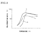
- an active temperature area of selective reduction catalyst may differ depending upon constituent of the catalyst. Therefore, selective reduction catalyst must be properly selected so as to have an active temperature area in conformity with an operation mode of an applied vehicle.
- An active temperature area of selective reduction catalyst is, however, generally smaller than an exhaust temperature range of the vehicle so that, in fact, a high NO x reduction ratio has been obtained only at a part of the exhaust temperature range of the vehicle. Thus, expansion in active temperature area of selective reduction catalyst remains one of large tasks to be settled.
- the invention was made in view of the above and has its object to expand an active temperature area of selective reduction catalyst more than ever before so as to obtain high NO x reduction ratio in a larger exhaust temperature range.
- the invention is directed to an exhaust emission control device with selective reduction catalyst incorporated in an exhaust pipe, said catalyst having enhanced reaction selectivity so as to selectively react NO x with ammonia even in the presence of oxygen, urea water being added as reducing agent upstream of the selective reduction catalyst by urea water adding means so as to reduce and purify NO x , comprising said selective reduction catalyst in the form of two catalysts with different active temperature areas, said catalysts being arranged in series in such a manner that the catalysts with higher and lower active temperature areas are positioned upstream and downstream, respectively.
- ammonia is used as reducing agent both in the upstream and downstream so that performances of both the catalysts exhibit synergistically, resulting in attainment of NO x reduction performance higher than that obtained in the case of a single catalyst.
- the upstream catalyst with higher active temperature area brings about NO x reduction ratio higher than the downstream catalyst with lower active temperature area when the catalyst is in a highly active state.
- An exhaust emission control device of the invention as mentioned above in which two selective reduction catalysts with different active temperature areas are used in combination can bring about excellent effects that active temperature areas of selective reduction catalysts are expanded more than ever before so as to obtain high NO x reduction ratio in a larger exhaust temperature range and that, obtained in an intermediate temperature area where the performances of both the selective reduction catalysts are brought about synergistically, is NO x reduction ratio which is higher than that obtained in a single catalyst, resulting in improvement of the NO x reduction performance.
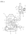
- FIGs. 1 and 2 show the embodiment of the invention in which reference numeral 1 denotes a diesel engine.
- the engine 1 illustrated has a turbocharger 2 with a compressor 2a to which air 4 from an air cleaner 3 is fed via an intake air pipe 5.
- the air 4 thus pressurized in the compressor 2a is further fed to an intercooler 6 where it is cooled.
- the cooled air 4 from the intercooler 6 is guided to an intake manifold (not shown) to be introduced into each of cylinders in the engine 1.
- Exhaust gas 7 discharged from each of the cylinders in the engine 1 is fed via an exhaust manifold 8 to a turbine 2b of the turbocharger 2.
- the exhaust gas 7 thus having driven the turbine 2b is discharged via an exhaust pipe 9 to outside of the vehicle.
- a casing 10 Incorporated in the exhaust pipe 9 through which the exhaust gas 7 flows is a casing 10. Received on an upstream side in the casing 10 is a high-temperature-active selective reduction catalyst 11 with a higher active temperature area and with an enhanced reaction selectivity for selective reaction of NO x with ammonia even in the presence of oxygen; and received on a downstream side in the casing 10 is a low-temperature-active selective reduction catalyst 12 with a lower active temperature area and with a similarly enhanced reaction selectivity.
- the upstream high-temperature-active catalyst 11 may be vanadic catalyst.
- the downstream low-temperature-active catalyst 12 may be Cu-, Fe-, Co- or Ag-zeolitic catalyst or Cu-, Fe-, Co- or Ag-alumina catalyst.
- an inlet zone of the casing 10 in the exhaust pipe is connected through a urea water supply line 14 to a urea water tank 13 arranged in a required site.
- Actuation of a supply pump 15 incorporated in the supply line 14 causes urea water 16 in the tank 13 to be added through an injection nozzle 17 to the inlet zone of the casing 10.
- the urea water tank 13, urea water supply pipe 14, supply pump 15, injection nozzle 17 constitute urea water adding means.
- the exhaust emission control device in a temperature area (lower temperature area) which brings about high activity of the downstream low-temperature-active catalyst 12, the activity of the upstream high-temperature-active catalyst 11 is not so high that the upstream high-temperature-active catalyst 11 has low consumption of ammonia produced by addition of the urea water 16. Most of ammonia passes through the upstream catalyst 11 and reaches the downstream catalyst 12 while it is unreacted. On the low-temperature-active catalyst 12 which is in a highly active state, NO x in the exhaust gas 7 is effectively reduced and purified by ammonia.
- ammonia is used as reducing agent both in the upstream and in the downstream so that performances of both the high- and low-temperature-active catalysts 11 and 12 exhibit synergistically, resulting in attainment of NO x reduction performance higher than that obtained in the case of a single catalyst.
- the upstream high-temperature-active catalyst 11 with higher active temperature area and in a highly active state brings about NO x reduction ratio higher than the downstream low-temperature-active catalyst 12 in a highly active state.
- ammonia would be consumed halfway on the upstream low-temperature-active catalyst 12 with some degree of activity in the higher temperature area, disadvantageously resulting in failure to introduce a sufficient amount of ammonia as reducing agent into the downstream high-temperature-active catalyst 11 by which high NO x reduction ratio is to be inherently obtained.
- high- and low-temperature-active catalysts 11 and 12 with different active temperature areas are used in combination so that active temperature areas of the catalysts are expanded more than ever before so as to obtain high NO x reduction ratio in a larger exhaust temperature range.
- NO x reduction ratio obtained in an intermediate temperature area where the performances of the high- and low-temperature-active catalysts 11 and 12 are brought about synergistically, is NO x reduction ratio which is higher than that obtained in a single catalyst, resulting in improvement of the NO x reduction performance.
Applications Claiming Priority (2)
| Application Number | Priority Date | Filing Date | Title |
|---|---|---|---|
| JP2004242292A JP2006057578A (ja) | 2004-08-23 | 2004-08-23 | 排気浄化装置 |
| PCT/JP2005/015190 WO2006022214A1 (ja) | 2004-08-23 | 2005-08-22 | 排気浄化装置 |
Publications (2)
| Publication Number | Publication Date |
|---|---|
| EP1795724A1 true EP1795724A1 (de) | 2007-06-13 |
| EP1795724A4 EP1795724A4 (de) | 2007-11-21 |
Family
ID=35967426
Family Applications (1)
| Application Number | Title | Priority Date | Filing Date |
|---|---|---|---|
| EP05772485A Withdrawn EP1795724A4 (de) | 2004-08-23 | 2005-08-22 | Abgasreinigungsvorrichtung |
Country Status (4)
| Country | Link |
|---|---|
| US (1) | US20070243120A1 (de) |
| EP (1) | EP1795724A4 (de) |
| JP (1) | JP2006057578A (de) |
| WO (1) | WO2006022214A1 (de) |
Cited By (7)
| Publication number | Priority date | Publication date | Assignee | Title |
|---|---|---|---|---|
| WO2008006427A1 (de) * | 2006-07-08 | 2008-01-17 | Umicore Ag & Co. Kg | Strukturierter scr-katalysator zur reduktion von stickoxiden im abgas von magermotoren unter verwendung von ammoniak als reduktionsmittel |
| EP2090352A1 (de) * | 2008-02-12 | 2009-08-19 | MAN Nutzfahrzeuge AG | Vorrichtung zur Verminderung von Dibenzo-Dioxin- und Dibenzo-Furan-Emissionen aus übergangsmetallhaltigen Katalysatoren |
| WO2009124643A1 (de) * | 2008-04-11 | 2009-10-15 | Umicore Ag & Co. Kg | Abgasreinigungssystem zur behandlung von motorenabgasen mittels scr-katalysator |
| CN102600832A (zh) * | 2012-02-28 | 2012-07-25 | 北京化工大学 | 一种提高脱硝性能的组合催化剂及其应用 |
| US8389432B2 (en) | 2006-09-25 | 2013-03-05 | Umicore Ag & Co. Kg | Structured automotive catalyst with improved thermal ageing stability |
| CN104343506A (zh) * | 2014-10-29 | 2015-02-11 | 凯龙高科技股份有限公司 | 一种用于scr喷射系统的喷头结构 |
| EP2851527A4 (de) * | 2012-05-18 | 2016-03-30 | Isuzu Motors Ltd | Abgasreinigungssystem und abgasreinigungsverfahren |
Families Citing this family (6)
| Publication number | Priority date | Publication date | Assignee | Title |
|---|---|---|---|---|
| JP4704964B2 (ja) * | 2006-06-15 | 2011-06-22 | 本田技研工業株式会社 | NOx浄化システム及びNOx浄化方法 |
| DE102008035562A1 (de) | 2008-07-30 | 2010-02-04 | Emitec Gesellschaft Für Emissionstechnologie Mbh | Abgasreinigungssystem für Dieselmotoren von Nutzkraftfahrzeugen |
| WO2011118777A1 (ja) * | 2010-03-26 | 2011-09-29 | 株式会社 キャタラー | 排ガス浄化システム |
| CA2902414A1 (en) * | 2013-03-14 | 2014-10-02 | Basf Corporation | Selective catalytic reduction catalyst system |
| DE102017204973A1 (de) * | 2017-03-24 | 2018-09-27 | Robert Bosch Gmbh | Verfahren zur Steuerung eines SCR-Systems mit zwei Dosierventilen |
| JP2019035360A (ja) * | 2017-08-14 | 2019-03-07 | いすゞ自動車株式会社 | 排気ガス浄化システム |
Citations (2)
| Publication number | Priority date | Publication date | Assignee | Title |
|---|---|---|---|---|
| WO2000029728A1 (en) * | 1998-11-13 | 2000-05-25 | Engelhard Corporation | STAGED REDUCTANT INJECTION FOR IMPROVED NOx REDUCTION |
| WO2006023932A1 (en) * | 2004-08-23 | 2006-03-02 | Engelhard Corporation | ZONE COATED CATALYST TO SIMULTANEOUSLY REDUCE NOx AND UNREACTED AMMONIA |
Family Cites Families (4)
| Publication number | Priority date | Publication date | Assignee | Title |
|---|---|---|---|---|
| JPH0966223A (ja) * | 1995-09-01 | 1997-03-11 | N E Chemcat Corp | 排気ガス浄化用触媒システム及び排気ガスの浄化方法 |
| JP3483687B2 (ja) * | 1995-11-29 | 2004-01-06 | 日野自動車株式会社 | 排ガス浄化装置 |
| JP3781401B2 (ja) * | 1999-01-26 | 2006-05-31 | 日野自動車株式会社 | 排ガス浄化触媒用還元剤 |
| JP2003290629A (ja) * | 2002-04-02 | 2003-10-14 | Nissan Motor Co Ltd | 排ガス浄化システム |
-
2004
- 2004-08-23 JP JP2004242292A patent/JP2006057578A/ja active Pending
-
2005
- 2005-08-22 WO PCT/JP2005/015190 patent/WO2006022214A1/ja active Application Filing
- 2005-08-22 US US11/574,109 patent/US20070243120A1/en not_active Abandoned
- 2005-08-22 EP EP05772485A patent/EP1795724A4/de not_active Withdrawn
Patent Citations (2)
| Publication number | Priority date | Publication date | Assignee | Title |
|---|---|---|---|---|
| WO2000029728A1 (en) * | 1998-11-13 | 2000-05-25 | Engelhard Corporation | STAGED REDUCTANT INJECTION FOR IMPROVED NOx REDUCTION |
| WO2006023932A1 (en) * | 2004-08-23 | 2006-03-02 | Engelhard Corporation | ZONE COATED CATALYST TO SIMULTANEOUSLY REDUCE NOx AND UNREACTED AMMONIA |
Non-Patent Citations (1)
| Title |
|---|
| See also references of WO2006022214A1 * |
Cited By (13)
| Publication number | Priority date | Publication date | Assignee | Title |
|---|---|---|---|---|
| WO2008006427A1 (de) * | 2006-07-08 | 2008-01-17 | Umicore Ag & Co. Kg | Strukturierter scr-katalysator zur reduktion von stickoxiden im abgas von magermotoren unter verwendung von ammoniak als reduktionsmittel |
| US8568678B2 (en) | 2006-07-08 | 2013-10-29 | Umicore Ag & Co. Kg | Structured SCR catalyst for the reduction of nitrogen oxides in the exhaust gas from lean-burn engines using ammonia as reducing agent |
| US8389432B2 (en) | 2006-09-25 | 2013-03-05 | Umicore Ag & Co. Kg | Structured automotive catalyst with improved thermal ageing stability |
| EP2090352A1 (de) * | 2008-02-12 | 2009-08-19 | MAN Nutzfahrzeuge AG | Vorrichtung zur Verminderung von Dibenzo-Dioxin- und Dibenzo-Furan-Emissionen aus übergangsmetallhaltigen Katalysatoren |
| CN101507900B (zh) * | 2008-02-12 | 2013-12-18 | 曼卡车和巴士股份公司 | 降低来自含过渡金属的催化器的二苯并二噁烯排放和氧芴排放的设备 |
| US8173074B2 (en) | 2008-02-12 | 2012-05-08 | Man Truck & Bus Ag | Apparatus for reducing dibenzodioxin emissions and dibenzofuran emissions from transition metal-containing catalyzers |
| EP2116293A1 (de) | 2008-04-11 | 2009-11-11 | Umicore AG & Co. KG | Abgasreinigungssystem zur Behandlung von Motorenabgasen mittels SCR-Katalysator |
| WO2009124643A1 (de) * | 2008-04-11 | 2009-10-15 | Umicore Ag & Co. Kg | Abgasreinigungssystem zur behandlung von motorenabgasen mittels scr-katalysator |
| US8863507B2 (en) | 2008-04-11 | 2014-10-21 | Umicore Ag & Co. Kg | Exhaust gas purification system for the treatment of engine exhaust gases by means of SCR catalyst |
| CN102600832A (zh) * | 2012-02-28 | 2012-07-25 | 北京化工大学 | 一种提高脱硝性能的组合催化剂及其应用 |
| EP2851527A4 (de) * | 2012-05-18 | 2016-03-30 | Isuzu Motors Ltd | Abgasreinigungssystem und abgasreinigungsverfahren |
| US9394820B2 (en) | 2012-05-18 | 2016-07-19 | Isuzu Motors Limited | Exhaust gas purification system and method for purifying exhaust gas |
| CN104343506A (zh) * | 2014-10-29 | 2015-02-11 | 凯龙高科技股份有限公司 | 一种用于scr喷射系统的喷头结构 |
Also Published As
| Publication number | Publication date |
|---|---|
| EP1795724A4 (de) | 2007-11-21 |
| WO2006022214A1 (ja) | 2006-03-02 |
| JP2006057578A (ja) | 2006-03-02 |
| US20070243120A1 (en) | 2007-10-18 |
Similar Documents
| Publication | Publication Date | Title |
|---|---|---|
| EP1795724A1 (de) | Abgasreinigungsvorrichtung | |
| EP1054722B1 (de) | Vorrichtung zur reduktion von nox in abgasen | |
| US8261538B2 (en) | Compact exhaust gas aftertreatment system | |
| US7490466B2 (en) | Exhaust gas recirculation and selective catalytic reduction system | |
| US8713922B2 (en) | Engine exhaust purification device | |
| JP2006009608A (ja) | 排気浄化装置 | |
| CA2512803A1 (en) | Process for treating ammonia-containing exhaust gases | |
| WO2005124116A1 (ja) | 排気浄化装置 | |
| EP1550796B1 (de) | Verfahren und Vorrichtung zur Kontrolle der Abgastemperatur eines Motors | |
| JP2007182804A (ja) | 排気浄化装置 | |
| US20180010500A1 (en) | Internal Combustion Engine And Method For Operating Same | |
| JP5582854B2 (ja) | 排気ガス浄化装置 | |
| JP2002161732A (ja) | 排気浄化装置 | |
| US8316633B2 (en) | Passive NOx and PM aftertreatment for diesel engine | |
| KR102307828B1 (ko) | 내연 기관 및 그 작동 방법 | |
| JP2005264894A (ja) | 排気浄化装置 | |
| EP2949895B1 (de) | Abgasreiniger | |
| KR101398569B1 (ko) | 배기가스 유로의 구조에 따라 aoc촉매를 이용하여 암모니아 슬립을 정화하는 차량의 엔진용 촉매정화장치 및 제어방법 | |
| CN102656345A (zh) | 发动机的排气净化装置 | |
| US20200003103A1 (en) | Exhaust aftertreatment system for an engine | |
| US20140271385A1 (en) | Catalytic Reduction of NOx | |
| JP2005002925A (ja) | 排気浄化装置 | |
| EP2132421A1 (de) | Abgasreiniger für einen verbrennungsmotor | |
| JP4233418B2 (ja) | 排気浄化装置 | |
| JP2001317346A (ja) | 排気浄化装置 |
Legal Events
| Date | Code | Title | Description |
|---|---|---|---|
| PUAI | Public reference made under article 153(3) epc to a published international application that has entered the european phase |
Free format text: ORIGINAL CODE: 0009012 |
|
| 17P | Request for examination filed |
Effective date: 20070222 |
|
| AK | Designated contracting states |
Kind code of ref document: A1 Designated state(s): DE FR GB |
|
| A4 | Supplementary search report drawn up and despatched |
Effective date: 20071019 |
|
| DAX | Request for extension of the european patent (deleted) | ||
| RBV | Designated contracting states (corrected) |
Designated state(s): DE FR GB |
|
| 17Q | First examination report despatched |
Effective date: 20080222 |
|
| STAA | Information on the status of an ep patent application or granted ep patent |
Free format text: STATUS: THE APPLICATION IS DEEMED TO BE WITHDRAWN |
|
| 18D | Application deemed to be withdrawn |
Effective date: 20080702 |
|
| R18D | Application deemed to be withdrawn (corrected) |
Effective date: 20080704 |