EP1795467A2 - Transfersystem für Behälter zwischen Schiff und Lagerhaus - Google Patents
Transfersystem für Behälter zwischen Schiff und Lagerhaus Download PDFInfo
- Publication number
- EP1795467A2 EP1795467A2 EP06024899A EP06024899A EP1795467A2 EP 1795467 A2 EP1795467 A2 EP 1795467A2 EP 06024899 A EP06024899 A EP 06024899A EP 06024899 A EP06024899 A EP 06024899A EP 1795467 A2 EP1795467 A2 EP 1795467A2
- Authority
- EP
- European Patent Office
- Prior art keywords
- container
- accordance
- containers
- crane
- upper platform
- Prior art date
- Legal status (The legal status is an assumption and is not a legal conclusion. Google has not performed a legal analysis and makes no representation as to the accuracy of the status listed.)
- Granted
Links
Images


Classifications
-
- B—PERFORMING OPERATIONS; TRANSPORTING
- B65—CONVEYING; PACKING; STORING; HANDLING THIN OR FILAMENTARY MATERIAL
- B65G—TRANSPORT OR STORAGE DEVICES, e.g. CONVEYORS FOR LOADING OR TIPPING, SHOP CONVEYOR SYSTEMS OR PNEUMATIC TUBE CONVEYORS
- B65G67/00—Loading or unloading vehicles
- B65G67/60—Loading or unloading ships
- B65G67/603—Loading or unloading ships using devices specially adapted for articles
-
- B—PERFORMING OPERATIONS; TRANSPORTING
- B65—CONVEYING; PACKING; STORING; HANDLING THIN OR FILAMENTARY MATERIAL
- B65G—TRANSPORT OR STORAGE DEVICES, e.g. CONVEYORS FOR LOADING OR TIPPING, SHOP CONVEYOR SYSTEMS OR PNEUMATIC TUBE CONVEYORS
- B65G63/00—Transferring or trans-shipping at storage areas, railway yards or harbours or in opening mining cuts; Marshalling yard installations
- B65G63/002—Transferring or trans-shipping at storage areas, railway yards or harbours or in opening mining cuts; Marshalling yard installations for articles
- B65G63/004—Transferring or trans-shipping at storage areas, railway yards or harbours or in opening mining cuts; Marshalling yard installations for articles for containers
Definitions
- This invention relates to a system of transferring containers between a ship and land.
- Twistlocks are tools which hold together the various superimposed containers on board ships so as to constitute a single block of containers anchored in turn to the bearing structure of the ship to prevent shifting and falling of the load.
- twistlocks belong to the ship and during unloading remain hooked to the lower part of the container from which they must be removed to allow setting down the containers on land or on a land transport means and to be able to again have available the equipment of the ship for loading of new containers.
- cranes have been proposed with two trolleys per winch.
- the first winch takes a container from the ship and sets it down in a waiting position, prearranged in the crane frame, so as to free itself and be able to go and take the next container.
- the second winch takes the container from the waiting position and sets it on the ground after an intermediate stop for removal of the twistlocks.
- the unloading cycle time of a container is however not satisfactory and is heavily conditioned by the time necessary for removal of the twistlocks, a time during which the crane remains stopped to await completion of an operation whose time can vary much depending on various factors such as for example, the skill of the operator, the type and state of preservation of the twistlocks and container, atmospheric conditions in which to operate, et cetera.
- the general purpose of this invention is to remedy the above-mentioned shortcomings by making available a container loading and unloading system allowing high operating speeds with a substantial reduction in the time necessary to transfer a container between a ship and a warehouse while at the same time ensuring that the operators work in fully safe conditions.
- a system on land for transferring containers between ship and land including container loading and unloading cranes and container transfer stations operationally associated with the cranes and characterized in that the transfer stations include an upper platform for receiving and support of a container from and to a crane and a lower platform for container loading and unloading within and outside of the station with there being between the upper and lower platforms centering and lifting means performing transfer of a container between the two superimposed platforms without intervention of the crane.
- FIG 1 shows a system 10 in accordance with this invention for transfer of containers 50 between a ship 11 and a storage warehouse 12.
- the system includes wharf cranes 13 and transfer stations 14.
- the stations can be for example, in the same number as the cranes or there can be more cranes which use the same station alternately.
- the transfer stations are placed between the wharf cranes and the reception station or stations of the containers on land, for example, in the automatic warehouse).
- the transfer stations 14 between crane and warehouse interior include a movable upper platform 15 and a lower platform or shuttle 16.
- the shuttle 16 includes in turn a revolving distributor trolley 17 complete with ensiling car (extractor) 18.
- the upper platform is designed to receive a container from one of the cranes 13 and pass it to an underlying shuttle 16 by means of its own centering and transfer unit 19.
- the platform 15 rests on wheels which run on two rails 20 parallel to the direction of movement of the cranes along the ship and the inlet-outlet face of the warehouse and which are respectively supported on one side on the pavement 21 of the load-unload level and on the other side on the shelving at a height allowing passage of the container beneath the platform 15 for entry into the warehouse 12.
- the shuttle 16 receives the container on the ensiling trolley 18.
- the corresponding trolley 17 can rotate 90° around a vertical axis to take the container from a position (shown in solid lines in FIG 2) which is parallel to the wharf to a position (broken lines in FIG 2) of introduction into the warehouse.
- the rotating platform can rotate 90° either clockwise or counterclockwise allowing thus to present toward the shelves of the warehouse either end of the container depending on necessity (for example, the side of refrigerated containers bearing the connection cable must be oriented toward the side of the ship or the shelving where the appropriate power outlets are available).
- the ensilage trolley 18 extends from the trolley to perform introduction of the container into the warehouse and withdraw again onto the trolley.
- the shuttle 16 can be equipped with a predetermined longitudinal excursion in relation with the predetermined load and unload position so as to be able to unload and load the container directly in one of the predetermined zones of insertion of the containers in the warehouse.
- the shuttle can run on rails 22 parallel to a running direction of the cranes along the ship.
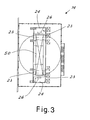
- the unit 19 with which the upper platform is equipped is made up of four telescopic hoists 23 arranged (as may be seen in FIG 3) near the four corners of the receiving zone of a container by the crane.
- the upper platform 15 includes advantageously two positions 24 placed at the short ends of the container reception zone. Each of these positions supports a pair of hoists 23 and is powered to be movable in the direction parallel to the axis along the container and to be able to draw near and away from the other position. This allows adapting the platform to containers of different lengths.
- the movement of the positions 24 can be controlled by a containers size detector or on command of the operators.
- FIG 4 shows one of such positions 24 while the other is basically the same.
- the position includes a movable footboard 25 whose structure carries the two telescopic hoists 23, a longitudinal centerer 26 and an operator protection structure 52 (for example, against material falling from above such as twistlocks or the contents of the container which opened or broke).
- the operator can walk on the footboard to remove the twistlocks from the end of the container.
- the footboard can include containers for the removed twistlocks and also known equipment for reading codes of transferred containers.
- twistlock Insertion and removal of the twistlocks is advantageously performed manually because of the great variety of twistlocks.
- the twistlock insertion and removal operations can also be performed by appropriate robotized means 53 instead of by the operators. This is especially possible in case of standardization of twistlock types used.
- the longitudinal centering device 26 is advantageously made up of an articulated arm 27 bearing guides 28 in suitable plastic or special wear-proof steel shaped so as to couple with the surfaces 29 of the front and rear parts of the containers which are normally provided to guide it. Movement of the arm is controlled by one or two hydraulic cylinders 30.
- the centering device can also be made up of a pair of articulated arms 27 each controlled by its own cylinder.
- the actuators of the centering devices are advantageously provided with a control system of the force exerted which allows damping of the swinging of the container.
- the operator protection structure can be made up of a stout framework supporting the longitudinal centering device and constitutes protection against accidental container movements due to wind, uncertainty in handling of the crane, or any falling of the load from containers which might be accidentally opened during unloading.
- the framework can be covered on the three sides not opposite the container with transparent panels so as to protect the operator from wind, rain or snow. In severe climates, working conditions of the operators can be further improved by inserting radiant panels or other known heating systems in the protective structure.
- each hoist 23 includes a base frame 31 which is supported by support wheels 32 and contrast wheels 33 to be able to move along running beams 34 controlled by a suitable actuator or known type (hydroelectric) not shown.
- the base frame 31 supports a telescopic upright 35 by means of an articulated arm 36.
- the position and tilt of the telescopic upright is determined by the combined action of two hydraulic cylinders 37, 38 the upper one of which performs mainly the function of dampening and the lower that of orientation.
- the tilt actuators are advantageously provided with a control system of the force exerted so as to allow dampening of the swinging of the container lowered between them.
- the telescopic upright 35 is in turn made up of three parts 35a, 35b, 35c mutually running by means of guide wheels and lengthening power (not shown).
- Part 35a is connected to the arm 36 and to the actuator 38 so as to be basically without vertical movement but it has the ability of performing a rotation movement around the upper axis of the arm 36.
- the movable part 35c runs on the movable part 35b which runs on the part 35a.
- On the part 35c runs a slider 39 of reduced length compared with the two movable parts 35 and which ends with a projecting shelf 40.
- the slider 39 bears a special wedge-shaped wear proof plastic or steel guide for guiding a container towards the container support shelf 40.
- the shelf 28 when not loaded with the weight of the container can be oriented in a position (shown in broken lines) which does not interfere with the container and allows passage of the slider beside the container after the container has been set down on the ensilage trolley 18.
- the cranes position a container vertically over a transfer station and set it on the shelves of the telescopic hoists as shown in FIG 2.
- the tilted 'funnel' positioning of the hoists combined with the dampened oscillation of the articulated arms 36 (thanks to the action of the tilt actuators) dampens the swinging of the container suspended from the crane and centers the container in the station.
- the hoists are moved by the pistons to be arranged vertically so that the crane can rest the container finally and free itself and immediately start a new unloading cycle from the ship.
- the orientation of the container for introduction into the warehouse can be obtained by choice with clockwise or counterclockwise rotation, for example to orient the container side equipped with doors or power outlets for a refrigerated system depending on needs.
- the unit 19 After having set down the container, the unit 19 takes the telescopic uprights back on high and arranges itself to receive a new container while taking the hoists back into the tilted configuration of FIG 2.
- the shifting of the platform is obtained by means of electric motors and its position can be determined by the position which the crane assumes for unloading or loading a certain row of containers. Synchronism between the two positions is obtainable advantageously automatically by means of the position data which from the crane control system reach the warehouse control system, which consequently governs the position of the transit stations. The position of the stations can also be 'adjusted' with a manual command by the crane operator if particular operating conditions make it necessary.
- the platform is stopped for all the time used by the crane for unloading and loading a row of containers (bay) from or onto the ship.
- the platform moves at low speed together with the crane only when the crane moves to go to another bay. In this manner the personnel on the platform can work in safe conditions without jolts or unnecessary movements of the platform.
- the rotation movement can take place simultaneously with the translation movement from and to the entry-exit cell of the warehouse container.
- the times to be detracted from the total time cycle are the container centering time and for taking from the waiting position, the time of a brief rise to disconnect the container from the waiting position, the time for lateral shifting to round the waiting position, the time of descent to the twistlock removal position, the time of dampening the oscillations of the container, the time for descent from the twistlock removal position to earth, the time of return to waiting position for taking the next container (rise, lateral shifting, descent).
- Breaking up of the total transfer cycle from the ship to the warehouse using the system in accordance with this invention also has the advantage that it allows good flexibility when starting the operation and gives the personnel time for a visual check of the state and integrity of the container seals, checking whether the code reading cameras have read the codes correctly and for any correction with manual keying in.
Landscapes
- Engineering & Computer Science (AREA)
- Ocean & Marine Engineering (AREA)
- Aviation & Aerospace Engineering (AREA)
- Mechanical Engineering (AREA)
- Ship Loading And Unloading (AREA)
- Warehouses Or Storage Devices (AREA)
Applications Claiming Priority (1)
| Application Number | Priority Date | Filing Date | Title |
|---|---|---|---|
| IT002338A ITMI20052338A1 (it) | 2005-12-06 | 2005-12-06 | Impianto di trasferimento di container fra nave e magazzino |
Publications (3)
| Publication Number | Publication Date |
|---|---|
| EP1795467A2 true EP1795467A2 (de) | 2007-06-13 |
| EP1795467A3 EP1795467A3 (de) | 2008-04-23 |
| EP1795467B1 EP1795467B1 (de) | 2010-09-15 |
Family
ID=37808223
Family Applications (1)
| Application Number | Title | Priority Date | Filing Date |
|---|---|---|---|
| EP06024899A Active EP1795467B1 (de) | 2005-12-06 | 2006-12-01 | Transfersystem für Behälter zwischen Schiff und Lagerhaus |
Country Status (8)
| Country | Link |
|---|---|
| US (1) | US7665945B2 (de) |
| EP (1) | EP1795467B1 (de) |
| CN (1) | CN1978296A (de) |
| AT (1) | ATE481339T1 (de) |
| DE (1) | DE602006016907D1 (de) |
| DK (1) | DK1795467T3 (de) |
| IT (1) | ITMI20052338A1 (de) |
| PT (1) | PT1795467E (de) |
Cited By (17)
| Publication number | Priority date | Publication date | Assignee | Title |
|---|---|---|---|---|
| EP1798169A3 (de) * | 2005-12-14 | 2009-01-14 | Shanghai Zhenhua Port Machinery Co. Ltd. | System mit einem niedrigen Brückengestell und Trägern zum Umsetzen von Containern zwischen einem seeseitigen Kran und einem Kran eines Containerlagers |
| CN103395634A (zh) * | 2013-08-06 | 2013-11-20 | 天津港(集团)有限公司 | 集装箱岸边装卸系统及其装卸方法 |
| ITLI20120007A1 (it) * | 2012-07-30 | 2014-01-31 | Silvio Giannini | Dispositivo di scarico/carico navi progressivo con ponte ed accumulatore. |
| US9914602B2 (en) | 2011-12-21 | 2018-03-13 | Oren Technologies, Llc | Methods of storing and moving proppant at location adjacent rail line |
| US9932183B2 (en) | 2016-01-06 | 2018-04-03 | Oren Technologies, Llc | Conveyor with integrated dust collector system |
| US9969564B2 (en) | 2012-07-23 | 2018-05-15 | Oren Technologies, Llc | Methods and systems to transfer proppant for fracking with reduced risk of production and release of silica dust at a well site |
| US9988215B2 (en) | 2014-09-15 | 2018-06-05 | Oren Technologies, Llc | System and method for delivering proppant to a blender |
| US10059246B1 (en) | 2013-04-01 | 2018-08-28 | Oren Technologies, Llc | Trailer assembly for transport of containers of proppant material |
| USRE47162E1 (en) | 2012-11-02 | 2018-12-18 | Oren Technologies, Llc | Proppant vessel |
| US10239436B2 (en) | 2012-07-23 | 2019-03-26 | Oren Technologies, Llc | Trailer-mounted proppant delivery system |
| US10464741B2 (en) | 2012-07-23 | 2019-11-05 | Oren Technologies, Llc | Proppant discharge system and a container for use in such a proppant discharge system |
| US10518828B2 (en) | 2016-06-03 | 2019-12-31 | Oren Technologies, Llc | Trailer assembly for transport of containers of proppant material |
| US10538381B2 (en) | 2011-09-23 | 2020-01-21 | Sandbox Logistics, Llc | Systems and methods for bulk material storage and/or transport |
| US10662006B2 (en) | 2012-07-23 | 2020-05-26 | Oren Technologies, Llc | Proppant discharge system having a container and the process for providing proppant to a well site |
| US10745194B2 (en) | 2012-07-23 | 2020-08-18 | Oren Technologies, Llc | Cradle for proppant container having tapered box guides and associated methods |
| US10787312B2 (en) | 2012-07-23 | 2020-09-29 | Oren Technologies, Llc | Apparatus for the transport and storage of proppant |
| US11873160B1 (en) | 2014-07-24 | 2024-01-16 | Sandbox Enterprises, Llc | Systems and methods for remotely controlling proppant discharge system |
Families Citing this family (10)
| Publication number | Priority date | Publication date | Assignee | Title |
|---|---|---|---|---|
| DE102006015807A1 (de) * | 2006-03-02 | 2007-09-06 | Rainer Kapelski | Vorrichtung und Verfahren zum Einsetzen und Abnehmen von Twist-Lock-Container-Sicherungsbeschlägen |
| ITMI20061341A1 (it) * | 2006-07-11 | 2008-01-12 | Fata Spa | Carrello di insilaggio shuttle e impianto per la movimentqzione e immagazzinamento di container |
| US20080167817A1 (en) * | 2007-01-06 | 2008-07-10 | Transbotics Corporation | Automated cargo loading systems and methods |
| DE102009053235A1 (de) * | 2009-11-06 | 2011-05-19 | Gottwald Port Technology Gmbh | Umschlagsystem für ISO-Container mit einer Containerbrücke |
| US20120204439A1 (en) * | 2011-02-10 | 2012-08-16 | Michael Kloepfer | Heater for bulk load container vehicle |
| CA2967888C (en) * | 2012-03-22 | 2018-01-30 | Oren Technologies, Llc | Method of storing and moving a proppant |
| WO2014135744A1 (en) * | 2013-03-08 | 2014-09-12 | Cargotec Finland Oy | A method, an apparatus, and a computer program for controlling a container carrier |
| CN104108611B (zh) * | 2013-04-18 | 2016-05-25 | 天津港(集团)有限公司 | 自动化集装箱码头装卸系统及其装卸方法 |
| CN110436348A (zh) * | 2019-09-04 | 2019-11-12 | 润邦卡哥特科工业有限公司 | 一种岸桥集装箱装卸装置 |
| ES2860848A1 (es) * | 2020-04-01 | 2021-10-05 | Mayor Juan Carlos Barbera | Grua portico para contenedores y metodo de funcionamiento |
Citations (5)
| Publication number | Priority date | Publication date | Assignee | Title |
|---|---|---|---|---|
| GB1346520A (en) * | 1971-02-05 | 1974-02-13 | Andersson L | Loading and unloading installations for use with ships |
| US4431359A (en) * | 1979-08-02 | 1984-02-14 | Alberto Toniolo | Elevator for the handling of containers, particularly in harbors |
| US4872798A (en) * | 1987-06-05 | 1989-10-10 | Ide Allan R | Vessel to dock cargo transfer apparatus |
| EP1106564A1 (de) * | 1999-11-30 | 2001-06-13 | Atecs Mannesmann AG | Hubeinrichtung zur Erhöhung der Leistung eines Umschlaggerätes für ISO-Container |
| US20030108406A1 (en) * | 2001-12-11 | 2003-06-12 | Paceco Corp. | Buffer jib crane for cargo container handling operations |
Family Cites Families (10)
| Publication number | Priority date | Publication date | Assignee | Title |
|---|---|---|---|---|
| US1152879A (en) * | 1914-07-31 | 1915-09-07 | Brown Hoisting Machinery Co | Means for hoisting and conveying lumber-packages. |
| JPS5141273B1 (de) * | 1970-12-30 | 1976-11-09 | ||
| JPH072587B2 (ja) * | 1988-06-10 | 1995-01-18 | 三井造船株式会社 | コンテナ荷役方式 |
| US5603598A (en) * | 1994-04-11 | 1997-02-18 | Paceco Corp. | Guide chute for cargo container handling cranes |
| WO1995032146A1 (de) * | 1994-05-20 | 1995-11-30 | Tax Ingenieurgesellschaft Mbh | Lastenverladekran |
| EP0790955B1 (de) * | 1994-09-20 | 1999-07-28 | Fantuzzi-Reggiane S.p.A. | Fracht-behandlungsanlage in einem lager |
| DE19814635C2 (de) * | 1998-03-26 | 2001-04-12 | Mannesmann Ag | Positioniereinrichtung für mindestens eine Palette |
| WO2001046061A1 (en) * | 1999-12-20 | 2001-06-28 | Youngsoo Kwon | Device for loading/unloading cargo and method therefor |
| DE10145513A1 (de) * | 2001-09-14 | 2003-04-10 | Siemens Ag | Verladeeinrichtung für ISO-Container |
| US6845873B1 (en) * | 2003-07-17 | 2005-01-25 | Nigel Chattey | Crane apparatus equipped with container security scanning system |
-
2005
- 2005-12-06 IT IT002338A patent/ITMI20052338A1/it unknown
-
2006
- 2006-12-01 PT PT06024899T patent/PT1795467E/pt unknown
- 2006-12-01 AT AT06024899T patent/ATE481339T1/de not_active IP Right Cessation
- 2006-12-01 EP EP06024899A patent/EP1795467B1/de active Active
- 2006-12-01 DE DE602006016907T patent/DE602006016907D1/de active Active
- 2006-12-01 DK DK06024899.4T patent/DK1795467T3/da active
- 2006-12-06 CN CNA2006101641395A patent/CN1978296A/zh active Pending
- 2006-12-06 US US11/634,279 patent/US7665945B2/en not_active Expired - Fee Related
Patent Citations (5)
| Publication number | Priority date | Publication date | Assignee | Title |
|---|---|---|---|---|
| GB1346520A (en) * | 1971-02-05 | 1974-02-13 | Andersson L | Loading and unloading installations for use with ships |
| US4431359A (en) * | 1979-08-02 | 1984-02-14 | Alberto Toniolo | Elevator for the handling of containers, particularly in harbors |
| US4872798A (en) * | 1987-06-05 | 1989-10-10 | Ide Allan R | Vessel to dock cargo transfer apparatus |
| EP1106564A1 (de) * | 1999-11-30 | 2001-06-13 | Atecs Mannesmann AG | Hubeinrichtung zur Erhöhung der Leistung eines Umschlaggerätes für ISO-Container |
| US20030108406A1 (en) * | 2001-12-11 | 2003-06-12 | Paceco Corp. | Buffer jib crane for cargo container handling operations |
Cited By (32)
| Publication number | Priority date | Publication date | Assignee | Title |
|---|---|---|---|---|
| EP1798169A3 (de) * | 2005-12-14 | 2009-01-14 | Shanghai Zhenhua Port Machinery Co. Ltd. | System mit einem niedrigen Brückengestell und Trägern zum Umsetzen von Containern zwischen einem seeseitigen Kran und einem Kran eines Containerlagers |
| US10562702B2 (en) | 2011-09-23 | 2020-02-18 | Sandbox Logistics, Llc | Systems and methods for bulk material storage and/or transport |
| US10538381B2 (en) | 2011-09-23 | 2020-01-21 | Sandbox Logistics, Llc | Systems and methods for bulk material storage and/or transport |
| US9914602B2 (en) | 2011-12-21 | 2018-03-13 | Oren Technologies, Llc | Methods of storing and moving proppant at location adjacent rail line |
| US10703587B2 (en) | 2011-12-21 | 2020-07-07 | Oren Technologies, Llc | Method of delivering, transporting, and storing proppant for delivery and use at a well site |
| US9969564B2 (en) | 2012-07-23 | 2018-05-15 | Oren Technologies, Llc | Methods and systems to transfer proppant for fracking with reduced risk of production and release of silica dust at a well site |
| US10814767B2 (en) | 2012-07-23 | 2020-10-27 | Oren Technologies, Llc | Trailer-mounted proppant delivery system |
| US10662006B2 (en) | 2012-07-23 | 2020-05-26 | Oren Technologies, Llc | Proppant discharge system having a container and the process for providing proppant to a well site |
| US10569953B2 (en) | 2012-07-23 | 2020-02-25 | Oren Technologies, Llc | Proppant discharge system and a container for use in such a proppant discharge system |
| US10787312B2 (en) | 2012-07-23 | 2020-09-29 | Oren Technologies, Llc | Apparatus for the transport and storage of proppant |
| US10661980B2 (en) | 2012-07-23 | 2020-05-26 | Oren Technologies, Llc | Method of delivering, storing, unloading, and using proppant at a well site |
| US10745194B2 (en) | 2012-07-23 | 2020-08-18 | Oren Technologies, Llc | Cradle for proppant container having tapered box guides and associated methods |
| US10239436B2 (en) | 2012-07-23 | 2019-03-26 | Oren Technologies, Llc | Trailer-mounted proppant delivery system |
| US10661981B2 (en) | 2012-07-23 | 2020-05-26 | Oren Technologies, Llc | Proppant discharge system and a container for use in such a proppant discharge system |
| US10464741B2 (en) | 2012-07-23 | 2019-11-05 | Oren Technologies, Llc | Proppant discharge system and a container for use in such a proppant discharge system |
| ITLI20120007A1 (it) * | 2012-07-30 | 2014-01-31 | Silvio Giannini | Dispositivo di scarico/carico navi progressivo con ponte ed accumulatore. |
| USRE47162E1 (en) | 2012-11-02 | 2018-12-18 | Oren Technologies, Llc | Proppant vessel |
| US10059246B1 (en) | 2013-04-01 | 2018-08-28 | Oren Technologies, Llc | Trailer assembly for transport of containers of proppant material |
| CN103395634B (zh) * | 2013-08-06 | 2016-01-20 | 天津港(集团)有限公司 | 集装箱岸边装卸系统及其装卸方法 |
| CN103395634A (zh) * | 2013-08-06 | 2013-11-20 | 天津港(集团)有限公司 | 集装箱岸边装卸系统及其装卸方法 |
| US11873160B1 (en) | 2014-07-24 | 2024-01-16 | Sandbox Enterprises, Llc | Systems and methods for remotely controlling proppant discharge system |
| US9988215B2 (en) | 2014-09-15 | 2018-06-05 | Oren Technologies, Llc | System and method for delivering proppant to a blender |
| US10399789B2 (en) | 2014-09-15 | 2019-09-03 | Oren Technologies, Llc | System and method for delivering proppant to a blender |
| US10179703B2 (en) | 2014-09-15 | 2019-01-15 | Oren Technologies, Llc | System and method for delivering proppant to a blender |
| US10676296B2 (en) | 2016-01-06 | 2020-06-09 | Oren Technologies, Llc | Conveyor with integrated dust collector system |
| US10065816B2 (en) | 2016-01-06 | 2018-09-04 | Oren Technologies, Llc | Conveyor with integrated dust collector system |
| US10035668B2 (en) | 2016-01-06 | 2018-07-31 | Oren Technologies, Llc | Conveyor with integrated dust collector system |
| US9963308B2 (en) | 2016-01-06 | 2018-05-08 | Oren Technologies, Llc | Conveyor with integrated dust collector system |
| US10926967B2 (en) | 2016-01-06 | 2021-02-23 | Sandbox Enterprises, Llc | Conveyor with integrated dust collector system |
| US11414282B2 (en) | 2016-01-06 | 2022-08-16 | Sandbox Enterprises, Llc | System for conveying proppant to a fracking site hopper |
| US9932183B2 (en) | 2016-01-06 | 2018-04-03 | Oren Technologies, Llc | Conveyor with integrated dust collector system |
| US10518828B2 (en) | 2016-06-03 | 2019-12-31 | Oren Technologies, Llc | Trailer assembly for transport of containers of proppant material |
Also Published As
| Publication number | Publication date |
|---|---|
| EP1795467A3 (de) | 2008-04-23 |
| PT1795467E (pt) | 2010-12-20 |
| DE602006016907D1 (de) | 2010-10-28 |
| CN1978296A (zh) | 2007-06-13 |
| ATE481339T1 (de) | 2010-10-15 |
| ITMI20052338A1 (it) | 2007-06-07 |
| US20070128005A1 (en) | 2007-06-07 |
| DK1795467T3 (da) | 2011-01-10 |
| EP1795467B1 (de) | 2010-09-15 |
| US7665945B2 (en) | 2010-02-23 |
Similar Documents
| Publication | Publication Date | Title |
|---|---|---|
| EP1795467B1 (de) | Transfersystem für Behälter zwischen Schiff und Lagerhaus | |
| US11718477B2 (en) | Vehicle for an automated storage and retrieval system | |
| ES2353154T3 (es) | Sistema de transferancia de contenedores entre barco y almacén. | |
| CA2932890C (en) | Method and apparatus for storing and retrieving or shifting containers in high-bay warehouses | |
| KR100719031B1 (ko) | 아이에스오 컨테이너용 선적 장치 | |
| US6551043B2 (en) | Loading device for ISO containers | |
| EP2346772B1 (de) | Containerhandhabungsystem umfassend ein kran und eine vielzahl der basiselemente die auf der oberseite der container montiert werden zur unterstützung den kran und transport der container | |
| WO2019007318A1 (zh) | 集装箱扭锁自动拆装系统 | |
| EP0167235A1 (de) | Beförderungssystem | |
| US20060182524A1 (en) | Transfer plant and method for loading and unloading containers from container ships | |
| JP2008511481A (ja) | ツイスト・ロックハンドリングシステム | |
| CA2000544A1 (en) | Automated installation for the laying of masonry on a wall | |
| US11802026B2 (en) | Container side loader | |
| EP0133472A2 (de) | Vorrichtung zum senkrechten Stapeln von Behältern | |
| US6435361B2 (en) | Lifting device for increasing the performance of a handling apparatus for ISO containers | |
| EP1927569A1 (de) | Schiff-zu-Land-Containerkran und Verfahren zum Bedienen eines derartigen Krans | |
| CN210736025U (zh) | 一种集装箱端墙自动上总装台装置 | |
| EP3390252B1 (de) | Anlage und verfahren zum automatischen beladen eines behälters | |
| JPH079156B2 (ja) | セグメント搬送装置 | |
| CN215109017U (zh) | 分层进路充填采矿法用放矿装置 | |
| CN107512653A (zh) | 吊具上架及集装箱起重机 | |
| KR20030006012A (ko) | 순환식 스프레더를 구비한 갠트리 크레인 | |
| JP2870338B2 (ja) | 搬送及び格納棚装置 | |
| US20210047114A1 (en) | Storing, retrieving or moving containers in a high-bay warehouse | |
| RU2336418C1 (ru) | Приемная площадка надшахтного здания с обменом вагонеток |
Legal Events
| Date | Code | Title | Description |
|---|---|---|---|
| PUAI | Public reference made under article 153(3) epc to a published international application that has entered the european phase |
Free format text: ORIGINAL CODE: 0009012 |
|
| AK | Designated contracting states |
Kind code of ref document: A2 Designated state(s): AT BE BG CH CY CZ DE DK EE ES FI FR GB GR HU IE IS IT LI LT LU LV MC NL PL PT RO SE SI SK TR |
|
| AX | Request for extension of the european patent |
Extension state: AL BA HR MK YU |
|
| PUAL | Search report despatched |
Free format text: ORIGINAL CODE: 0009013 |
|
| AK | Designated contracting states |
Kind code of ref document: A3 Designated state(s): AT BE BG CH CY CZ DE DK EE ES FI FR GB GR HU IE IS IT LI LT LU LV MC NL PL PT RO SE SI SK TR |
|
| AX | Request for extension of the european patent |
Extension state: AL BA HR MK RS |
|
| RIC1 | Information provided on ipc code assigned before grant |
Ipc: B65G 63/00 20060101AFI20080318BHEP Ipc: B65G 67/60 20060101ALN20080318BHEP |
|
| 17P | Request for examination filed |
Effective date: 20081020 |
|
| 17Q | First examination report despatched |
Effective date: 20081125 |
|
| AKX | Designation fees paid |
Designated state(s): AT BE BG CH CY CZ DE DK EE ES FI FR GB GR HU IE IS IT LI LT LU LV MC NL PL PT RO SE SI SK TR |
|
| AXX | Extension fees paid |
Extension state: HR Payment date: 20081020 Extension state: BA Payment date: 20081020 |
|
| GRAP | Despatch of communication of intention to grant a patent |
Free format text: ORIGINAL CODE: EPIDOSNIGR1 |
|
| GRAS | Grant fee paid |
Free format text: ORIGINAL CODE: EPIDOSNIGR3 |
|
| GRAA | (expected) grant |
Free format text: ORIGINAL CODE: 0009210 |
|
| AK | Designated contracting states |
Kind code of ref document: B1 Designated state(s): AT BE BG CH CY CZ DE DK EE ES FI FR GB GR HU IE IS IT LI LT LU LV MC NL PL PT RO SE SI SK TR |
|
| AX | Request for extension of the european patent |
Extension state: BA HR |
|
| REG | Reference to a national code |
Ref country code: GB Ref legal event code: FG4D Ref country code: CH Ref legal event code: EP |
|
| REG | Reference to a national code |
Ref country code: IE Ref legal event code: FG4D |
|
| REF | Corresponds to: |
Ref document number: 602006016907 Country of ref document: DE Date of ref document: 20101028 Kind code of ref document: P |
|
| REG | Reference to a national code |
Ref country code: PT Ref legal event code: SC4A Free format text: AVAILABILITY OF NATIONAL TRANSLATION Effective date: 20101214 |
|
| REG | Reference to a national code |
Ref country code: NL Ref legal event code: T3 |
|
| REG | Reference to a national code |
Ref country code: DK Ref legal event code: T3 |
|
| PG25 | Lapsed in a contracting state [announced via postgrant information from national office to epo] |
Ref country code: AT Free format text: LAPSE BECAUSE OF FAILURE TO SUBMIT A TRANSLATION OF THE DESCRIPTION OR TO PAY THE FEE WITHIN THE PRESCRIBED TIME-LIMIT Effective date: 20100915 Ref country code: FI Free format text: LAPSE BECAUSE OF FAILURE TO SUBMIT A TRANSLATION OF THE DESCRIPTION OR TO PAY THE FEE WITHIN THE PRESCRIBED TIME-LIMIT Effective date: 20100915 Ref country code: LT Free format text: LAPSE BECAUSE OF FAILURE TO SUBMIT A TRANSLATION OF THE DESCRIPTION OR TO PAY THE FEE WITHIN THE PRESCRIBED TIME-LIMIT Effective date: 20100915 |
|
| PGFP | Annual fee paid to national office [announced via postgrant information from national office to epo] |
Ref country code: DK Payment date: 20101214 Year of fee payment: 5 Ref country code: FR Payment date: 20101222 Year of fee payment: 5 |
|
| LTIE | Lt: invalidation of european patent or patent extension |
Effective date: 20100915 |
|
| REG | Reference to a national code |
Ref country code: ES Ref legal event code: FG2A Effective date: 20110215 |
|
| PG25 | Lapsed in a contracting state [announced via postgrant information from national office to epo] |
Ref country code: PL Free format text: LAPSE BECAUSE OF FAILURE TO SUBMIT A TRANSLATION OF THE DESCRIPTION OR TO PAY THE FEE WITHIN THE PRESCRIBED TIME-LIMIT Effective date: 20100915 Ref country code: CY Free format text: LAPSE BECAUSE OF FAILURE TO SUBMIT A TRANSLATION OF THE DESCRIPTION OR TO PAY THE FEE WITHIN THE PRESCRIBED TIME-LIMIT Effective date: 20100915 Ref country code: SI Free format text: LAPSE BECAUSE OF FAILURE TO SUBMIT A TRANSLATION OF THE DESCRIPTION OR TO PAY THE FEE WITHIN THE PRESCRIBED TIME-LIMIT Effective date: 20100915 |
|
| PGFP | Annual fee paid to national office [announced via postgrant information from national office to epo] |
Ref country code: PT Payment date: 20101217 Year of fee payment: 5 |
|
| PG25 | Lapsed in a contracting state [announced via postgrant information from national office to epo] |
Ref country code: SE Free format text: LAPSE BECAUSE OF FAILURE TO SUBMIT A TRANSLATION OF THE DESCRIPTION OR TO PAY THE FEE WITHIN THE PRESCRIBED TIME-LIMIT Effective date: 20100915 Ref country code: LV Free format text: LAPSE BECAUSE OF FAILURE TO SUBMIT A TRANSLATION OF THE DESCRIPTION OR TO PAY THE FEE WITHIN THE PRESCRIBED TIME-LIMIT Effective date: 20100915 |
|
| PGFP | Annual fee paid to national office [announced via postgrant information from national office to epo] |
Ref country code: GR Payment date: 20101220 Year of fee payment: 5 Ref country code: NL Payment date: 20101216 Year of fee payment: 5 Ref country code: TR Payment date: 20101215 Year of fee payment: 5 |
|
| PG25 | Lapsed in a contracting state [announced via postgrant information from national office to epo] |
Ref country code: RO Free format text: LAPSE BECAUSE OF FAILURE TO SUBMIT A TRANSLATION OF THE DESCRIPTION OR TO PAY THE FEE WITHIN THE PRESCRIBED TIME-LIMIT Effective date: 20100915 Ref country code: IS Free format text: LAPSE BECAUSE OF FAILURE TO SUBMIT A TRANSLATION OF THE DESCRIPTION OR TO PAY THE FEE WITHIN THE PRESCRIBED TIME-LIMIT Effective date: 20110115 Ref country code: CZ Free format text: LAPSE BECAUSE OF FAILURE TO SUBMIT A TRANSLATION OF THE DESCRIPTION OR TO PAY THE FEE WITHIN THE PRESCRIBED TIME-LIMIT Effective date: 20100915 Ref country code: SK Free format text: LAPSE BECAUSE OF FAILURE TO SUBMIT A TRANSLATION OF THE DESCRIPTION OR TO PAY THE FEE WITHIN THE PRESCRIBED TIME-LIMIT Effective date: 20100915 Ref country code: EE Free format text: LAPSE BECAUSE OF FAILURE TO SUBMIT A TRANSLATION OF THE DESCRIPTION OR TO PAY THE FEE WITHIN THE PRESCRIBED TIME-LIMIT Effective date: 20100915 |
|
| PGFP | Annual fee paid to national office [announced via postgrant information from national office to epo] |
Ref country code: DE Payment date: 20101223 Year of fee payment: 5 Ref country code: IT Payment date: 20101213 Year of fee payment: 5 |
|
| PGFP | Annual fee paid to national office [announced via postgrant information from national office to epo] |
Ref country code: ES Payment date: 20101217 Year of fee payment: 5 Ref country code: BE Payment date: 20110114 Year of fee payment: 5 |
|
| PLBE | No opposition filed within time limit |
Free format text: ORIGINAL CODE: 0009261 |
|
| STAA | Information on the status of an ep patent application or granted ep patent |
Free format text: STATUS: NO OPPOSITION FILED WITHIN TIME LIMIT |
|
| PG25 | Lapsed in a contracting state [announced via postgrant information from national office to epo] |
Ref country code: MC Free format text: LAPSE BECAUSE OF NON-PAYMENT OF DUE FEES Effective date: 20101231 |
|
| PGFP | Annual fee paid to national office [announced via postgrant information from national office to epo] |
Ref country code: GB Payment date: 20110114 Year of fee payment: 5 |
|
| REG | Reference to a national code |
Ref country code: CH Ref legal event code: PL |
|
| 26N | No opposition filed |
Effective date: 20110616 |
|
| REG | Reference to a national code |
Ref country code: DE Ref legal event code: R097 Ref document number: 602006016907 Country of ref document: DE Effective date: 20110616 |
|
| PG25 | Lapsed in a contracting state [announced via postgrant information from national office to epo] |
Ref country code: CH Free format text: LAPSE BECAUSE OF NON-PAYMENT OF DUE FEES Effective date: 20101231 Ref country code: IE Free format text: LAPSE BECAUSE OF NON-PAYMENT OF DUE FEES Effective date: 20101201 Ref country code: LI Free format text: LAPSE BECAUSE OF NON-PAYMENT OF DUE FEES Effective date: 20101231 |
|
| BERE | Be: lapsed |
Owner name: FATA S.P.A. Effective date: 20111231 |
|
| REG | Reference to a national code |
Ref country code: NL Ref legal event code: V1 Effective date: 20120701 |
|
| REG | Reference to a national code |
Ref country code: DK Ref legal event code: EBP |
|
| GBPC | Gb: european patent ceased through non-payment of renewal fee |
Effective date: 20111201 |
|
| REG | Reference to a national code |
Ref country code: GR Ref legal event code: ML Ref document number: 20100402958 Country of ref document: GR Effective date: 20120704 |
|
| REG | Reference to a national code |
Ref country code: FR Ref legal event code: ST Effective date: 20120831 |
|
| REG | Reference to a national code |
Ref country code: PT Ref legal event code: MM4A Free format text: LAPSE DUE TO NON-PAYMENT OF FEES Effective date: 20120903 |
|
| PG25 | Lapsed in a contracting state [announced via postgrant information from national office to epo] |
Ref country code: HU Free format text: LAPSE BECAUSE OF FAILURE TO SUBMIT A TRANSLATION OF THE DESCRIPTION OR TO PAY THE FEE WITHIN THE PRESCRIBED TIME-LIMIT Effective date: 20110316 Ref country code: LU Free format text: LAPSE BECAUSE OF NON-PAYMENT OF DUE FEES Effective date: 20101201 Ref country code: BG Free format text: LAPSE BECAUSE OF FAILURE TO SUBMIT A TRANSLATION OF THE DESCRIPTION OR TO PAY THE FEE WITHIN THE PRESCRIBED TIME-LIMIT Effective date: 20100915 |
|
| REG | Reference to a national code |
Ref country code: DE Ref legal event code: R119 Ref document number: 602006016907 Country of ref document: DE Effective date: 20120703 |
|
| PG25 | Lapsed in a contracting state [announced via postgrant information from national office to epo] |
Ref country code: BE Free format text: LAPSE BECAUSE OF NON-PAYMENT OF DUE FEES Effective date: 20111231 Ref country code: DE Free format text: LAPSE BECAUSE OF NON-PAYMENT OF DUE FEES Effective date: 20120703 Ref country code: GB Free format text: LAPSE BECAUSE OF NON-PAYMENT OF DUE FEES Effective date: 20111201 |
|
| PG25 | Lapsed in a contracting state [announced via postgrant information from national office to epo] |
Ref country code: PT Free format text: LAPSE BECAUSE OF NON-PAYMENT OF DUE FEES Effective date: 20120903 Ref country code: GR Free format text: LAPSE BECAUSE OF NON-PAYMENT OF DUE FEES Effective date: 20120704 Ref country code: IT Free format text: LAPSE BECAUSE OF NON-PAYMENT OF DUE FEES Effective date: 20111201 |
|
| PG25 | Lapsed in a contracting state [announced via postgrant information from national office to epo] |
Ref country code: DK Free format text: LAPSE BECAUSE OF NON-PAYMENT OF DUE FEES Effective date: 20120102 Ref country code: NL Free format text: LAPSE BECAUSE OF NON-PAYMENT OF DUE FEES Effective date: 20120701 |
|
| PG25 | Lapsed in a contracting state [announced via postgrant information from national office to epo] |
Ref country code: FR Free format text: LAPSE BECAUSE OF NON-PAYMENT OF DUE FEES Effective date: 20120102 |
|
| PG25 | Lapsed in a contracting state [announced via postgrant information from national office to epo] |
Ref country code: BG Free format text: LAPSE BECAUSE OF FAILURE TO SUBMIT A TRANSLATION OF THE DESCRIPTION OR TO PAY THE FEE WITHIN THE PRESCRIBED TIME-LIMIT Effective date: 20101215 |
|
| REG | Reference to a national code |
Ref country code: ES Ref legal event code: FD2A Effective date: 20131021 |
|
| PG25 | Lapsed in a contracting state [announced via postgrant information from national office to epo] |
Ref country code: ES Free format text: LAPSE BECAUSE OF NON-PAYMENT OF DUE FEES Effective date: 20111202 Ref country code: TR Free format text: LAPSE BECAUSE OF NON-PAYMENT OF DUE FEES Effective date: 20111201 |
|
| REG | Reference to a national code |
Ref country code: GR Ref legal event code: EP Ref document number: 20100402958 Country of ref document: GR Effective date: 20110119 |