EP1792102B1 - Spannvorrichtung mit mechanischer dämpfung für einen zugmitteltrieb - Google Patents
Spannvorrichtung mit mechanischer dämpfung für einen zugmitteltrieb Download PDFInfo
- Publication number
- EP1792102B1 EP1792102B1 EP05774430A EP05774430A EP1792102B1 EP 1792102 B1 EP1792102 B1 EP 1792102B1 EP 05774430 A EP05774430 A EP 05774430A EP 05774430 A EP05774430 A EP 05774430A EP 1792102 B1 EP1792102 B1 EP 1792102B1
- Authority
- EP
- European Patent Office
- Prior art keywords
- friction
- friction lining
- housing
- friction disc
- tensioning apparatus
- Prior art date
- Legal status (The legal status is an assumption and is not a legal conclusion. Google has not performed a legal analysis and makes no representation as to the accuracy of the status listed.)
- Expired - Lifetime
Links
Images




Classifications
-
- F—MECHANICAL ENGINEERING; LIGHTING; HEATING; WEAPONS; BLASTING
- F16—ENGINEERING ELEMENTS AND UNITS; GENERAL MEASURES FOR PRODUCING AND MAINTAINING EFFECTIVE FUNCTIONING OF MACHINES OR INSTALLATIONS; THERMAL INSULATION IN GENERAL
- F16H—GEARING
- F16H7/00—Gearings for conveying rotary motion by endless flexible members
- F16H7/08—Means for varying tension of belts, ropes or chains
- F16H7/10—Means for varying tension of belts, ropes or chains by adjusting the axis of a pulley
- F16H7/12—Means for varying tension of belts, ropes or chains by adjusting the axis of a pulley of an idle pulley
-
- F—MECHANICAL ENGINEERING; LIGHTING; HEATING; WEAPONS; BLASTING
- F16—ENGINEERING ELEMENTS AND UNITS; GENERAL MEASURES FOR PRODUCING AND MAINTAINING EFFECTIVE FUNCTIONING OF MACHINES OR INSTALLATIONS; THERMAL INSULATION IN GENERAL
- F16F—SPRINGS; SHOCK-ABSORBERS; MEANS FOR DAMPING VIBRATION
- F16F15/00—Suppression of vibrations in systems; Means or arrangements for avoiding or reducing out-of-balance forces, e.g. due to motion
- F16F15/10—Suppression of vibrations in rotating systems by making use of members moving with the system
- F16F15/12—Suppression of vibrations in rotating systems by making use of members moving with the system using elastic members or friction-damping members, e.g. between a rotating shaft and a gyratory mass mounted thereon
- F16F15/129—Suppression of vibrations in rotating systems by making use of members moving with the system using elastic members or friction-damping members, e.g. between a rotating shaft and a gyratory mass mounted thereon characterised by friction-damping means
-
- F—MECHANICAL ENGINEERING; LIGHTING; HEATING; WEAPONS; BLASTING
- F16—ENGINEERING ELEMENTS AND UNITS; GENERAL MEASURES FOR PRODUCING AND MAINTAINING EFFECTIVE FUNCTIONING OF MACHINES OR INSTALLATIONS; THERMAL INSULATION IN GENERAL
- F16D—COUPLINGS FOR TRANSMITTING ROTATION; CLUTCHES; BRAKES
- F16D13/00—Friction clutches
-
- F—MECHANICAL ENGINEERING; LIGHTING; HEATING; WEAPONS; BLASTING
- F16—ENGINEERING ELEMENTS AND UNITS; GENERAL MEASURES FOR PRODUCING AND MAINTAINING EFFECTIVE FUNCTIONING OF MACHINES OR INSTALLATIONS; THERMAL INSULATION IN GENERAL
- F16F—SPRINGS; SHOCK-ABSORBERS; MEANS FOR DAMPING VIBRATION
- F16F15/00—Suppression of vibrations in systems; Means or arrangements for avoiding or reducing out-of-balance forces, e.g. due to motion
- F16F15/10—Suppression of vibrations in rotating systems by making use of members moving with the system
- F16F15/12—Suppression of vibrations in rotating systems by making use of members moving with the system using elastic members or friction-damping members, e.g. between a rotating shaft and a gyratory mass mounted thereon
-
- F—MECHANICAL ENGINEERING; LIGHTING; HEATING; WEAPONS; BLASTING
- F16—ENGINEERING ELEMENTS AND UNITS; GENERAL MEASURES FOR PRODUCING AND MAINTAINING EFFECTIVE FUNCTIONING OF MACHINES OR INSTALLATIONS; THERMAL INSULATION IN GENERAL
- F16H—GEARING
- F16H7/00—Gearings for conveying rotary motion by endless flexible members
- F16H7/08—Means for varying tension of belts, ropes or chains
- F16H7/10—Means for varying tension of belts, ropes or chains by adjusting the axis of a pulley
- F16H7/12—Means for varying tension of belts, ropes or chains by adjusting the axis of a pulley of an idle pulley
- F16H7/1209—Means for varying tension of belts, ropes or chains by adjusting the axis of a pulley of an idle pulley with vibration damping means
- F16H7/1218—Means for varying tension of belts, ropes or chains by adjusting the axis of a pulley of an idle pulley with vibration damping means of the dry friction type
-
- F—MECHANICAL ENGINEERING; LIGHTING; HEATING; WEAPONS; BLASTING
- F16—ENGINEERING ELEMENTS AND UNITS; GENERAL MEASURES FOR PRODUCING AND MAINTAINING EFFECTIVE FUNCTIONING OF MACHINES OR INSTALLATIONS; THERMAL INSULATION IN GENERAL
- F16H—GEARING
- F16H7/00—Gearings for conveying rotary motion by endless flexible members
- F16H7/08—Means for varying tension of belts, ropes or chains
- F16H2007/0802—Actuators for final output members
- F16H2007/081—Torsion springs
Definitions
- the invention relates to a tensioning device with mechanical damping for a traction mechanism drive, in particular according to the preamble of patent claim 1, and as known from DE10248352A is known.
- a tension device with mechanical damping which is provided for a traction drive, with a clamping arm which carries a tension roller at one end and is rotatably mounted at its other end via a rotatably connected shaft in a housing and by means of a torsion and compression spring is resiliently supported on the housing, wherein the free end of the shaft is in rotationally fixed connection with a friction disc and a friction lining is disposed between the friction disc and an axial bearing surface of the housing.
- the contact surface of the housing has a plurality of sharp-edged, in the axial direction projecting projections which dig into the friction lining.
- the invention is therefore an object of the invention to provide a tensioner with mechanical damping for traction drives, which is characterized by low Reibbelagverschl inclusion and high damping performance.
- the clamping device comprises a friction disc and a friction lining, the over-corresponding, cooperating and designed as a toothed contact surface are positively connected and thus free of play for transmitting a friction element in both directions of rotation.
- the play-free positive connection between the friction disc and the friction lining a system change of the friction lining between the friction disc and the axial bearing surface of the housing are reliably prevented and an associated noise avoided.
- an overlap between a softer friction lining and a harder friction disc is provided, whereby at the same time sets a backlash-free teeth between these components, which has an advantageous effect on the noise emission.
- the rotationally symmetrical shape of the contact surfaces advantageously causes an equal load in both directions of rotation of the rows.
- the housing made of light metal of the clamping device has a large heat storage capacity, good heat output and a large cooling of the surface, which is beneficial to the self-adjusting temperature of the friction surface of the friction lining effect.
- friction and friction linings are a friction, which has a flat, circular in the basic shape depression for a friction lining, which preferably has four evenly distributed, semi-elliptical indentations with contact surfaces on its circumference, with contact surfaces corresponding bulges of the friction disc in Engage.
- the contact surface of the friction disc and the height contact surface of the matching friction lining have a polygonal shape or a polygonal shape.
- the coverage required for the backlash between the semi-elliptical or the polygonal contact surfaces is realized by deformable Minifixierzähne on the contact surfaces of Sonderreibbeläge.
- Minifixierzähne which are integrally connected to the contact surfaces and arranged radially, are deformed during the pressing of the friction linings in the depressions of the friction plates between the contact surfaces and thus bridge the prevailing between these game. Due to the play-free form-fitting the friction torque can be transmitted without play in both directions of rotation.
- An advantageous further development of the invention consists in that the friction disk and the friction lining have the same spur toothing whose tooth flanks serve as contact surfaces. Due to the spur tooth geometry, the friction lining centers itself on the friction disc and is therefore very easy to assemble. The friction torque is transmitted without play in both directions.
- An advantageous embodiment of the invention is that depending on the circumference of the friction disc and the friction lining each have a spline and the periphery of another friction disc and another friction lining are each arranged a radial toothing, wherein the teeth are designed as toothed couplings and their tooth flanks serve as contact surfaces.
- the transmission of the friction torque on the circumference of the friction disks or the friction linings leads to minimized forces.
- the overlap of the contact surfaces also has an interference fit between the friction plates and the friction linings result, which serves for play-free transmission of the friction torque in both directions of rotation and for axially fixing the friction linings to the friction plates.
- FIGS. 2 to 4 do not fall under the scope of protection.
- FIG. 1 is a longitudinal section through a tensioning device for a traction mechanism shown having a mechanical damping.
- the clamping device consists essentially of a housing 1, a clamping arm 2 and a tensioning roller 3.
- the housing 1 is cup-shaped and integrally connected in its interior with a concentric hub 4.
- a rotatably connected to the clamping arm 2 via a press fit shaft 5 is rotatably mounted in a sliding bearing 6.
- the shaft 5 is also rotatably connected at its free end by a press fit with a friction disc 7, which is in positive connection with a friction lining 8.
- the tensioning arm 2 is acted upon by a torsion spring acting as a helical spring 9 in the direction of a traction means, not shown, for. B. a belt or a chain, biased.
- the coil spring 9 is located inside the cup-shaped Housing 1 and is fixed with one turn end on the clamping arm 2 and the housing 1.
- the coil spring 9 exerts a compressive force on the housing 1 and the clamping arm 2, which is transmitted via the shaft 5 to the friction disc 7 and acts as a contact force of the friction lining 8 on a contact surface 10 of the housing 1.
- the tension roller 3 is formed as a plastic part 11 and fixed on an outer ring 12 of a rolling bearing 13. This is centered on a collar 14 of the clamping arm 2 and connected by a screw 15 with this.
- the rolling bearing 13 is sealed on both sides and covered by a protective flap 16 which engages in the tension roller 3.
- the erfiridungswashen variants of the friction disc 7 and the friction lining 8 are as friction plates 7 'to 7 """or as friction linings 8' to 8""" in the FIGS. 5 to 7 shown, wherein the Figures 2 . 3 and 4 and whose description does not fall within the scope of the invention.
- All friction linings 8 'to 8 “”” are connected to the associated friction disks 7' to 7""" by positive locking and are in frictional contact with the axial contact surface 10 of the housing 1.
- the positive connection via contact surfaces 17 'to 17 “””of the friction plates 7' to 7""” and via contact surfaces 18 'to 18 “” of the friction linings 8' to 8 “””.
- the contact surfaces 17 'to 17 “” and 18' to 18 “”” are arranged in the entire circumferential region of the friction plates 7 'to 7"”” and the friction linings 8' to 8 “”", whereby the forces to be transmitted are minimized.
- contact surfaces 17 to 17 “” and 18 “to 18”” have a rotationally symmetrical shape, they are equally suitable for power transmission in both directions of rotation. Since the mating contact surfaces 17 'to 17 “" and 18' to 18 “""of the friction disks 7 'to 7""" and friction linings 8' to 8 “””have an overlap, a press fit with backlash-free positive locking is ensured between them , with the exception of the solution of FIG. 5 ,
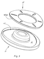
- FIG. 2 the friction disk 7 'is shown. This has a circular in the basic form depression 19 for receiving the friction lining 8 '.
- the friction lining 8 ' has at its periphery four evenly distributed semi-elliptical indentations 20 with the contact surfaces 18 ', which are in engagement with the four contact surfaces 17' of the friction disc 7 '.
- contact surface 17 "of a flat depression 22 of the friction disc 7" and the contact surface 18 "of the matching friction lining 8" have a polygonal shape. This is also suitable for transmitting the friction torque in both directions of rotation of the friction disc 7 ".
- the semi-elliptical contact surfaces 18 'of the friction lining 8' of FIG. 2 and the polygonal contact surfaces 18 "of the friction lining 8" of FIG. 3 have to reach an overlap in one piece with the contact surfaces 18 ', 18 "formed and radially arranged on these Minifixierzähne 23. These deform during the pressing of the friction linings 8', 8" in the depressions 19, 20 of the friction plates 7 ", 7"' and fix there the friction linings 8 ', 8 "backlash.
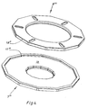
- FIG. 4 shows the friction disc 7 "'with the contact surface 17"' of a flat depression 31 and the matching friction lining 8 "', which has a dodecagon shape the wear height beyond the depressions 19, 22, 31 protrude.
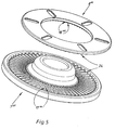
- FIG. 5 are the friction disc 7 "" and the friction lining 8 “” shown having a same spur toothing 24. Their tooth flanks serve as contact surfaces 17 “", 18 "”. Due to the spur gear geometry, the friction lining 8 "" centers itself. Here too, the friction torque is transmitted without play in both directions of rotation.
- FIG. 6 are the friction disc 7 ""'and the friction lining 8 ""' shown, on whose circumference ever an axial toothing 25, 26 is arranged.
- the friction disc 7 """and the friction lining 8""" on whose circumference a respective radial toothing 27, 28 is provided.
- the gears 25, 26 and 27, 28 are designed as toothed couplings whose tooth flanks serve as contact surfaces 17 ''',18''' and 17 ''',18'''.
Landscapes
- Engineering & Computer Science (AREA)
- General Engineering & Computer Science (AREA)
- Mechanical Engineering (AREA)
- Physics & Mathematics (AREA)
- Acoustics & Sound (AREA)
- Aviation & Aerospace Engineering (AREA)
- Mechanical Operated Clutches (AREA)
- Braking Arrangements (AREA)
- Friction Gearing (AREA)
- Devices For Conveying Motion By Means Of Endless Flexible Members (AREA)
- Special Conveying (AREA)
Description
- Die Erfindung betrifft eine Spannvorrichtung mit mechanischer Dämpfung für einen Zugmitteltrieb, insbesondere nach dem Oberbegriff des Patentanspruchs 1, und wie sie aus der
DE10248352A bekannt ist. - In der
DE 43 43 429 C2 ist eine Spannvorrichtung mit mechanischer Dämpfung offenbart, die für einen Zugmitteltrieb vorgesehen ist, mit einem Spannarm, der an einem Ende eine Spannrolle trägt und an seinem anderen Ende über eine drehfest verbundene Welle in einem Gehäuse drehbar gelagert ist und sich mittels einer Torsions- und Druckfeder an dem Gehäuse federnd abstützt, wobei das freie Ende der Welle in drehfester Verbindung mit einer Reibscheibe steht und zwischen der Reibscheibe und einer axialen Anlagefläche des Gehäuses ein Reibbelag angeordnet ist. Die Anlagefläche des Gehäuses weist eine Vielzahl von scharfkantigen, in axialer Richtung vorstehenden Vorsprüngen auf, die sich in den Reibbelag eingraben. Dadurch ist der Reibbelag mit der Anlagefläche des Gehäuses fest verbunden, während die Dämpfungsbewegung zwischen dem Reibbelag und der Reibscheibe stattfindet. Diese Lösung setzt einen relativ weichen Reibbelag voraus, der wenig standfest ist. Außerdem tritt an dem Reibbelag starke Erhitzung auf, da die stählerne Reibscheibe die Reibwärme nur schlecht ableitet. Auch die hohen Temperaturen bedingen einen erhöhten Verschleiß des Reibbelags und verminderte Dämpfungsleistung. - Der Erfindung liegt deshalb die Aufgabe zugrunde, eine Spannvorrichtung mit mechanischer Dämpfung für Zugmitteltriebe zu schaffen, die sich durch niedrigen Reibbelagverschleiß und hohe Dämpfungsleistung auszeichnet.
- Die Aufgabe der Erfindung wird erfindungsgemäß durch die Merkmale des unabhängigen Patentanspruchs 1 gelöst.
- Die erfindungsgemäße Spannvorrichtung umfasst eine Reibscheibe sowie einen Reibbelag, die überkorrespondierende, zusammenwirkende und als Verzahnung ausgebildete Kontaktfläche formschlüssig und damit spielfrei zur Übertragung eines Reibelementes in beide Drehrichtungen verbunden sind. Durch den spielfreien Formschluss zwischen der Reibscheibe und dem Reibbelag werden ein Anlagewechsel des Reibbelags zwischen der Reibscheibe und der axialen Anlagefläche des Gehäuses sicher verhindert und eine damit verbundene Geräuschentwicklung vermieden. Durch eine entsprechende Lage und Größe der Kontaktflächen können die in den Kontaktflächen auftretenden Kräfte und damit deren Verformung und Verschleiß minimiert werden.
- Gemäß einer vorteilhaften weiteren Ausgestaltung der Erfindung ist eine Überdeckung zwischen einem weicheren Reibbelag und einer härteren Reibscheibe vorgesehen, wodurch sich gleichzeitig eine spielfreie Verzahnung zwischen diesen Bauteilen einstellt, die sich vorteilhaft auf die Geräuschemission auswirkt.
- Die drehsymmetrische Form der Kontaktflächen bewirkt vorteilhaft eine gleiche Belastung in beiden Drehrichtungen der Reihen. Das aus Leichtmetall hergestellte Gehäuse der Spannvorrichtung weist eine große Wärmespeicherkapazität, gute Wärmeleistung und eine große kühlen der Oberfläche auf, was sich vorteilhaft auf die sich einstellende Temperatur der Reibfläche des Reibbelags auswirkt.
- Als eine bevorzugte erfindungsgemäße Variante der Reibscheiben und Reibbeläge dient eine Reibscheiben, die eine ebene, in der Grundform kreisförmige Einsenkung für einen Reibbelag besitzt, der an seinem Umfang vorzugsweise vier gleichmäßig verteilte, halbellipsenförmige Einbuchtungen mit Kontaktflächen aufweist, die mit Kontaktflächen entsprechender Ausbuchtungen der Reibscheibe in Eingriff stehen.
- Durch die periphere Lage der Kontaktflächen der halbellipsenförmigen Ein- und ausbuchtungen des Reibbelags bzw. der Reibscheibe ist deren Belastung und damit deren Verformung und Verschleiß minimiert.
- Dasselbe gilt auch, wenn die Kontaktfläche der Reibscheibe und die Höhe Kontaktfläche des dazu passenden Reibbelags eine Polygonform oder eine Vieleckform aufweisen.
- Die für die Spielfreiheit erforderliche Überdeckung zwischen den halbellipsenförmigen bzw. den polygonen Kontaktflächen wird durch verformbare Minifixierzähne auf den Kontaktflächen der Sonderreibbeläge verwirklicht.
- Die Minifixierzähne, die einstückig mit den Kontaktflächen verbunden und radial angeordnet sind, werden beim Einpressen der Reibbeläge in die Einsenkungen der Reibscheiben zwischen den Kontaktflächen verformt und überbrücken so das zwischen diesen herrschende Spiel. Durch den spielfreien Formschluss kann das Reibmoment spielfrei in beide Drehrichtungen übertragen werden.
- Eine vorteilhafte Weiterentwicklung der Erfindung besteht darin, dass die Reibscheibe und der Reibbelag eine gleiche Stirnverzahnung aufweisen, deren Zahnflanken als Kontaktflächen dienen. Aufgrund der Stirnzahngeometrie zentriert sich der Reibbelag von selbst auf der Reibscheibe und ist dadurch sehr montagefreundlich. Das Reibmoment wird auch hier spielfrei in beide Drehrichtungen übertragen.
- Eine vorteilhafte Ausbildung der Erfindung besteht darin, dass am Umfang der Reibscheibe und des Reibbelags je eine Axialverzahnung und am Umfang einer anderen Reibscheibe und eines anderen Reibbelags je eine Radialverzahnung angeordnet sind, wobei die Verzahnungen als Zahnkupplungen ausgebildet sind und deren Zahnflanken als Kontaktflächen dienen.
- Auch bei diesen Varianten gilt, dass die Übertragung des Reibmoments am Umfang der Reibscheiben bzw. der Reibbeläge zu minimierten Kräften führt. Die Überdeckung der Kontaktflächen hat auch hier einen Presssitz zwischen den Reibscheiben und den Reibbelägen zur Folge, der zur spielfreien Übertragung des Reibmoments in beide Drehrichtungen und zur axialen Fixierung der Reibbeläge an den Reibscheiben dient.
- Der mit Ausnahme der stirnverzahnten Variante mögliche Einbau eines Dämpfungselements zwischen Reibscheibe und Reibbelag vermindert die Geräuschübertragung in diesem Bereich.
- Weitere Merkmale der Erfindung ergeben sich aus der folgenden Beschreibung und den Zeichnungen, in denen Ausführungsbeispiele der Erfindung schematisch dargestellt sind.
- Es zeigen:
- Figur 1
- einen Längsschnitt durch eine mechanisch gedämpfte Spannvorrichtung;
- Figur 2
- perspektivische Ansicht einer Reibscheibe und eines dazu passenden Reibbelags mit halbelliptischen Kontaktflächen;
- Figur 3
- perspektivische Ansicht einer Reibscheibe und eines dazu passenden Reibbelags mit einer polygonalen Kontaktflä- che;
- Figur 4
- perspektivische Ansicht einer Reibscheibe und eines dazu passenden Reibbelags mit einer zwölfeckigen Kontaktflä- che;
- Figur 5
- perspektivische Ansicht einer Reibscheibe und des dazu passenden Reibbelags mit Stirnverzahnung;
- Figur 6
- perspektivische Ansicht einer Reibscheibe und des dazu passenden Reibbelags mit axialer Verzahnung am Umfang;
- Figur 7
- perspektivische Ansicht einer Reibscheibe und des dazu passenden Reibbelags mit radialer Verzahnung am Um- fang.
- Die
Figuren 2 bis 4 fallen nicht unter dem Schutzumfang. - In
Figur 1 ist ein Längsschnitt durch eine Spannvorrichtung für einen Zugmitteltrieb dargestellt, die eine mechanische Dämpfung aufweist. - Die Spannvorrichtung besteht im Wesentlichen aus einem Gehäuse 1, einem Spannarm 2 und einer Spannrolle 3. Das Gehäuse 1 ist tassenartig ausgebildet und in seinem Inneren mit einer konzentrischen Nabe 4 einstückig verbunden. In der Nabe 4 ist eine mit dem Spannarm 2 über einen Presssitz drehfest verbundene Welle 5 in einem Gleitlager 6 drehbar gelagert. Die Welle 5 ist an ihrem freien Ende ebenfalls durch Presssitz mit einer Reibscheibe 7 drehfest verbunden, die in formschlüssiger Verbindung mit einem Reibbelag 8 steht. Der Spannarm 2 wird über eine als Torsionsfeder wirkende Schraubenfeder 9 in Richtung eines nicht dargestellten Zugmittels, z. B. eines Riemens oder einer Kette, vorgespannt. Die Schraubenfeder 9 befindet sich im Inneren des tassenförmigen Gehäuses 1 und ist mit je einem Windungsende am Spannarm 2 und am Gehäuse 1 fixiert. Die Schraubenfeder 9 übt eine Druckkraft auf das Gehäuse 1 und den Spannarm 2 aus, die über die Welle 5 auf die Reibscheibe 7 übertragen wird und als Anpresskraft des Reibbelags 8 auf eine Anlagefläche 10 des Gehäuses 1 wirkt.
- Die Spannrolle 3 ist als Kunststoffteil 11 ausgebildet und auf einem Außenring 12 eines Wälzlagers 13 befestigt. Dieses ist auf einem Bund 14 des Spannarms 2 zentriert und durch eine Schraube 15 mit diesem verbunden. Das Wälzlager 13 ist beidseitig abgedichtet und durch eine Schutzklappe 16 abgedeckt, die in die Spannrolle 3 einrastet.
- Die erfiridungsgemäßen Varianten der Reibscheibe 7 bzw. des Reibbelags 8 sind als Reibscheiben 7' bis 7""" bzw. als Reibbeläge 8' bis 8""" in den
Figuren 5 bis 7 dargestellt, wobei dieFiguren 2 ,3 und4 und deren Beschreibung nicht unter den Schutzumfang der Erfindung fallen. - Alle Reibbeläge 8' bis 8""" sind mit den zugehörigen Reibscheiben 7' bis 7""" durch Formschluss verbunden und stehen mit der axialen Anlagefläche 10 des Gehäuses 1 in Reibkontakt. Der Formschluss erfolgt über Kontaktflächen 17' bis 17""" der Reibscheiben 7' bis 7""" und über Kontaktflächen 18' bis 18""" der Reibbeläge 8' bis 8""". Die Kontaktflächen 17' bis 17""" und 18' bis 18""" sind im gesamten Umfangsbereich der Reibscheiben 7' bis 7""" und der Reibbeläge 8' bis 8""" angeordnet, wodurch die zu übertragenden Kräfte minimiert werden. Da die Kontaktflächen17 bis 17""" und 18' bis 18""" eine drehsymmetrische Form aufweisen, sind sie für eine Kraftübertragung in beide Drehrichtungen gleichermaßen geeignet. Da die zusammenpassenden Kontaktflächen 17' bis 17""" und 18' bis 18""" der Reibscheiben 7' bis 7""" und Reibbeläge 8' bis 8""" eine Überdeckung aufweisen, ist zwischen diesen ein Presssitz mit spielfreiem Formschluss gewährleistet, mit Ausnahme der Lösung von
Figur 5 . - In
Figur 2 ist die Reibscheibe 7' dargestellt. Diese besitzt eine in der Grundform kreisförmige Einsenkung 19 zur Aufnahme des Reibbelags 8'. Der Reibbelag 8' weist an seinem Umfang vier gleichmäßig verteilte halbellipsenförmige Einbuchtungen 20 mit den Kontaktflächen 18' auf, die mit den vier Kontaktflächen 17' der Reibscheibe 7' in Eingriff stehen. - Die in
Figur 3 dargestellte Kontaktfläche 17" einer ebenen Einsenkung 22 der Reibscheibe 7" und die Kontaktfläche 18" des dazu passenden Reibbelags 8" weisen eine Polygonform auf. Auch diese eignet sich zur Übertragung des Reibmoments in beide Drehrichtungen der Reibscheibe 7". - Die halbellipsenförmigen Kontaktflächen 18' des Reibbelags 8' der
Figur 2 und die polygonen Kontaktflächen 18" des Reibbelags 8" derFigur 3 weisen zum Erreichen einer Überdeckung einstückig mit den Kontaktflächen 18', 18" ausgebildete und radial auf diesen angeordnete Minifixierzähne 23 auf. Diese verformen sich beim Einpressen der Reibbeläge 8', 8" in die Einsenkungen 19, 20 der Reibscheiben 7", 7"' und fixieren dort die Reibbeläge 8', 8" spielfrei. - Die
Figur 4 zeigt die Reibscheibe 7"' mit der Kontaktfläche 17"' einer ebenen Einsenkung 31 und den dazu passenden Reibbelag 8"', der eine Zwölfeckform aufweist. Die Dicke der Reibbeläge 8', 8", 8'" ist so gewählt, dass diese um die Verschleißhöhe über die Einsenkungen 19, 22, 31 hinausragen. - In
Figur 5 sind die Reibscheibe 7"" und der Reibbelag 8"" dargestellt, die eine gleiche Stirnverzahnung 24 aufweisen. Deren Zahnflanken dienen als Kontaktflächen 17"", 18"". Aufgrund der Stirnzahngeometrie zentriert sich der Reibbelag 8"" von selbst. Auch hier wird das Reibmoment spielfrei in beide Drehrichtungen übertragen. - In
Figur 6 sind die Reibscheibe 7""' und der Reibbelag 8""' dargestellt, an deren Umfang je eine Axialverzahnung 25, 26 angeordnet ist. - Entsprechend zeigt
Figur 7 die Reibscheibe 7""" und den Reibbelag 8""", an deren Umfang je eine Radialverzahnung 27, 28 vorgesehen ist. Die Verzahnungen 25, 26 und 27, 28 sind als Zahnkupplungen ausgebildet, deren Zahnflanken als Kontaktflächen 17""', 18""' und 17""", 18""" dienen. - Über die angeführten Beispiele hinaus fallen alle denkbaren drehsymmetrischen Kontaktflächen von Reibscheiben und dazu passende Reibbeläge unter das Schutzbegehren.
-
- 1
- Gehäuse
- 2
- Spannarm
- 3
- Spannrolle
- 4
- Nabe
- 5
- Welle
- 6
- Gleitlager
- 7
- Reibscheibe
- 7' bis 7"""
- Reibscheibe
- 8
- Reibbelag
- 8' bis 8"""
- Reibbelag
- 9
- Schraubenfeder
- 10
- Anlagefläche
- 11
- Kunststoffteil
- 12
- Außenring
- 13
- Wälzlager
- 14
- Bund
- 15
- Schraube
- 16
- Schutzkappe
- 17' bis 17"""
- Kontaktfläche der Reibscheibe
- 18' bis 18"""
- Kontaktfläche des Reibbelags
- 19
- Einsenkung
- 20
- Einbuchtung
- 21
- Ausbuchtung
- 22
- Einsenkung
- 23
- Minifixierzahn
- 24
- Stirnverzahnung
- 25
- radiale Außenverzahnung
- 26
- axiale Verzahnung
- 27
- radiale Innenverzahnung
- 28
- radiale Außenverzahnung
- 29
- Einsenkung
Claims (8)
- Spannvorrichtung mit mechanischer Dämpfung für einen Zugmitteltrieb, mit einem Spannarm, der an einem Ende eine Spannrolle trägt und an seinem anderen Ende über eine drehfest verbundene Welle in einem Gehäuse drehbar gelagert ist und sich mittels einer Torsions- und Druckfeder an dem Gehäuse federnd abstützt, wobei das freie Ende der Welle in drehfester Verbindung mit einer Reibscheibe steht und zwischen der Reibscheibe und einer axialen Anlagefläche des Gehäuses ein Reibbelag angeordnet ist, dadurch gekennzeichnet, dass die Reibscheibe (7' bis 7""") mit dem Reibbelag (8' bis 8"' "') über korrespondierende, zusammenpassende, als Verzahnung ausgebildete Kontaktflächen (17' bis 17""" und 18' bis 18""") formschlüssig und spielfrei zur Übertragung eines Reibmomentes in beide Drehrichtungen verbunden sind.
- Spannvorrichtung nach Anspruch 1, dadurch gekennzeichnet, dass die zusammenpassenden Kontaktflächen (17' bis 17""" und 18' bis 18""") der Reibscheiben (7' bis 7""") und Reibbeläge (8' bis 8""") eine Überdeckung aufweisen, die durch Zusammenpressen zu dem spielfreien Formschluss führt.
- Spannvorrichtung nach Anspruch 1, dadurch gekennzeichnet, dass die Kontaktflächen (17' bis 17""" und 18' bis 18""") drehsymmetrisch ausgebildet sind.
- Spannvorrichtung nach Anspruch 2, dadurch gekennzeichnet, dass die Reibscheiben (7') eine ebene, in der Grundform kreisförmige Einsenkung (19) für den Reibbelag (8') besitzt, der an seinem Umfang vorzugsweise vier gleichmäßig verteilte, halbellipsenförmige Einbuchtungen (20) mit Kontaktflächen (18') aufweist, die mit Kontaktflächen (17') entsprechender Ausbuchtungen (21) der Reibscheibe (7') in Eingriff stehen.
- Spannvorrichtung nach einem der Ansprüche 1 bis 4 , dadurch gekennzeichnet, dass die Kontaktfläche (17"), die eine ebene Einsenkung (22) der Reibscheibe (7") begrenzt und die Kontaktfläche (18") des dazu passenden Reibbelags (8") eine Polygonform aufweisen.
- Spannvorrichtung nach einem der Ansprüche 1 bis 5, dadurch gekennzeichnet, dass verformbare Minifixierzähne (23) vorgesehen sind, die einstückig mit den Kontaktflächen (18', 18") verbunden und radial angeordnet sind.
- Spannvorrichtung nach einem der vorhergehenden Ansprüche 1 bis 7, dadurch gekennzeichnet, dass die Reibscheibe (7"") und der Reibbelag (8"") eine gleiche Stirnverzahnung (24) aufweisen, deren Zahnflanken als Kontaktflächen (17"", 18"") dienen.
- Spannvorrichtung nach einem der Ansprüche 1 bis 8 , dadurch gekennzeichnet, dass am Umfang der Reibscheibe (7""') und des Reibbelags (8""') je eine Axialverzahnung (25, 26) und am Umfang der der Reibscheibe (7""") und des Reibbelags (8""") je eine Radialverzahnung (27, 28) angeordnet sind, wobei die Verzahnungen (25, 26 und 27, 28) als Zahnkupplungen ausgebildet sind und deren Zahnflanken als Kontaktflächen (17""', 18""' und 17""", 18""") dienen.
Applications Claiming Priority (2)
| Application Number | Priority Date | Filing Date | Title |
|---|---|---|---|
| DE102004046092A DE102004046092A1 (de) | 2004-09-23 | 2004-09-23 | Spannvorrichtung mit mechanischer Dämpfung für einen Zugmitteltrieb |
| PCT/EP2005/008712 WO2006032328A1 (de) | 2004-09-23 | 2005-08-11 | Spannvorrichtung mit mechanischer dämpfung für einen zugmitteltrieb |
Publications (2)
| Publication Number | Publication Date |
|---|---|
| EP1792102A1 EP1792102A1 (de) | 2007-06-06 |
| EP1792102B1 true EP1792102B1 (de) | 2009-03-18 |
Family
ID=35159893
Family Applications (1)
| Application Number | Title | Priority Date | Filing Date |
|---|---|---|---|
| EP05774430A Expired - Lifetime EP1792102B1 (de) | 2004-09-23 | 2005-08-11 | Spannvorrichtung mit mechanischer dämpfung für einen zugmitteltrieb |
Country Status (7)
| Country | Link |
|---|---|
| US (1) | US7993226B2 (de) |
| EP (1) | EP1792102B1 (de) |
| KR (1) | KR101237711B1 (de) |
| CN (1) | CN100473873C (de) |
| AT (1) | ATE426113T1 (de) |
| DE (2) | DE102004046092A1 (de) |
| WO (1) | WO2006032328A1 (de) |
Families Citing this family (7)
| Publication number | Priority date | Publication date | Assignee | Title |
|---|---|---|---|---|
| DE102006047095B4 (de) * | 2006-10-05 | 2021-05-12 | Schaeffler Technologies AG & Co. KG | Spannvorrichtung |
| DE102008021037A1 (de) * | 2008-04-26 | 2009-10-29 | Schaeffler Kg | Hebellagerung mit eingespritztem Gleitlager |
| DE102010019054A1 (de) * | 2010-05-03 | 2011-11-03 | Schaeffler Technologies Gmbh & Co. Kg | Spannvorrichtung |
| CN101943223B (zh) * | 2010-08-31 | 2013-04-03 | 崔洪亮 | 利用被卷物料拉力自动控制的机械式差速离合器 |
| DE202010017870U1 (de) * | 2010-09-03 | 2012-11-27 | Schaeffler Technologies AG & Co. KG | Exzenter-Spannrolle |
| CN106112077B (zh) * | 2016-08-23 | 2018-09-14 | 嘉兴蓝森机械有限公司 | 汽车空调压缩机的驱动轴加工装置 |
| US12662097B2 (en) * | 2023-04-25 | 2026-06-23 | ZF Active Safety US Inc. | Brake system apparatuses, methods, and arrangements |
Family Cites Families (15)
| Publication number | Priority date | Publication date | Assignee | Title |
|---|---|---|---|---|
| DE2055678B1 (de) * | 1970-11-12 | 1972-03-09 | Heinemann R | Bremse oder Kupplung |
| US4689037A (en) * | 1986-06-09 | 1987-08-25 | Litens Automotive, Inc. | Belt tensioning device with constant or variably proportional damping |
| US4902267A (en) * | 1989-06-12 | 1990-02-20 | Dayco Products, Inc. | Belt tensioner, kit therefor and methods of making the same |
| DE9006488U1 (de) * | 1990-06-08 | 1990-08-16 | SKF GmbH, 8720 Schweinfurt | Reibscheibe für gedämpfte Schwenklager |
| US5236196A (en) * | 1991-12-02 | 1993-08-17 | Karl Blankenburg | Spherical body formed of polygonal members |
| DE4343429C2 (de) * | 1993-12-18 | 1999-08-12 | Schaeffler Waelzlager Ohg | Spannvorrichtung für einen Riemen- oder Kettentrieb |
| JP3795226B2 (ja) * | 1998-05-15 | 2006-07-12 | 株式会社ジェイテクト | オートテンショナ |
| DE29914381U1 (de) * | 1999-08-17 | 2000-03-02 | INA Wälzlager Schaeffler oHG, 91074 Herzogenaurach | Spannvorrichtung für einen Zugmitteltrieb |
| DE19946057A1 (de) * | 1999-09-25 | 2001-03-29 | Schaeffler Waelzlager Ohg | Dämpfung von Reibpartnern einer mechanischen Spannvorrichtung |
| JP2001153196A (ja) * | 1999-11-29 | 2001-06-08 | Koyo Seiko Co Ltd | オートテンショナ |
| US7588507B2 (en) * | 2001-04-13 | 2009-09-15 | Unitta Company | Thin autotensioner |
| CN2566054Y (zh) * | 2002-08-09 | 2003-08-13 | 中国重型汽车集团有限公司 | 一种中间皮带轮调整张紧机构 |
| DE10248352A1 (de) * | 2002-10-17 | 2004-04-29 | Ina-Schaeffler Kg | Spannvorrichtung für einen Zugmitteltrieb |
| DE102006047095B4 (de) * | 2006-10-05 | 2021-05-12 | Schaeffler Technologies AG & Co. KG | Spannvorrichtung |
| DE102007051747A1 (de) * | 2006-11-27 | 2008-05-29 | Schaeffler Kg | Spannvorrichtung für einen Zugmitteltrieb mit einer verbesserten Axiallageranordnung |
-
2004
- 2004-09-23 DE DE102004046092A patent/DE102004046092A1/de not_active Withdrawn
-
2005
- 2005-08-11 AT AT05774430T patent/ATE426113T1/de not_active IP Right Cessation
- 2005-08-11 KR KR1020077008958A patent/KR101237711B1/ko not_active Expired - Fee Related
- 2005-08-11 CN CNB2005800321213A patent/CN100473873C/zh not_active Expired - Fee Related
- 2005-08-11 WO PCT/EP2005/008712 patent/WO2006032328A1/de not_active Ceased
- 2005-08-11 EP EP05774430A patent/EP1792102B1/de not_active Expired - Lifetime
- 2005-08-11 DE DE502005006891T patent/DE502005006891D1/de not_active Expired - Lifetime
- 2005-08-11 US US11/575,880 patent/US7993226B2/en not_active Expired - Fee Related
Also Published As
| Publication number | Publication date |
|---|---|
| DE102004046092A1 (de) | 2006-03-30 |
| CN101027505A (zh) | 2007-08-29 |
| KR101237711B1 (ko) | 2013-02-28 |
| ATE426113T1 (de) | 2009-04-15 |
| EP1792102A1 (de) | 2007-06-06 |
| US20090321211A1 (en) | 2009-12-31 |
| KR20070053357A (ko) | 2007-05-23 |
| CN100473873C (zh) | 2009-04-01 |
| WO2006032328A1 (de) | 2006-03-30 |
| DE502005006891D1 (de) | 2009-04-30 |
| US7993226B2 (en) | 2011-08-09 |
Similar Documents
| Publication | Publication Date | Title |
|---|---|---|
| EP1908972B1 (de) | Entkopplungsvorrichtung für eine Lagerung einer Welle an einem Grundkörper sowie Radialwellfeder | |
| DE10119334C1 (de) | Reibungskupplung | |
| EP2145118B1 (de) | Drehmomenten-/drehzahldifferenzabhängige kupplungsbetätigungseinheit für motorangetriebene fahrzeuge | |
| EP1988306B1 (de) | Kupplungsscheibe | |
| EP1612386B1 (de) | Triebrad zum Antreiben eines Nebenaggregates eines Fahrzeuges | |
| DE19634973C2 (de) | Kupplungs- oder Bremsanordnung | |
| DE102007058018A1 (de) | Triebrad | |
| DE2751044A1 (de) | Vorrichtung zur daempfung von drehschwingungen, insbesondere fuer kraftfahrzeugkupplungen | |
| DE4418390C2 (de) | Schwungrad mit einer reibungserzeugenden Anordnung | |
| DE112010001889T5 (de) | Getriebeanordnung für ein elektrisches Servolenkungssystem | |
| DE102017119460B3 (de) | Wellgetriebe | |
| DE102011003030B4 (de) | Kupplungsscheibe für eine Reibungskupplung eines Kraftfahrzeugs | |
| DE102004046092A1 (de) | Spannvorrichtung mit mechanischer Dämpfung für einen Zugmitteltrieb | |
| EP1496288B1 (de) | Torsionsschwingungsdämpfer | |
| EP2302255B1 (de) | Antriebsvorrichtung für zumindest einen Nebentrieb | |
| DE10261516B4 (de) | Axialverstellvorrichtung mit Abfederung im Rücklauf | |
| EP1589244A1 (de) | Mitnehmereinheit mit axial vorgespannter Mitnehmerscheibe | |
| DE102011008703B4 (de) | Vorrichtung zur trieblichen Verbindung | |
| DE102004058177B4 (de) | Zahnrad | |
| EP1460303A1 (de) | Torsionsschwingungsdämpfer | |
| WO2020253906A1 (de) | Wellgetriebe und verfahren zur montage eines wellgetriebes | |
| DE3334657A1 (de) | Reibungskupplung mit kupplungsscheibe und spielunterdrueckung zwischen nabe und getriebewelle | |
| DE10312472B4 (de) | Schwingungsdämpfungssystem | |
| DE102021107296B3 (de) | Verspanneinrichtung, Hybridmodul mit Verspanneinrichtung und Verfahren zur Montage einer Verspanneinrichtung | |
| DE3402918C1 (de) | Differentialgetriebe mit einer vom Zahndruck unabhängigen vorgespannten Sperrkupplung |
Legal Events
| Date | Code | Title | Description |
|---|---|---|---|
| PUAI | Public reference made under article 153(3) epc to a published international application that has entered the european phase |
Free format text: ORIGINAL CODE: 0009012 |
|
| 17P | Request for examination filed |
Effective date: 20070316 |
|
| AK | Designated contracting states |
Kind code of ref document: A1 Designated state(s): AT BE BG CH CY CZ DE DK EE ES FI FR GB GR HU IE IS IT LI LT LU LV MC NL PL PT RO SE SI SK TR |
|
| RIN1 | Information on inventor provided before grant (corrected) |
Inventor name: KAISER, JOERG Inventor name: MENNERAT, THOMAS Inventor name: WILHELM, MANFRED Inventor name: HARTMANN, BERND Inventor name: MACK, STEFAN |
|
| 17Q | First examination report despatched |
Effective date: 20070806 |
|
| DAX | Request for extension of the european patent (deleted) | ||
| GRAP | Despatch of communication of intention to grant a patent |
Free format text: ORIGINAL CODE: EPIDOSNIGR1 |
|
| GRAS | Grant fee paid |
Free format text: ORIGINAL CODE: EPIDOSNIGR3 |
|
| GRAA | (expected) grant |
Free format text: ORIGINAL CODE: 0009210 |
|
| AK | Designated contracting states |
Kind code of ref document: B1 Designated state(s): AT BE BG CH CY CZ DE DK EE ES FI FR GB GR HU IE IS IT LI LT LU LV MC NL PL PT RO SE SI SK TR |
|
| REG | Reference to a national code |
Ref country code: GB Ref legal event code: FG4D Free format text: NOT ENGLISH |
|
| REG | Reference to a national code |
Ref country code: CH Ref legal event code: EP |
|
| REG | Reference to a national code |
Ref country code: IE Ref legal event code: FG4D Free format text: LANGUAGE OF EP DOCUMENT: GERMAN |
|
| REF | Corresponds to: |
Ref document number: 502005006891 Country of ref document: DE Date of ref document: 20090430 Kind code of ref document: P |
|
| PG25 | Lapsed in a contracting state [announced via postgrant information from national office to epo] |
Ref country code: FI Free format text: LAPSE BECAUSE OF FAILURE TO SUBMIT A TRANSLATION OF THE DESCRIPTION OR TO PAY THE FEE WITHIN THE PRESCRIBED TIME-LIMIT Effective date: 20090318 Ref country code: SI Free format text: LAPSE BECAUSE OF FAILURE TO SUBMIT A TRANSLATION OF THE DESCRIPTION OR TO PAY THE FEE WITHIN THE PRESCRIBED TIME-LIMIT Effective date: 20090318 Ref country code: LT Free format text: LAPSE BECAUSE OF FAILURE TO SUBMIT A TRANSLATION OF THE DESCRIPTION OR TO PAY THE FEE WITHIN THE PRESCRIBED TIME-LIMIT Effective date: 20090318 Ref country code: NL Free format text: LAPSE BECAUSE OF FAILURE TO SUBMIT A TRANSLATION OF THE DESCRIPTION OR TO PAY THE FEE WITHIN THE PRESCRIBED TIME-LIMIT Effective date: 20090318 |
|
| PG25 | Lapsed in a contracting state [announced via postgrant information from national office to epo] |
Ref country code: SE Free format text: LAPSE BECAUSE OF FAILURE TO SUBMIT A TRANSLATION OF THE DESCRIPTION OR TO PAY THE FEE WITHIN THE PRESCRIBED TIME-LIMIT Effective date: 20090618 Ref country code: LV Free format text: LAPSE BECAUSE OF FAILURE TO SUBMIT A TRANSLATION OF THE DESCRIPTION OR TO PAY THE FEE WITHIN THE PRESCRIBED TIME-LIMIT Effective date: 20090318 Ref country code: PL Free format text: LAPSE BECAUSE OF FAILURE TO SUBMIT A TRANSLATION OF THE DESCRIPTION OR TO PAY THE FEE WITHIN THE PRESCRIBED TIME-LIMIT Effective date: 20090318 |
|
| NLV1 | Nl: lapsed or annulled due to failure to fulfill the requirements of art. 29p and 29m of the patents act | ||
| REG | Reference to a national code |
Ref country code: IE Ref legal event code: FD4D |
|
| PG25 | Lapsed in a contracting state [announced via postgrant information from national office to epo] |
Ref country code: IE Free format text: LAPSE BECAUSE OF FAILURE TO SUBMIT A TRANSLATION OF THE DESCRIPTION OR TO PAY THE FEE WITHIN THE PRESCRIBED TIME-LIMIT Effective date: 20090318 Ref country code: EE Free format text: LAPSE BECAUSE OF FAILURE TO SUBMIT A TRANSLATION OF THE DESCRIPTION OR TO PAY THE FEE WITHIN THE PRESCRIBED TIME-LIMIT Effective date: 20090318 Ref country code: ES Free format text: LAPSE BECAUSE OF FAILURE TO SUBMIT A TRANSLATION OF THE DESCRIPTION OR TO PAY THE FEE WITHIN THE PRESCRIBED TIME-LIMIT Effective date: 20090629 Ref country code: PT Free format text: LAPSE BECAUSE OF FAILURE TO SUBMIT A TRANSLATION OF THE DESCRIPTION OR TO PAY THE FEE WITHIN THE PRESCRIBED TIME-LIMIT Effective date: 20090827 Ref country code: CZ Free format text: LAPSE BECAUSE OF FAILURE TO SUBMIT A TRANSLATION OF THE DESCRIPTION OR TO PAY THE FEE WITHIN THE PRESCRIBED TIME-LIMIT Effective date: 20090318 |
|
| PG25 | Lapsed in a contracting state [announced via postgrant information from national office to epo] |
Ref country code: IS Free format text: LAPSE BECAUSE OF FAILURE TO SUBMIT A TRANSLATION OF THE DESCRIPTION OR TO PAY THE FEE WITHIN THE PRESCRIBED TIME-LIMIT Effective date: 20090718 Ref country code: SK Free format text: LAPSE BECAUSE OF FAILURE TO SUBMIT A TRANSLATION OF THE DESCRIPTION OR TO PAY THE FEE WITHIN THE PRESCRIBED TIME-LIMIT Effective date: 20090318 Ref country code: RO Free format text: LAPSE BECAUSE OF FAILURE TO SUBMIT A TRANSLATION OF THE DESCRIPTION OR TO PAY THE FEE WITHIN THE PRESCRIBED TIME-LIMIT Effective date: 20090318 |
|
| PLBE | No opposition filed within time limit |
Free format text: ORIGINAL CODE: 0009261 |
|
| STAA | Information on the status of an ep patent application or granted ep patent |
Free format text: STATUS: NO OPPOSITION FILED WITHIN TIME LIMIT |
|
| PG25 | Lapsed in a contracting state [announced via postgrant information from national office to epo] |
Ref country code: DK Free format text: LAPSE BECAUSE OF FAILURE TO SUBMIT A TRANSLATION OF THE DESCRIPTION OR TO PAY THE FEE WITHIN THE PRESCRIBED TIME-LIMIT Effective date: 20090318 Ref country code: BG Free format text: LAPSE BECAUSE OF FAILURE TO SUBMIT A TRANSLATION OF THE DESCRIPTION OR TO PAY THE FEE WITHIN THE PRESCRIBED TIME-LIMIT Effective date: 20090618 |
|
| 26N | No opposition filed |
Effective date: 20091221 |
|
| BERE | Be: lapsed |
Owner name: SCHAEFFLER K.G. Effective date: 20090831 |
|
| PG25 | Lapsed in a contracting state [announced via postgrant information from national office to epo] |
Ref country code: MC Free format text: LAPSE BECAUSE OF NON-PAYMENT OF DUE FEES Effective date: 20090831 |
|
| REG | Reference to a national code |
Ref country code: CH Ref legal event code: PL |
|
| PG25 | Lapsed in a contracting state [announced via postgrant information from national office to epo] |
Ref country code: CH Free format text: LAPSE BECAUSE OF NON-PAYMENT OF DUE FEES Effective date: 20090831 Ref country code: LI Free format text: LAPSE BECAUSE OF NON-PAYMENT OF DUE FEES Effective date: 20090831 |
|
| PG25 | Lapsed in a contracting state [announced via postgrant information from national office to epo] |
Ref country code: BE Free format text: LAPSE BECAUSE OF NON-PAYMENT OF DUE FEES Effective date: 20090831 |
|
| PG25 | Lapsed in a contracting state [announced via postgrant information from national office to epo] |
Ref country code: GR Free format text: LAPSE BECAUSE OF FAILURE TO SUBMIT A TRANSLATION OF THE DESCRIPTION OR TO PAY THE FEE WITHIN THE PRESCRIBED TIME-LIMIT Effective date: 20090619 |
|
| PG25 | Lapsed in a contracting state [announced via postgrant information from national office to epo] |
Ref country code: AT Free format text: LAPSE BECAUSE OF NON-PAYMENT OF DUE FEES Effective date: 20090811 |
|
| PG25 | Lapsed in a contracting state [announced via postgrant information from national office to epo] |
Ref country code: IT Free format text: LAPSE BECAUSE OF FAILURE TO SUBMIT A TRANSLATION OF THE DESCRIPTION OR TO PAY THE FEE WITHIN THE PRESCRIBED TIME-LIMIT Effective date: 20090318 |
|
| PG25 | Lapsed in a contracting state [announced via postgrant information from national office to epo] |
Ref country code: LU Free format text: LAPSE BECAUSE OF NON-PAYMENT OF DUE FEES Effective date: 20090811 |
|
| REG | Reference to a national code |
Ref country code: GB Ref legal event code: 732E Free format text: REGISTERED BETWEEN 20110407 AND 20110413 |
|
| PG25 | Lapsed in a contracting state [announced via postgrant information from national office to epo] |
Ref country code: HU Free format text: LAPSE BECAUSE OF FAILURE TO SUBMIT A TRANSLATION OF THE DESCRIPTION OR TO PAY THE FEE WITHIN THE PRESCRIBED TIME-LIMIT Effective date: 20090919 |
|
| PG25 | Lapsed in a contracting state [announced via postgrant information from national office to epo] |
Ref country code: TR Free format text: LAPSE BECAUSE OF FAILURE TO SUBMIT A TRANSLATION OF THE DESCRIPTION OR TO PAY THE FEE WITHIN THE PRESCRIBED TIME-LIMIT Effective date: 20090318 |
|
| PG25 | Lapsed in a contracting state [announced via postgrant information from national office to epo] |
Ref country code: CY Free format text: LAPSE BECAUSE OF FAILURE TO SUBMIT A TRANSLATION OF THE DESCRIPTION OR TO PAY THE FEE WITHIN THE PRESCRIBED TIME-LIMIT Effective date: 20090318 |
|
| REG | Reference to a national code |
Ref country code: DE Ref legal event code: R081 Ref document number: 502005006891 Country of ref document: DE Owner name: SCHAEFFLER TECHNOLOGIES AG & CO. KG, DE Free format text: FORMER OWNER: SCHAEFFLER TECHNOLOGIES GMBH & CO. KG, 91074 HERZOGENAURACH, DE Effective date: 20120828 Ref country code: DE Ref legal event code: R081 Ref document number: 502005006891 Country of ref document: DE Owner name: SCHAEFFLER TECHNOLOGIES GMBH & CO. KG, DE Free format text: FORMER OWNER: SCHAEFFLER TECHNOLOGIES GMBH & CO. KG, 91074 HERZOGENAURACH, DE Effective date: 20120828 |
|
| REG | Reference to a national code |
Ref country code: DE Ref legal event code: R081 Ref document number: 502005006891 Country of ref document: DE Owner name: SCHAEFFLER TECHNOLOGIES AG & CO. KG, DE Free format text: FORMER OWNER: SCHAEFFLER TECHNOLOGIES AG & CO. KG, 91074 HERZOGENAURACH, DE Effective date: 20140214 Ref country code: DE Ref legal event code: R081 Ref document number: 502005006891 Country of ref document: DE Owner name: SCHAEFFLER TECHNOLOGIES GMBH & CO. KG, DE Free format text: FORMER OWNER: SCHAEFFLER TECHNOLOGIES AG & CO. KG, 91074 HERZOGENAURACH, DE Effective date: 20140214 |
|
| REG | Reference to a national code |
Ref country code: DE Ref legal event code: R081 Ref document number: 502005006891 Country of ref document: DE Owner name: SCHAEFFLER TECHNOLOGIES AG & CO. KG, DE Free format text: FORMER OWNER: SCHAEFFLER TECHNOLOGIES GMBH & CO. KG, 91074 HERZOGENAURACH, DE Effective date: 20150213 |
|
| REG | Reference to a national code |
Ref country code: FR Ref legal event code: PLFP Year of fee payment: 11 |
|
| REG | Reference to a national code |
Ref country code: FR Ref legal event code: PLFP Year of fee payment: 12 |
|
| REG | Reference to a national code |
Ref country code: FR Ref legal event code: PLFP Year of fee payment: 13 |
|
| REG | Reference to a national code |
Ref country code: FR Ref legal event code: PLFP Year of fee payment: 14 |
|
| PGFP | Annual fee paid to national office [announced via postgrant information from national office to epo] |
Ref country code: GB Payment date: 20220822 Year of fee payment: 18 |
|
| PGFP | Annual fee paid to national office [announced via postgrant information from national office to epo] |
Ref country code: FR Payment date: 20220823 Year of fee payment: 18 |
|
| P01 | Opt-out of the competence of the unified patent court (upc) registered |
Effective date: 20230522 |
|
| PGFP | Annual fee paid to national office [announced via postgrant information from national office to epo] |
Ref country code: DE Payment date: 20231019 Year of fee payment: 19 |
|
| GBPC | Gb: european patent ceased through non-payment of renewal fee |
Effective date: 20230811 |
|
| PG25 | Lapsed in a contracting state [announced via postgrant information from national office to epo] |
Ref country code: GB Free format text: LAPSE BECAUSE OF NON-PAYMENT OF DUE FEES Effective date: 20230811 |
|
| PG25 | Lapsed in a contracting state [announced via postgrant information from national office to epo] |
Ref country code: GB Free format text: LAPSE BECAUSE OF NON-PAYMENT OF DUE FEES Effective date: 20230811 Ref country code: FR Free format text: LAPSE BECAUSE OF NON-PAYMENT OF DUE FEES Effective date: 20230831 |
|
| REG | Reference to a national code |
Ref country code: DE Ref legal event code: R119 Ref document number: 502005006891 Country of ref document: DE |
|
| PG25 | Lapsed in a contracting state [announced via postgrant information from national office to epo] |
Ref country code: DE Free format text: LAPSE BECAUSE OF NON-PAYMENT OF DUE FEES Effective date: 20250301 |