EP1790435B1 - Procédé de rodage d'alésages, et outil de rodage - Google Patents
Procédé de rodage d'alésages, et outil de rodage Download PDFInfo
- Publication number
- EP1790435B1 EP1790435B1 EP20050025813 EP05025813A EP1790435B1 EP 1790435 B1 EP1790435 B1 EP 1790435B1 EP 20050025813 EP20050025813 EP 20050025813 EP 05025813 A EP05025813 A EP 05025813A EP 1790435 B1 EP1790435 B1 EP 1790435B1
- Authority
- EP
- European Patent Office
- Prior art keywords
- bore
- honing
- tool
- honing tool
- infeed
- Prior art date
- Legal status (The legal status is an assumption and is not a legal conclusion. Google has not performed a legal analysis and makes no representation as to the accuracy of the status listed.)
- Active
Links
Images


Classifications
-
- B—PERFORMING OPERATIONS; TRANSPORTING
- B24—GRINDING; POLISHING
- B24B—MACHINES, DEVICES, OR PROCESSES FOR GRINDING OR POLISHING; DRESSING OR CONDITIONING OF ABRADING SURFACES; FEEDING OF GRINDING, POLISHING, OR LAPPING AGENTS
- B24B33/00—Honing machines or devices; Accessories therefor
- B24B33/02—Honing machines or devices; Accessories therefor designed for working internal surfaces of revolution, e.g. of cylindrical or conical shapes
- B24B33/022—Horizontal honing machines
-
- B—PERFORMING OPERATIONS; TRANSPORTING
- B24—GRINDING; POLISHING
- B24B—MACHINES, DEVICES, OR PROCESSES FOR GRINDING OR POLISHING; DRESSING OR CONDITIONING OF ABRADING SURFACES; FEEDING OF GRINDING, POLISHING, OR LAPPING AGENTS
- B24B33/00—Honing machines or devices; Accessories therefor
- B24B33/02—Honing machines or devices; Accessories therefor designed for working internal surfaces of revolution, e.g. of cylindrical or conical shapes
-
- B—PERFORMING OPERATIONS; TRANSPORTING
- B24—GRINDING; POLISHING
- B24B—MACHINES, DEVICES, OR PROCESSES FOR GRINDING OR POLISHING; DRESSING OR CONDITIONING OF ABRADING SURFACES; FEEDING OF GRINDING, POLISHING, OR LAPPING AGENTS
- B24B33/00—Honing machines or devices; Accessories therefor
- B24B33/08—Honing tools
- B24B33/088—Honing tools for holes having a shape other than cylindrical
-
- B—PERFORMING OPERATIONS; TRANSPORTING
- B24—GRINDING; POLISHING
- B24B—MACHINES, DEVICES, OR PROCESSES FOR GRINDING OR POLISHING; DRESSING OR CONDITIONING OF ABRADING SURFACES; FEEDING OF GRINDING, POLISHING, OR LAPPING AGENTS
- B24B33/00—Honing machines or devices; Accessories therefor
- B24B33/10—Accessories
- B24B33/105—Honing spindles; Devices for expanding the honing elements
-
- B—PERFORMING OPERATIONS; TRANSPORTING
- B24—GRINDING; POLISHING
- B24B—MACHINES, DEVICES, OR PROCESSES FOR GRINDING OR POLISHING; DRESSING OR CONDITIONING OF ABRADING SURFACES; FEEDING OF GRINDING, POLISHING, OR LAPPING AGENTS
- B24B49/00—Measuring or gauging equipment for controlling the feed movement of the grinding tool or work; Arrangements of indicating or measuring equipment, e.g. for indicating the start of the grinding operation
- B24B49/02—Measuring or gauging equipment for controlling the feed movement of the grinding tool or work; Arrangements of indicating or measuring equipment, e.g. for indicating the start of the grinding operation according to the instantaneous size and required size of the workpiece acted upon, the measuring or gauging being continuous or intermittent
Definitions
- the invention relates to a method for honing the inner surface of a bore in a workpiece, in particular for honing a cylinder surface in the manufacture of engine blocks for internal combustion engines. Furthermore, the invention relates to a honing tool and a honing machine, they are particularly suitable and designed for performing the method, and a workpiece having at least one bore having a honed inner surface.
- the European patent application EP 1 321 229 A1 describes a method for producing a bore, which has an initial shape in the unloaded state and in the operating state a deviating from the initial shape desired shape.
- the method includes determining the deformation of a hole with a desired shape in the operating state. By means of the desired shape and the determined deformation, the initial shape is determined and the bore is brought by a machining process in the initial shape.
- the initial shape produced by the method should assume the desired desired shape in the operating state.
- the desired shape is cylindrical, while the starting shape has a substantially circular cylindrical portion, a substantially elliptical portion and an intermediate transition portion.
- the honing machine for machining the hole comprises 1 to 4 honing stones.
- the delivery pressure with which each honing stone is pressed against the wall of the bore can be controlled separately for each honing stone.
- the honing tool performs an oscillating movement in the direction of the axis of the bore and a rotational movement about the axis.
- To edit the cylindrical portion of the hole all honing stones are pressed with the same delivery pressure against the wall of the hole.
- the delivery pressure is not varied over the processing time. This creates the cylindrical cross-sectional shape.
- To produce the elliptical cross-sectional shape of the feed pressure is increased to the honing stones in the direction of the longer half-axis of the ellipse and reduced in the direction perpendicular thereto.
- the feed pressure is additionally controlled as a function of the stroke position of the spindle on which the honing tool is fixed. Since the bore geometry changes continuously in the transition region, honing stones of very low axial extension are used. To achieve greater accuracy, the tool has a lower and / or an upper guide.
- Form honing is explained using the example of deformed cylinder blocks in which the cylinder bores have a quadruple-symmetrical fourth-round runout, ie a bore shape with 4-fold radial symmetry with respect to the bore axis.
- This non-circular bore shape is achieved by controlling the feed force or the contact pressure of a simply expanding honing tool on the stroke and the rotation angle.
- the invention provides a method having the features of claim 1, a honing tool having the features of claim 8, and a honing machine having the features of claim 12.
- a honing tool is axially movable within the bore and driven to rotate about its tool axis and attached to the honing tool cutting group with at least a cutting material body for material-removing machining of the inner surface is pressed with a feed force to the inner surface.
- the honing tool is supported for substantially rigid guidance of the axial movement within the bore in an axially slidable manner and substantially immovably transversely to the tool axis. This makes it possible to dispense with outside of the workpiece to be arranged guide devices.
- a honing tool which comprises a set of distributed around the circumference of the honing tool guide rails for axial guidance of the honing tool in the bore, which are preferably fed independently of the cutting group in the direction of the inner surface of the bore, wherein the substantially rigid guide of Axial movement by is achieved that the guide rails are pressed during the movement of the honing tool in the bore to the inner surface of the bore.
- the guide rails center the honing tool within the bore.
- the guide rails are preferably designed so that they generate little or no material removal, which is referred to herein as "substantially non-cutting guide rails".
- the guide rails can at least in the coming into contact with the inner surface of the bore areas of a plastic, rubber, an elastomer of suitable hardness (eg Vulkollan®), a metal, a hard metal or a ceramic or it can be honing stones with a act high proportion of cutting material.
- a shape of the cylinder bore should be created which, in the mounted and operating condition of the engine, results in a minimal error in cylinder shape (cylindricity error).
- the negative shape of the defect created by the deformations generated during assembly and during operation should be generated by honing and thus maintained.
- the stiffness and thermal deformation is not symmetrical in structurally non-uniform workpieces, for example by differences in wall thickness and by different connections of the cylinder liners to the engine-internal cooling system o. The like. Therefore, for the ideal imaging of the negative mold a honing process is required, which allows the creation of any, usually asymmetrical bore shape.
- the invention overcomes this limitation.
- the essentially rigid guidance of the axial movement of the honing tool in conjunction with the control of the feed force of a cutting group mounted on one side of the tool axis on the honing tool ensures that this cutting group effects a removal of material in its pressure angle range, without necessarily leading to a comparable material removal at the diametral opposite side of the bore inner surface leads.
- the opposing force counteracting the contact pressure of the cutting group is not applied by material-removing cutting material body, but by the essentially rigid guidance of the axial movement of the honing tool, which prevents deflection of the honing tool transversely to the tool axis when the cutting material body is pressed against the bore inner surface on one side.
- the honing tool has only a single cutting group whose cutting material body (one or more) are all arranged on one side of the honing tool. It is also possible to provide a plurality of cutting groups which can be controlled independently of one another and, if appropriate, can also be arranged on diametrically opposite sides of the honing tool. If cutting groups are disposed on opposite sides, at any given time only on one of the opposite sides will a cutting group be in material-removing engagement with the bore inner wall while the cutting group disposed on the opposite side will be relieved of pressure and thus will not provide any or no substantial material removal ,
- the shape deviations from a 2-fold radially symmetrical shape relative to the bore axis correspond to a cylindricity error of significantly more than 10 .mu.m, the cylindricity error preferably being more than 20 .mu.m, in particular between 20 .mu.m and about 60 .mu.m.
- the cylindricity error is described here by the cylinder shape tolerance.
- the associated tolerance zone is determined by two to the bore axis and mutually coaxial, the bore inner wall inside or outside touching cylinder, wherein the radial distance between the two cylinders is a measure of the cylinder quality.
- ⁇ Z (D A -D 1 ) / 2, where D A is the diameter of the cylinder contacting the outside of the bore wall and D 1 is the diameter of the cylinder contacting the bore wall.
- the substantially rigid guidance of the axial movement of the honing tool is achieved in that the honing tool is guided axially movable and transversely to the tool axis substantially immovable outside the bore of the workpiece.
- a one-sided guide exclusively on the inlet side of the bore a one-sided guide only on the inlet side gegenübexcellent outlet side of the bore (for through holes), or provided a two-sided guide both on the inlet side, as well as on the gegenübrace outlet side be.
- a rigidly against transverse load coupling of the honing tool to a rigidly guided against transverse load honing spindle may possibly also be sufficient to ensure the rigid guidance of the axial movement of the honing tool. Then possibly can be completely dispensed with guide elements in the field of honing tool.
- the exclusively external guidance of the axial movement of the honing tool requires the highest accuracy in the relative positioning between the workpiece and the honing tool.
- a honing tool which has a single separately deliverable cutting group, which preferably has a pressure angle of less than 90 °.
- the term "pressure angle” here describes the angular range along the circumference of the honing tool, are in the cutting material body of the cutting group in engagement with the bore wall. Often it is advantageous if the pressure angle between about 1 ° and about 70 °, it may for example be between 5 ° and 60 ° and / or between 20 ° and 45 °. The smaller the pressure angle, the more accurate is a complex shape of the To achieve contour of the inner surface by controlling the feed force in dependence on the angular position of the honing tool.
- honing tools with several independently deliverable cutting groups, provided that the control ensures that the contact pressure of one cutting group is independent of the contact pressure of other cutting groups arranged at other circumferential positions. If, for example, a honing tool is used with four cutting groups each offset by 90 °, their feed pressure can be controlled in such a way that in each case 90 ° out of phase delivery pressure curves are produced between cutting groups circumferentially offset by 90 °. It can thereby be achieved that during a single revolution of the honing tool, the same peripheral portion of the bore inner wall is reworked by the four cutting groups in succession material removal. As a result, the removal rate can be increased overall.
- the control of the feed force is carried out so that the feed force or the contact pressure during a full rotation of the honing tool to the tool axis in a predetermined axial bore area more than two, in particular more than four local maxima and minima passes.
- the local maxima or minima result from a periodic or aperiodic change between increase and decrease in the feed force during a tool revolution.
- the feed force of a honing tool with a single unilaterally arranged cutting group would require four uniformly spaced maxima and four intermediate, equally spaced local minima of the delivery force in one revolution of the honing tool the 4-fold symmetrical shape starting from an ideal circular cylindrical shape produce.
- the control of the honing machine configured so that significantly higher numbers of local maxima and minima are generated, so for example a complex bore cross-sectional shape can be generated, the basic shape of the 4-fold symmetrical shape is similar, but the short-wave diameter or radius variations according to Art superimposed by "harmonics".
- a suitable for performing the method honing tool has a tool body which defines a tool axis; a cutting group attached to the tool body with at least one cutting material body for material-removing machining of the inner surface; and one of the cutting group associated cutting group feed system for exerting a radially acting on the tool axis feed force on the cutting body of the cutting group and is characterized in that the cutting material body of the cutting group are arranged exclusively on one side of the honing tool and that the honing an axial guide means for substantially rigid guide the axial movement of the honing tool is assigned substantially parallel to the bore axis.
- the honing tool may have a single cutting group, which preferably has an engagement angle of less than 90 °.
- Such a honing tool is controlled so that upon engagement of the cutting body of this cutting group on the inner wall of the bore in a Circumferential range of at least 270 ° of the circumference are no cutting material body at the same time in material-removing engagement with the bore wall.
- the axial guide device comprises a set of guide rails distributed around the circumference of the honing tool for the axial guidance of the honing tool in the bore, wherein the guide rails are deliverable by means of a guide rail feed device, independently of the cutting material bodies of the cutting group in the direction of the inner surface of the bore.
- a guide rail feed device for example, a cardan, Doppelkardanisch or floating mounted honing tool with double widening, i. be used with two independently activatable delivery systems.
- a feed system activates the guide rails that center the honing tool in the hole.
- the other feed system activates a cutting group mounted on one side of the honing tool, which causes the locally limited material removal in its pressure angle range.
- the feed force of the cutting material body of the cutting group which corresponds to a corresponding contact pressure of the cutting body, is then controlled as a function of stroke position and / or angular position of the honing tool to cause targeted material removal in predetermined areas along the circumference and in the axial direction of the bore.
- the reaction force of the cutting material body in cutting engagement with the bore inner wall is intercepted on the opposite side from the guide rails without affecting the bore shape.
- guide rails in particular comprises strip-shaped guide elements, which ensure the centering. Also differently shaped guide elements should be detected, as far as they fulfill the function of the substantially rigid axial guidance of the honing tool by supporting on the inner wall of the bore.
- the cutting group feed system acting on the cutting group can be controlled by a drive mounted in the honing machine, which via a feed linkage or via a gearbox to the cutting material body the cutting group acts and determines their delivery force.
- the cutting group feed system of the honing tool is designed for transmitting the feed force of a drive arranged outside of the honing tool. It is also possible for the cutting group feed system for the cutting group to have a drive arranged within the honing tool.
- the basic delivery system for the cutting group is designed so that the material-removing regions of the cutting material body of the bore inner wall can be approximated to a small distance or to touch (coarse feed).
- the radial displacement of the base for example, mechanically, electromechanically or hydraulically operable base delivery system can be in the range of one or more millimeters (for example, up to 4 mm).
- the dynamic fine-delivery system can be optimized for short-term load changes or short-term changes in the delivery pressure and relatively short adjustment paths in order to be able to carry out many load changes, even with a rapidly rotating honing tool during a complete revolution of the honing tool.
- Typical adjustment of the fine delivery system can be in the range of less than 100 microns, for example in the range between 20 microns and 60 microns radial displacement.
- the dynamic fine delivery system comprises a piezoelectric system which is arranged between a carrier element that can be adjusted by the base delivery system into a predeterminable radial position and the cutting material bodies of the cutting group.
- the cutting bodies can be driven in groups or individually, if necessary also out of phase with each other.
- Dividing the cutting group delivery system into a (coarse) base delivery system and a dynamic fine delivery system may be beneficial, but is not mandatory.
- the cutting group delivery system is undivided and configured to be from one outside the honing tool, in particular provided within the honing machine drive arranged delivery force is transmitted without intermediate drives to the cutting group.
- Hydraulic, electromechanical, piezoelectric, pneumatic and other suitable drives can be used in the feed systems for both the guide rails and the cutting bodies of the cutting group.
- the substantially rigid axial guide of the honing tool is achieved in not belonging to the claimed invention method in that the Axial Operationss dressed comprises at least one during honing outside the bore to be arranged guide unit for substantially rigid guidance of the axial movement of the honing tool.
- Honing tools with a rigid tool guide can be used. In this case, only the cutting group feed system is required for operating the cutting group mounted on one side of the honing tool. The reaction forces of the pressed cutting material body are absorbed by the rigid tool guide. In this case honing tools with simple expansion can thus be used.
- the complex, non-circular and possibly asymmetrical bore shape is produced by honing, starting from a bore shape produced by a pre-machining step.
- this shaping by honing does not lead to the surface structure desired for the inner surface of the bore, which decisively influences the tribological properties of the inner surface. Therefore, in a preferred embodiment, after the shape-generating honing operation to produce the non-round bore shape, at least one substantially shape-neutral (ie, not substantially changing the macro-shape of the bore) machining operation for machining near-surface areas of the inner surface is performed.
- the inner surface is preferably machined with a plurality of relatively moveable, elastically mounted cutting material bodies in the substantially dimensionally neutral machining operation, which has a maximum extent of less in the circumferential direction of the honing tool than 3% of the effective range of the honing tool.
- the cutting material body can also be very small in the axial direction, for example, their axial length may be less than 10% of the honing tool length.
- a workpiece producible by the method has at least one bore having a honed inner surface, the bore having at least one axial bore portion a non-circular cylindrical bore shape which deviates significantly from a 2-fold radially symmetrical shape relative to the bore axis, and in particular a cylindricity error of more than 20 microns.
- the workpiece may be a cylinder block for an internal combustion engine, wherein the bore is a cylinder bore of the cylinder block and the shape deviation is designed so that the cylinder bore mounted in the ready to use Condition or in the operating state of the cylinder block with screwed onto the cylinder block cylinder head has a cylindricity of less than about 10 microns.
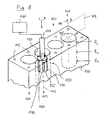
- Fig. 1 shows a schematic, oblique perspective view of a cylinder block (engine block) 100 for a 4-cylinder internal combustion engine.
- the cylinder block consisting of a cast material or of a light metal material
- four axially parallel cylinder bores 101, 102, 103, 104 are arranged at equal distances in a row next to each other arranged so that their central bore axes 111 lie in a common plane (cylinder plane 112).
- From the upper side of the cylinder block are provided internally threaded bores 115 axially parallel to the cylinder head bores so that in each case four of these bores are distributed uniformly around the circumference of a cylinder bore.
- the holes 115 are used to receive cylinder head bolts, with the help of which, after completion of the processing of the cylinder block of the associated cylinder head is screwed onto the cylinder block 100 with the interposition of a cylinder head gasket.
- the cylinder block 100 is a structurally nonuniform workpiece, in which in particular each of the cylinder bores 101-104 has a different workpiece environment, in particular with regard to the wall thickness in the region of the cylinder bores and also by different connections to the coolant channels of the engine block internal cooling system.
- the inner cylinder bores 102 and 103 of the second and third cylinders each have two adjacent cylinder bores in the cylinder plane, while the outer cylinder bores (cylinders 1 and 4) have only one inner adjacent cylinder bore and on the opposite side to thicker wall sections of the workpiece.
- the workpiece 100 formed by the cylinder block is clamped on a work table (not shown) of a honing machine, not shown, with two honing spindles, wherein only one honing spindle 120 is shown.
- the cylinder surfaces formed by the inner surfaces 130 of the cylinder bores are subjected to a quality-determining finishing on the honing machine, in which both the macro-shape of the cylinder surfaces, as well as their surface topography is produced by suitable honing processes.
- the honing machine comprises a spindle motor for rotating each of its honing spindles Honing spindle about its longitudinal axis and a lifting drive for generating a vertical movement of the honing spindle during insertion of the honing tool in the workpiece or when pulling out of the workpiece.
- the lifting drive is controlled during machining so that the honing tool executes a vertical reciprocating movement within the bore, which is superimposed on the rotational movement of the workpiece (see arrows).
- a honing tool 150 is coupled, which is a gimbal-mounted honing tool with double widening.
- the honing tool has a tool body 155 which carries on one side of its circumference a cutting group 160 formed by a single honing stone, which can be delivered or withdrawn in the radial direction to the bore inner wall by means of a not-shown cutting group delivery system.
- a set of unevenly distributed around the circumference of the honing tool guide rails 170 is provided on the tool body, which can be delivered independently of the cutting group 160 in the direction of the inner surface of the bore by means of a guide rail delivery system.
- substantially rigid guidance of the axial movement of the honing tool within the bore results parallel to the bore axis 113, so that the guide rails form an axial guide device for the honing tool.
- the feed movement of both the guide rails and the cutting group and the respectively applied feed force are independently controlled by means of a Zustellkraft-control device 180 of the honing machine, in particular the feed force of the cutting group 160 highly dynamically depending on the stroke position of the honing tool (measured along the Bore axis) and the angular position of the cutting group (in the circumferential direction) can be selectively varied in quick change.
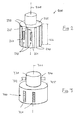
- the Fig. 2 and 4 show elements of various embodiments of inventive honing tools, which are designed especially for the processing of cylinder surfaces in cylinder blocks.
- the honing tool 200 in Fig. 2 has arranged on one side of the tool axis 201 cutting group 260 with two peripherally offset on the circumference of the tool body 255 mounted, formed by honing strips cutting material body 261 attack during honing in a pressure angle range 265 of about 45 ° on the bore inner wall.
- Their axial length is between 30% and 50% of the axial length 266 of the honing tool.
- the honing tool comprises an integrated axial guide device, which is formed in the example by a number of evenly distributed around the circumference of the honing tool guide rails 270 which are radially deliverable independently of the honing stones 261 of the cutting group 260.
- the guide rails extend substantially over the entire axial length 266 of the honing tool, the honing stones 261 are mounted in the axial central region (in other embodiments in the lower end region) of the support length defined by the guide rails.
- the honing tool 300 in Fig. 3 has arranged on one side of the tool axis 301 cutting group 360 with two peripherally offset on the circumference of the tool body 355 mounted, formed by honing strips cutting body 361 attacking during honing in an engagement angle range of about 45 ° on the bore inner wall.
- Their axial length is between 60% and 80% of the axial length of the honing tool.
- the axial guide device 370 of the honing tool comprises a guide section 371, which is attached to the spindle-side end of the tool body, with a circular-cylindrical outer surface which is located in an outside of the workpiece arranged and fixed to the honing machine guide unit 372 (upper guide) is guided axially and rotationally.
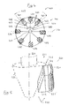
- Fig. 4 shows a guided perpendicular to the tool axis 401 section through a honing tool 400, which is a variant of the in Fig. 2 shown double-expandable honing tool is.
- the cutting group 460 mounted on one side of the tool axis 401 comprises two cutter bodies 461, 462 which are arranged offset by approximately 80 ° to 90 ° and can be controlled separately and which define an engagement angle range 465 of approximately 90 °.
- the integrated axial guide device comprises six guide rails 471-476 distributed around the circumference of the tool body, which can be delivered in the radial direction to the bore inner wall by means of a force-limited guide rail feed system 480, so as to be axially slidable within the tool, but substantially rigid within the bore axis to lead the bore.
- the guide rails consist of a hard, abrasion-resistant elastomer (Vulkollan® here), have a substantially smooth pressure surface and exert no material removal during the axially oscillating and rotating movement of the honing tool in the cylinder bore.
- the cutting group 460 is mounted on one side of the honing tool. This means, in particular, that all of the cutting material bodies standing in honing processing in material-removing engagement with the bore inner wall lie on the same side of the tool bisecting tool level 490, which contains the tool axis 401 and is perpendicular to the bisector of the cutting group 460. On the side of the cutting group is essentially only one, mounted between the cutting material body guide rails 471 and a part of the vertically aligned guide rails.
- the feed movement of the cutting material body 461 of the cutting group 460 is controlled by means of a cutting group feed system 450, which is subdivided into two independently operable subsystems.
- a Basiszustellsystem 452 has a relatively large displacement of several millimeters and serves to deliver the radial outer surfaces of the Schneidstoff emotions 461, 462 after applying the guide rails to the bore inner wall to a few microns to the bore inner wall.
- the radial position of support elements 453 of the base delivery system achieved by this adjustment movement remains unchanged during honing.
- the mechanical drive for the base delivery system is seated in the honing machine, the drive movement is achieved by suitable feed elements including a coaxially seated in the tool body Zustellkonus (see. Fig. 5 ) causes.
- a dynamic fine delivery system 454 which, starting from the radial position predetermined by the base delivery system, permits radial delivery or radial retraction of the cutting material bodies.
- Fine delivery system is designed in this way highly dynamic and allows during a single revolution of the honing tool several, eg between two and ten, periodic or aperiodic change between increase and decrease in the delivery force to complex curved and provided with a variety of local maxima and minima contours To produce the bore inner wall with high accuracy.
- the piezoelectric or otherwise driven fine delivery system can also be arranged above the Zustellkonus between this and the coarse delivery system. In this position, the fine delivery system can be arranged both on the rotating part of the honing spindle, as well as on the non-rotating part of the honing machine.
- Fig. 5 Further details of a basic delivery system and a fine delivery system are shown schematically, which also in the honing tools according to Fig. 2 or Fig. 4 can be used in the illustrated or modified manner.
- the cutting group 560 mounted on the honing tool on one side to the tool axis 501 comprises five axis-aligned honing strips 561 which are mounted on a common carrier 562 and define an overall pressure angle of approximately 30 °.
- the BasisZustellsystem 552 of the cutting group delivery system 550 includes a parallel to the tool axis axially movable cone 554.
- a piezoelectric drive element 555 of the fine delivery system 556 is attached, which is arranged between the carrier element 553 and the carrier element 562 for the honing stones.
- the radial thickness of the piezoelectric actuator 555 is determined by applying appropriate control voltages provided by the controller 180 (FIG. Fig. 1 ) are provided, radially adjustable in an adjustment range of about 20 microns to about 60 microns to possibly allow a quick change of the delivery pressure of the cutting material body.
- Fig. 6 (a) a schematic peripheral record and Fig. 6 (b) a schematic longitudinal section of the dimensions of a cylinder surface.
- radial distances of the bore inner wall from the bore axis BA are shown as a function of the circumferential position along the bore inner surface, the zero point of the circumferential direction and the 180 ° position in the cylinder plane 112 defined by the bore axes of the cylinders (cf. Fig.
- the curves R O, R M and R U respectively represent the radius in the vicinity of the upper inlet opening of the cylinder bore (R O), in the axial center portion of the cylinder bore (R M) and in the vicinity of the lower end of the cylinder bore (R U).
- curves of the circumferential letter are each related to a zero line lying concentrically to the bore axis, which in the representation in Fig. 8 each dashed line is drawn. The same radial scale in the radial direction serves for all measuring curves.
- the longitudinal letters in Fig. 6 (b) each show the course of the generatrices (parallel to the bore axis) in the selected circumferential ranges at 0 °, 90 °, 180 ° and 270 °.
- the schematic Messrume in Fig. 6 represent at the selected resolution, a substantially circular cylindrical shape of the bore inner surface with a cylindricity .DELTA.Z of about 10 microns.
- a relatively small cylindricity error is considered in some applications to be sufficient to ensure adequate sealing during operation of the internal combustion engine in conjunction with substantially circular piston rings over the entire length of the cylinder.
- a cylinder block of a series of cylinder blocks to be manufactured is clamped in the honing machine. Then, the cylinder block is braced by means of a tensioning device, which essentially simulates the clamping forces acting on the cylinder block when a cylinder head is screwed onto the cylinder block.
- the stress state of the cylinder block in the operating state can be approximately adjusted.
- a clamping device according to the patent DE 28 10 322 C2 are used, the content of which is incorporated herein by reference.
- a bracing can be made, as in the Japanese patent application JP 11 267960 is described.
- the cylinder block can still be heated significantly above ambient temperature to generally simulate the conditions of a warm, fully assembled hull engine.
- the cylinder bores of the strained and possibly heated cylinder block are honed in a single-stage or multi-stage honing process to obtain a possible circular cylindrical bore shape.
- a cylinder shape error ⁇ Z of less than 10 ⁇ m is achieved in this phase of machining.
- Typical calipers used to determine the shape of the bore can be found in Fig. 6 show characteristics shown.
- a typical machined cylinder bore has after this production step in all axial positions a substantially circular circumference with a surface contour without pronounced maxima, minima or inflection points and in the axial direction (longitudinal) at different positions along the circumference practically no or only a very slight, gradual variation of the radius or of the diameter ( Fig. 6 (b) ).
- the clamping device After completion of this phase of processing, the clamping device is removed, so that the elastic deformation produced by the clamping device and possibly by the action of temperature are reduced in the workpiece and this assumes a relaxed state.
- Fig. 7 shows an example of the corresponding Fig. 6 recorded measurement records in the circumferential direction ( Fig. 7 a ) and in the axial direction ( Fig. 7b ) of the marginal fourth cylinder bore 104 in Fig. 1 , It can be seen that the hole in the vicinity of the cylinder head side inlet side (represented by the curve R O ) has an approximately 2-fold radial symmetry about the bore axis BA, in which the largest diameter obliquely to the cylinder plane in the range of the circumferential angle 135 ° or.
- curve R M In the axial center region of the bore (curve R M ) results in a much more complex relationship between circumferential position and bore radius or bore diameter. In the example shown, approximately eight local maxima of the inner radius, which are separated by local minimums of the inner radius, result in the circumferential direction. The largest radii tend to remain inclined to the cylinder plane.
- the bore cross section is also asymmetrical, but the 2-fold radial symmetry still indicated at the cylinder head end no longer dominates and dominates an almost completely irregular bore cross-sectional shape.
- the asymmetrically warped hole shape that can be characterized in this way corresponds to a cylindricity ⁇ Z of between 30 ⁇ m and 40 ⁇ m.
- This complex and asymmetrically deformed bore geometry will be deformed when placing and screwing a cylinder head and heating the resulting hull motor in the range of operating temperatures back to a largely cylindrical bore shape, as shown by Fig. 6 was explained.
- the complexly deformed bore geometry is now measured after removal of the clamping device in order to determine in this way the local radii of the distorted shape as a function of the axial position and the circumferential position.
- a data set is determined, which represents the relaxation, complex and asymmetrically deformed bore geometry.
- This complex bore shape corresponds to a "negative mold” that is to be achieved in the machining of the other cylinder blocks of the series by shaping honing machining, if the machined cylinder bores in the mounted state of the engine should have a largely cylindrical shape with low cylindricity.
- the geometry data representing the complex unsymmetrical bore shape separately for each cylinder bore is stored in the controller 180 in a suitable form.
- honing They can be compared with measured values of a dimensional measuring system with tool-internal sensors (eg air measuring system) and converted into corresponding data for the delivery pressure with which a one-sided attached to a honing tool cutting group must be applied to axially rigid guidance of the honing tool and control of the feed force of the cutting group depending on the axial position and the angular position of the honing tool to achieve the complex asymmetrically shaped bore shape.
- tool-internal sensors eg air measuring system
- Fig. 8 shows exemplary for two axial positions of the cylinder (represented by the curves R O and R M in Fig. 8 (a) ) the stroke and rotation angle-dependent radius profile of the bore (in Fig. 8 (a) ) and in Fig. 8 (b) the course of the feed force F on the rotation angle ⁇ , respectively in the corresponding axial heights.
- the dashed curve F O represents that variation of the feed force on the rotational angle which would be required if a honing tool, rotating the cutting group in the upper end of the cylinder bore, the inner surface being processed.
- the solid line F M corresponds to the temporal variation or Angular variation that would be required in the central area of the hole (R M ).
- the cylinder bore can be measured by means of a shape measuring system.
- a possibly existing, measured difference of the actual shape from the desired shape can be used to correct the infeed system as a function of stroke position and angle of rotation.
- a measurement of the bore shape can thus be carried out for determining actual shape values, and a difference between the shape Is values and the desired shape can be processed to correct the control of the delivery force.
- the material-removing machining steps for generating the complex, non-circular and possibly asymmetrical bore shapes are produced with the aid of a honing tool (or with the aid of a plurality of honing tools used in succession), the cutting group of these honing tools being designed for a substantial material removal, around the macro-shape of the bore in the desired manner.
- This causes the microstructure of the machined Bore surface may not meet the specified requirements for operation in terms of surface roughness and / or surface structure. Therefore, in preferred methods after the predetermining processing steps at least one substantially form neutral, ie the macro-shape of the bore substantially not changing machining operation performed.
- honing tools can be used with appropriately adapted to the surface requirements grain of the cutting material body and / or brushing or Plateauhontechnikmaschinee and / or other surface structure changing processing tools, such as non-contact tools, such as laser and / or water jet generator, the surface structure of the bore inner surface without affecting the Can change macro shape.
- non-contact tools such as laser and / or water jet generator
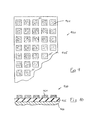
- FIGS. 9 and 10 show in plan view and cross-section, a cutting group 960, which is optimized for a "Plateauhonbearbeitung" unsymmetrical bore shapes to cut the still present after the shaping honing tips of the roughness profile and thereby increase the bearing ratio of the surface. Since in the previous processing steps a bore shape with possibly very small local radii in the range of local minima or maxima can be generated, a honing tool is provided whose cutting group 960 is capable of the corrugated surface of a targeted non-circularly machined bore with a cylindricity of to process substantially uniformly over 10 ⁇ m.
- a more segmented honing system in which the cutting material bodies 961 formed by honing stone segments are applied to an inherently elastic base body 965, for example a plate made of a rubber-like material.
- This intrinsically elastic base body is applied to the actual base material 966 of the honing stone, for example a support made of steel, copper or the like, by gluing or in some other way.
- the square honing stone segments 961 have an extension of 10mm x 10mm.
- Honing tools with one or more such cutting groups can be used regardless of the other features of the invention and the method described herein in other honing process for the final machining of holes in workpieces.
Landscapes
- Engineering & Computer Science (AREA)
- Mechanical Engineering (AREA)
- Physics & Mathematics (AREA)
- Geometry (AREA)
- Finish Polishing, Edge Sharpening, And Grinding By Specific Grinding Devices (AREA)
Claims (13)
- Procédé de rodage de la surface intérieure d'un alésage dans une pièce à usiner, en particulier de rodage d'une surface de glissement de cylindre lors de la fabrication de bloc-cylindres pour des moteurs à combustion interne, lors duquel un outil de rodage est actionné de manière à se déplacer axialement dans l'alésage et à tourner autour de son axe, un groupe de coupe placé sur l'outil de rodage et disposant d'au moins un corps de coupe pour le traitement par enlèvement de matière de la surface intérieure est appuyé à une force d'approche sur la surface intérieure, un guidage essentiellement rigide du mouvement axial de l'outil de rodage pour la réalisation d'un mouvement axial de l'outil de rodage a lieu essentiellement de façon parallèle à l'axe de perçage de l'alésage, et une commande temporellement asymétrique de la force d'approche d'un groupe de coupe disposé sur l'outil de rodage d'un côte de l'axe de l'outil est réalisée en fonction de la position angulaire et le cas échéant de la course de l'outil de rodage de telle manière que l'alésage comprend au moins dans une section axiale une forme non cylindrique circulaire qui diverge significativement d'une forme à symétrie radiale à 2 chiffres par rapport à l'axe de perçage, dans laquelle est utilisé un outil de rodage qui comprend un jeu de barres de guidage reparties sur la circonférence de l'outil de rodage pour le guidage axial de l'outil de rodage dans l'alésage, lesquelles peuvent être approchées en direction de la surface intérieure de l'alésage indépendamment du groupe de coupe, sachant que le guidage essentiellement rigide du mouvement axial est obtenu en appuyant les barres de guidage sur la surface intérieure de l'alésage pendant le mouvement de l'outil de rodage dans l'alésage.
- Procédé selon la revendication 1, sachant que des écarts de forme sont produits sur l'alésage, lesquels correspondent à une erreur de cylindricité ΔZ de plus de 10 µm, sachant que l'erreur de cylindricité ΔZ s'élève de préférence à plus de 20 µm, en particulier entre 20 µm et environ 60 µm, sachant que l'erreur de cylindricité est définie comme ΔZ=(DA-DI)/2, où DA représente le diamètre d'un cylindre touchant à l'extérieur la surface intérieure de l'alésage et DI le diamètre d'un cylindre touchant à l'intérieur la surface intérieure de l'alésage.
- Procédé selon la revendication 1 ou 2, sachant qu'est utilisé un outil de rodage présentant un seul groupe de coupe pouvant être approché séparément, lequel possède de préférence un angle d'attaque de moins de 90°, sachant que l'angle d'attaque est compris de préférence entre 1° et 70°.
- Procédé selon l'une des revendications précédentes, sachant que la commande de la force d'approche est réalisée de telle façon que la force d'approche passe par plus de deux, en particulier plus de quatre maxima et minima locaux lors d'une rotation complète de l'outil de rodage autour de l'axe de l'outil dans une zone d'alésage axiale prédéterminée.
- Procédé selon l'une des revendications précédentes, sachant que l'outil de rodage est appuyé axialement de manière coulissante par rapport au guidage essentiellement rigide du mouvement axial à l'intérieur de l'alésage et essentiellement immobile et transversalement par rapport à l'axe de l'outil.
- Procédé selon l'une des revendications précédentes, sachant qu'après l'opération de rodage formatrice permettant d'obtenir la forme d'alésage non ronde est réalisée au moins une opération de traitement essentiellement neutre au niveau de la forme pour le traitement des sections de la surface intérieure se trouvant à proximité de la surface, sachant que l'opération de traitement neutre au niveau de la forme est de préférence un traitement de rodage plateau, lors duquel des pointes du profil rugueux obtenu suite aux opérations de rodage précédentes sont coupées et/ou que lors de l'opération de traitement essentiellement neutre au niveau de la forme, la surface intérieure de l'alésage est traitée avec plusieurs corps de coupe logés de manière élastique et mobiles les uns par aux autres, lesquels présentent dans le sens axial de l'outil de rodage une extension maximale de moins de 10 % de la longueur de la zone de coupe de l'outil de rodage.
- Procédé selon l'une des revendications précédentes, sachant que pendant et/ou après une opération de rodage produisant la forme, une mesure de la forme de l'alésage est réalisée pour déterminer les valeurs réelles de la forme et qu'une différence entre les valeurs réelles de la forme et la forme théorique est traitée pour corriger la commande de la force d'approche.
- Outil de rodage, en particulier pour réaliser le procédé selon l'une des revendications précédentes, avec un corps d'outil qui définit un axe d'outil (201, 301, 401, 501), un groupe de coupe (160, 260, 360, 460, 560) placé sur le corps d'outil avec au moins un corps de coupe pour le traitement par enlèvement de matière de la surface intérieure d'un alésage, et un système d'approche du groupe de coupe (450, 550) assigné à un groupe de coupe pour exercer une force d'approche agissant radialement par rapport à l'axe de l'outil sur le corps de coupe du groupe de coupe, sachant que les corps de coupe du groupe de coupe sont disposés exclusivement sur un côté de l'outil de rodage et qu'un dispositif de guidage axial (170, 270, 370, 470) est attribué à l'outil de rodage pour le guidage essentiellement rigide du mouvement axial de l'outil de rodage de manière essentiellement parallèle par rapport à l'axe de perçage, sachant que le dispositif de guidage axial est conçu de manière à absorber la force de réaction entraînée par le groupe de coupe appuyé, caractérisé en ce que le dispositif de guidage axial comprend un jeu de barres de guidage (170, 270, 471 - 476) réparties sur la circonférence de l'outil de rodage pour le guidage axial de l'outil de rodage dans l'alésage, sachant que les barres de guidage peuvent être approchées à l'aide d'un dispositif d'approche de barres de guidage (480) indépendamment du groupe de coupe en direction de la surface intérieure de l'alésage.
- Outil de rodage selon la revendication 8, sachant que le système d'approche du groupe de coupe (450, 550) agissant sur le groupe de coupe comprend une combinaison d'un système d'approche de base (452, 552) et d'un système d'approche fine dynamique (454, 555), sachant que le système d'approche de base est conçu de préférence de telle manière que, lors d'une approche grossière, les parties du corps de coupe prélevant de la matière peuvent être approchées, à l'aide du système d'approche de base, de la surface intérieure de l'alésage via une première grande course de réglage jusqu'à un faible écart ou jusqu'au contact, et que le système d'approche fine est conçu pour produire des changements de courte durée de la force de réglage et des secondes courses de réglage relativement courtes par rapport à la première course de réglage.
- Outil de rodage selon la revendication 9, sachant que la première course de réglage du système d'approche de base s'élève à au moins un millimètre, de préférence à au moins 4 mm et que la seconde course de réglage du système d'approche fine se trouve dans la plage inférieure à 100 µm, en particulier dans la plage comprise entre 20 µm et 60 µm dans le rayon.
- Outil de rodage selon l'une des revendications 8 à 10, sachant que le système d'approche de base de l'outil de rodage est conçu pour transmettre la force d'approche d'un entraînement, de préférence mécanique ou hydraulique, disposé en dehors de l'outil de rodage et que le système d'approche fine présente au moins un entraînement, de préférence électromécanique ou piézoélectrique, disposé à l'intérieur de l'outil de rodage.
- Machine de rodage pour la réalisation du procédé selon l'une des revendications 1 à 9, avec utilisation d'un outil de rodage selon l'une des revendications 8 à 11, caractérisée par un dispositif de commande de la force d'approche pour commander la force d'approche d'un groupe de coupe disposé sur un outil de rodage en fonction de la position angulaire et le cas échéant de la course de l'outil de rodage dans un alésage, sachant que le dispositif de commande de la force d'approche (180) est configuré de telle façon que l'alésage comprend au moins dans une section axiale une forme non cylindrique circulaire qui diverge significativement d'une forme à symétrie radiale à 2 chiffres par rapport à l'axe de perçage.
- Machine de rodage selon la revendication 12, dans laquelle le dispositif de commande de la force d'approche est configuré de telle sorte que la force d'approche passe par plus de deux, en particulier plus de quatre maxima et minima locaux lors d'une rotation complète de l'outil de rodage autour de l'axe de l'outil dans une zone d'alésage axiale prédéterminée.
Priority Applications (6)
| Application Number | Priority Date | Filing Date | Title |
|---|---|---|---|
| EP20050025813 EP1790435B1 (fr) | 2005-11-25 | 2005-11-25 | Procédé de rodage d'alésages, et outil de rodage |
| EP09009260A EP2110204B1 (fr) | 2005-11-25 | 2005-11-25 | Procédé destiné à empierrer des trous de forage tout comme outil à empierrer |
| EP10010544A EP2279829B1 (fr) | 2005-11-25 | 2005-11-25 | Procédé destiné à empierrer des trous de forage tout comme outil à empierrer |
| DE200550008150 DE502005008150D1 (de) | 2005-11-25 | 2005-11-25 | Verfahren zum Honen von Bohrungen sowie Honwerkzeug hierfür |
| EP10010546.9A EP2277662B1 (fr) | 2005-11-25 | 2005-11-25 | Procédé destiné à empierrer des trous de forage tout comme outil à empierrer |
| EP10010545A EP2277661B1 (fr) | 2005-11-25 | 2005-11-25 | Procédé destiné à empierrer des trous de forage tout comme outil à empierrer |
Applications Claiming Priority (1)
| Application Number | Priority Date | Filing Date | Title |
|---|---|---|---|
| EP20050025813 EP1790435B1 (fr) | 2005-11-25 | 2005-11-25 | Procédé de rodage d'alésages, et outil de rodage |
Related Child Applications (1)
| Application Number | Title | Priority Date | Filing Date |
|---|---|---|---|
| EP09009260A Division EP2110204B1 (fr) | 2005-11-25 | 2005-11-25 | Procédé destiné à empierrer des trous de forage tout comme outil à empierrer |
Publications (2)
| Publication Number | Publication Date |
|---|---|
| EP1790435A1 EP1790435A1 (fr) | 2007-05-30 |
| EP1790435B1 true EP1790435B1 (fr) | 2009-09-16 |
Family
ID=35583420
Family Applications (5)
| Application Number | Title | Priority Date | Filing Date |
|---|---|---|---|
| EP10010545A Expired - Fee Related EP2277661B1 (fr) | 2005-11-25 | 2005-11-25 | Procédé destiné à empierrer des trous de forage tout comme outil à empierrer |
| EP10010546.9A Expired - Fee Related EP2277662B1 (fr) | 2005-11-25 | 2005-11-25 | Procédé destiné à empierrer des trous de forage tout comme outil à empierrer |
| EP10010544A Expired - Fee Related EP2279829B1 (fr) | 2005-11-25 | 2005-11-25 | Procédé destiné à empierrer des trous de forage tout comme outil à empierrer |
| EP09009260A Expired - Fee Related EP2110204B1 (fr) | 2005-11-25 | 2005-11-25 | Procédé destiné à empierrer des trous de forage tout comme outil à empierrer |
| EP20050025813 Active EP1790435B1 (fr) | 2005-11-25 | 2005-11-25 | Procédé de rodage d'alésages, et outil de rodage |
Family Applications Before (4)
| Application Number | Title | Priority Date | Filing Date |
|---|---|---|---|
| EP10010545A Expired - Fee Related EP2277661B1 (fr) | 2005-11-25 | 2005-11-25 | Procédé destiné à empierrer des trous de forage tout comme outil à empierrer |
| EP10010546.9A Expired - Fee Related EP2277662B1 (fr) | 2005-11-25 | 2005-11-25 | Procédé destiné à empierrer des trous de forage tout comme outil à empierrer |
| EP10010544A Expired - Fee Related EP2279829B1 (fr) | 2005-11-25 | 2005-11-25 | Procédé destiné à empierrer des trous de forage tout comme outil à empierrer |
| EP09009260A Expired - Fee Related EP2110204B1 (fr) | 2005-11-25 | 2005-11-25 | Procédé destiné à empierrer des trous de forage tout comme outil à empierrer |
Country Status (2)
| Country | Link |
|---|---|
| EP (5) | EP2277661B1 (fr) |
| DE (1) | DE502005008150D1 (fr) |
Cited By (6)
| Publication number | Priority date | Publication date | Assignee | Title |
|---|---|---|---|---|
| DE102013204714A1 (de) | 2013-03-18 | 2014-10-02 | Elgan-Diamantwerkzeuge Gmbh & Co. Kg | Honverfahren und Honwerkzeug |
| DE102014212941A1 (de) | 2014-07-03 | 2016-01-07 | Elgan-Diamantwerkzeuge Gmbh & Co. Kg | Honwerkzeug und Honverfahren |
| DE102014225164A1 (de) | 2014-12-08 | 2016-06-09 | Elgan-Diamantwerkzeuge Gmbh & Co. Kg | Feinbearbeitungsverfahren zum Herstellen einer rotationssymmetrischen Bohrung mit axialem Konturverlauf |
| DE102015203052A1 (de) | 2015-02-20 | 2016-08-25 | Elgan-Diamantwerkzeuge Gmbh & Co. Kg | Honverfahren zum Formhonen |
| DE102015203051A1 (de) | 2015-02-20 | 2016-08-25 | Elgan-Diamantwerkzeuge Gmbh & Co. Kg | Honverfahren und Bearbeitungsmaschine zum Formhonen |
| CN110520247A (zh) * | 2017-02-17 | 2019-11-29 | 埃尔甘-钻石工具有限责任两合公司 | 珩磨工具和在使用该珩磨工具时的精加工方法 |
Families Citing this family (23)
| Publication number | Priority date | Publication date | Assignee | Title |
|---|---|---|---|---|
| DE102006062665A1 (de) * | 2006-12-29 | 2008-07-03 | Gehring Gmbh & Co. Kg | Verfahren zur formändernden Bearbeitung einer Bohrung |
| DE102007024569A1 (de) * | 2007-05-25 | 2008-11-27 | Daimler Ag | Verfahren zur Herstellung von Bohrungen in Gehäusen, insbesondere von Zylinderbohrungen für Hubkolbenmaschinen in Zylinderkurbelgehäusen |
| DE102007038123B4 (de) | 2007-08-04 | 2010-06-10 | Gehring Technologies Gmbh | Maschine zur Erzeugung nicht zylindrischer Bohrungsflächen |
| DE102007063567A1 (de) | 2007-12-31 | 2009-07-09 | Daimler Ag | Verfahren zur Erzeugung einer nichtzylindrischen Bohrungsfläche in einem Werkstück durch Formhonen |
| DE102008064592B4 (de) | 2008-12-30 | 2014-08-28 | Gehring Technologies Gmbh | Vorrichtung zur Erzeugung einer nicht zylindrischen Innenfläche einer Bohrung |
| DE102009010791B4 (de) * | 2009-02-26 | 2019-07-18 | Daimler Ag | Zylinderbohrung eines Hubkolbenmotors |
| DE102009051262A1 (de) | 2009-10-29 | 2011-05-12 | Daimler Ag | Verfahren zur Herstellung einer thermisch gespritzten Zylinderlaufbahn für Verbrennungsmotoren |
| DE102009051258A1 (de) | 2009-10-29 | 2010-06-17 | Daimler Ag | Verfahren und Honwerkzeug zur Herstellung zumindest einer Lagerbohrung und Verbrennungsmotor mit zumindest einer gehonten Lagerbohrung |
| DE102010032453B4 (de) | 2010-07-28 | 2014-04-24 | Gehring Technologies Gmbh | Honwerkzeug und Verfahren zum äquidistanten Glätten einer Zylinderbohrung |
| DE102010052271B4 (de) | 2010-11-23 | 2019-05-16 | Fraunhofer-Gesellschaft zur Förderung der angewandten Forschung e.V. | Honwerkzeug und Verfahren zum Honen der Innenfläche einer Bohrung in einem Werkstück |
| DE102011089462B4 (de) | 2011-12-21 | 2015-09-10 | Nagel Maschinen- Und Werkzeugfabrik Gmbh | Feinbearbeitungsmaschine, Kupplungseinrichtung für Feinbearbeitungsmaschine und Bearbeitungswerkzeug |
| DE102012009110B4 (de) * | 2012-04-26 | 2014-05-28 | Gebr. Heller Maschinenfabrik Gmbh | Honwerkzeug |
| DE102013103843A1 (de) | 2013-04-16 | 2014-10-16 | Audi Ag | Verfahren zur Herstellung einer Werkstückoberfläche |
| DE102013220507B4 (de) * | 2013-10-11 | 2015-11-05 | Gehring Technologies Gmbh | Vorrichtung und Verfahren zur Erzeugung einer nicht zylindrischen Innenfläche einer Bohrung |
| CN107735202B (zh) * | 2015-05-26 | 2019-04-09 | 格林技术有限公司 | 用于利用珩磨工具制造旋转对称的、非柱形孔的方法 |
| CN105234800B (zh) * | 2015-08-25 | 2018-03-13 | 上海交通大学 | 一种具备非圆异型孔加工功能的珩磨刀具装置 |
| DE102015216531A1 (de) * | 2015-08-28 | 2017-03-02 | MAPAL Fabrik für Präzisionswerkzeuge Dr. Kress KG | Aussteuerwerkzeug |
| DE102016200295A1 (de) | 2016-01-13 | 2017-07-13 | Kadia Produktion Gmbh + Co. | Honmaschine |
| DE102017221316A1 (de) | 2017-11-28 | 2019-05-29 | Nagel Maschinen- Und Werkzeugfabrik Gmbh | Honverfahren und Honmaschine zur Durchführung des Honverfahrens |
| DE102018206113A1 (de) | 2018-04-20 | 2019-10-24 | Elgan-Diamantwerkzeuge Gmbh & Co. Kg | Feinbearbeitungsverfahren zum Herstellen einer nicht-kreiszylindrischen Bohrung sowie Feinbearbeitungssystem und Schleifwerkzeugeinheit |
| CN112959204B (zh) * | 2021-03-09 | 2023-11-17 | 苏州航发航空零部件有限公司 | 汽车发动机气缸内孔网纹的专用珩磨加工材料及加工工艺 |
| CN113492355B (zh) * | 2021-05-07 | 2022-06-07 | 南京航空航天大学 | 一种液压偶件精密珩磨孔径预测及控制方法 |
| CN114833712B (zh) * | 2022-04-18 | 2023-03-21 | 南京航空航天大学 | 一种实时调节珩磨压力的控制系统及其运行工艺 |
Family Cites Families (8)
| Publication number | Priority date | Publication date | Assignee | Title |
|---|---|---|---|---|
| DE2619741C2 (de) * | 1976-05-05 | 1985-12-05 | Maschinenfabrik Gehring Gmbh & Co Kg, 7302 Ostfildern | Zustellvorrichtung für ein Zerspanwerkzeug zum Bearbeiten von Werkstückbohrungen, insbesondere ein Honwerkzeug |
| DE2810322C2 (de) | 1978-03-10 | 1982-11-25 | Peter 7442 Neuffen Nagel | Honmaschine |
| DE3042755A1 (de) * | 1980-11-13 | 1982-05-19 | Peter 7442 Neuffen Nagel | Verfahren und vorrichtung zur bearbeitung von werkstuecken mit mehreren bearbeitungsstationen |
| DE3932328A1 (de) * | 1989-09-28 | 1991-04-11 | Opel Adam Ag | Verfahren zur bearbeitung von durch reibung hochbeanspruchten flaechen in brennkraftmaschinen und vorrichtung zur durchfuehrung des verfahrens |
| JPH11267960A (ja) | 1998-03-20 | 1999-10-05 | Nissan Motor Co Ltd | 孔加工装置 |
| JP4193086B2 (ja) * | 1999-04-08 | 2008-12-10 | 日産自動車株式会社 | シリンダボアの加工方法および加工装置 |
| EP1321229B1 (fr) | 2001-12-20 | 2009-04-08 | Gehring GmbH & Co. KG | Procédé pour l'usinage d'une forure |
| DE10315218B4 (de) * | 2003-04-01 | 2010-12-30 | Nagel Maschinen- Und Werkzeugfabrik Gmbh | Verfahren und Vorrichtung zur Feinbearbeitung einer Oberfläche eines Werkstücks |
-
2005
- 2005-11-25 EP EP10010545A patent/EP2277661B1/fr not_active Expired - Fee Related
- 2005-11-25 EP EP10010546.9A patent/EP2277662B1/fr not_active Expired - Fee Related
- 2005-11-25 EP EP10010544A patent/EP2279829B1/fr not_active Expired - Fee Related
- 2005-11-25 EP EP09009260A patent/EP2110204B1/fr not_active Expired - Fee Related
- 2005-11-25 DE DE200550008150 patent/DE502005008150D1/de active Active
- 2005-11-25 EP EP20050025813 patent/EP1790435B1/fr active Active
Cited By (9)
| Publication number | Priority date | Publication date | Assignee | Title |
|---|---|---|---|---|
| DE102013204714A1 (de) | 2013-03-18 | 2014-10-02 | Elgan-Diamantwerkzeuge Gmbh & Co. Kg | Honverfahren und Honwerkzeug |
| DE202014010306U1 (de) | 2013-03-18 | 2015-03-06 | Elgan-Diamantwerkzeuge Gmbh & Co. Kg | Honwerkzeug |
| DE102014212941A1 (de) | 2014-07-03 | 2016-01-07 | Elgan-Diamantwerkzeuge Gmbh & Co. Kg | Honwerkzeug und Honverfahren |
| WO2016001014A1 (fr) * | 2014-07-03 | 2016-01-07 | Elgan-Diamantwerkzeuge Gmbh & Co. Kg | Outil et procédé de rodage |
| DE102014225164A1 (de) | 2014-12-08 | 2016-06-09 | Elgan-Diamantwerkzeuge Gmbh & Co. Kg | Feinbearbeitungsverfahren zum Herstellen einer rotationssymmetrischen Bohrung mit axialem Konturverlauf |
| DE102014225164B4 (de) * | 2014-12-08 | 2017-10-12 | Elgan-Diamantwerkzeuge Gmbh & Co. Kg | Feinbearbeitungsverfahren zum Herstellen einer rotationssymmetrischen Bohrung mit axialem Konturverlauf |
| DE102015203052A1 (de) | 2015-02-20 | 2016-08-25 | Elgan-Diamantwerkzeuge Gmbh & Co. Kg | Honverfahren zum Formhonen |
| DE102015203051A1 (de) | 2015-02-20 | 2016-08-25 | Elgan-Diamantwerkzeuge Gmbh & Co. Kg | Honverfahren und Bearbeitungsmaschine zum Formhonen |
| CN110520247A (zh) * | 2017-02-17 | 2019-11-29 | 埃尔甘-钻石工具有限责任两合公司 | 珩磨工具和在使用该珩磨工具时的精加工方法 |
Also Published As
| Publication number | Publication date |
|---|---|
| EP2277661A1 (fr) | 2011-01-26 |
| EP2110204B1 (fr) | 2012-04-25 |
| EP2277661B1 (fr) | 2012-12-26 |
| DE502005008150D1 (de) | 2009-10-29 |
| EP1790435A1 (fr) | 2007-05-30 |
| EP2279829B1 (fr) | 2012-06-06 |
| EP2277662A1 (fr) | 2011-01-26 |
| EP2279829A1 (fr) | 2011-02-02 |
| EP2277662B1 (fr) | 2013-09-25 |
| EP2110204A1 (fr) | 2009-10-21 |
Similar Documents
| Publication | Publication Date | Title |
|---|---|---|
| EP1790435B1 (fr) | Procédé de rodage d'alésages, et outil de rodage | |
| EP2976184B1 (fr) | Procédé de rodage et outil de rodage | |
| EP1907156B1 (fr) | Procede d'usinage de precision d'arbres-manivelles et centre d'usinage correspondant | |
| EP1815944B1 (fr) | Méthode et appareil pour rectifier des trous d'alésage. | |
| EP2170556B1 (fr) | Machine pour la production de faces d'alésage non cylindriques | |
| EP2654986B1 (fr) | Procédé d'usinage et outil d'usinage pour l'usinage de surfaces de pièces courbes | |
| EP3164244B1 (fr) | Outil et procédé de rodage | |
| WO2004012903A1 (fr) | Procede et dispositif pour rectifier un element de machine a symetrie de revolution | |
| EP2551055A2 (fr) | Procédé et installation d'usinage de précision d'un perçage de palier d'un vilebrequin | |
| DE102009030856A1 (de) | Verfahren und Vorrichtung zur endmaßgenauen Bearbeitung von Kurbel- oder Nockenwellen | |
| DE102010010901A1 (de) | Verfahren und Vorrichtung zum Feinbearbeiten einer Kurbelwellenlagerbohrung | |
| DE102007063567A1 (de) | Verfahren zur Erzeugung einer nichtzylindrischen Bohrungsfläche in einem Werkstück durch Formhonen | |
| EP2679324A2 (fr) | Outils et procédé permettant de rendre mécaniquement un objet rugueux | |
| EP1815943A1 (fr) | Méthode et appareil pour rectifier des trous d'alésage. | |
| DE102011079757A1 (de) | Bearbeitungsverfahren und Bearbeitungswerkzeug zum Bearbeiten einer gekrümmten Werkstückoberfläche sowie Werkstück | |
| EP3781352A1 (fr) | Procédé d'usinage de précision permettant de fabriquer un trou non cylindrique circulaire ainsi que système d'usinage de précision et unité d'outil de meulage | |
| EP2828035A1 (fr) | Carter de moteur pourvu d'un alésage pour un moteur à combustion interne | |
| DE102014225164B4 (de) | Feinbearbeitungsverfahren zum Herstellen einer rotationssymmetrischen Bohrung mit axialem Konturverlauf | |
| DE102006002523A1 (de) | Verfahren zum Feinarbeiten von Bohrungen sowie Deformationseinrichtung hierfür | |
| DE202009008879U1 (de) | Vorrichtung zur endmaßgenauen Bearbeitung von Kurbel- oder Nockenwellen |
Legal Events
| Date | Code | Title | Description |
|---|---|---|---|
| PUAI | Public reference made under article 153(3) epc to a published international application that has entered the european phase |
Free format text: ORIGINAL CODE: 0009012 |
|
| AK | Designated contracting states |
Kind code of ref document: A1 Designated state(s): AT BE BG CH CY CZ DE DK EE ES FI FR GB GR HU IE IS IT LI LT LU LV MC NL PL PT RO SE SI SK TR |
|
| AX | Request for extension of the european patent |
Extension state: AL BA HR MK YU |
|
| 17P | Request for examination filed |
Effective date: 20070621 |
|
| 17Q | First examination report despatched |
Effective date: 20070723 |
|
| AKX | Designation fees paid |
Designated state(s): DE |
|
| GRAP | Despatch of communication of intention to grant a patent |
Free format text: ORIGINAL CODE: EPIDOSNIGR1 |
|
| RTI1 | Title (correction) |
Free format text: METHOD OF HONING OF BORES AND HONING TOOL THEREFOR |
|
| GRAS | Grant fee paid |
Free format text: ORIGINAL CODE: EPIDOSNIGR3 |
|
| GRAA | (expected) grant |
Free format text: ORIGINAL CODE: 0009210 |
|
| AK | Designated contracting states |
Kind code of ref document: B1 Designated state(s): DE |
|
| REF | Corresponds to: |
Ref document number: 502005008150 Country of ref document: DE Date of ref document: 20091029 Kind code of ref document: P |
|
| PLBE | No opposition filed within time limit |
Free format text: ORIGINAL CODE: 0009261 |
|
| STAA | Information on the status of an ep patent application or granted ep patent |
Free format text: STATUS: NO OPPOSITION FILED WITHIN TIME LIMIT |
|
| 26N | No opposition filed |
Effective date: 20100617 |
|
| PGFP | Annual fee paid to national office [announced via postgrant information from national office to epo] |
Ref country code: DE Payment date: 20221124 Year of fee payment: 18 |
|
| P01 | Opt-out of the competence of the unified patent court (upc) registered |
Effective date: 20230523 |