EP1785561A1 - Vorrichtung für das Öffnen und das Schliessen der Tür eines Lastkraftwagens, eines Anhängers, oder ähnliches - Google Patents
Vorrichtung für das Öffnen und das Schliessen der Tür eines Lastkraftwagens, eines Anhängers, oder ähnliches Download PDFInfo
- Publication number
- EP1785561A1 EP1785561A1 EP05425800A EP05425800A EP1785561A1 EP 1785561 A1 EP1785561 A1 EP 1785561A1 EP 05425800 A EP05425800 A EP 05425800A EP 05425800 A EP05425800 A EP 05425800A EP 1785561 A1 EP1785561 A1 EP 1785561A1
- Authority
- EP
- European Patent Office
- Prior art keywords
- lever
- base
- pawl element
- door
- upper abutment
- Prior art date
- Legal status (The legal status is an assumption and is not a legal conclusion. Google has not performed a legal analysis and makes no representation as to the accuracy of the status listed.)
- Granted
Links
Images


Classifications
-
- E—FIXED CONSTRUCTIONS
- E05—LOCKS; KEYS; WINDOW OR DOOR FITTINGS; SAFES
- E05B—LOCKS; ACCESSORIES THEREFOR; HANDCUFFS
- E05B83/00—Vehicle locks specially adapted for particular types of wing or vehicle
- E05B83/02—Locks for railway freight-cars, freight containers or the like; Locks for the cargo compartments of commercial lorries, trucks or vans
- E05B83/08—Locks for railway freight-cars, freight containers or the like; Locks for the cargo compartments of commercial lorries, trucks or vans with elongated bars for actuating the fastening means
- E05B83/10—Rotary bars
Definitions
- the present invention relates to a door sill-mounted device for opening and closing the door of the body of trucks, trailers and the like.
- Devices for opening and closing the doors of trucks are currently made of materials such as steel or cast iron and are suitably sized in order to ensure optimum mechanical strength and maximum durability.
- Meeting these requirements entails the use of a sufficient amount of raw material, the cost of which considerably affects the overall production cost of the items being considered; further, the manufacture of these products entails programming a series of cycles which entail the manufacture of respective intermediate components, with the consequent use of various devices and machine tools.
- these traditional production technologies currently affect the final cost of the object to a substantial extent which is no longer acceptable in relation to current market requirements.
- the aim of the present invention is to obviate the above-cited drawbacks and meet the above-mentioned requirements, by providing a door sill-mounted device for opening and closing the door of the body of trucks, trailers and the like which, while offering optimum characteristics of strength and durability, can be manufactured with a smaller amount of raw materials and with a smaller number of cycles, so as to limit the so-called lead time.
- an object of the present invention is to provide a door sill-mounted device for opening and closing the door of the body of trucks, trailers and the like which can be opened easily by the operator with just one hand.
- Another object of the present invention is to provide a door sill-mounted device for opening and closing the door of the body of trucks, trailers and the like which can be closed effectively and easily even in conditions in which the door or lever are not in the correct position.
- Another object of the present invention is to provide a structure which is simple, relatively easy to provide in practice, safe in use, effective in operation, and has a relatively low cost.
- a door sill-mounted device for opening and closing the door of the body of trucks, trailers and the like, characterized in that it comprises at least one base, which is rigidly coupled to the framework of the body below the door and is provided with anchoring means for at least one lever, which is keyed rigidly at the lower end of at least one rod which is supported rotatably in said door, and at least one upper abutment, which is rigidly coupled to the framework of the body, for at least one pawl element, which is fixed to the upper end of said rod, said lever being manually rotatable from at least one angular position for closing the door, in which it is engaged in said anchoring means and in which said pawl element is rigidly coupled to said upper abutment monolithically with said lever, to at least one angular position for freely opening the door, in which it is disengaged from said anchoring means and in which said pawl element is disengaged from said upper abutment monolithically with said lever, said lever being provided with
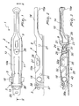
- the reference numeral 1 generally designates a door sill-mounted device for opening and closing the door of the body of trucks, trailers and the like according to the invention.
- the door sill-mounted device comprises at least one base 2, which is rigidly coupled to the framework of the body below the door and is provided with anchoring means 3 for at least one lever 4, which is keyed rigidly substantially at the lower end of at least one rod 5, which is supported rotatably in said door.
- the device further comprises at least one upper abutment 6, which is rigidly coupled to the framework of the body, for at least one pawl element 7, which is fixed to the upper end of the rod 5.
- the lever 4 can be turned manually in both directions from at least one angular position for the complete closure of the door (in which it is shown in all the accompanying figures), in which it is engaged within the anchoring means 3 and in which, monolithically therewith, the pawl element 7 is coupled to the upper abutment 6, to at least one angular position for freely opening the door, in which it is disengaged from the anchoring means 3, and in which, monolithically therewith, the pawl element 7 is disengaged from the upper abutment 6.
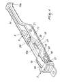
- the lever 4 is conveniently provided with means 8 for safety coupling to the base 2 (see in particular Figure 3); said coupling means are adapted in particular to prevent the accidental disengagement of the lever 4 from the base 2, and conveniently can be actuated easily by means of at least one button 9 with the same hand with which the lever 4 is turned.
- the base 2, the lever 4, the pawl element 7 and the upper abutment 6 have a substantially laminar shape, which is conveniently contoured so as to minimize their weight and at the same time optimize their mechanical strength and rigidity characteristics. In addition to minimizing weight, in this manner a substantial containment of the use of raw material is also achieved.
- the lever 4 is conveniently and preferably made of a material such as steel plate, with a thickness chosen appropriately in order to withstand the typical stresses to which the device is subjected; as an alternative, it is possible however to use other materials having equivalent mechanical characteristics.
- the lever 4 has a transverse cross-section which is substantially shaped like an inverted letter U, with a geometry which can vary from one end to the other, so as to form an upper surface 10 and two mutually opposite contoured sides 11, 12; the upper surface 10 further forms a longitudinal stiffening ridge 10a. In this manner, the weight and the use of material are minimized. In particular, the extent of the upper surface 10 and of the contoured sides 11, 12 can vary from one end to the other.
- the lever 4 forms, at its mutually opposite ends, an end lug 13, which is adapted to engage in the anchoring means 3, and a terminal grip portion 14, which is contoured so as to form at least one sort of receptacle 15, which is adapted to accommodate a sort of insert 15a for protecting the hands of the operator.
- the insert 15a is made for example of a synthetic material such as plastics or other materials having equivalent characteristics.
- the lever 4 forms positively a sort of perimetric border 16, which connects the upper surface 10 and the contoured sides 11 and 12 and which, if sized appropriately, is adapted to give the lever 4 optimum strength and rigidity (increasing the resisting cross-section without increasing significantly the weight of said part).
- the contoured sides 11, 12 of the lever 4 form respective mutually opposite and coaxial first keying holes 17 for the rod 5, in which a first portion 18, which is tubular with riveted ends (or has another cross-section adapted to prevent rotation), is fixed; the rod 5 is inserted and locked in said portion by way of connecting elements of the type with an exposed pin (not shown), or of the type with a concealed (effraction-resistant) pin, or by welding.
- the pin-based connection in particular, allows to disassemble quickly and easily the rod 5 from the lever 4 for maintenance, part replacement, and other operations.
- Circular coaxial holes 19 are provided in the sides 11 and 12 for the insertion of at least one transverse pin 20, the function of which will be explained hereinafter; the pin 20 further stiffens and strengthens the lever 4.
- the means 8 for the safety coupling of the lever 4 to the base 2 comprise, as mentioned above, at least one button 9, which is supported rotatably on at least one respective pin 21, which is fixed, at its ends, to the contoured sides 11, 12 of the lever 4.
- the button 9 forms an extension 22, which ends with a sort of tooth 23, and a protrusion 24; the button 9 can rotate advantageously, about the pivot 21, from a position for restraining the lever 4, in which the tooth 23 is engaged in the base 2 (as explained hereinafter), to a position for releasing the lever 4, in which the tooth 23 is disengaged from the base 2 so as to allow the free rotation of the lever 4.
- the possibility to open the device with just one hand (grip on the lever 4 and actuation of the button 9 preferably with the thumb) is particularly advantageous, since it facilitates and simplifies loading and unloading operations and allows them to be faster.
- the safety coupling means 8 conveniently comprise two torsion springs (not shown for the sake of clarity in the figures, but of a substantially known and traditional type), which are keyed along the pin 21 on opposite sides and are adapted to keep the button elastically in the position for restraining the lever 4.
- Each one of the torsion springs has a first end which is associated with the button 9 and a second end which abuts against the lever 4. Fitting two torsion springs associated with the button 9 allows to keep said button elastically in the coupling position even if one of the two springs breaks.
- the lever 4 forms a substantially circular hole 25, at which at least one key-operated safety detent 26 is fitted in order to retain the button 9 in said position for restraining the lever 4, said detent being adapted, in particular, to abut at the protrusion 24 of the button 9, so that said button cannot be turned except by actuating said detent with its own key.
- the lever 4 is affected, at the longitudinal ridge 10a, by two first through holes 27 and 28, the function of which will be explained hereinafter.
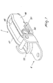
- the base 2 is conveniently and preferably made of a material such as steel plate, or of another material having equivalent characteristics, whose thickness is sized appropriately in order to withstand the typical stresses to which the device is subjected.
- the base 2 is affected by at least three circular holes 29 for fixing, by means of screws, to the body of the truck (not shown in the figures), said screws being concealed, when the device is fitted, by the lever 4 in the angular closure position.
- the base 2 is affected, substantially at one of its ends, by an opening 30, which is substantially shaped like a capital letter D and in which the straight side is constituted by a raised rim 31, in which the tooth 23 of the button 9 is adapted to engage in such position for restraining the lever 4 to the base 2.
- the direction of the rotation of the button 9 about the pin 21 allows to achieve the maximum assurance of closure against any accidental and unexpected event: any impact against the button in fact evidently acts in the direction for closing the device, i.e., it facilitates the engagement of the tooth 23 below the rim 31.
- the button 9 is provided with minimal space occupation, such as to not protrude from the profile of the lever 4, so as to remain perfectly protected against any transverse impacts.
- the release of the button 9 occurs by pressing with a finger substantially parallel to the lever 4 (transversely), not at right angles thereto, as occurs in all known traditional devices.
- the base 2 comprises second through holes 32, 32a, which are adapted to be arranged, when the lever 4 is in the angular closure position, below the longitudinal ridge 10a and adjacent to the first through holes 27, 28, so that it is possible to fix thereto customs seals and the like, not shown in the figures.
- the second through holes 32, 32a are provided in a plate 33, which is inserted in a respective slot 34 provided in the base 2 and comprises a terminal portion 35, which is substantially folded at right angles, for fixing to the base 2, for example by means of at least one rivet; at the slot 34, the base 2 in fact forms a sort of protrusion 36 below which the folded portion 35 is arranged.
- the means 3 for anchoring the end lug 13 of the lever 4 conveniently comprise at least one bracket 37, which has a substantially U-shaped transverse cross-section and is affected at its ends by two mutually opposite coaxial holes, in which a first cross-member 38 is locked; the lug 13 engages below said cross-member when the lever 4 is in the angular closure position; the bracket 37 is fixed conveniently to the base 2 by way of at least one pair of rivets 38a, which can engage in fixing holes 38b and 38c ( Figure 6).
- the base 2 conveniently comprises first elements for retaining the lever 4 in said angular closure position, in a substantially vertical direction, which are generally designated by the reference numeral 39, and first elements for retaining the lever 4 in the angular closure position, in a substantially horizontal direction, generally designated by the reference numeral 40 (reference should be made to Figure 5 among the others).
- the first elements 39 for retaining the lever 4 in a vertical direction comprise conveniently two first mutually opposite lateral flaps 41, 42, which are shaped by the base 2 and are folded substantially at right angles thereto and expand from one end of the base 2 to the other; the first lateral flaps 41, 42 are adapted to engage respectively at the contoured sides 11, 12 of the lever 4 and in particular inside them, so as to prevent their accidental movements in a vertical direction. Further, the coupling of the first lateral flaps 41, 42 to the contoured lateral sides 11, 12 allows to close the device in critical conditions in which the lever 4 is not perfectly aligned vertically with the base 2 (for example when the inclined arrangement of the vehicle produces a slight rotation of the door caused by the plays in the connections, or other similar situations).
- the first elements 40 for retaining the lever 4 in a horizontal direction favorably comprise two first recesses 43, 44, which are provided in the first contoured flaps 41, 42 and in which the pin 20 is adapted to engage transversely; this allows to prevent, when the lever 4 is in the closure position, accidental displacements in a horizontal direction. Further, the closure of the device is facilitated even in conditions in which the lever 4 is not perfectly aligned horizontally with the base 2.
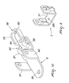
- the pawl element 7 ( Figures 7, 8 and 9) is preferably and advantageously made of a material such as steel plate. It has a transverse cross-section which is shaped substantially like an inverted letter U with a geometry which can vary from one end to the other and with an appropriately sized thickness, so as to form an upper face 45 and two contoured side walls 46, 47.
- the pawl element 7 advantageously forms a sort of perimetric contour 48, which blends the upper face 45 to the contoured side walls 46 and 47 and helps to give optimum strength and rigidity to the part while maintaining a reduced weight thereof.
- the contoured side walls 46, 47 of the pawl element 7 form respective second holes 49 for keying the rod 5, which are mutually opposite and coaxial and inside which a second tubular portion 50 is fixed: in the second tubular portion 50, the rod 5 is inserted and locked by way of connecting elements of the type with an exposed pin (not shown) or of the type with a concealed pin (effraction-resistant), or by welding.
- the pin means in particular, allow to disassemble easily and quickly the rod 5 for maintenance, part replacement, and the like.
- contoured side walls 46, 47 are affected by respective second recesses 51, 52, both of which are substantially shaped like an inverted letter V with a rounded vertex.
- the pawl element 7 forms a sort of tapered beak 53, which is adapted to engage in the upper abutment 6.
- the upper abutment 6 is conveniently made of a material such as steel plate of appropriate thickness.
- the upper abutment 6 is fixed to the framework of the body of the truck preferably by means of adapted screws, not shown in the figures, which are engaged in two holes 54 provided at the ends of said upper abutment 6 ( Figure 10).
- the upper abutment 6 positively comprises second elements for retaining, in the angular closure position, the pawl element 7 in a horizontal direction, which are generally designated by the reference numeral 55, and second elements for retaining, in the same angular closure position, the pawl element 7 in a vertical direction, which are generally designated by the reference numeral 56.
- the second elements 55 for retaining in a horizontal direction the pawl element 7 comprise two contoured protrusions 57 and 58, which are shaped substantially like an inverted letter V in which the ends are rigidly coupled to the surface of the upper abutment 6.
- the second V-shaped protrusions 55, 56 are adapted to engage respectively in the second recesses 51, 52 of the contoured side walls 46, 47, so that accidental movements thereof in a horizontal direction can be prevented.
- Each one of the substantially V-shaped protrusions 55, 56 is shaped starting from a portion of the upper abutment 6, which is cut along two parallel sides and is deformed plastically.
- the second elements 56 for retention in a vertical direction comprise two mutually opposite second terminal flaps 59, 60, which are formed by the upper abutment 6 and are folded substantially at right angles thereto and are curved; the second terminal flaps 59, 60 are conveniently adapted to engage at the end of the pawl element 7 which lies opposite the beak 53, so that accidental movements thereof in a vertical direction are prevented and centering thereof is facilitated.
- the particular shape of the second retention elements 55, 56 advantageously allows to fasten the device even in critical conditions of the positioning of the door with respect to the body in which the pawl element 7 is not perfectly aligned with the upper abutment 6.
- the upper abutment 6 forms a pair of wings 61, 62, which are substantially flat and parallel and mutually opposite and are designed to fix the ends of a second cross-member 63, below which the beak 53 of the pawl element 7 is adapted to engage in the angular position for closing the door.
- the wings 61, 62 form respectively guides 64 which are bent for the easy insertion of the beak 53 below the cross-member 63.
- the device thus provided has an extremely low weight, a need which is increasingly felt in the field of goods transportation, yet maintains high mechanical characteristics of strength and durability; the particular shape of the lever is such that any stress acts so as to facilitate the closure of the device and reduces drastically the risk of accidental opening.
- the device can be manufactured at costs which are significantly lower than those which characterize currently commercially available door sill-mounted closure devices, by means of the substantial saving in the use of raw material and in the production cycle: its manufacture by using steel plate, preferably obtained by stamping or equivalent technologies, passes through the production of a single intermediate components, instead of a plurality of intermediate components (each one for each processing step), as occurs for traditional products.
- the device can be actuated for opening and closing the door by using a single hand, typically by gripping the grip portion of the lever and by acting on the button with the thumb of the same hand, decisively facilitating the operations for loading and unloading goods on the part of the operator.
- the device can be closed easily even in situations, which are actually rather infrequent, in which the alignment between the lever and the base, and respectively between the pawl element and the upper abutment, is not perfect.
Priority Applications (6)
| Application Number | Priority Date | Filing Date | Title |
|---|---|---|---|
| AT05425800T ATE454520T1 (de) | 2005-11-14 | 2005-11-14 | Vorrichtung für das öffnen und das schliessen der tür eines lastkraftwagens, eines anhängers, oder ähnliches |
| DK05425800.9T DK1785561T3 (da) | 2005-11-14 | 2005-11-14 | Dørfodstykkemonteret indretning til åbning og lukning af døre i vognkasser på lastvogne, anhængere og lignende |
| ES05425800T ES2335779T3 (es) | 2005-11-14 | 2005-11-14 | Dispositivo montado en el umbral de una puerta para la apertura y el cierre de la puerta de la carroceria de camiones, remolques y similares. |
| PL05425800T PL1785561T3 (pl) | 2005-11-14 | 2005-11-14 | Urządzenie montowane na progu drzwi do otwierania i zamykania drzwi nadwozia samochodów ciężarowych, przyczep i tym podobnych |
| DE602005018793T DE602005018793D1 (de) | 2005-11-14 | 2005-11-14 | Vorrichtung für das Öffnen und das Schliessen der Tür eines Lastkraftwagens, eines Anhängers, oder ähnliches |
| EP05425800A EP1785561B1 (de) | 2005-11-14 | 2005-11-14 | Vorrichtung für das Öffnen und das Schliessen der Tür eines Lastkraftwagens, eines Anhängers, oder ähnliches |
Applications Claiming Priority (1)
| Application Number | Priority Date | Filing Date | Title |
|---|---|---|---|
| EP05425800A EP1785561B1 (de) | 2005-11-14 | 2005-11-14 | Vorrichtung für das Öffnen und das Schliessen der Tür eines Lastkraftwagens, eines Anhängers, oder ähnliches |
Publications (2)
| Publication Number | Publication Date |
|---|---|
| EP1785561A1 true EP1785561A1 (de) | 2007-05-16 |
| EP1785561B1 EP1785561B1 (de) | 2010-01-06 |
Family
ID=36297695
Family Applications (1)
| Application Number | Title | Priority Date | Filing Date |
|---|---|---|---|
| EP05425800A Not-in-force EP1785561B1 (de) | 2005-11-14 | 2005-11-14 | Vorrichtung für das Öffnen und das Schliessen der Tür eines Lastkraftwagens, eines Anhängers, oder ähnliches |
Country Status (6)
| Country | Link |
|---|---|
| EP (1) | EP1785561B1 (de) |
| AT (1) | ATE454520T1 (de) |
| DE (1) | DE602005018793D1 (de) |
| DK (1) | DK1785561T3 (de) |
| ES (1) | ES2335779T3 (de) |
| PL (1) | PL1785561T3 (de) |
Cited By (7)
| Publication number | Priority date | Publication date | Assignee | Title |
|---|---|---|---|---|
| WO2010057536A1 (fr) * | 2008-11-24 | 2010-05-27 | Pommier Furgocar S.R.L. | Poignee d'ouverture et de fermeture de porte telle que celle de caisson isotherme |
| EP2666935A1 (de) * | 2012-05-21 | 2013-11-27 | Pastore & Lombardi S.r.l. | Vorrichtung zum Abschließen der Türen von Fahrzeugen |
| EP3109386A1 (de) * | 2015-06-24 | 2016-12-28 | Pastore & Lombardi S.p.A. | Anordnung zum abschliessen der türen von kraftahrzeugen |
| EP2733288A3 (de) * | 2012-11-20 | 2017-11-22 | F. Hesterberg & Söhne GmbH & Co. KG | Drehstangenverschluss, insbesondere für Schwenktüren von Kraftfahrzeugaufbauten |
| EP2746505A3 (de) * | 2012-12-21 | 2017-12-13 | F. Hesterberg & Söhne GmbH & Co. KG | Drehstangenverschluss, insbesondere für Schwenktüren von Kraftfahrzeugaufbauten |
| DE102020103088A1 (de) | 2020-02-06 | 2021-08-12 | Nevpa Europe Gmbh | Drehstangenverschluss |
| EP4060150A1 (de) * | 2021-03-17 | 2022-09-21 | Pastore & Lombardi S.p.A. | Anordnung zum verriegeln der tür von fahrzeugen |
Citations (10)
| Publication number | Priority date | Publication date | Assignee | Title |
|---|---|---|---|---|
| US3844591A (en) * | 1973-09-24 | 1974-10-29 | White Welding & Mfg Inc | Door latch means |
| US4134281A (en) * | 1977-08-08 | 1979-01-16 | The Eastern Company | Cam-type door lock with recessed handle |
| FR2412365A2 (fr) * | 1977-12-21 | 1979-07-20 | Thiriet Fils | Procede de fabrication de l'organe fixe d'un dispositif de verrouillage pour une porte de camion ou de conteneur, et flan pour sa mise en oeuvre |
| EP0270839A1 (de) * | 1986-11-13 | 1988-06-15 | NUOVA FURGOCAR S.r.l. | Schliess- und Verriegelungsvorrichtung, insbesondere für Transportfahrzeuge, Behälter und dergleichen |
| DE9210784U1 (de) * | 1992-08-12 | 1992-10-29 | Mkg Metall- Und Kunststoffverarbeitungsgesellschaft Mbh, 4531 Lotte, De | |
| DE4222415A1 (de) * | 1991-07-17 | 1993-01-21 | Hesterberg & Soehne Gmbh & Co | Verriegelungsvorrichtung fuer die schwenkbare handhabe eines drehstangenverschlusses |
| DE29808632U1 (de) * | 1998-05-13 | 1998-09-24 | Hesterberg & Soehne Gmbh & Co | Drehstangenverschluß für Türen von Kofferaufbauten von Nutzfahrzeugen |
| EP0893558A2 (de) * | 1997-07-22 | 1999-01-27 | Pastore & Lombardi S.r.l. | Halterungsvorrichtung für flache Hebel eines Lastkraftwagens, eines Anhängers oder dergleichen |
| EP1013855A2 (de) * | 1998-12-22 | 2000-06-28 | Pwp Sa | Drehstangenverschluss, insbesondere für Schwenktüren von Kraftfahrzeugaufbauten |
| EP1548215A2 (de) * | 2003-11-28 | 2005-06-29 | Pastore & Lombardi S.r.l. | Hebelartige Verschlussvorrichtung für Türe von Lastkraftwagen, Anhänger oder dergleichen |
-
2005
- 2005-11-14 AT AT05425800T patent/ATE454520T1/de not_active IP Right Cessation
- 2005-11-14 EP EP05425800A patent/EP1785561B1/de not_active Not-in-force
- 2005-11-14 DE DE602005018793T patent/DE602005018793D1/de active Active
- 2005-11-14 DK DK05425800.9T patent/DK1785561T3/da active
- 2005-11-14 PL PL05425800T patent/PL1785561T3/pl unknown
- 2005-11-14 ES ES05425800T patent/ES2335779T3/es active Active
Patent Citations (10)
| Publication number | Priority date | Publication date | Assignee | Title |
|---|---|---|---|---|
| US3844591A (en) * | 1973-09-24 | 1974-10-29 | White Welding & Mfg Inc | Door latch means |
| US4134281A (en) * | 1977-08-08 | 1979-01-16 | The Eastern Company | Cam-type door lock with recessed handle |
| FR2412365A2 (fr) * | 1977-12-21 | 1979-07-20 | Thiriet Fils | Procede de fabrication de l'organe fixe d'un dispositif de verrouillage pour une porte de camion ou de conteneur, et flan pour sa mise en oeuvre |
| EP0270839A1 (de) * | 1986-11-13 | 1988-06-15 | NUOVA FURGOCAR S.r.l. | Schliess- und Verriegelungsvorrichtung, insbesondere für Transportfahrzeuge, Behälter und dergleichen |
| DE4222415A1 (de) * | 1991-07-17 | 1993-01-21 | Hesterberg & Soehne Gmbh & Co | Verriegelungsvorrichtung fuer die schwenkbare handhabe eines drehstangenverschlusses |
| DE9210784U1 (de) * | 1992-08-12 | 1992-10-29 | Mkg Metall- Und Kunststoffverarbeitungsgesellschaft Mbh, 4531 Lotte, De | |
| EP0893558A2 (de) * | 1997-07-22 | 1999-01-27 | Pastore & Lombardi S.r.l. | Halterungsvorrichtung für flache Hebel eines Lastkraftwagens, eines Anhängers oder dergleichen |
| DE29808632U1 (de) * | 1998-05-13 | 1998-09-24 | Hesterberg & Soehne Gmbh & Co | Drehstangenverschluß für Türen von Kofferaufbauten von Nutzfahrzeugen |
| EP1013855A2 (de) * | 1998-12-22 | 2000-06-28 | Pwp Sa | Drehstangenverschluss, insbesondere für Schwenktüren von Kraftfahrzeugaufbauten |
| EP1548215A2 (de) * | 2003-11-28 | 2005-06-29 | Pastore & Lombardi S.r.l. | Hebelartige Verschlussvorrichtung für Türe von Lastkraftwagen, Anhänger oder dergleichen |
Cited By (8)
| Publication number | Priority date | Publication date | Assignee | Title |
|---|---|---|---|---|
| WO2010057536A1 (fr) * | 2008-11-24 | 2010-05-27 | Pommier Furgocar S.R.L. | Poignee d'ouverture et de fermeture de porte telle que celle de caisson isotherme |
| EP2666935A1 (de) * | 2012-05-21 | 2013-11-27 | Pastore & Lombardi S.r.l. | Vorrichtung zum Abschließen der Türen von Fahrzeugen |
| EP2733288A3 (de) * | 2012-11-20 | 2017-11-22 | F. Hesterberg & Söhne GmbH & Co. KG | Drehstangenverschluss, insbesondere für Schwenktüren von Kraftfahrzeugaufbauten |
| EP2746505A3 (de) * | 2012-12-21 | 2017-12-13 | F. Hesterberg & Söhne GmbH & Co. KG | Drehstangenverschluss, insbesondere für Schwenktüren von Kraftfahrzeugaufbauten |
| EP3109386A1 (de) * | 2015-06-24 | 2016-12-28 | Pastore & Lombardi S.p.A. | Anordnung zum abschliessen der türen von kraftahrzeugen |
| DE102020103088A1 (de) | 2020-02-06 | 2021-08-12 | Nevpa Europe Gmbh | Drehstangenverschluss |
| DE102020103088B4 (de) | 2020-02-06 | 2023-07-27 | Nevpa Europe Gmbh | Drehstangenverschluss |
| EP4060150A1 (de) * | 2021-03-17 | 2022-09-21 | Pastore & Lombardi S.p.A. | Anordnung zum verriegeln der tür von fahrzeugen |
Also Published As
| Publication number | Publication date |
|---|---|
| ATE454520T1 (de) | 2010-01-15 |
| ES2335779T3 (es) | 2010-04-05 |
| EP1785561B1 (de) | 2010-01-06 |
| DE602005018793D1 (de) | 2010-02-25 |
| PL1785561T3 (pl) | 2010-06-30 |
| DK1785561T3 (da) | 2010-04-26 |
Similar Documents
| Publication | Publication Date | Title |
|---|---|---|
| EP1785561B1 (de) | Vorrichtung für das Öffnen und das Schliessen der Tür eines Lastkraftwagens, eines Anhängers, oder ähnliches | |
| EP2315895B1 (de) | Schloss, insbesondere für handkoffer, schrankkoffer und dergleichen | |
| JP4872710B2 (ja) | 宅配ボックス | |
| EP0893558B1 (de) | Halterungsvorrichtung für flache Hebel eines Lastkraftwagens, eines Anhängers | |
| EP1764463A2 (de) | Handhabe für das Öffnen und das Schliessen von Lastwagentüren, Anhängertüren oder ähnliches | |
| EP1830020A1 (de) | Rahmenteilmontierte Verschlussvorrichtung für LKW-Türen, Anhänger-Türen oder dergleichen | |
| US8561263B2 (en) | Bracelet clasp | |
| EP1972715A1 (de) | Sperrvorrichtung für die Tür von Waschmaschinen und Trocknern | |
| EP0551980B1 (de) | Verriegelung für eine angelenkte Platte | |
| EP1531219A1 (de) | Vorrichtung zum Öffnen und Schliessen der Tür eines Kastenaufbaus von Lastkraftwagen, Anhänger oder dgl. | |
| US7107799B1 (en) | Ball hitch locking device | |
| EP1548215B1 (de) | Hebelartige Verschlussvorrichtung für Türe von Lastkraftwagen, Anhänger oder dergleichen | |
| CN105533942B (zh) | 链扣钩 | |
| EP2145801B1 (de) | Vorrichtung zur Befestigung eines Airbagmoduls in einem Fahrzeug | |
| EP1350675B1 (de) | Handschuhfach | |
| EP2775073B1 (de) | Anordnung zum Entriegeln der Türen von Fahrzeugen | |
| EP0839977A2 (de) | Handhabe mit vereinfachter Sicherheitsbetätigung für Lastwagentüre, Anhängertüre oder ähnliches | |
| AU2017268644B2 (en) | A safety cabinet and an associated door controlling mechanism | |
| JP5064199B2 (ja) | 自動車のドアロック装置 | |
| JP2016041867A (ja) | ドア錠 | |
| EP2666935A1 (de) | Vorrichtung zum Abschließen der Türen von Fahrzeugen | |
| EP1067261A1 (de) | Verriegelungsvorrichtung | |
| EP1338498B1 (de) | Schliess- und Haltemechanismus für Motorradkoffer | |
| EP2146031B1 (de) | Griffvorrichtung zum Öffnen und Schließen der Tür eines Lastkraftwagens, eines Anhängers oder dergleichen | |
| EP2623695B1 (de) | Vorrichtung zum Verriegeln der Fahrzeugtüren wie Vans, Lkws, Straßenzüge, Anhänger und dergleichen |
Legal Events
| Date | Code | Title | Description |
|---|---|---|---|
| PUAI | Public reference made under article 153(3) epc to a published international application that has entered the european phase |
Free format text: ORIGINAL CODE: 0009012 |
|
| AK | Designated contracting states |
Kind code of ref document: A1 Designated state(s): AT BE BG CH CY CZ DE DK EE ES FI FR GB GR HU IE IS IT LI LT LU LV MC NL PL PT RO SE SI SK TR |
|
| AX | Request for extension of the european patent |
Extension state: AL BA HR MK YU |
|
| 17P | Request for examination filed |
Effective date: 20071105 |
|
| AKX | Designation fees paid |
Designated state(s): AT BE BG CH CY CZ DE DK EE ES FI FR GB GR HU IE IS IT LI LT LU LV MC NL PL PT RO SE SI SK TR |
|
| GRAP | Despatch of communication of intention to grant a patent |
Free format text: ORIGINAL CODE: EPIDOSNIGR1 |
|
| RTI1 | Title (correction) |
Free format text: DOOR SILL-MOUNTED DEVICE FOR OPENING AND CLOSING THE DOOR OF THE BODY OF TRUCKS, TRAILERS AND THE LIKE |
|
| GRAS | Grant fee paid |
Free format text: ORIGINAL CODE: EPIDOSNIGR3 |
|
| GRAA | (expected) grant |
Free format text: ORIGINAL CODE: 0009210 |
|
| AK | Designated contracting states |
Kind code of ref document: B1 Designated state(s): AT BE BG CH CY CZ DE DK EE ES FI FR GB GR HU IE IS IT LI LT LU LV MC NL PL PT RO SE SI SK TR |
|
| REG | Reference to a national code |
Ref country code: GB Ref legal event code: FG4D |
|
| REG | Reference to a national code |
Ref country code: CH Ref legal event code: EP Ref country code: CH Ref legal event code: NV Representative=s name: ROTTMANN, ZIMMERMANN + PARTNER AG |
|
| REG | Reference to a national code |
Ref country code: IE Ref legal event code: FG4D |
|
| REF | Corresponds to: |
Ref document number: 602005018793 Country of ref document: DE Date of ref document: 20100225 Kind code of ref document: P |
|
| REG | Reference to a national code |
Ref country code: ES Ref legal event code: FG2A Ref document number: 2335779 Country of ref document: ES Kind code of ref document: T3 |
|
| REG | Reference to a national code |
Ref country code: SE Ref legal event code: TRGR |
|
| REG | Reference to a national code |
Ref country code: NL Ref legal event code: T3 |
|
| REG | Reference to a national code |
Ref country code: DK Ref legal event code: T3 |
|
| PG25 | Lapsed in a contracting state [announced via postgrant information from national office to epo] |
Ref country code: SI Free format text: LAPSE BECAUSE OF FAILURE TO SUBMIT A TRANSLATION OF THE DESCRIPTION OR TO PAY THE FEE WITHIN THE PRESCRIBED TIME-LIMIT Effective date: 20100106 |
|
| LTIE | Lt: invalidation of european patent or patent extension |
Effective date: 20100106 |
|
| PG25 | Lapsed in a contracting state [announced via postgrant information from national office to epo] |
Ref country code: AT Free format text: LAPSE BECAUSE OF FAILURE TO SUBMIT A TRANSLATION OF THE DESCRIPTION OR TO PAY THE FEE WITHIN THE PRESCRIBED TIME-LIMIT Effective date: 20100106 |
|
| PG25 | Lapsed in a contracting state [announced via postgrant information from national office to epo] |
Ref country code: IS Free format text: LAPSE BECAUSE OF FAILURE TO SUBMIT A TRANSLATION OF THE DESCRIPTION OR TO PAY THE FEE WITHIN THE PRESCRIBED TIME-LIMIT Effective date: 20100506 Ref country code: PT Free format text: LAPSE BECAUSE OF FAILURE TO SUBMIT A TRANSLATION OF THE DESCRIPTION OR TO PAY THE FEE WITHIN THE PRESCRIBED TIME-LIMIT Effective date: 20100506 Ref country code: LT Free format text: LAPSE BECAUSE OF FAILURE TO SUBMIT A TRANSLATION OF THE DESCRIPTION OR TO PAY THE FEE WITHIN THE PRESCRIBED TIME-LIMIT Effective date: 20100106 |
|
| PG25 | Lapsed in a contracting state [announced via postgrant information from national office to epo] |
Ref country code: LV Free format text: LAPSE BECAUSE OF FAILURE TO SUBMIT A TRANSLATION OF THE DESCRIPTION OR TO PAY THE FEE WITHIN THE PRESCRIBED TIME-LIMIT Effective date: 20100106 |
|
| PG25 | Lapsed in a contracting state [announced via postgrant information from national office to epo] |
Ref country code: BE Free format text: LAPSE BECAUSE OF FAILURE TO SUBMIT A TRANSLATION OF THE DESCRIPTION OR TO PAY THE FEE WITHIN THE PRESCRIBED TIME-LIMIT Effective date: 20100106 Ref country code: GR Free format text: LAPSE BECAUSE OF FAILURE TO SUBMIT A TRANSLATION OF THE DESCRIPTION OR TO PAY THE FEE WITHIN THE PRESCRIBED TIME-LIMIT Effective date: 20100407 Ref country code: EE Free format text: LAPSE BECAUSE OF FAILURE TO SUBMIT A TRANSLATION OF THE DESCRIPTION OR TO PAY THE FEE WITHIN THE PRESCRIBED TIME-LIMIT Effective date: 20100106 Ref country code: RO Free format text: LAPSE BECAUSE OF FAILURE TO SUBMIT A TRANSLATION OF THE DESCRIPTION OR TO PAY THE FEE WITHIN THE PRESCRIBED TIME-LIMIT Effective date: 20100106 Ref country code: CY Free format text: LAPSE BECAUSE OF FAILURE TO SUBMIT A TRANSLATION OF THE DESCRIPTION OR TO PAY THE FEE WITHIN THE PRESCRIBED TIME-LIMIT Effective date: 20100106 |
|
| PLBE | No opposition filed within time limit |
Free format text: ORIGINAL CODE: 0009261 |
|
| STAA | Information on the status of an ep patent application or granted ep patent |
Free format text: STATUS: NO OPPOSITION FILED WITHIN TIME LIMIT |
|
| PG25 | Lapsed in a contracting state [announced via postgrant information from national office to epo] |
Ref country code: CZ Free format text: LAPSE BECAUSE OF FAILURE TO SUBMIT A TRANSLATION OF THE DESCRIPTION OR TO PAY THE FEE WITHIN THE PRESCRIBED TIME-LIMIT Effective date: 20100106 Ref country code: BG Free format text: LAPSE BECAUSE OF FAILURE TO SUBMIT A TRANSLATION OF THE DESCRIPTION OR TO PAY THE FEE WITHIN THE PRESCRIBED TIME-LIMIT Effective date: 20100406 Ref country code: SK Free format text: LAPSE BECAUSE OF FAILURE TO SUBMIT A TRANSLATION OF THE DESCRIPTION OR TO PAY THE FEE WITHIN THE PRESCRIBED TIME-LIMIT Effective date: 20100106 |
|
| 26N | No opposition filed |
Effective date: 20101007 |
|
| PG25 | Lapsed in a contracting state [announced via postgrant information from national office to epo] |
Ref country code: MC Free format text: LAPSE BECAUSE OF NON-PAYMENT OF DUE FEES Effective date: 20101130 |
|
| REG | Reference to a national code |
Ref country code: CH Ref legal event code: PFA Owner name: PASTORE & LOMBARDI S.R.L. Free format text: PASTORE & LOMBARDI S.R.L.#VIA DON MINZONI, 3#40057 GRANAROLO DELL'EMILIA, F. CADRIANO (BOLOGNA) (IT) -TRANSFER TO- PASTORE & LOMBARDI S.R.L.#VIA DON MINZONI, 3#40057 GRANAROLO DELL'EMILIA, F. CADRIANO (BOLOGNA) (IT) |
|
| PG25 | Lapsed in a contracting state [announced via postgrant information from national office to epo] |
Ref country code: IE Free format text: LAPSE BECAUSE OF NON-PAYMENT OF DUE FEES Effective date: 20101114 |
|
| PG25 | Lapsed in a contracting state [announced via postgrant information from national office to epo] |
Ref country code: HU Free format text: LAPSE BECAUSE OF FAILURE TO SUBMIT A TRANSLATION OF THE DESCRIPTION OR TO PAY THE FEE WITHIN THE PRESCRIBED TIME-LIMIT Effective date: 20100707 Ref country code: LU Free format text: LAPSE BECAUSE OF NON-PAYMENT OF DUE FEES Effective date: 20101114 |
|
| REG | Reference to a national code |
Ref country code: FR Ref legal event code: PLFP Year of fee payment: 11 |
|
| REG | Reference to a national code |
Ref country code: CH Ref legal event code: PCAR Free format text: NEW ADDRESS: GARTENSTRASSE 28 A, 5400 BADEN (CH) |
|
| REG | Reference to a national code |
Ref country code: FR Ref legal event code: PLFP Year of fee payment: 12 |
|
| REG | Reference to a national code |
Ref country code: FR Ref legal event code: PLFP Year of fee payment: 13 |
|
| PGFP | Annual fee paid to national office [announced via postgrant information from national office to epo] |
Ref country code: FR Payment date: 20171123 Year of fee payment: 13 Ref country code: DK Payment date: 20171124 Year of fee payment: 13 Ref country code: TR Payment date: 20171213 Year of fee payment: 13 Ref country code: DE Payment date: 20171124 Year of fee payment: 13 Ref country code: FI Payment date: 20171124 Year of fee payment: 13 Ref country code: NL Payment date: 20171124 Year of fee payment: 13 |
|
| PGFP | Annual fee paid to national office [announced via postgrant information from national office to epo] |
Ref country code: SE Payment date: 20171123 Year of fee payment: 13 Ref country code: PL Payment date: 20171201 Year of fee payment: 13 Ref country code: CH Payment date: 20171127 Year of fee payment: 13 Ref country code: IT Payment date: 20171124 Year of fee payment: 13 Ref country code: ES Payment date: 20171204 Year of fee payment: 13 Ref country code: GB Payment date: 20171123 Year of fee payment: 13 |
|
| REG | Reference to a national code |
Ref country code: DE Ref legal event code: R119 Ref document number: 602005018793 Country of ref document: DE |
|
| REG | Reference to a national code |
Ref country code: DK Ref legal event code: EBP Effective date: 20181130 |
|
| REG | Reference to a national code |
Ref country code: CH Ref legal event code: PL |
|
| REG | Reference to a national code |
Ref country code: SE Ref legal event code: EUG |
|
| REG | Reference to a national code |
Ref country code: NL Ref legal event code: MM Effective date: 20181201 |
|
| GBPC | Gb: european patent ceased through non-payment of renewal fee |
Effective date: 20181114 |
|
| PG25 | Lapsed in a contracting state [announced via postgrant information from national office to epo] |
Ref country code: FI Free format text: LAPSE BECAUSE OF NON-PAYMENT OF DUE FEES Effective date: 20181114 Ref country code: SE Free format text: LAPSE BECAUSE OF NON-PAYMENT OF DUE FEES Effective date: 20181115 |
|
| PG25 | Lapsed in a contracting state [announced via postgrant information from national office to epo] |
Ref country code: NL Free format text: LAPSE BECAUSE OF NON-PAYMENT OF DUE FEES Effective date: 20181201 Ref country code: LI Free format text: LAPSE BECAUSE OF NON-PAYMENT OF DUE FEES Effective date: 20181130 Ref country code: CH Free format text: LAPSE BECAUSE OF NON-PAYMENT OF DUE FEES Effective date: 20181130 |
|
| PG25 | Lapsed in a contracting state [announced via postgrant information from national office to epo] |
Ref country code: FR Free format text: LAPSE BECAUSE OF NON-PAYMENT OF DUE FEES Effective date: 20181130 Ref country code: DE Free format text: LAPSE BECAUSE OF NON-PAYMENT OF DUE FEES Effective date: 20190601 Ref country code: IT Free format text: LAPSE BECAUSE OF NON-PAYMENT OF DUE FEES Effective date: 20181114 Ref country code: DK Free format text: LAPSE BECAUSE OF NON-PAYMENT OF DUE FEES Effective date: 20181130 |
|
| PG25 | Lapsed in a contracting state [announced via postgrant information from national office to epo] |
Ref country code: GB Free format text: LAPSE BECAUSE OF NON-PAYMENT OF DUE FEES Effective date: 20181114 |
|
| REG | Reference to a national code |
Ref country code: ES Ref legal event code: FD2A Effective date: 20200103 |
|
| PG25 | Lapsed in a contracting state [announced via postgrant information from national office to epo] |
Ref country code: ES Free format text: LAPSE BECAUSE OF NON-PAYMENT OF DUE FEES Effective date: 20181115 Ref country code: PL Free format text: LAPSE BECAUSE OF NON-PAYMENT OF DUE FEES Effective date: 20181114 |
|
| PG25 | Lapsed in a contracting state [announced via postgrant information from national office to epo] |
Ref country code: TR Free format text: LAPSE BECAUSE OF NON-PAYMENT OF DUE FEES Effective date: 20181114 |