EP1785202A1 - Dispositif et procédé pour nettoyer des matières contaminées - Google Patents
Dispositif et procédé pour nettoyer des matières contaminées Download PDFInfo
- Publication number
- EP1785202A1 EP1785202A1 EP05024695A EP05024695A EP1785202A1 EP 1785202 A1 EP1785202 A1 EP 1785202A1 EP 05024695 A EP05024695 A EP 05024695A EP 05024695 A EP05024695 A EP 05024695A EP 1785202 A1 EP1785202 A1 EP 1785202A1
- Authority
- EP
- European Patent Office
- Prior art keywords
- dryer
- module
- molecular weight
- separation
- resulting
- Prior art date
- Legal status (The legal status is an assumption and is not a legal conclusion. Google has not performed a legal analysis and makes no representation as to the accuracy of the status listed.)
- Withdrawn
Links
- 239000000463 material Substances 0.000 title claims abstract description 57
- 238000000034 method Methods 0.000 title claims abstract description 20
- 238000004140 cleaning Methods 0.000 title description 5
- 238000010438 heat treatment Methods 0.000 claims abstract description 17
- 229910001385 heavy metal Inorganic materials 0.000 claims abstract description 16
- XLYOFNOQVPJJNP-UHFFFAOYSA-N water Substances O XLYOFNOQVPJJNP-UHFFFAOYSA-N 0.000 claims abstract description 11
- 238000000926 separation method Methods 0.000 claims description 36
- 150000001875 compounds Chemical class 0.000 claims description 25
- 239000007787 solid Substances 0.000 claims description 19
- 238000001816 cooling Methods 0.000 claims description 16
- 238000002485 combustion reaction Methods 0.000 claims description 15
- 150000003384 small molecules Chemical class 0.000 claims description 13
- 238000010791 quenching Methods 0.000 claims description 9
- 239000002918 waste heat Substances 0.000 claims description 8
- 239000002351 wastewater Substances 0.000 claims description 7
- 239000003990 capacitor Substances 0.000 claims description 6
- QSHDDOUJBYECFT-UHFFFAOYSA-N mercury Chemical compound [Hg] QSHDDOUJBYECFT-UHFFFAOYSA-N 0.000 claims description 6
- 229910052793 cadmium Inorganic materials 0.000 claims description 5
- BDOSMKKIYDKNTQ-UHFFFAOYSA-N cadmium atom Chemical compound [Cd] BDOSMKKIYDKNTQ-UHFFFAOYSA-N 0.000 claims description 5
- 229910052753 mercury Inorganic materials 0.000 claims description 5
- 238000001556 precipitation Methods 0.000 claims description 5
- 239000007792 gaseous phase Substances 0.000 claims description 4
- 150000002605 large molecules Chemical class 0.000 claims description 2
- 230000008021 deposition Effects 0.000 claims 1
- 238000001035 drying Methods 0.000 abstract description 15
- 238000009434 installation Methods 0.000 abstract 1
- 238000005406 washing Methods 0.000 abstract 1
- 239000007788 liquid Substances 0.000 description 7
- 239000003344 environmental pollutant Substances 0.000 description 5
- 231100000719 pollutant Toxicity 0.000 description 5
- 238000009835 boiling Methods 0.000 description 4
- UGFAIRIUMAVXCW-UHFFFAOYSA-N Carbon monoxide Chemical compound [O+]#[C-] UGFAIRIUMAVXCW-UHFFFAOYSA-N 0.000 description 3
- 239000003546 flue gas Substances 0.000 description 3
- 239000007791 liquid phase Substances 0.000 description 3
- 239000012071 phase Substances 0.000 description 3
- 238000000746 purification Methods 0.000 description 3
- 239000010802 sludge Substances 0.000 description 3
- OKTJSMMVPCPJKN-UHFFFAOYSA-N Carbon Chemical group [C] OKTJSMMVPCPJKN-UHFFFAOYSA-N 0.000 description 2
- 239000008346 aqueous phase Substances 0.000 description 2
- 238000005202 decontamination Methods 0.000 description 2
- 230000003588 decontaminative effect Effects 0.000 description 2
- 239000012535 impurity Substances 0.000 description 2
- 238000009776 industrial production Methods 0.000 description 2
- 235000011837 pasties Nutrition 0.000 description 2
- 239000000047 product Substances 0.000 description 2
- 238000001179 sorption measurement Methods 0.000 description 2
- 238000009833 condensation Methods 0.000 description 1
- 230000005494 condensation Effects 0.000 description 1
- 238000011109 contamination Methods 0.000 description 1
- 230000006735 deficit Effects 0.000 description 1
- 238000010586 diagram Methods 0.000 description 1
- 238000003912 environmental pollution Methods 0.000 description 1
- 239000007789 gas Substances 0.000 description 1
- 239000003673 groundwater Substances 0.000 description 1
- 239000000383 hazardous chemical Substances 0.000 description 1
- 239000012263 liquid product Substances 0.000 description 1
- 150000002894 organic compounds Chemical class 0.000 description 1
- 239000002245 particle Substances 0.000 description 1
- 239000002244 precipitate Substances 0.000 description 1
- 238000002360 preparation method Methods 0.000 description 1
- 239000013014 purified material Substances 0.000 description 1
- 230000000171 quenching effect Effects 0.000 description 1
- 238000004064 recycling Methods 0.000 description 1
- 238000005070 sampling Methods 0.000 description 1
- 230000035939 shock Effects 0.000 description 1
- 239000002689 soil Substances 0.000 description 1
- 239000007790 solid phase Substances 0.000 description 1
- 239000000126 substance Substances 0.000 description 1
- CDMIYIVDILNBIJ-UHFFFAOYSA-N triazinane-4,5,6-trithione Chemical compound SC1=NN=NC(S)=C1S CDMIYIVDILNBIJ-UHFFFAOYSA-N 0.000 description 1
Images


Classifications
-
- F—MECHANICAL ENGINEERING; LIGHTING; HEATING; WEAPONS; BLASTING
- F26—DRYING
- F26B—DRYING SOLID MATERIALS OR OBJECTS BY REMOVING LIQUID THEREFROM
- F26B25/00—Details of general application not covered by group F26B21/00 or F26B23/00
- F26B25/005—Treatment of dryer exhaust gases
- F26B25/006—Separating volatiles, e.g. recovering solvents from dryer exhaust gases
-
- B—PERFORMING OPERATIONS; TRANSPORTING
- B09—DISPOSAL OF SOLID WASTE; RECLAMATION OF CONTAMINATED SOIL
- B09B—DISPOSAL OF SOLID WASTE
- B09B3/00—Destroying solid waste or transforming solid waste into something useful or harmless
-
- B—PERFORMING OPERATIONS; TRANSPORTING
- B09—DISPOSAL OF SOLID WASTE; RECLAMATION OF CONTAMINATED SOIL
- B09B—DISPOSAL OF SOLID WASTE
- B09B3/00—Destroying solid waste or transforming solid waste into something useful or harmless
- B09B3/40—Destroying solid waste or transforming solid waste into something useful or harmless involving thermal treatment, e.g. evaporation
-
- B—PERFORMING OPERATIONS; TRANSPORTING
- B09—DISPOSAL OF SOLID WASTE; RECLAMATION OF CONTAMINATED SOIL
- B09C—RECLAMATION OF CONTAMINATED SOIL
- B09C1/00—Reclamation of contaminated soil
- B09C1/06—Reclamation of contaminated soil thermally
-
- C—CHEMISTRY; METALLURGY
- C02—TREATMENT OF WATER, WASTE WATER, SEWAGE, OR SLUDGE
- C02F—TREATMENT OF WATER, WASTE WATER, SEWAGE, OR SLUDGE
- C02F2101/00—Nature of the contaminant
- C02F2101/10—Inorganic compounds
- C02F2101/20—Heavy metals or heavy metal compounds
Definitions
- the invention relates to a kit for producing a plant for the treatment of contaminated materials.
- the treatment of contaminated materials is an important step to avoid environmental pollution.
- the entry of hazardous substances from industrial production into the environment is avoided, areas already contaminated by contaminated sites caused by the careless handling of environmentally or water-endangering substances are treated.
- the dangers resulting from contaminated sites can thus be avoided.
- a disadvantage of this device is that no means for the removal of high molecular weight impurities with a high boiling point and no means for removing any heavy metals contained in the materials are provided.
- the kit is of modular design and a module for the separation of water and / or low molecular weight compounds and / or another module for the separation of higher molecular weight compounds and / or another module for the removal of heavy metals, such.
- Heavy metals such as Mercury and cadmium. Due to the modular structure, the system can be adapted to the respective application and contains only the required modules. Due to the modular arrangement, the system is suitable for almost every application.
- the module for the separation of water and / or low molecular weight compounds a heatable dryer with at least one condenser unit, wherein the dryer at different temperatures and pressures is operable, a means for cooling the cleaned material and, if necessary , comprising means for rewetting the cleaned material.
- the module can thus also be operated independently.
- a condenser unit comprises a jet scrubber, a condensate collection tank for the separation of the condensate produced at the jet scrubber, a demister, a heat exchanger and at least one of the condenser units a device for generating a vacuum in the dryer.
- the condensate can be partially used for cooling the vapors, the exhaust air as secondary combustion air for the burner, which is used to heat the dryer.
- the module for the separation of higher molecular weight compounds comprises a further heatable dryer, an adjoining combustion chamber and devices for cooling the exhaust air.
- this module is used separately.
- a waste heat boiler and a quench for cooling the exhaust air are provided.
- the heat energy generated during the cooling of the exhaust air can thus be returned to the process.
- the module for the separation of higher molecular weight compounds comprises a further heatable dryer and an at least single-stage capacitor.
- the condenser With the condenser, the vapors discharged from the dryer are treated, the condenser must thus be suitable for the separation of relatively high molecular weight compounds.
- the module for the removal of heavy metals is arranged following the condensate discharge of the module for the separation of higher molecular weight compounds and a precipitation vessel, a device for metered addition of precipitants and means for sampling the precipitated solids from the condensate includes. Even this module can be used independently of the other two modules to separate heavy metals from liquids.
- the method has the advantage that both low molecular weight compounds and higher molecular weight compounds and heavy metals are separated from contaminated materials and the purified material is reusable by the method.
- the individual modules can be operated independently of each other. Due to the modular embodiment, the method can thus be adapted to almost any application.
- the vapors resulting from the separation of low-molecular-weight compounds in the two temperature ranges can be switched over to different condenser units, the switching from a first to a further condenser unit taking place when the temperature in the dryer increases.
- the resulting at the different temperatures vapors are separated and can be supplied to further treatment or internal / external disposal steps.
- the vapors in the condenser units are at least partially condensed and the resulting liquid phase is supplied to the waste water or an internal or external disposal and the resulting gaseous phase is used as a secondary combustion air for the burner for heating the dryer.
- the resulting in the separation of higher molecular weight compounds in the dryer vapors burned, the waste heat used and the still hot exhaust air is cooled by a quench and discharged through a chimney. Also in this step, resulting heat energy is returned to the process, energy-efficient use is made possible.
- the vapors formed in the separation of higher molecular weight compounds in the dryer into an at least single-stage condenser be dissipated. Also in this way an exhaust air treatment on the dryer is possible.
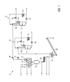
- Fig. 1 the module 1 for the separation of low molecular weight compounds from the contaminated material is shown.
- This module 1 comprises a dryer 2, which can be heated directly or indirectly, with a solids inlet 3, a solids outlet 4 and an outlet 5 for the vapors emerging in the dryer 2.
- the indirect heating of the dryer 2 can be done, for example, by passing hot thermal oil through a heating mantle 6. But it would also be a direct heating, for example via a burner conceivable.
- These heating devices are also components of the module 1.
- a vapor filter 7 is mounted, which prevents the solid particles are introduced into the condenser units 8, 9 with the vapors.
- the capacitor units 8, 9 are constructed almost identical.
- a jet scrubber 10 the vapors are cooled and at least partially condense.
- a condensate collecting tank 11 the condensate is separated from the remaining gas phase.
- the condensate is fed to the wastewater or a pollutant collection container.
- Part of the condensate is cooled by a heat exchanger 13 and returned to the jet scrubber 10 to cool the vapors and cause them to condense.
- the exhaust air from the condensate collection tank 11 is discharged via a demister 14 and a blower 15 and used as a secondary combustion air for the burner for heating the dryer 2. If necessary, the Exhaust air cleaned in front of the burner via an activated charcoal unit.
- the demister 14 prevents liquid droplets are entrained by the exhaust air.
- a vacuum pump 16 is arranged instead of the blower 15. Via the valves 17 and 18 can be adjusted whether the vapors are discharged into the condenser unit 8 or the condenser unit 9. If the dryer 2 is connected to the condenser unit 9, a vacuum is generated in the dryer 2 via the vacuum pump 16. In this way it is possible to remove even compounds with a high boiling point from the material in the dryer.
- an intermediate bunker 19 is arranged. Behind the intermediate bunker 19 is a cooling screw 20 and a remoistening mixer 21. Following the remoistening mixer 21, a conveyor belt 22 is arranged.
- contaminated material is conveyed into the directly or indirectly heated dryer 2.
- the contaminated material is heated to a first temperature.
- This first temperature is in the range of 100 ° C to 150 ° C and is preferably 130 ° C.
- the contaminated material contained compounds having a boiling point lower than 130 ° C evaporate and are withdrawn as vapors via the vapor filter 7 in the condenser unit 8.
- the valve 17 is thus opened, the valve 18 is closed.
- the vapors are fed into the jet scrubber 10 and cooled with already condensed vapors and brought to condensation.
- the liquid In the condensate collection tank 11, the liquid is separated from the remaining gaseous phase, the still warm gaseous phase is removed via the demister 14 and the blower 15 and used as a secondary combustion air for the burner for heating the dryer 2.
- the condensate is fed via a pump 12 to the wastewater or a pollutant reservoir. A portion of the condensate is diverted, cooled in a heat exchanger 13 and fed back into the jet scrubber.
- the valve 17 is closed and the valve 18 is opened.
- the resulting in the dryer 2 vapors are now discharged into the condenser unit 9.
- the temperature in the dryer 2 is increased, to a product temperature of about 300 ° C.
- Via the vacuum pump 16 a vacuum is generated in the dryer 2.
- the treatment of the vapors produced in this step takes place analogously to the preparation in the first step.
- the vapors are passed through the vapor filter 7 in the condenser unit 9. In the jet scrubber 10, the vapors are cooled and condense.
- the condensate In the condensate collecting tank 11, the condensate is separated from the remaining exhaust air.
- the exhaust air is discharged via the demister 14 and the vacuum pump 16 and used as a secondary combustion air for the burner for heating the dryer 2.
- the exhaust air is purified in front of the burner via an activated carbon unit.
- a portion of the condensate is returned via a heat exchanger 13 in the jet scrubber 10 and used there to condense the incoming from the dryer 2 vapors.
- the remainder of the condensate is fed via the pump 12 to the wastewater or a pollutant reservoir.
- the solids outlet 4 of the dryer 2 is opened and the dried and cleaned solid is transferred into the intermediate bunker 19.
- the drying process in module 1 is therefore discontinuous.
- the solid is conveyed into the cooling screw 20 and cooled there to temperatures in the range of 30 ° C to 60 ° C.
- the solid is transferred to the remoistening mixer 21 where it is mixed with a specified amount of water so that the desired moisture of the material is achieved.
- the cleaned and remoistened solid is removed.
- the cooling screw 20 and the remoistening mixer 21 merely have a conveying function.
- Fig. 2 shows a plant for the purification of contaminated soils, consisting of the module 1 for the separation of low molecular weight compounds and the module 23 for the separation of higher molecular weight compounds. If necessary, this module 23 is inserted behind the intermediate bunker 19 and the screw 20. The material is not cooled in the screw 20 in this case, but only promoted.
- the module 23 comprises another directly or indirectly heated dryer 24, such as a rotary tube.
- the module 23 can be operated continuously.
- the dryer 24 can be heated, for example, via a burner 25. It is also an indirect heating of the dryer 24, for example via a heating jacket conceivable.
- the means for heating the dryer 24 are also part of the module 23.
- the dryer 24 in turn has a solids inlet 26, a solids outlet 27 and an exhaust outlet 28 from.
- a combustion chamber 29 with a corresponding burner 30 is arranged.
- the combustion chamber 29 is followed by a waste heat utilization 31 and a quench 32.
- a flue gas cleaner 33 and a blower 34 the exhaust air is discharged through a chimney 35.
- the dried or pre-cleaned material in module 1 is transferred to the intermediate bunker 19 and from there to another dryer 24.
- the desired temperature is set in the dryer 24, preferably, the drying temperature is in the range of 400 ° C to 800 ° C.
- the dryer shown is thus heated directly. But it would also be an indirect heating of the dryer 24 possible.
- a suction draft is set in the module 23, so that the exhaust air from the dryer 24 is drawn into the combustion chamber 25. In the combustion chamber 25 contained in the exhaust organic compounds are burned. Subsequently, the exhaust air is supplied to the waste heat boiler 31, so that the heat generated during drying and combustion can be used further.
- the exhaust air is transferred into the quench 32 and there cooled in a flash by injecting liquid.
- an at least single-stage condenser for separating higher molecular weight compounds from the exhaust air may also be used.
- a flue gas cleaning 33 ensures that in the exhaust air, which is discharged through the chimney 35, no more relevant amounts of pollutants are included.
- the exhaust air is also treated in a flue gas cleaning 33, a portion of the exhaust air used as a secondary combustion air for the burner to heat the dryer 24, the rest of the exhaust air through the chimney 35 dissipated.
- a viscous or solid phase produced in the condenser is fed to external recycling. If a liquid or aqueous phase also arises in the condenser, this can be processed in the module 36. If necessary, the cleaned and dried material is cooled in the cooling screw 39, adjusted to the desired moisture content via the remoistening mixer 21 and transported away via the conveyor belt 22. If the material is not cooled and remoistened, the cooling screw 39 and the remoistening mixer 21 only have a transport function.
- the modules 1, 23 can also be used for drying moist materials.
- Fig. 3 a plant for the treatment of contaminated material with the module 36 for the separation of heavy metals is shown.
- This module 36 connects to the condensate outlet 37 of the module 23 and comprises a precipitation and Schlammabscheide investigatinger 38th
- the following purification method is used.
- the coming out of the dryer 24 exhaust air is post-combusted in the combustion chamber 29, the resulting heat is used via a waste heat boiler 31 and the still warm exhaust air cooled in a quenze 32 like a shock.
- the exhaust air from the dryer 24 is treated in an at least one-stage condenser.
- the condensate or the aqueous / liquid phase arising in the quench 32 or alternatively usable condenser is transferred via the condensate outlet 37 into the precipitation and sludge separation tank 38.
- a suitable precipitant is added to the condensate.
- trimercaptotriazine can be used for this purpose.
- the mercury contained in the condensate combines with the precipitant and precipitates.
- the resulting sludge phase is separated from the remaining liquid and fed to a pollutant reservoir.
- the remaining liquid is fed to the wastewater.
- dry adsorption can also be used.
Priority Applications (1)
| Application Number | Priority Date | Filing Date | Title |
|---|---|---|---|
| EP05024695A EP1785202A1 (fr) | 2005-11-11 | 2005-11-11 | Dispositif et procédé pour nettoyer des matières contaminées |
Applications Claiming Priority (1)
| Application Number | Priority Date | Filing Date | Title |
|---|---|---|---|
| EP05024695A EP1785202A1 (fr) | 2005-11-11 | 2005-11-11 | Dispositif et procédé pour nettoyer des matières contaminées |
Publications (1)
| Publication Number | Publication Date |
|---|---|
| EP1785202A1 true EP1785202A1 (fr) | 2007-05-16 |
Family
ID=36062471
Family Applications (1)
| Application Number | Title | Priority Date | Filing Date |
|---|---|---|---|
| EP05024695A Withdrawn EP1785202A1 (fr) | 2005-11-11 | 2005-11-11 | Dispositif et procédé pour nettoyer des matières contaminées |
Country Status (1)
| Country | Link |
|---|---|
| EP (1) | EP1785202A1 (fr) |
Cited By (10)
| Publication number | Priority date | Publication date | Assignee | Title |
|---|---|---|---|---|
| EP2264368A2 (fr) | 2009-06-18 | 2010-12-22 | EISENMANN Anlagenbau GmbH & Co. KG | Procédé et installation de préparation de matériaux fragmentés pour routes |
| DE102010017075A1 (de) * | 2010-05-25 | 2011-12-01 | Sascha Schröder | Verfahren zur Dekontamination von mit verdampfbaren metallischen und/oder verdampfbaren kohlenstoffhaltigen organischen Schadstoffen belasteten Erdreich |
| WO2013075681A1 (fr) * | 2011-11-25 | 2013-05-30 | Topf, Ulrike | Procédé pour décontaminer un sol renfermant des substances nocives organiques métalliques évaporables et/ou carbonées évaporables |
| WO2013166571A1 (fr) * | 2012-05-07 | 2013-11-14 | Carvalho Jorge Cortizo | Procédé d'obtention de biomasse au moyen d'un traitement de résidus organiques par séchage en deux étapes |
| DE102012016882A1 (de) * | 2012-08-24 | 2014-03-27 | Eisenmann Ag | Anlage zur thermischen Aufbereitung von PAK-haltigem Straßenaufbruchmaterial oder von Ölschlämmen |
| WO2020061661A1 (fr) * | 2018-09-25 | 2020-04-02 | Carvalho Jorge Cortizo | Procédé d'obtention de biomasse par traitement de déchets organiques par séchage en deux étapes |
| CN111602561A (zh) * | 2020-06-09 | 2020-09-01 | 农业农村部环境保护科研监测所 | 一种镉污染土壤上间作种植籽粒苋与小麦的方法 |
| DE102019008187A1 (de) * | 2019-11-26 | 2021-05-27 | Grenzebach Bsh Gmbh | Verfahren und Anordnung zur Behandlung von Straßenaufbruchmaterial |
| DE102020002533A1 (de) | 2020-04-27 | 2021-10-28 | Grenzebach Bsh Gmbh | Schachtofen zur Behandlung von Straßenaufbruchmaterial |
| DE102021210662A1 (de) | 2021-09-24 | 2023-03-30 | Benninghoven Zweigniederlassung Der Wirtgen Mineral Technologies Gmbh | Vorrichtung und Verfahren zum Trocknen von Material sowie Asphaltmischanlage mit einer derartigen Vorrichtung |
Citations (9)
| Publication number | Priority date | Publication date | Assignee | Title |
|---|---|---|---|---|
| US4993943A (en) | 1990-03-02 | 1991-02-19 | Norris David P | Apparatus and method for the removal of higher and lower volatility organic contaminants from soil |
| US5300137A (en) | 1992-09-18 | 1994-04-05 | Pittsburgh Mineral And Environmental Technology, Inc. | Method for removing mercury from contaminated soils and industrial wastes and related apparatus |
| EP0624410A1 (fr) | 1993-05-14 | 1994-11-17 | Westinghouse Electric Corporation | Procédé et dispositif pour éliminer des contaminants volatils et semi-volatils, de solides par thermodesorption |
| EP0896838A2 (fr) | 1997-08-14 | 1999-02-17 | Alexander Czetsch | Procédé et dispositif pour nettoyer des matières contaminées |
| DE19801321A1 (de) * | 1998-01-16 | 1999-07-22 | Brz Bodenreinigungszentrum Her | Verfahren zur Dekontaminierung von mit Quecksilber belasteten Feststoffen |
| EP1005920A2 (fr) * | 1996-04-08 | 2000-06-07 | Foster Wheeler Environmental Corporation | Procédé et dispositif pour traiter des flux de traitement provenant d'un systéme de séparation des constituants d'un matériau contaminé |
| EP1027939A1 (fr) | 1999-02-05 | 2000-08-16 | SNAMPROGETTI S.p.A. | Procédé pour enlever des micro-polluants organiques et/ou inorganiques de boues, en particulier de sédiments marins et lagunaires, ou de sols |
| WO2003070393A1 (fr) | 2002-02-20 | 2003-08-28 | Q'max Solutions Inc. | Procede thermique pour traiter des deblais de forage contamines par des hydrocarbures |
| FR2837495A1 (fr) | 2002-03-19 | 2003-09-26 | Traidec Sa | Installation modulable, demontable, transportable, pour le traitement par thermolyse et pour la valorisation energetique des dechets |
-
2005
- 2005-11-11 EP EP05024695A patent/EP1785202A1/fr not_active Withdrawn
Patent Citations (9)
| Publication number | Priority date | Publication date | Assignee | Title |
|---|---|---|---|---|
| US4993943A (en) | 1990-03-02 | 1991-02-19 | Norris David P | Apparatus and method for the removal of higher and lower volatility organic contaminants from soil |
| US5300137A (en) | 1992-09-18 | 1994-04-05 | Pittsburgh Mineral And Environmental Technology, Inc. | Method for removing mercury from contaminated soils and industrial wastes and related apparatus |
| EP0624410A1 (fr) | 1993-05-14 | 1994-11-17 | Westinghouse Electric Corporation | Procédé et dispositif pour éliminer des contaminants volatils et semi-volatils, de solides par thermodesorption |
| EP1005920A2 (fr) * | 1996-04-08 | 2000-06-07 | Foster Wheeler Environmental Corporation | Procédé et dispositif pour traiter des flux de traitement provenant d'un systéme de séparation des constituants d'un matériau contaminé |
| EP0896838A2 (fr) | 1997-08-14 | 1999-02-17 | Alexander Czetsch | Procédé et dispositif pour nettoyer des matières contaminées |
| DE19801321A1 (de) * | 1998-01-16 | 1999-07-22 | Brz Bodenreinigungszentrum Her | Verfahren zur Dekontaminierung von mit Quecksilber belasteten Feststoffen |
| EP1027939A1 (fr) | 1999-02-05 | 2000-08-16 | SNAMPROGETTI S.p.A. | Procédé pour enlever des micro-polluants organiques et/ou inorganiques de boues, en particulier de sédiments marins et lagunaires, ou de sols |
| WO2003070393A1 (fr) | 2002-02-20 | 2003-08-28 | Q'max Solutions Inc. | Procede thermique pour traiter des deblais de forage contamines par des hydrocarbures |
| FR2837495A1 (fr) | 2002-03-19 | 2003-09-26 | Traidec Sa | Installation modulable, demontable, transportable, pour le traitement par thermolyse et pour la valorisation energetique des dechets |
Cited By (15)
| Publication number | Priority date | Publication date | Assignee | Title |
|---|---|---|---|---|
| EP2264368A2 (fr) | 2009-06-18 | 2010-12-22 | EISENMANN Anlagenbau GmbH & Co. KG | Procédé et installation de préparation de matériaux fragmentés pour routes |
| DE102009025361A1 (de) | 2009-06-18 | 2011-01-05 | Eisenmann Anlagenbau Gmbh & Co. Kg | Verfahren und Anlage zur Aufbereitung von Straßenaufbruchmaterial |
| DE102009025361B4 (de) * | 2009-06-18 | 2012-03-01 | Eisenmann Ag | Verfahren und Anlage zur Aufbereitung von Straßenaufbruchmaterial |
| DE102010017075A1 (de) * | 2010-05-25 | 2011-12-01 | Sascha Schröder | Verfahren zur Dekontamination von mit verdampfbaren metallischen und/oder verdampfbaren kohlenstoffhaltigen organischen Schadstoffen belasteten Erdreich |
| DE102010017075B4 (de) * | 2010-05-25 | 2013-02-07 | Sascha Schröder | Verfahren zur Dekontamination von mit verdampfbaren metallischen und/oder verdampfbaren kohlenstoffhaltigen organischen Schadstoffen belasteten Erdreich |
| WO2013075681A1 (fr) * | 2011-11-25 | 2013-05-30 | Topf, Ulrike | Procédé pour décontaminer un sol renfermant des substances nocives organiques métalliques évaporables et/ou carbonées évaporables |
| WO2013166571A1 (fr) * | 2012-05-07 | 2013-11-14 | Carvalho Jorge Cortizo | Procédé d'obtention de biomasse au moyen d'un traitement de résidus organiques par séchage en deux étapes |
| DE102012016882A1 (de) * | 2012-08-24 | 2014-03-27 | Eisenmann Ag | Anlage zur thermischen Aufbereitung von PAK-haltigem Straßenaufbruchmaterial oder von Ölschlämmen |
| DE102012016882B4 (de) * | 2012-08-24 | 2014-07-03 | Eisenmann Ag | Verfahren zum Betreiben einer Anlage zur thermischen Aufbereitung von PAK-haltigem Straßenaufbruchmaterial oder von Ölschlämmen |
| WO2020061661A1 (fr) * | 2018-09-25 | 2020-04-02 | Carvalho Jorge Cortizo | Procédé d'obtention de biomasse par traitement de déchets organiques par séchage en deux étapes |
| DE102019008187A1 (de) * | 2019-11-26 | 2021-05-27 | Grenzebach Bsh Gmbh | Verfahren und Anordnung zur Behandlung von Straßenaufbruchmaterial |
| WO2021104661A1 (fr) | 2019-11-26 | 2021-06-03 | Grenzebach Bsh Gmbh | Procédé et ensemble pour traiter un mélange de matière solides minérales |
| DE102020002533A1 (de) | 2020-04-27 | 2021-10-28 | Grenzebach Bsh Gmbh | Schachtofen zur Behandlung von Straßenaufbruchmaterial |
| CN111602561A (zh) * | 2020-06-09 | 2020-09-01 | 农业农村部环境保护科研监测所 | 一种镉污染土壤上间作种植籽粒苋与小麦的方法 |
| DE102021210662A1 (de) | 2021-09-24 | 2023-03-30 | Benninghoven Zweigniederlassung Der Wirtgen Mineral Technologies Gmbh | Vorrichtung und Verfahren zum Trocknen von Material sowie Asphaltmischanlage mit einer derartigen Vorrichtung |
Similar Documents
| Publication | Publication Date | Title |
|---|---|---|
| EP1785202A1 (fr) | Dispositif et procédé pour nettoyer des matières contaminées | |
| EP0343431B1 (fr) | Procédé et dispositif pour sécher des bones d'eaux d'égout | |
| DE2753537C2 (de) | Verfahren zur thermischen Behandlung von wäßrigen Schlämmen, insbesondere von Klärschlämmen \ | |
| EP1363855B1 (fr) | Procede et dispositif de traitement de liquides | |
| DE4120277A1 (de) | Verfahren und vorrichtung zum reinigen von abgasen aus ofenanlagen | |
| DE2422814A1 (de) | Verfahren und anlage zum reinigen von verunreinigten fluessigkeiten | |
| DE2726302A1 (de) | Verfahren und anlage zur reinigung von abwaessern | |
| EP0716264B1 (fr) | Procédé et installation pour la combustion des boues | |
| EP0254024B1 (fr) | Procédé et installation pour convertir le tourteau de filtrage de boues d'épuration en l'huile, gaz et coke par pyrolyse | |
| CN203018449U (zh) | 一种污染土壤的热处理修复设备 | |
| EP0883778B1 (fr) | Procede d'incineration de boues d'epuration et installation correspondante | |
| EP0701491B1 (fr) | Procede et dispositif pour le nettoyage de terres polluees | |
| EP0094547B1 (fr) | Installation pour éliminer les eaux d'infiltration et les gaz de décomposition dans les dépôts d'ordures | |
| EP0176963A2 (fr) | Procédé et dispositif pour la séparation de la charge de composition complexe à partir de déchets liquides comme eaux résiduaires industrielles et eaux de drainage de décharges contrôlées | |
| EP0692679A2 (fr) | Procédé et schéma d'installation pour le séchage et l'incinération de boues d'égout | |
| DE4217729A1 (de) | Verfahren und anlagentechnische Schaltung zur Trocknung und Verbrennung von Abfallstoffen | |
| DE3734281A1 (de) | Verfahren zum entwaessern von wasserhaltigen und insbesondere von kontaminierten wasserhaltigen schlamm- und feststoffaggregaten und hierzu geeignete vorrichtung | |
| EP0896838A2 (fr) | Procédé et dispositif pour nettoyer des matières contaminées | |
| EP1378494B1 (fr) | Procédé et installation pour traiter des résidus d'origine biologique, en particulier des boues | |
| DE2535683A1 (de) | Verfahren und vorrichtung zur verbrennung von schlaemmen mit hilfe rekuperativer schlammtrocknung | |
| WO1991002702A1 (fr) | Procede de sechage et/ou d'incineration de boues de decantation | |
| WO1993015816A1 (fr) | Procede visant a une meilleure elimination des buees dans le sechage par vapeur chaude | |
| DE19702430C2 (de) | Verfahren und Vorrichtung zur Restdampf- und Brauchwasseraufbereitung einer Kalk-Sandstein-Härteanlage | |
| DE19635360A1 (de) | Verfahren zum Verbrennen von feuchten Massen, insbesondere Klärschlamm | |
| DE2128259A1 (de) | Verfahren und Vorrichtung zur Aufbereitung von flussigem Abfall |
Legal Events
| Date | Code | Title | Description |
|---|---|---|---|
| PUAI | Public reference made under article 153(3) epc to a published international application that has entered the european phase |
Free format text: ORIGINAL CODE: 0009012 |
|
| 17P | Request for examination filed |
Effective date: 20060621 |
|
| AK | Designated contracting states |
Kind code of ref document: A1 Designated state(s): AT BE BG CH CY CZ DE DK EE ES FI FR GB GR HU IE IS IT LI LT LU LV MC NL PL PT RO SE SI SK TR |
|
| AX | Request for extension of the european patent |
Extension state: AL BA HR MK YU |
|
| RIN1 | Information on inventor provided before grant (corrected) |
Inventor name: DAUB, ROMAN |
|
| AKX | Designation fees paid |
Designated state(s): AT BE BG CH CY CZ DE DK EE ES FI FR GB GR HU IE IS IT LI LT LU LV MC NL PL PT RO SE SI SK TR |
|
| RIC1 | Information provided on ipc code assigned before grant |
Ipc: F26B 25/00 20060101ALI20110405BHEP Ipc: B09B 3/00 20060101ALI20110405BHEP Ipc: B09C 1/06 20060101AFI20110405BHEP |
|
| GRAP | Despatch of communication of intention to grant a patent |
Free format text: ORIGINAL CODE: EPIDOSNIGR1 |
|
| STAA | Information on the status of an ep patent application or granted ep patent |
Free format text: STATUS: THE APPLICATION IS DEEMED TO BE WITHDRAWN |
|
| 18D | Application deemed to be withdrawn |
Effective date: 20111007 |