EP1785196A1 - Rouleau d'encrage - Google Patents
Rouleau d'encrage Download PDFInfo
- Publication number
- EP1785196A1 EP1785196A1 EP05024917A EP05024917A EP1785196A1 EP 1785196 A1 EP1785196 A1 EP 1785196A1 EP 05024917 A EP05024917 A EP 05024917A EP 05024917 A EP05024917 A EP 05024917A EP 1785196 A1 EP1785196 A1 EP 1785196A1
- Authority
- EP
- European Patent Office
- Prior art keywords
- roller
- fluid
- roller according
- core
- hoses
- Prior art date
- Legal status (The legal status is an assumption and is not a legal conclusion. Google has not performed a legal analysis and makes no representation as to the accuracy of the status listed.)
- Granted
Links
- 239000003973 paint Substances 0.000 claims abstract description 20
- 239000012530 fluid Substances 0.000 claims description 25
- 239000000463 material Substances 0.000 claims description 13
- 239000007788 liquid Substances 0.000 claims description 3
- 230000000087 stabilizing effect Effects 0.000 claims 1
- 239000004922 lacquer Substances 0.000 abstract description 4
- 239000000758 substrate Substances 0.000 description 19
- 239000002023 wood Substances 0.000 description 8
- 238000007639 printing Methods 0.000 description 7
- 238000000034 method Methods 0.000 description 5
- 239000004033 plastic Substances 0.000 description 5
- 239000011148 porous material Substances 0.000 description 4
- 239000002966 varnish Substances 0.000 description 3
- 229920001875 Ebonite Polymers 0.000 description 1
- 230000006978 adaptation Effects 0.000 description 1
- 239000011248 coating agent Substances 0.000 description 1
- 238000000576 coating method Methods 0.000 description 1
- 239000010438 granite Substances 0.000 description 1
- 238000007646 gravure printing Methods 0.000 description 1
- 239000004579 marble Substances 0.000 description 1
- 238000011089 mechanical engineering Methods 0.000 description 1
- 239000002184 metal Substances 0.000 description 1
- 238000002360 preparation method Methods 0.000 description 1
- 238000005096 rolling process Methods 0.000 description 1
- 229920002379 silicone rubber Polymers 0.000 description 1
- 239000004945 silicone rubber Substances 0.000 description 1
- 238000005507 spraying Methods 0.000 description 1
- 239000004575 stone Substances 0.000 description 1
- XLYOFNOQVPJJNP-UHFFFAOYSA-N water Substances O XLYOFNOQVPJJNP-UHFFFAOYSA-N 0.000 description 1
Images
Classifications
-
- B—PERFORMING OPERATIONS; TRANSPORTING
- B05—SPRAYING OR ATOMISING IN GENERAL; APPLYING FLUENT MATERIALS TO SURFACES, IN GENERAL
- B05C—APPARATUS FOR APPLYING FLUENT MATERIALS TO SURFACES, IN GENERAL
- B05C1/00—Apparatus in which liquid or other fluent material is applied to the surface of the work by contact with a member carrying the liquid or other fluent material, e.g. a porous member loaded with a liquid to be applied as a coating
- B05C1/04—Apparatus in which liquid or other fluent material is applied to the surface of the work by contact with a member carrying the liquid or other fluent material, e.g. a porous member loaded with a liquid to be applied as a coating for applying liquid or other fluent material to work of indefinite length
- B05C1/08—Apparatus in which liquid or other fluent material is applied to the surface of the work by contact with a member carrying the liquid or other fluent material, e.g. a porous member loaded with a liquid to be applied as a coating for applying liquid or other fluent material to work of indefinite length using a roller or other rotating member which contacts the work along a generating line
- B05C1/0808—Details thereof, e.g. surface characteristics
-
- B—PERFORMING OPERATIONS; TRANSPORTING
- B05—SPRAYING OR ATOMISING IN GENERAL; APPLYING FLUENT MATERIALS TO SURFACES, IN GENERAL
- B05C—APPARATUS FOR APPLYING FLUENT MATERIALS TO SURFACES, IN GENERAL
- B05C1/00—Apparatus in which liquid or other fluent material is applied to the surface of the work by contact with a member carrying the liquid or other fluent material, e.g. a porous member loaded with a liquid to be applied as a coating
- B05C1/02—Apparatus in which liquid or other fluent material is applied to the surface of the work by contact with a member carrying the liquid or other fluent material, e.g. a porous member loaded with a liquid to be applied as a coating for applying liquid or other fluent material to separate articles
-
- B—PERFORMING OPERATIONS; TRANSPORTING
- B05—SPRAYING OR ATOMISING IN GENERAL; APPLYING FLUENT MATERIALS TO SURFACES, IN GENERAL
- B05C—APPARATUS FOR APPLYING FLUENT MATERIALS TO SURFACES, IN GENERAL
- B05C1/00—Apparatus in which liquid or other fluent material is applied to the surface of the work by contact with a member carrying the liquid or other fluent material, e.g. a porous member loaded with a liquid to be applied as a coating
- B05C1/04—Apparatus in which liquid or other fluent material is applied to the surface of the work by contact with a member carrying the liquid or other fluent material, e.g. a porous member loaded with a liquid to be applied as a coating for applying liquid or other fluent material to work of indefinite length
- B05C1/08—Apparatus in which liquid or other fluent material is applied to the surface of the work by contact with a member carrying the liquid or other fluent material, e.g. a porous member loaded with a liquid to be applied as a coating for applying liquid or other fluent material to work of indefinite length using a roller or other rotating member which contacts the work along a generating line
- B05C1/0813—Apparatus in which liquid or other fluent material is applied to the surface of the work by contact with a member carrying the liquid or other fluent material, e.g. a porous member loaded with a liquid to be applied as a coating for applying liquid or other fluent material to work of indefinite length using a roller or other rotating member which contacts the work along a generating line characterised by means for supplying liquid or other fluent material to the roller
-
- B—PERFORMING OPERATIONS; TRANSPORTING
- B05—SPRAYING OR ATOMISING IN GENERAL; APPLYING FLUENT MATERIALS TO SURFACES, IN GENERAL
- B05C—APPARATUS FOR APPLYING FLUENT MATERIALS TO SURFACES, IN GENERAL
- B05C1/00—Apparatus in which liquid or other fluent material is applied to the surface of the work by contact with a member carrying the liquid or other fluent material, e.g. a porous member loaded with a liquid to be applied as a coating
- B05C1/04—Apparatus in which liquid or other fluent material is applied to the surface of the work by contact with a member carrying the liquid or other fluent material, e.g. a porous member loaded with a liquid to be applied as a coating for applying liquid or other fluent material to work of indefinite length
- B05C1/08—Apparatus in which liquid or other fluent material is applied to the surface of the work by contact with a member carrying the liquid or other fluent material, e.g. a porous member loaded with a liquid to be applied as a coating for applying liquid or other fluent material to work of indefinite length using a roller or other rotating member which contacts the work along a generating line
- B05C1/086—Apparatus in which liquid or other fluent material is applied to the surface of the work by contact with a member carrying the liquid or other fluent material, e.g. a porous member loaded with a liquid to be applied as a coating for applying liquid or other fluent material to work of indefinite length using a roller or other rotating member which contacts the work along a generating line a pool of coating material being formed between a roller, e.g. a dosing roller and an element cooperating therewith
- B05C1/0865—Apparatus in which liquid or other fluent material is applied to the surface of the work by contact with a member carrying the liquid or other fluent material, e.g. a porous member loaded with a liquid to be applied as a coating for applying liquid or other fluent material to work of indefinite length using a roller or other rotating member which contacts the work along a generating line a pool of coating material being formed between a roller, e.g. a dosing roller and an element cooperating therewith the cooperating element being a roller, e.g. a coating roller
Definitions
- the invention relates to a roller for transferring paint and / or paint to an object.
- Articles which are to be printed with the roll according to the invention may for example consist of a wood material or a plastic.
- the roll according to the invention is suitable for printing articles with a profile, i. not just a flat surface should be printed, but a three-dimensional structure.
- the paint and / or the paint should be applied simultaneously to surfaces of the article, which have different distances from the surface of the roller and in particular are not parallel, so form bends or corners.
- printing such profiled articles in one operation is a technical problem to which the present invention adopts.
- the invention provides a roller for transferring paint and / or lacquer to an article having a hard roll core and an elastic layer surrounding the roll core with a space in which a fluid is arranged which pressurizes the layer radially outward ,
- the fluid may be a gas, e.g. Air, or a liquid, e.g. Water, oil etc. act.
- said elastic layer is part of a tube surrounding the roller core.
- a further preferred embodiment of the invention provides that the elastic layer is surrounded radially on the outside by a sleeve.
- the material of the shell preferably has a greater hardness than the material of the elastic layer.
- paint and / or varnish can be applied homogeneously and with high quality to, in particular, articles which are characterized by a more or less complicated profiling, such as window frames, door frames, furniture parts, plastic panels, parts of automotive fittings, plastic housing of all kinds, such as housing for mobile phones, etc.
- this adaptation takes place in that the pressure in the fluid can be changed depending on the profile of the object to be printed.
- the material of the outer shell can be chosen so that it has optimal properties for receiving and dispensing paint and / or paint.
- the mechanical properties are more relevant the materials of the elastic layer, so according to the preferred embodiment of the hose, which is not involved even in the process of receiving and dispensing of paint and / or paint, so far as the choice of materials is not limited.
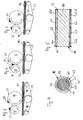
- a substrate 10 is conveyed from left to right.
- the substrate 10 is, for example, a board of wood-based material or a plastic board of e.g. ABS or PVC.
- the substrate 10 may be an article having a more or less complicated three-dimensional profile, such as a part of a window frame or the like. In the figures, the profile is not shown in detail for the sake of simplicity.
- the promotion of the substrate 10 is carried out with a conveyor belt 12 which is driven by rollers 14.
- the direction of transport corresponds to that indicated by the direction of rotation indicated by the arrows.
- a basecoat which for example can be slightly colored, can be applied to the substrate in the transport path of the substrate (ie to the left of FIG. 1), in particular by spraying or rolling or the like.
- a base coat is also a metallic paint into consideration. This preparation the substrate before its promotion in the first order station according to Figure 1 is not shown in the figures.
- the application station according to FIG. 1 has a gravure printing roller 16, which is shown in section, for example, in FIGS. 4 and 5.
- the pressure roller 16 has a surface 20.
- the pressure roller 16 cooperates with a gravure cylinder 18.
- Recesses are formed in the surface of the engraving cylinder 18, which correspond to the printed image to be produced on the substrate 10, that is to say recesses corresponding to a natural wood grain or also corresponding to a natural stone image, such as marble or granite.
- the directions of rotation of the engraving cylinder 18 and the pressure roller 16 are indicated by arrows.
- doctoring devices 22, 24 keep the surfaces of the cylinder or the roller clean, so that the ink appears only at the desired locations.
- the substrate 10 moves in the direction of rotation of the pressure roller 16 with this in abutment, so that the printed image is transferred from the surface 20 of the pressure roller 16 to the substrate 10.
- a second application station In the transport of the substrate 10 is a second application station according to Figure 2 with a paint applicator roll 26 and a paint metering roller 28.
- a paint 32 is applied to the printed surface 30 of the substrate 10.
- the directions of rotation of the rollers are again indicated by arrows.
- the rollers will turn of doctor devices 34, 36 acted upon. Details of the roller 26 are described below with reference to Figures 4 and 5 in more detail.
- the substrate 10 printed in the first application station according to FIG. 1 and painted in the second application station according to FIG. 2 is conveyed by the conveyor belt 36 to a third application station according to FIG. There, a further lacquer layer is applied to the printed and lacquered surface 40 of the substrate 10 by means of a conveyor belt 42, which is driven by rollers 44, and a pore pressure roller 46, which cooperates with a gravure cylinder 48.
- a conveyor belt 42 which is driven by rollers 44, and a pore pressure roller 46, which cooperates with a gravure cylinder 48.
- the directions of rotation of the rotating components are again marked with arrows. Details of the roller 26 are described below with reference to Figures 4 and 5 in more detail.
- a gravure cylinder 48 which carries projections which correspond to the pores ultimately to be printed on the substrate 10.
- the pore-pressure roller 46 is provided with a lacquer layer intentionally has small holes ("missing dots"), whose distribution corresponds exactly to the desired pore image of the reproduced wood surface. Doctor devices 50, 52 cooperate with the rollers.
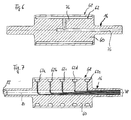
- FIGS. 4 and 5 schematically show exemplary embodiments of the pressure rollers 16, 26, 46 used above.
- the roller 16 has a hard roller core 60 of, for example, metal, which is rotatable in a conventional manner about an axis of rotation.
- FIG. 4 shows a radial section and FIG. 5 shows an axial section through the roller 16.
- Each hose 62 has an inner hose wall 64 and an outer hose wall 66.
- the inner hose wall 64 abuts the surface 70 of the roll core 60.
- the outer hose wall 66 is important for the printing process. It supports radially inside an outer shell 68, which causes the printing process.
- the sheath 68 extends across the entire width of the roller 16 between two end flanges 72, 74 which position both the hoses and the sheath.
- a fluid for example a gas or a liquid
- each of the hoses 62a, 62b, 62c, 62d may be selectively actuated via valves (not shown), and thus the pressure in each of the hoses may be adjusted individually, independently of the other hoses, such that the pressure with which the respective one of the hoses 62a, 62b, 62c, 62d
- Hose sleeve 68 is supported, can be adapted to the respective profile of the object to be printed.
- the shell 68 can specifically adapt to the profile of the object.
- the outer shell 68 a material of greater hardness is chosen than for the tube 62.
- the material of the outer shell 68 has a hardness greater than 40 Shore.
- An advantage of the rollers described is that the outer shell 68 is easily replaceable when worn.
- a softer material is chosen as the sheath 68, for example a silicone rubber having a thickness of 1 to 3 mm.
- a hard rubber is suitable for the outer shell 68.
- the embodiment described above may, in a simpler embodiment, be modified such that all hoses 62a, 62b, 62c, 62d are conductively connected so that the fluid pressure in them is equal.
- the means (valves, lines) to adjust the pressure in the hoses are not shown in detail in FIG.
- the conduits may pass through the roller core 60 and from there to the individual hoses.
- the conduits may also extend in the space between the outer surface 70 of the roller core 60 and the sheath 68.
- FIGS. 6 and 7 show exemplary embodiments of how a hose or several tubes can be supplied with fluid.
- a single tube 62 is provided, which is supplied with fluid via a fluid line 76 which is formed in the roller core 60. Via a rotary seal, the fluid supply can also be carried out during operation, so that in particular the fluid pressure can be permanently monitored.
- Figure 7 shows an embodiment with five hoses 62a, 62b, ...., 62e, which can be pressurized via fluid lines 78 either with fluid pressure, so that in each hose individually either a desired pressure is adjustable.
- the fluid lines can be connected via a rotary seal in each case with a central fluid supply.
- the lines run in an axial cavity 80 of the roller core 60, which is sealed by a plug 82.
- the fluid lines 78 can be provided with the desired fluid pressure before the beginning of the printing process at standstill of the roller, whereupon then the lines are closed and the roller takes up the operation. No rotary seals are required. However, if the fluid pressure during operation is continuously monitored and adjusted if necessary, rotary seals for the leads 78 are required, which are known as such in mechanical engineering (hydraulics).
- rollers described can be used not only in a printing arrangement according to Figures 1 to 3, but in general when transferring paint and / or paint on an object.
Landscapes
- Coating Apparatus (AREA)
- Rolls And Other Rotary Bodies (AREA)
- Inking, Control Or Cleaning Of Printing Machines (AREA)
Priority Applications (3)
| Application Number | Priority Date | Filing Date | Title |
|---|---|---|---|
| AT05024917T ATE401972T1 (de) | 2005-11-15 | 2005-11-15 | Farbauftragswalze |
| EP05024917A EP1785196B1 (fr) | 2005-11-15 | 2005-11-15 | Rouleau d'encrage |
| DE502005004828T DE502005004828D1 (de) | 2005-11-15 | 2005-11-15 | Farbauftragswalze |
Applications Claiming Priority (1)
| Application Number | Priority Date | Filing Date | Title |
|---|---|---|---|
| EP05024917A EP1785196B1 (fr) | 2005-11-15 | 2005-11-15 | Rouleau d'encrage |
Publications (2)
| Publication Number | Publication Date |
|---|---|
| EP1785196A1 true EP1785196A1 (fr) | 2007-05-16 |
| EP1785196B1 EP1785196B1 (fr) | 2008-07-23 |
Family
ID=36378790
Family Applications (1)
| Application Number | Title | Priority Date | Filing Date |
|---|---|---|---|
| EP05024917A Ceased EP1785196B1 (fr) | 2005-11-15 | 2005-11-15 | Rouleau d'encrage |
Country Status (3)
| Country | Link |
|---|---|
| EP (1) | EP1785196B1 (fr) |
| AT (1) | ATE401972T1 (fr) |
| DE (1) | DE502005004828D1 (fr) |
Cited By (2)
| Publication number | Priority date | Publication date | Assignee | Title |
|---|---|---|---|---|
| WO2010028857A1 (fr) * | 2008-09-12 | 2010-03-18 | Demaxz Ag | Procédé pour appliquer sur des profilés une couche décorative adhérant de manière amovible à un film support, et structure de film associée |
| WO2010063315A1 (fr) * | 2008-12-03 | 2010-06-10 | Spanolux N.V.- Div. Balterio | Appareil permettant de revêtir une partie bord d'un panneau |
Citations (1)
| Publication number | Priority date | Publication date | Assignee | Title |
|---|---|---|---|---|
| US5875514A (en) * | 1995-10-19 | 1999-03-02 | Friess Gmbh | Padded basket roller |
-
2005
- 2005-11-15 EP EP05024917A patent/EP1785196B1/fr not_active Ceased
- 2005-11-15 DE DE502005004828T patent/DE502005004828D1/de not_active Expired - Fee Related
- 2005-11-15 AT AT05024917T patent/ATE401972T1/de not_active IP Right Cessation
Patent Citations (1)
| Publication number | Priority date | Publication date | Assignee | Title |
|---|---|---|---|---|
| US5875514A (en) * | 1995-10-19 | 1999-03-02 | Friess Gmbh | Padded basket roller |
Cited By (2)
| Publication number | Priority date | Publication date | Assignee | Title |
|---|---|---|---|---|
| WO2010028857A1 (fr) * | 2008-09-12 | 2010-03-18 | Demaxz Ag | Procédé pour appliquer sur des profilés une couche décorative adhérant de manière amovible à un film support, et structure de film associée |
| WO2010063315A1 (fr) * | 2008-12-03 | 2010-06-10 | Spanolux N.V.- Div. Balterio | Appareil permettant de revêtir une partie bord d'un panneau |
Also Published As
| Publication number | Publication date |
|---|---|
| EP1785196B1 (fr) | 2008-07-23 |
| ATE401972T1 (de) | 2008-08-15 |
| DE502005004828D1 (de) | 2008-09-04 |
Similar Documents
| Publication | Publication Date | Title |
|---|---|---|
| DE69308896T2 (de) | Farbkasten | |
| EP2632605B1 (fr) | Appareil pour appliquer un liquide à une bande | |
| DE102005006084B4 (de) | Verfahren und Vorrichtung zum Erzeugen einer strukturierten Lackoberfläche sowie Paneel mit einer strukturierten Lackoberfläche | |
| EP3090882B1 (fr) | Piece en forme de plaque comprenant une surface ayant des differentes de brillance et procede de production d'une telle surface | |
| EP0619186A1 (fr) | Dispositif de revêtement dans des machines d'impression | |
| DE102012103491A1 (de) | Verfahren und Vorrichtung zur Herstellung einer strukturierten Lackoberfläche | |
| DE10225541A1 (de) | Verfahren und Vorrichtung zum Herstellen eines hülsenförmigen Gummituchs | |
| EP1785196B1 (fr) | Rouleau d'encrage | |
| WO1987001308A1 (fr) | Dispositif d'application et de dosage d'agents fluides sur une bande ou sur un cylindre | |
| EP0906788A2 (fr) | Dispositif de râclage pour un appareil d'application de produits fluides à pâteux sur un substrat défilant | |
| EP1115950B1 (fr) | Racle en forme de tige destinee a un dispositif de recouvrement | |
| DE2754663A1 (de) | Vorrichtung zum auftragen von medien in ein substrat | |
| EP0659557A1 (fr) | Dispositif de dosage d'un moyen liquide dans une machine d'impression offset en particulier un dispositif de laquage | |
| DE4421310C2 (de) | Beschichtungs- oder Farbauftragwalze | |
| DE29716541U1 (de) | Vorrichtung zum Auftragen von Flüssigkeiten auf ein Substrat | |
| WO2007131753A1 (fr) | Dispositif et procédé d'impression d'un substrat sans fin avec un décor | |
| DE102004037892B3 (de) | Vorrichtung und Auftragswalze sowie Verfahren zum Aufbringen eines Mediums, insbesondere einer Flüssigkeit, auf Artikel | |
| EP0828612B1 (fr) | Systeme d'encrage pour machines d'impression | |
| DE102004015334B3 (de) | Rasterwalzen und Verfahren zu deren Herstellung | |
| DE202015104113U1 (de) | Beschichtungsvorrichtung zum Auftrag eines flüssigen Beschichtungsmittels auf ein langgestrecktes Werkstück | |
| DE20320598U1 (de) | Dosiereinrichtung für Farben und Lacke | |
| EP1957276B1 (fr) | Dispositif et procede pour imprimer des bouchons de bouteille cylindriques | |
| DE202004020383U1 (de) | Vorrichtung zum Aufbringen eines Mediums, insbesondere einer Flüssigkeit, auf Artikel | |
| DE102024109856A1 (de) | Vorrichtung zum Auftragen eines Beschichtungsmittels | |
| DE102006030057A1 (de) | Farbwerk einer Rotationsdruckmaschine |
Legal Events
| Date | Code | Title | Description |
|---|---|---|---|
| PUAI | Public reference made under article 153(3) epc to a published international application that has entered the european phase |
Free format text: ORIGINAL CODE: 0009012 |
|
| AK | Designated contracting states |
Kind code of ref document: A1 Designated state(s): AT BE BG CH CY CZ DE DK EE ES FI FR GB GR HU IE IS IT LI LT LU LV MC NL PL PT RO SE SI SK TR |
|
| AX | Request for extension of the european patent |
Extension state: AL BA HR MK YU |
|
| 17P | Request for examination filed |
Effective date: 20071107 |
|
| AKX | Designation fees paid |
Designated state(s): AT CH DE IT LI |
|
| GRAP | Despatch of communication of intention to grant a patent |
Free format text: ORIGINAL CODE: EPIDOSNIGR1 |
|
| GRAS | Grant fee paid |
Free format text: ORIGINAL CODE: EPIDOSNIGR3 |
|
| GRAA | (expected) grant |
Free format text: ORIGINAL CODE: 0009210 |
|
| AK | Designated contracting states |
Kind code of ref document: B1 Designated state(s): AT CH DE IT LI |
|
| REG | Reference to a national code |
Ref country code: CH Ref legal event code: EP |
|
| REF | Corresponds to: |
Ref document number: 502005004828 Country of ref document: DE Date of ref document: 20080904 Kind code of ref document: P |
|
| PGFP | Annual fee paid to national office [announced via postgrant information from national office to epo] |
Ref country code: DE Payment date: 20081126 Year of fee payment: 4 |
|
| PGFP | Annual fee paid to national office [announced via postgrant information from national office to epo] |
Ref country code: AT Payment date: 20080917 Year of fee payment: 4 |
|
| PLBE | No opposition filed within time limit |
Free format text: ORIGINAL CODE: 0009261 |
|
| STAA | Information on the status of an ep patent application or granted ep patent |
Free format text: STATUS: NO OPPOSITION FILED WITHIN TIME LIMIT |
|
| 26N | No opposition filed |
Effective date: 20090424 |
|
| PGFP | Annual fee paid to national office [announced via postgrant information from national office to epo] |
Ref country code: IT Payment date: 20081130 Year of fee payment: 4 |
|
| PGFP | Annual fee paid to national office [announced via postgrant information from national office to epo] |
Ref country code: CH Payment date: 20091020 Year of fee payment: 5 |
|
| PG25 | Lapsed in a contracting state [announced via postgrant information from national office to epo] |
Ref country code: AT Free format text: LAPSE BECAUSE OF NON-PAYMENT OF DUE FEES Effective date: 20091115 |
|
| PG25 | Lapsed in a contracting state [announced via postgrant information from national office to epo] |
Ref country code: DE Free format text: LAPSE BECAUSE OF NON-PAYMENT OF DUE FEES Effective date: 20100601 |
|
| PG25 | Lapsed in a contracting state [announced via postgrant information from national office to epo] |
Ref country code: IT Free format text: LAPSE BECAUSE OF NON-PAYMENT OF DUE FEES Effective date: 20091115 |
|
| REG | Reference to a national code |
Ref country code: CH Ref legal event code: PL |
|
| PG25 | Lapsed in a contracting state [announced via postgrant information from national office to epo] |
Ref country code: LI Free format text: LAPSE BECAUSE OF NON-PAYMENT OF DUE FEES Effective date: 20101130 Ref country code: CH Free format text: LAPSE BECAUSE OF NON-PAYMENT OF DUE FEES Effective date: 20101130 |