EP1782721B1 - Duschtassenelement mit einer Ablaufrinne - Google Patents
Duschtassenelement mit einer Ablaufrinne Download PDFInfo
- Publication number
- EP1782721B1 EP1782721B1 EP06123363.1A EP06123363A EP1782721B1 EP 1782721 B1 EP1782721 B1 EP 1782721B1 EP 06123363 A EP06123363 A EP 06123363A EP 1782721 B1 EP1782721 B1 EP 1782721B1
- Authority
- EP
- European Patent Office
- Prior art keywords
- shower
- frame
- channel
- element according
- shower tray
- Prior art date
- Legal status (The legal status is an assumption and is not a legal conclusion. Google has not performed a legal analysis and makes no representation as to the accuracy of the status listed.)
- Active
Links
Images


Classifications
-
- A—HUMAN NECESSITIES
- A47—FURNITURE; DOMESTIC ARTICLES OR APPLIANCES; COFFEE MILLS; SPICE MILLS; SUCTION CLEANERS IN GENERAL
- A47K—SANITARY EQUIPMENT; ACCESSORIES THEREFOR, e.g. TOILET ACCESSORIES
- A47K3/00—Baths; Showers; Appurtenances therefor
- A47K3/16—Devices for fastening baths to floors or walls; Adjustable bath feet ; Lining panels or attachments therefor
- A47K3/1605—Hard foam bathtub supports
-
- A—HUMAN NECESSITIES
- A47—FURNITURE; DOMESTIC ARTICLES OR APPLIANCES; COFFEE MILLS; SPICE MILLS; SUCTION CLEANERS IN GENERAL
- A47K—SANITARY EQUIPMENT; ACCESSORIES THEREFOR, e.g. TOILET ACCESSORIES
- A47K3/00—Baths; Showers; Appurtenances therefor
- A47K3/28—Showers or bathing douches
- A47K3/40—Pans or trays
-
- E—FIXED CONSTRUCTIONS
- E03—WATER SUPPLY; SEWERAGE
- E03F—SEWERS; CESSPOOLS
- E03F5/00—Sewerage structures
- E03F5/04—Gullies inlets, road sinks, floor drains with or without odour seals or sediment traps
- E03F5/0407—Floor drains for indoor use
- E03F5/0408—Floor drains for indoor use specially adapted for showers
-
- E—FIXED CONSTRUCTIONS
- E03—WATER SUPPLY; SEWERAGE
- E03F—SEWERS; CESSPOOLS
- E03F5/00—Sewerage structures
- E03F5/04—Gullies inlets, road sinks, floor drains with or without odour seals or sediment traps
- E03F2005/0412—Gullies inlets, road sinks, floor drains with or without odour seals or sediment traps with means for adjusting their position with respect to the surrounding surface
- E03F2005/0413—Gullies inlets, road sinks, floor drains with or without odour seals or sediment traps with means for adjusting their position with respect to the surrounding surface for height adjustment
-
- E—FIXED CONSTRUCTIONS
- E03—WATER SUPPLY; SEWERAGE
- E03F—SEWERS; CESSPOOLS
- E03F5/00—Sewerage structures
- E03F5/04—Gullies inlets, road sinks, floor drains with or without odour seals or sediment traps
- E03F2005/0412—Gullies inlets, road sinks, floor drains with or without odour seals or sediment traps with means for adjusting their position with respect to the surrounding surface
- E03F2005/0415—Gullies inlets, road sinks, floor drains with or without odour seals or sediment traps with means for adjusting their position with respect to the surrounding surface for horizontal position adjustment
-
- E—FIXED CONSTRUCTIONS
- E03—WATER SUPPLY; SEWERAGE
- E03F—SEWERS; CESSPOOLS
- E03F5/00—Sewerage structures
- E03F5/04—Gullies inlets, road sinks, floor drains with or without odour seals or sediment traps
- E03F2005/0416—Gullies inlets, road sinks, floor drains with or without odour seals or sediment traps with an odour seal
-
- E—FIXED CONSTRUCTIONS
- E03—WATER SUPPLY; SEWERAGE
- E03F—SEWERS; CESSPOOLS
- E03F5/00—Sewerage structures
- E03F5/04—Gullies inlets, road sinks, floor drains with or without odour seals or sediment traps
- E03F2005/0416—Gullies inlets, road sinks, floor drains with or without odour seals or sediment traps with an odour seal
- E03F2005/0418—Gullies inlets, road sinks, floor drains with or without odour seals or sediment traps with an odour seal in the form of a bell siphon
-
- Y—GENERAL TAGGING OF NEW TECHNOLOGICAL DEVELOPMENTS; GENERAL TAGGING OF CROSS-SECTIONAL TECHNOLOGIES SPANNING OVER SEVERAL SECTIONS OF THE IPC; TECHNICAL SUBJECTS COVERED BY FORMER USPC CROSS-REFERENCE ART COLLECTIONS [XRACs] AND DIGESTS
- Y02—TECHNOLOGIES OR APPLICATIONS FOR MITIGATION OR ADAPTATION AGAINST CLIMATE CHANGE
- Y02A—TECHNOLOGIES FOR ADAPTATION TO CLIMATE CHANGE
- Y02A30/00—Adapting or protecting infrastructure or their operation
- Y02A30/60—Planning or developing urban green infrastructure
Definitions
- the invention relates to a shower tray element with a plate-shaped carrier element made of foam, in particular hard foam, and a shower channel used in the shower tray element.
- a so-called drainage channel is known, which is used primarily in domestic bathrooms in the area of a floor-level, equipped with floor tiles shower.
- Such elongate channel-shaped drainage elements offer several advantages over conventional relatively small floor drains.
- a drainage channel dehydrates the shower surface much faster than a conventional floor drain. The showering person is thus no longer than necessary in the shower water.
- a shower channel does not generally have to be arranged in the middle of the shower area, so that the user does not come into direct contact with the shower channel of the shower channel when showering.
- Conventional floor drains are usually centered for good drainage.
- a shower channel can also be arranged, for example, in the region of a glass shower door or shower partition and thus prevent shower water from flowing away under the commonly used sealing strip of the shower door or silicone joint of the shower enclosure.
- the shower area be formed in the direction of the shower channel with a slope. This is conventionally accomplished by a corresponding screed inclination.
- the production of a functionally correct screed inclination is often complex and accordingly poorly reproducible.
- the production of the inclination is usually the screed layer. This means that the installer unfavorably discharges the responsibility for the proper functioning of a shower channel drainage to the screed layer.
- a rigid foam shower floor element having a substantially centrally located drain.
- the drain is formed from a substantially square drainage frame, which is made for example as an injection molded part.
- the shower floor element is centrally provided with a round opening in the plan, which is surrounded by a approximately 10-12 mm deep square cutout.
- the shower floor element can accommodate high point loads, is assigned to at least one of its peripheral edges an open towards the top groove formed materially reinforced.
- a shower tray of polymeric material with foaming agent additives which is inclined slightly towards a narrow, elongated opening through which the water can flow into a collecting channel.
- This collecting channel directs the water to a recess which is located in one of the corners of the shower tray, and there in a drain device.
- Both the narrow, elongated opening and the collecting channel are molded into the shower tray and thus formed in one piece with the shower tray.
- small grooves are provided to improve the slip resistance, through which the water is guided to the narrow, elongated opening.
- the US 2006/0191067 A1 discloses a shower tray device for sanitary facilities, which is composed of two interconnected floor parts, which are connected to each other via a channel-shaped collecting channel, wherein the collecting channel has a drain opening and is provided with an inlet slots defining cover.
- the GB 2 315 211 A describes a barrier-free shower tray with a water-bearing surface, which is designed so that it leads over at least two gradient surfaces, the water to a drain.
- the EP 1 630 309 A1 discloses a shower channel having an elongate floor drain and a grate portion thereon.
- the grate itself consists of a grate and a second gutter.
- the floor drainage channel has an outlet connection, into which a drainage nozzle formed on the second drainage channel can be inserted.
- a sleeve is provided, which is inserted into the drainage socket of the floor drainage channel and accommodates the drainage nozzle formed on the second drainage channel.
- Object of the present invention is to facilitate the construction of barrier-free or floor-level showers and to increase the tightness within the shower tray area and to allow easy adaptation of the floor drain to different tile formats.
- the shower tray element according to the invention is formed from a plate-shaped carrier element made of foam, in particular hard foam.
- the support member has at least one recess into which a shower channel (gutter) is inserted, wherein at least the transition from the shower channel to the surface of the support element with an am
- the shower channel is provided with peripheral edge of the shower channel, wherein the shower channel is provided with an attachable frame and a shelf insertable in the frame, wherein the frame at least two adjacent and / or opposite sides each having at least one projection, wherein the projections are formed thereto to engage the shower channel with the frame mounted on the shower channel, and wherein the projections are arranged relative to each other such that the frame placed on the shower channel is displaceable in the engagement region of the projections in at least a substantially horizontal direction relative to the shower channel by at least 10 mm.
- the support member has when placed on a horizontal ground or ground at its top only a substantially flat, inclined in the direction of the recess gradient surface or at most two substantially planar inclined in the direction
- the shower tray element according to the invention considerably facilitates the production of floor-level showers.
- the number of cuts to be executed or visible joint cuts in the tile or natural stone covering to be laid on the support element can be reduced to a minimum.
- the shower tray element according to the invention ensures the required tightness within the shower tray area.
- the inventive design of the shower tray element allows a simple adjustment (alignment) of the shower channel associated frame to different tile formats, since the frame is displaceable in at least one substantially horizontal direction relative to the shower channel by at least 10 mm.
- An advantageous embodiment of the shower tray element according to the invention provides that the frame is adjustable in height inserted into the shower channel. This embodiment allows a surface flush adaptation of the frame to different tile or natural stone plate thicknesses.
- the shower channel (gutter) consists of a gutter module, which has a trough-shaped channel with a drain opening.
- the frame is placed on the gutter module, with a shower channel as such upwards concluding grate is inserted into the frame.
- the frame When placing the frame on the gutter module at least two projections, which are arranged on adjacent and / or on opposite sides of the frame, engage with the channel.
- the projections are arranged relative to one another such that the frame placed on the channel module is displaceable in the engagement region of the projections by at least 10 mm in a substantially horizontal direction relative to the channel module. There is therefore no frictional connection or wedging between the frame and the gutter module. Rather, the frame sits loosely on the trough module and therefore can be easily moved in the direction of one or the other projection until one of the projections on the trough module or the gutter comes to rest and thereby further displacement of the frame is prevented.
- shower channels floor-level showers are those of an elongated design with two opposite longitudinal sides and two opposite transverse sides. Accordingly, then both the gutter module and the frame and the grate is elongated, each component having respective longitudinal and transverse sides.
- the frame has on one side at two opposite longitudinal sides at least two projections whose outer distance is at least 10 mm smaller than the corresponding inner dimension of the channel, and on the other hand on two opposite transverse sides at least two Having projections whose outer distance is smaller by at least 10 mm than the corresponding inner dimension of the channel.
- a compensation or a fine adjustment in a longitudinal direction and still alternatively or additionally in a transverse direction is possible.
- the frame on the gutter module or in the gutter can be moved in all directions parallel to the plane of the ground.
- circumferential projections are provided on the frame of the shower channel. If the circumferentially arranged projections abut against one another at the edges of the frame, ultimately a single circumferential projection results, which results from the individual projections. In this case, a greater stability not only of the projections, but also of the frame is achieved, whereby, for example, material costs can be saved.
- the shower channel has a channel flange and the frame has a frame flange, so that the frame flange at least partially covers the channel flange when the frame is attached.
- the frame can then always be securely supported on the gutter module of the shower channel, even if the frame is moved from the central position to a peripheral position.
- the width of the frame flange is adapted to the difference between the width / length of the channel and the outer spacing of the projections.
- the invention further provides that on the frame or the gutter module at least one support means for height adjustment of the frame can be mounted over the gutter module.
- a support means is a kind of spacer between the frame and the gutter module.
- a particularly high degree of flexibility is achieved when the shower channel comprises different, standardized in their dimensions support means.
- the support means can be adapted in this particularly preferred embodiment of the invention to various, frequently used or standardized tile thicknesses.
- the at least one support means can be connected to the frame or the gutter module before the frame is placed on the gutter module. Particularly preferred it, if the support means with the frame or the gutter module without special tool is latched formed. Unintentional release of the support means is prevented by the latching.
- the frame or the trough module has at least one lip for engaging the at least one support means.
- a lip can be realized structurally simple.
- the lip is also provided essentially peripherally on the frame or on the gutter module, then the user can decide on site at which points the or the support means are provided.
- a circumferential lip increases the bending stiffness of the frame or gutter module.
- the at least one support means may also be designed such that it can be frictionally clamped to the frame or channel module.
- the support means may preferably have a clamping slot.
- the at least one support means substantially in the form of a cuboid.
- the support means is preferably made of plastic.
- several compact support means are provided on the frame or the gutter module, so that the frame sits stably on the gutter module.
- a circumferential support means could be used, which, however, would require more space and material and is therefore less preferred.
- the projections of the frame have inwardly angled projections for supporting the grate.
- the grate is then placed on the projections of the projections, wherein the grate is held laterally from the frame.
- the grate is preferably frictionally bordered in the frame. The rust can not accidentally slip and yet be easily removed for cleaning purposes.
- FIG. 1 an inventive shower tray element 1 is shown schematically.
- the shower tray element 1 consists essentially of a plate-shaped, foamed carrier element 2 with a recess 3, in which an elongated shower channel 4 is inserted.
- the shower channel 4 is preferably made of stainless steel or plastic.
- the plate-shaped support member 2 is a so-called shower board, which is usually made of hard foam, for example made of styrene polymer.
- the upper side of the carrier element 2 is slightly V-shaped in this embodiment.
- the essentially flat trough flanks are inclined in the direction of the recess 3 out.
- the inclination of the two gradient surfaces (trough flanks) are indicated by the arrows 14.1 and 14.2.
- the recess 3 can be made in the shower board 2 in particular by means of suitable cutting tools.
- the elongated shower channel 4 inserted into the recess 3 has a funnel-like bottom in the exemplary embodiments shown. Approximately in the middle of the gutter bottom, a drain opening 5 is formed, which is preferably formed by a drain neck.
- the shower channel 4 or its channel body is preferably glued into the recess 3.
- the shower channel 4 has a peripheral flange 6, which terminates substantially flush with the surface of the support element 2.
- the surface of the carrier element 2 and the channel flange 6 are coated with a sealing film (not shown), preferably a liquid applied sealing film and thus sealed.
- a sealing film not shown
- the shower tray element 1 or 1 'according to the invention can be sold to the installer or end customer.
- the shower channel 4 comprises a frame insertable therein (not shown) and a shelf insertable in the frame (not shown).
- the frame is preferably height adjustable and / or adjustable in the shower channel 4 plugged.
- the shower channel 4 or its rust can be adapted to different tile or natural stone thicknesses or to a joint grid (tile grid).
- the channel body on its inner wall on a peripheral shoulder 7, in which the frame engages positively and / or frictionally engaged with a collar formed on its underside.
- the plate-shaped support element 2, 2 ' is preferably designed so that it has a slope in the direction of the recess 3, 3' when placed on a substantially horizontal floor or ground at its top.
- the recess 3 is arranged with the shower channel 4 approximately in the middle of the shower board 2.
- the recess 3 'with the shower channel 4 in the edge region of a shower board 2' is arranged.
- the support element 2 ' is formed in one wedge in this embodiment.
- the direction of the recess 3 'towards inclined gradient surface of the support member 2' is indicated by the arrow 14.
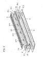
- Fig. 3 shows the items of a system for forming a shower channel 4 for floor-level showers.
- a shower channel 4 is, for example, in the recess 3, 3 'of the support element 2, 2' of the shower tray element 1, 1 'according to the invention used (see. FIGS. 1 and 2 ).
- the system comprises a gutter module 4.5, a frame 8 and a grate 9, wherein on the gutter module 4.5 a smell trap (not shown) is connected or can be connected.
- the channel module 4.5 has a cup-shaped channel 4.6 with a drain opening 5, wherein the channel bottom to the drain opening 5 is formed with a slope.
- a drain pipe connects.
- a hair sieve (not shown) can be used.
- the frame 8 can be placed on the elongate channel module 4.5 and, like the channel module 4.5, has a circumferential flange.
- the gutter flange 6 is wider than the frame flange 8.3 formed.
- the frame 8 has on its four inner sides in each case a projection 8.4, 8.5 which projects downwards and engages in the channel 4.6 of the channel module when the frame 8 is placed on the channel module 4.5.
- the longitudinal projections 8.4 of the frame 8 have inwardly angled projections 8.41, which serve to support the grate 9.
- the mutually spaced projections 8.41 are tooth-like before the projections 8.4.
- the grate 9 has a substantially U-shaped cross-sectional profile with a perforated base plate 9.3 and two thereof angled, downwardly directed legs 9.4, which are preferably unperforated. In the inserted state, the grate 9 is supported with its legs 9.4 on the projections 8.41 of the frame 8 and at the same time held laterally by the frame 8.
- support means (spacers) 10 are provided, which are arranged around the frame 8 and locked with a circumferential in the region of the outer edge of the frame 8 8.6 lip are.
- the support means 10 have substantially the shape of a cuboid and are made of plastic. However, they can also have a different geometric shape, for example the shape of a cylinder. They each have a slot into which engages the lip 8.6 of the frame 8 in the latching. Alternatively, a frictional clamping connection of support means 10 and frame 8 may be provided, wherein the slot is then designed as a clamping slot for the inserted therein frame lip 8.6.
- the support means 10 are on the channel flange 6, so that the Flange 8.3 of the frame 8 is slightly further spaced from the trough module 4.5 upwards.
- the support means 10 can be selected in their thickness so that an adaptation to the respective thickness of the proposed floor tiles or natural stone slabs is achieved.
- different thickness support means 10 of the shower channel are packed, which may for example have a thickness of 4.5 mm, 7.5 mm, 10.5 mm and 13.5 mm.
- the frame 8 After an upper-side sealing of carrier element 2, 2 'and channel flange 6 with liquid film, the frame 8 is placed on the channel module 4.5. Since the outer distances of the respectively opposing projections 8.4, 8.5 are considerably smaller than the width or the length of the channel 4.6 of the channel module 4.5, the frame 8 is displaceable on the channel flange 6 within certain limits.
- the protrusions 8.41 formed on the projections 8.4 of the frame 8 are not absolutely necessary.
- the present invention also includes the alternative of supporting the grate 9 on the bottom of the cup-shaped channel 4.6.
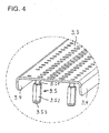
- the grate 9 is at its Bottom provided with several, for example, eight feet on which the grid 9 rests stable in the gutter module (see. Fig. 4 ).
- the adjustable feet 9.5 are height adjustable fastened to the grate 9. They have a welded to the underside of the grate 9 or molded threaded rod 9.51, to which a sleeve-shaped hex nut 9.52 is screwed. At the bottom of the hex nut 9.52 a rounded support plate 9.53 is attached
- the level of the grate 9 can be adjusted by means of the feet 9.5 relative to the channel module 4.5 and the frame 8.
- the invention is not limited in its execution to the embodiments described above. Rather, a number of variants are possible, which make use of the concept of the invention contained in the appended claims, even if they deviate.
- a plurality of separately produced shower channels 4 can also be integrated in the carrier element, wherein the shower channels are then arranged on opposite edge regions of the carrier element.
- the support element may in this case be in particular double-edged, i. be formed saddle-shaped, and then has two gradient surfaces.
- the plate-shaped support member 2, 2 ' have a shape deviating from a rectangular shape, e.g. have a round, oval or polygonal shape. It is also possible to carry out the shower channel 4 without flange 6.
Landscapes
- Health & Medical Sciences (AREA)
- Public Health (AREA)
- Epidemiology (AREA)
- General Health & Medical Sciences (AREA)
- Life Sciences & Earth Sciences (AREA)
- Engineering & Computer Science (AREA)
- Hydrology & Water Resources (AREA)
- Water Supply & Treatment (AREA)
- Sink And Installation For Waste Water (AREA)
Description
- Die Erfindung betrifft ein Duschtassenelement mit einem plattenförmigen Trägerelement aus Schaumstoff, insbesondere Hartschaumstoff, und einer Duschrinne eingesetzt im Duschtassenelement.
- Aus der
EP 1 287 213 B9 ist eine sogenannte Entwässerungsrinne bekannt, die vorrangig in häuslichen Bädern im Bereich einer bodengleichen, mit Bodenfliesen ausgestatteten Dusche eingesetzt wird. Solche länglichen rinnenförmigen Entwässerungselemente bieten gegenüber herkömmlichen relativ kleinen Bodenabläufen mehrere Vorteile. Zum einen entwässert eine solche Entwässerungsrinne die Duschfläche wesentlich schneller als ein herkömmlicher Bodenablauf. Die duschende Person steht somit nicht länger als nötig im Duschwasser. Zudem muss eine Duschrinne nicht grundsätzlich in der Mitte der Duschfläche angeordnet werden, so dass der Nutzer beim Duschen nicht unmittelbar mit dem Duschrost der Duschrinne in Berührung kommt. Herkömmliche Bodenabläufe werden zwecks guter Entwässerung in der Regel mittig angeordnet. Darüber hinaus kann eine Duschrinne (Entwässerungsrinne) auch zum Beispiel im Bereich einer gläsernen Duschtür oder Duschabtrennung angeordnet werden und somit verhindern, dass Duschwasser unter der üblicherweise verwendeten Dichtleiste der Duschtür bzw. Silikonfuge der Duschabtrennung hinwegfließen kann. - Um die Entwässerungsleistung einer Duschrinne vollständig zu nutzen, ist es wichtig, dass der Duschplatz in Richtung der Duschrinne mit Gefälle auszubilden. Dies wird herkömmlicherweise durch eine entsprechende Estrichneigung bewerkstelligt. Das Herstellen einer funktionsgerechten Estrichneigung gestaltet sich jedoch oftmals aufwendig und dementsprechend schlecht reproduzierbar. Außerdem obliegt das Herstellen der Neigung in der Regel dem Estrichleger. Das bedeutet, dass der Installateur die Verantwortung für das ordnungsgemäße Funktionieren einer Duschrinnenentwässerung ungünstigerweise an den Estrichleger abgibt.
- Aus der
DE 200 08 180 U1 ist ein aus wasserdichtem und wasserfesten Tragschaum bestehender Duschwannenträger bekannt, in den mittig ein herkömmlicher kreisförmiger Bodenablauf mit einem Geruchverschluss und ein Abflussrohr eingeschäumt sind. Auf dem Duschwannenträger ist eine rechteckige Auffangwanne angeordnet, die im Bereich des Ablaufs eine Durchlassöffnung aufweist, deren Ränder mittels einer ringförmigen Dichtung dicht mit dem Ablauf verbunden sind. Die rechteckige Auffangwanne ist durch die beiden Diagonalen in vier zum Ablauf geneigte Sektoren unterteilt. Ungünstig ist bei dieser Konstruktion unter anderem, dass die auf der Auffangwanne vorgesehenen Fliesen oder Natursteinplatten mehrfach geschnitten werden müssen, und zwar zumindest an den beiden Diagonalen der Auffangwanne. Das passgenaue Schneiden der Fliesen bzw. Natursteinplatten ist eine schwierige Arbeit, die oftmals nicht auf Anhieb gelingt und zu erheblichem Verschnitt führt. - Aus der
DE 101 31 338 A1 , die als nächstliegender Stand der Technik angesehen werden kann, ist ein aus einem Hartschaumstoff bestehendes Duschbodenelement bekannt, das einen im Wesentlichen mittig angeordneten Ablauf aufweist. Der Ablauf ist aus einem im Wesentlichen quadratischen Abflussrahmen gebildet, der beispielsweise als Spritzgussteil hergestellt ist. Zur Aufnahme des Abflussrahmens ist das Duschbodenelement mittig mit einer im Grundriss runden Öffnung versehen, welche von einer ca. 10-12 mm tiefen quadratischen Ausfräsung umgeben ist. Damit das Duschbodenelement hohe Punktlasten aufnehmen kann, ist zugeordnet zu mindestens einer seiner Randkanten eine zur Oberseite hin offene Nut ausgebildet, die materialmäßig verstärkt ausgebildet ist. - Des Weiteren ist aus der
US 2003/0033668 A1 eine Duschtasse aus polymerem Material mit Schäummittelzusätzen bekannt, die leicht in Richtung einer schmalen, länglichen Öffnung geneigt ist, durch die das Wasser in einen Sammelkanal fließen kann. Dieser Sammelkanal leitet das Wasser zu einer Ausnehmung, die sich in einer der Ecken der Duschtasse befindet, und dort in eine Ablaufvorrichtung. Sowohl die schmale, längliche Öffnung als auch der Sammelkanal sind in die Duschtasse eingeformt und somit einteilig mit der Duschtasse ausgebildet. Auf der Duschtasse sind zur Verbesserung der Rutschsicherheit kleine Rillen vorgesehen, durch die das Wasser zu der schmalen, länglichen Öffnung geführt wird. - Die
US 2006/0191067 A1 offenbart eine duschtassenförmige Vorrichtung für sanitäre Einrichtungen, die aus zwei miteinander verbindbaren Bodenteilen zusammengesetzt ist, die über einen rinnenförmigen Sammelkanal miteinander verbunden werden, wobei der Sammelkanal eine Ablauföffnung aufweist und mit einer Einlaufschlitze definierenden Abdeckung versehen ist. - Die
GB 2 315 211 A - Die
EP 1 630 309 A1 offenbart eine Duschrinne mit einer länglichen Bodenablaufrinne und einem darauf angeordneten Rostteil. Der Rostteil selbst besteht aus einem Rost und einer zweiten Ablaufrinne. Die Bodenablaufrinne weist einen Ablaufstutzen auf, in den ein an der zweiten Ablaufrinne ausgebildeter Ablaufstutzen einsteckbar ist. Zum Abdichten der Verbindung zwischen dem Rostteil und der Bodenablaufrinne ist eine Manschette vorgesehen, die in den Ablaufstutzen der Bodenablaufrinne eingesetzt wird und den an der zweiten Ablaufrinne ausgebildeten Ablaufstutzen aufnimmt. - Aufgabe der vorliegenden Erfindung ist es, den Aufbau barrierefreier bzw. bodengleicher Duschen zu erleichtern und die Dichtigkeit innerhalb des Duschtassenbereichs zu erhöhen sowie eine einfache Anpassung des Bodenablaufs an verschiedene Fliesenformate zu ermöglichen.
- Diese Aufgabe wird erfindungsgemäß durch ein Duschtassenelement mit den Merkmalen des Anspruchs 1 gelöst.
- Das erfindungsgemäße Duschtassenelement ist aus einem plattenförmigen Trägerelement aus Schaumstoff, insbesondere Hartschaumstoff gebildet. Das Trägerelement weist mindestens eine Aussparung auf, in die eine Duschrinne (Ablaufrinne) eingesetzt ist, wobei zumindest der Übergang von der Duschrinne zur Oberfläche des Trägerelementes mit einer am Rand der Duschrinne umlaufenden Abdichtung versehen ist, wobei die Duschrinne mit einem aufsetzbaren Rahmen und einem in den Rahmen einsetzbaren Rost versehen ist, wobei der Rahmen an mindestens zwei benachbarten und/oder einander gegenüberliegenden Seiten jeweils wenigstens einen Vorsprung aufweist, wobei die Vorsprünge dazu ausgebildet sind, bei auf die Duschrinne aufgesetztem Rahmen in die Duschrinne einzugreifen, und wobei die Vorsprünge so zueinander angeordnet sind, dass der auf die Duschrinne aufgesetzte Rahmen im Eingriffsbereich der Vorsprünge in mindestens einer im Wesentlichen horizontalen Richtung relativ zur Duschrinne um mindestens 10 mm verschiebbar ist. Das Trägerelement besitzt bei Auflage auf einen horizontalen Boden oder Untergrund an seiner Oberseite nur eine im Wesentlichen ebene, in Richtung der Aussparung geneigte Gefällefläche oder höchstens zwei im Wesentlichen ebene, in Richtung der Aussparung oder Aussparungen geneigte Gefälleflächen.
- Durch das erfindungsgemäße Duschtassenelement wird die Herstellung bodengleicher Duschen erheblich erleichtert. Bei Verwendung des erfindungsgemäßen Duschtassenelements kann die Zahl der auszuführenden Schnitte bzw. sichtbaren Fugenschnitte in dem auf dem Trägerelement zu verlegenden Fliesen- oder Natursteinbelag auf ein Minimum reduziert werden. Zudem stellt das erfindungsgemäße Duschtassenelement die erforderliche Dichtigkeit innerhalb des Duschtassenbereichs sicher. Ferner ermöglicht die erfindungsgemäße Ausgestaltung des Duschtassenelements eine einfache Anpassung (Ausrichtung) des der Duschrinne zugeordneten Rahmens an verschiedene Fliesenformate, da der Rahmen in mindestens einer im Wesentlichen horizontalen Richtung relativ zur Duschrinne um mindestens 10 mm verschiebbar ist.
- Eine vorteilhafte Ausgestaltung des erfindungsgemäßen Duschtassenelements sieht vor, dass der Rahmen höhenverstellbar in die Duschrinne einsteckbar ist. Diese Ausgestaltung ermöglicht eine oberflächenbündige Anpassung des Rahmens an unterschiedliche Fliesen- oder Natursteinplattendicken.
- Vorzugsweise besteht die Duschrinne (Ablaufrinne) aus einem Rinnenmodul, welches eine muldenförmige Rinne mit einer Ablauföffnung aufweist. Der Rahmen wird auf das Rinnenmodul aufgesetzt , wobei ein die Duschrinne als solche nach oben abschließender Rost in den Rahmen eingesetzt wird.
- Beim Aufsetzen des Rahmens auf das Rinnenmodul gelangen wenigstens zwei Vorsprünge, die an benachbarten und/oder an einander gegenüberliegenden Seiten des Rahmens angeordnet sind, in Eingriff mit der Rinne. Die Vorsprünge sind so zueinander angeordnet, dass der auf das Rinnenmodul aufgesetzte Rahmen im Eingriffsbereich der Vorsprünge um mindestens 10 mm in einer im wesentlichen horizontalen Richtung relativ zum Rinnenmodul verschiebbar ist. Es kommt daher nicht zu einem Reibschluss oder einem Verkeilen zwischen dem Rahmen und dem Rinnenmodul. Vielmehr sitzt der Rahmen locker auf dem Rinnenmodul auf und kann deshalb leicht in Richtung des einen oder des anderen Vorsprungs verschoben werden, bis einer der Vorsprünge an dem Rinnenmodul bzw. der Rinne zur Anlage kommt und dadurch ein weiteres Verschieben des Rahmens verhindert wird.
- Im Ergebnis ist somit noch eine Justierung des Rahmens und damit des Rosts möglich. Mit anderen Worten kann zunächst der Einbau des Duschentassenelements unkompliziert und schnell erfolgen, da dessen Position nur in etwa mit einer vorbestimmten Einbauposition übereinstimmen muss. Dies wirkt sich jedoch nicht negativ auf die Optik und die Funktion der späteren bodengleichen Dusche aus, da anschließend über den Rahmen noch eine Feinjustierung vorgenommen werden kann. Besonders vorteilhaft ist es, dass die Feinjustierung des Rahmens sehr viel einfacher bewerkstelligt werden kann als eine Feinjustierung beim Einbau des Rinnenmoduls.
- Bei Duschrinnen bodengleicher Duschen handelt es sich um solche einer länglichen Bauart mit zwei einander gegenüberliegenden Längsseiten und zwei einander gegenüberliegenden Querseiten. Dementsprechend ist dann sowohl das Rinnenmodul als auch der Rahmen und der Rost länglich ausgebildet, wobei jedes Bauteil entsprechende Längs- und Querseiten aufweist.
- Im Zusammenhang mit länglichen Duschrinnen einer rechteckigen Bauart ist es bevorzugt, wenn der Rahmen einerseits an zwei einander gegenüberliegenden Längsseiten wenigstens zwei Vorsprünge aufweist, deren äußerer Abstand um mindestens 10 mm kleiner ist als die entsprechende Innenabmessung der Rinne, und andererseits an zwei einander gegenüberliegenden Querseiten wenigstens zwei Vorsprünge aufweist, deren äußerer Abstand um mindestens 10 mm kleiner ist als die entsprechende Innenabmessung der Rinne. Auf diese Weise ist ein Ausgleich oder eine Feinjustierung in einer Längsrichtung und noch dazu alternativ oder zusätzlich in einer Querrichtung möglich. Durch eine Überlagerung beider Bewegungsrichtungen kann der Rahmen auf dem Rinnenmodul bzw. in der Rinne in alle Richtungen parallel zu der Ebene des Bodens bewegt werden.
- Bei einer weiter bevorzugten Ausführungsform des erfindungsgemäßen Duschtassenelements sind an dem Rahmen der Duschrinne umlaufende Vorsprünge vorgesehen. Stoßen die umlaufend angeordneten Vorsprünge an den Kanten des Rahmens aneinander, so ergibt sich letztlich ein einziger umlaufender Vorsprung, der sich aus den einzelnen Vorsprüngen ergibt. In diesem Fall wird eine größere Stabilität nicht nur der Vorsprünge, sondern auch des Rahmens erzielt, wodurch beispielsweise auch Materialkosten eingespart werden können.
- Besonders bevorzugt ist es, wenn die Duschrinne einen Rinnenflansch und der Rahmen einen Rahmenflansch aufweisen, so dass der Rahmenflansch bei aufgesetztem Rahmen den Rinnenflansch zumindest teilweise überdeckt. Der Rahmen kann dann stets sicher auf dem Rinnenmodul der Duschrinne abgestützt werden, auch wenn der Rahmen aus der zentralen Lage bis in eine Randlage verschoben wird. Es versteht sich, dass die Breite des Rahmenflanschs dabei an die Differenz zwischen der Breite/Länge der Rinne und den äußeren Abstand der Vorsprünge angepasst ist.
- Um nach dem Einbau des Duschtassenelements die Lage des Rosts der Duschrinne sowohl in einer Ebene parallel zum Boden als auch in einer Richtung senkrecht dazu anpassen zu können, sieht die Erfindung ferner vor, dass an dem Rahmen oder dem Rinnenmodul wenigstens ein Auflagemittel zur Höhenanpassung des Rahmens über dem Rinnenmodul angebracht werden kann. Bei einem derartigen Auflagemittel handelt es sich mit anderen Worten um eine Art Abstandshalter zwischen dem Rahmen und dem Rinnenmodul. Für den Fall, dass abweichend von einer ursprünglich geplanten Fliesendicke später dickere Fliesen oder dickere Platten aus Naturstein vorgesehen sind, wird die Höhe des abschließend aufgesetzten Rosts durch das wenigstens eine Auflagemittel, das zwischen dem Rinnenmodul und dem Rahmen vorgesehen wird, einfach angepasst. Der auf den Rahmen aufgesetzte Rost schließt dann bündig mit den Fliesen bzw. Natursteinplatten ab. Es versteht sich, dass das wenigstens eine Auflagemittel in diesem Fall Bestandteil des erfindungsgemäßen Duschtassenelements bzw. Bestandteil eines entsprechenden erfindungsgemäßen Duschtassensystems ist.
- Eine besonders hohe Flexibilität wird erreicht, wenn die Duschrinne unterschiedliche, in ihren Abmessungen standardisierte Auflagemittel umfasst. Die Auflagemittel können bei dieser besonders bevorzugten Ausgestaltung der Erfindung an verschiedene, häufig verwendete oder standardisierte Fliesenstärken angepasst sein.
- Hinsichtlich der Handhabung ist es bevorzugt, wenn das wenigstens eine Auflagemittel mit dem Rahmen oder dem Rinnenmodul verbunden werden kann bevor der Rahmen auf das Rinnenmodul aufgesetzt wird. Besonders bevorzugt ist es, wenn das Auflagemittel mit dem Rahmen oder dem Rinnenmodul ohne spezielles Werkzeug verrastbar ausgebildet ist. Ein ungewolltes Lösen des Auflagemittels wird durch das Verrasten verhindert.
- Darüber hinaus bietet es sich an, dass der Rahmen oder das Rinnenmodul wenigstens eine Lippe zum Einrasten des wenigstens einen Auflagemittels aufweist. Eine derartige Lippe lässt sich konstruktiv einfach realisieren.
- Wird die Lippe zudem im Wesentlichen umlaufend am Rahmen oder am Rinnenmodul vorgesehen, dann kann der Anwender vor Ort entscheiden, an welchen Stellen das oder die Auflagemittel vorgesehen werden. Zudem erhöht eine umlaufende Lippe die Biegesteifigkeit des Rahmens bzw. Rinnenmoduls.
- Alternativ kann das wenigstens eine Auflagemittel auch derart ausgebildet sein, dass es an dem Rahmen oder Rinnenmodul reibschlüssig anklemmbar ist. Hierzu kann das Auflagemittel vorzugsweise einen Klemmschlitz aufweisen.
- Bei einer bevorzugten Ausgestaltung weist das wenigstens eine Auflagemittel im Wesentlichen die Form eines Quaders auf. Das Auflagemittel besteht vorzugsweise aus Kunststoff. Um den Rost in die richtige Lage zu bringen, werden mehrere kompakte Auflagemittel an dem Rahmen oder dem Rinnenmodul vorgesehen, sodass der Rahmen stabil auf dem Rinnenmodul aufsitzt. Alternativ könnte natürlich auch ein umlaufendes Auflagemittel verwendet werden, das allerdings mehr Platz und Material erfordern würde und daher weniger bevorzugt ist.
- In bevorzugter Ausgestaltung der Duschrinne weisen die Vorsprünge des Rahmens nach innen abgewinkelte Auskragungen zur Abstützung des Rosts auf. Der Rost wird dann auf die Auskragungen der Vorsprünge aufgesetzt, wobei der Rost seitlich vom Rahmen gehalten wird. Der Rost ist dabei vorzugsweise reibschlüssig im Rahmen eingefasst. Der Rost kann dadurch nicht versehentlich verrutschen und dennoch zu Reinigungszwecken leicht entnommen werden.
- Weitere bevorzugte und vorteilhafte Ausgestaltungen des erfindungsgemäßen Duschtassenelements sind in den Unteransprüchen angegeben.
- Nachfolgend wird die Erfindung anhand einer mehrere Ausführungsbeispiele darstellenden Zeichnung näher erläutert. Es zeigen:
- Fig. 1
- eine perspektivische Ansicht eines plattenförmigen Trägerelements mit einer darin eingesetzten Duschrinne;
- Fig. 2
- eine perspektivische Ansicht eines anderen plattenförmigen Trägerelements mit integrierter Duschrinne gemäß einem zweiten Ausführungsbeispiel;
- Fig. 3
- eine längliche Duschrinne in einer perspektivischen Explosionsdarstellung; und
- Fig. 4
- eine perspektivische Detailansicht eines Rostes einer Duschrinne.
- In
Fig. 1 ist ein erfindungsgemäßes Duschtassenelement 1 schematisch dargestellt. Das Duschtassenelement 1 besteht im wesentlichen aus einem plattenförmigen, geschäumten Trägerelement 2 mit einer Aussparung 3, in die eine längliche Duschrinne 4 eingesetzt ist. Die Duschrinne 4 ist vorzugsweise aus Edelstahl oder Kunststoff hergestellt. - Bei dem plattenförmigen Trägerelement 2 handelt es sich um ein sogenanntes Duschboard, das üblicherweise aus Hartschaum, beispielsweise aus Styrolpolymerisat hergestellt ist. Die Oberseite des Trägerelements 2 ist in diesem Ausführungsbeispiel leicht V-förmig gemuldet ausgebildet. Die im Wesentlichen ebenen Muldenflanken sind in Richtung zur Aussparung 3 hin geneigt. Die Neigung der beiden Gefälleflächen (Muldenflanken) sind durch die Pfeile 14.1 und 14.2 gekennzeichnet. Die Aussparung 3 kann in dem Duschboard 2 insbesondere mittels geeigneter Schneidwerkzeuge hergestellt werden. Alternativ ist es auch möglich, die Aussparung 3 bereits bei der Herstellung des Duschboards, also beim Schäumvorgang auszubilden. Letzteres hat den Vorteil einer im wesentlichen abfallfreien Produktion, bei der das sonst für die Herstellung der Aussparung auszuschneidene Material eingespart wird.
- Die in die Aussparung 3 eingesetzte längliche Duschrinne 4 weist in den dargestellten Ausführungsbeispielen einen trichterartigen Boden auf. Etwa in der Mitte des Rinnenbodens ist eine Ablauföffnung 5 ausgebildet, die vorzugsweise durch einen Ablaufstutzen gebildet ist.
- Die Duschrinne 4 bzw. deren Rinnenkörper ist in die Aussparung 3 vorzugsweise eingeklebt.
- Die Duschrinne 4 weist einen umlaufenden Flansch 6 auf, der im wesentlichen bündig mit der Oberfläche des Trägerelementes 2 abschließt. Die Oberfläche des Trägerelements 2 und der Rinnenflansch 6 sind mit einer Dichtungsfolie (nicht gezeigt), vorzugsweise einer flüssig aufgetragenen Dichtungsfolie beschichtet und somit abgedichtet. In diesem Zustand kann das erfindungsgemäße Duschtassenelement 1 bzw. 1' an den Installateur bzw. Endkunden verkauft werden.
- Die Duschrinne 4 umfasst einen darin einsteckbaren Rahmen (nicht gezeigt) sowie einen in den Rahmen einlegbaren Rost (nicht gezeigt). Der Rahmen ist vorzugsweise höhenverstellbar und/oder seitenverstellbar in die Duschrinne 4 einsteckbar. Hierdurch kann die Duschrinne 4 bzw. deren Rost an unterschiedlichen Fliesen- oder Natursteinstärken bzw. an ein Fugengitter (Fliesenraster) angepasst werden. Um eine Höhenverstellung des Rahmens zu ermöglichen, weist der Rinnenkörper an seiner Innenwandung einen umlaufenden Absatz 7 auf, in den der Rahmen mit einem an seiner Unterseite ausgebildeten Kragen formschlüssig und/oder reibschlüssig eingreift. Der Installateur bzw. Kunde legt nach Einbau des Duschtassenelements 1 bzw. 1' den Rahmen auf die Duschrinne 4, richtet den Rahmen aus und verfliest das plattenförmige Trägerelement 2, 2'.
- Das plattenförmige Trägerelement 2, 2' ist vorzugsweise so ausgebildet, dass es bei Auflage auf einen im wesentlichen horizontalen Boden oder Untergrund an seiner Oberseite ein Gefälle in Richtung der Aussparung 3, 3' aufweist.
- Bei dem in
Fig. 1 dargestellten Ausführungsbeispiel ist die Aussparung 3 mit der Duschrinne 4 etwa in der Mitte des Duschboards 2 angeordnet. - In dem in
Fig. 2 schematisch gezeigten Ausführungsbeispiel ist dagegen die Aussparung 3' mit der Duschrinne 4 im Randbereich eines Duschboards 2' angeordnet. Das Trägerelement 2' ist in diesem Ausführungsbeispiel einkeilig ausgebildet. Die Richtung der zur Aussparung 3' hin geneigten Gefällefläche des Trägerelements 2' ist durch den Pfeil 14 gekennzeichnet. -
Fig. 3 zeigt die Einzelteile eines Systems zur Bildung einer Duschrinne 4 für bodengleiche Duschen. Eine solche Duschrinne 4 ist beispielsweise in die Aussparung 3, 3' des Trägerelements 2, 2' des erfindungsgemäßen Duschtassenelements 1, 1' eingesetzt (vgl.Figuren 1 und2 ). Das System umfasst ein Rinnenmodul 4.5, einen Rahmen 8 und einen Rost 9, wobei an dem Rinnenmodul 4.5 ein Geruchverschluss (nicht gezeigt) angeschlossen ist bzw. anschließbar ist. - Mit 15 ist eine schalenförmige Abdeckung bezeichnet, die zum Schutz des Rinnenmoduls 4.5 vor einer Verstopfung durch Estrich, Mörtel oder andere Materialien während der Bauphase dient und den Rinnenflansch vor Verunreinigungen schützt. Hierzu wird die Abdeckung 15 formschlüssig in das Rinnenmodul 4.5 eingesetzt. Das Rinnenmodul 4.5 weist eine schalenförmige Rinne 4.6 mit einer Ablauföffnung 5 auf, wobei der Rinnenboden zur Ablauföffnung 5 hin mit Gefälle ausgebildet ist. An die Ablauföffnung 5 schließt sich ein Ablaufstutzen an. In die Ablauföffnung 5 bzw. den Ablaufstutzen ist ein Haarsieb (nicht gezeigt) einsetzbar .
- Auf das längliche Rinnenmodul 4.5 kann nach Entfernen der Abdeckung 15 der Rahmen 8 aufgesetzt werden, der wie das Rinnenmodul 4.5 einen umlaufenden Flansch aufweist. Der Rinnenflansch 6 ist dabei breiter als der Rahmenflansch 8.3 ausgebildet. Der Rahmen 8 weist an seinen vier Innenseiten jeweils einen Vorsprung 8.4, 8.5 auf, der nach unten vorsteht und in die Rinne 4.6 des Rinnenmoduls eingreift, wenn der Rahmen 8 auf das Rinnenmodul 4.5 gesetzt wird.
- Die längsseitigen Vorsprünge 8.4 des Rahmens 8 weisen nach innen abgewinkelte Auskragungen 8.41 auf, die der Abstützung des Rosts 9 dienen. Die zueinander beabstandeten Auskragungen 8.41 stehen zahnartig an den Vorsprüngen 8.4 vor. Der Rost 9 besitzt ein im Wesentlichen U-förmiges Querschnittsprofil mit einer gelochten Grundplatte 9.3 und zwei davon abgewinkelten, nach unten gerichteten Schenkeln 9.4, die vorzugsweise ungelocht sind. Im eingesetzten zustand wird der Rost 9 mit seinen Schenkeln 9.4 auf den Auskragungen 8.41 des Rahmens 8 abgestützt und gleichzeitig seitlich vom Rahmen 8 gehalten.
- Zur Anpassung der Einbauhöhe des Rahmens 8 bzw. Rostes 9 an unterschiedliche Fliesenstärken bzw. unterschiedlich dicke Natursteinplatten sind mehrere Auflagemittel (Abstandselemente) 10 vorgesehen, die rings um den Rahmen 8 angeordnet und mit einer im Bereich des äußeren Randes des Rahmens 8 umlaufenden Lippe 8.6 verrastet sind.
- Die Auflagemittel 10 haben im Wesentlichen die Form eines Quaders und sind aus Kunststoff gefertigt. Sie können allerdings auch eine andere geometrische Form aufweisen, beispielsweise die Form eines Zylinders. Sie weisen jeweils einen Schlitz auf, in den die Lippe 8.6 des Rahmens 8 bei der Verrastung eingreift. Alternativ kann auch eine reibschlüssige Klemmverbindung von Auflagemittel 10 und Rahmen 8 vorgesehen werden, wobei der Schlitz dann als Klemmschlitz für die darin einzusetzende Rahmenlippe 8.6 ausgeführt ist.
- Im zusammengebauten Zustand der Duschrinne 4 liegen die Auflagemittel 10 auf dem Rinnenflansch 6 auf, so dass der Flansch 8.3 des Rahmens 8 etwas weiter von dem Rinnenmodul 4.5 nach oben beabstandet ist. Die Auflagemittel 10 können dabei in ihrer Dicke so gewählt werden, dass eine Anpassung an die jeweilige Dicke der vorgesehenen Bodenfliesen bzw. Natursteinplatten erzielt wird. Hierzu werden verschieden dicke Auflagemittel 10 der Duschrinne beigepackt, die beispielsweise eine Dicke von 4,5 mm, 7,5 mm, 10,5 mm und 13,5 mm aufweisen können.
- Nach einer oberseitigen Abdichtung von Trägerelement 2, 2' und Rinnenflansch 6 mit Flüssigfolie wird der Rahmen 8 auf das Rinnenmodul 4.5 aufgesetzt. Da die äußeren Abstände der jeweils einander gegenüberliegenden Vorsprünge 8.4, 8.5 erheblich kleiner sind als die Breite bzw. die Länge der Rinne 4.6 des Rinnenmoduls 4.5, liegt der Rahmen 8 in gewissen Grenzen verschieblich auf dem Rinnenflansch 6 auf.
- Dies ermöglicht dann eine Anpassung der Lage des Rahmens 8 bezüglich angrenzend verlegter Fliesen, ohne dass die Lage des Rinnenmoduls 4.5 nachträglich verändert werden muss. Es wird der Rahmen 8 einfach in die gewünschte Position gebracht, bevor dort dann der die Duschrinne 4 nach oben abschließende Rost 9 angebracht wird. Wie weit der Rahmen 8 verschoben werden kann, hängt letztlich von dem äußeren Abstand der Vorsprünge ab. Einige Millimeter, d.h. mindestens 10 mm sind hier jedoch zumeist ausreichend.
- Die an den Vorsprüngen 8.4 des Rahmens 8 ausgebildeten Auskragungen 8.41 sind nicht zwingend erforderlich. Die vorliegende Erfindung umfasst auch die Alternative, den Rost 9 auf dem Boden der schalenförmigen Rinne 4.6 abzustützen. In diesem Fall ist der Rost 9 an seiner Unterseite mit mehreren, beispielsweise acht Stellfüßen versehen, auf denen der Rost 9 stabil in dem Rinnenmodul aufliegt (vgl.
Fig. 4 ). Die Stellfüße 9.5 sind dabei höhenverstellbar am Rost 9 befestigt. Sie weisen eine an die Unterseite des Rosts 9 angeschweißte oder angeformte Gewindestange 9.51 auf, auf die eine hülsenförmige Sechskantmutter 9.52 aufgeschraubt ist. An der Unterseite der Sechskantmutter 9.52 ist eine abgerundete Auflagescheibe 9.53 angebracht - Das Niveau des Rosts 9 lässt sich mittels der Stellfüße 9.5 relativ zum Rinnenmodul 4.5 sowie zum Rahmen 8 justieren.
- Die Erfindung ist in ihrer Ausführung nicht auf die vorstehend beschriebenen Ausführungsbeispiele beschränkt. Vielmehr sind eine Reihe von Varianten möglich, die auch bei abweichender Gestaltung von dem in den beigefügten Ansprüchen enthaltenen Erfindungsgedanken Gebrauch machen. So können zum Beispiel in dem plattenförmigen Trägerelement 2, 2' auch mehrere separat hergestellte Duschrinnen 4 integriert sein. Vorzugsweise können in dem Trägerelement zwei längliche, parallel zueinander verlaufende Duschrinnen 4 integriert sein, wobei die Duschrinnen dann an gegenüberliegenden Randbereichen des Trägerelements angeordnet sind. Das Trägerelement kann in diesem Fall insbesondere zweikeilig, d.h. sattelförmig ausgebildet sein, und weist dann zwei Gefälleflächen auf. Auch kann das plattenförmige Trägerelement 2, 2', eine von einer rechteckigen Form abweichende Form aufweisen, z.B. eine runde, ovale oder polygonale Form besitzen. Auch ist es möglich, die Duschrinne 4 ohne Flansch 6 auszuführen.
Claims (16)
- Duschtassenelement (1, 1') mit einem plattenförmigen Trägerelement (2, 2') aus Schaumstoff, insbesondere Hartschaumstoff, das mindestens eine Aussparung (3, 3') aufweist, dadurch gekennzeichnet, dass in die mindestens eine Aussparung (3, 3') eine längliche Duschrinne (4) eingesetzt ist, wobei das Trägerelement bei Auflage auf einen horizontalen Boden oder Untergrund an seiner Oberseite nur eine im wesentlichen ebene, in Richtung der Aussparung (3, 3') geneigte Gefällefläche oder höchstens zwei im wesentlichen ebene, in Richtung der Aussparung (3, 3') oder Aussparungen geneigte Gefälleflächen aufweist, wobei der Übergang von der Duschrinne (4) zur Oberfläche des Trägerelements (2, 2') mit einer am Rand der Duschrinne (4) umlaufenden Abdichtung versehen ist, wobei die Duschrinne (4) mit einem aufsetzbaren Rahmen (8) und einem in den Rahmen einsetzbaren Rost (9) versehen ist, wobei der Rahmen (8) an mindestens zwei benachbarten und/oder einander gegenüberliegenden Seiten jeweils wenigstens einen Vorsprung (8.4, 8.5) aufweist, wobei die Vorsprünge (8.4, 8.5) dazu ausgebildet sind, bei auf die Duschrinne (4) aufgesetztem Rahmen (8) in die Duschrinne einzugreifen, und wobei die Vorsprünge (8.4, 8.5) so zueinander angeordnet sind, dass der auf die Duschrinne aufgesetzte Rahmen (8) im Eingriffsbereich der Vorsprünge (8.4, 8.5) in mindestens einer im Wesentlichen horizontalen Richtung relativ zur Duschrinne (4) um mindestens 10 mm verschiebbar ist.
- Duschtassenelement nach Anspruch 1,
dadurch gekennzeichnet, dass
die Duschrinne (4) in die Aussparung (3, 3') eingeklebt ist. - Duschtassenelement nach Anspruch 1 oder 2,
dadurch gekennzeichnet, dass
die Duschrinne einen Flansch (6) aufweist, wobei die Oberfläche des Trägerelements (2, 2') und der Flansch (6) mit einer Dichtungsfolie, vorzugsweise einer flüssig aufgetragenen Dichtungsfolie beschichtet sind. - Duschtassenelement nach Anspruch 3,
dadurch gekennzeichnet, dass
der Flansch (6) der Duschrinne im Wesentlichen bündig mit der Oberfläche des Trägerelementes (2, 2') abschließt. - Duschtassenelement nach einem der Ansprüche 1 bis 4,
dadurch gekennzeichnet, dass
der Rahmen (8) höhenverstellbar in die Duschrinne (4) einsteckbar ist. - Duschtassenelement nach einem der Ansprüche 1 bis 5,
dadurch gekennzeichnet, dass
das Trägerelement (2, 2') mehrere Aussparungen (3, 3') aufweist, in denen jeweils eine Duschrinne (4) eingesetzt ist. - Duschtassenelement nach einem der Ansprüche 1 bis 6,
dadurch gekennzeichnet, dass
das Trägerelement (2, 2') einkeilig oder zweikeilig ausgebildet ist. - Duschtassenelement nach Anspruch 1 oder 2,
dadurch gekennzeichnet, dass
die Duschrinne (4) einen Rinnenflansch (6) und der Rahmen (8) einen Rahmenflansch (8.3) aufweist, wobei der Rahmenflansch (8.3) bei aufgesetztem Rahmen (8) den Rinnenflansch (6) zumindest teilweise überdeckt. - Duschtassenelement nach einem der Ansprüche 1 bis 8,
dadurch gekennzeichnet, dass an dem Rahmen (8) oder der Duschrinne (4) wenigstens ein Auflagemittel (10), zur Höhenanpassung des Rahmens (8) über der Duschrinne (4) vorgesehen ist. - Duschtassenelement nach Anspruch 9,
dadurch gekennzeichnet, dass das wenigstens eine Auflagemittel (10) mit dem Rahmen (8) oder der Duschrinne (4) verrastbar ist. - Duschtassenelement nach Anspruch 9 oder 10,
dadurch gekennzeichnet, dass der Rahmen (8) oder die Duschrinne (4) wenigstens eine Lippe (8.6) zum Einrasten des wenigstens einen Auflagemittels (10). aufweist. - Duschtassenelement nach Anspruch 9,
dadurch gekennzeichnet, dass das wenigstens eine Auflagemittel (10) an dem Rahmen (8) oder der Duschrinne (4) als reibschlüssige Klemmverbindung vorgesehen ist. - Duschtassenelement nach Anspruch 12,
dadurch gekennzeichnet, dass das wenigstens eine Auflagemittel (10) einen Klemmschlitz aufweist. - Duschtassenelement nach einem der Ansprüche 9 bis 13,
dadurch gekennzeichnet, dass das wenigstens eine Auflagemittel (10) im Wesentlichen die Form eines Quaders oder Zylinders aufweist. - Duschtassenelement nach einem der Ansprüche 1 bis 14,
dadurch gekennzeichnet, dass
die Vorsprünge (8.4) des Rahmens (8) nach innen abgewinkelte Auskragungen (8.41) zur Abstützung des Rosts (9) aufweisen. - Duschtassenelement nach einem der Ansprüche 1 bis 15,
dadurch gekennzeichnet, dass
der Rost (9) mit höhenverstellbaren Füßen (9.5) versehen ist, über die er in der Duschrinne (4) abgestützt ist.
Priority Applications (1)
| Application Number | Priority Date | Filing Date | Title |
|---|---|---|---|
| PL06123363T PL1782721T3 (pl) | 2005-11-02 | 2006-11-02 | Brodzik prysznicowy z rynną odpływową |
Applications Claiming Priority (4)
| Application Number | Priority Date | Filing Date | Title |
|---|---|---|---|
| DE202005017218 | 2005-11-02 | ||
| DE202005018838U DE202005018838U1 (de) | 2005-11-02 | 2005-12-01 | Duschtassenelement mit einem plattenförmigen Trägerelement aus Schaumstoff |
| DE202006002077U DE202006002077U1 (de) | 2006-02-08 | 2006-02-08 | Ablaufrinne und System zur Bildung eines Wasserablaufs, vorzugsweise für bodengleiche Duschen |
| DE202006003720U DE202006003720U1 (de) | 2005-11-02 | 2006-03-07 | Duschtassenelement mit einem plattenförmigen Trägerelement aus Schaumstoff |
Publications (3)
| Publication Number | Publication Date |
|---|---|
| EP1782721A2 EP1782721A2 (de) | 2007-05-09 |
| EP1782721A3 EP1782721A3 (de) | 2008-01-23 |
| EP1782721B1 true EP1782721B1 (de) | 2015-07-29 |
Family
ID=37672329
Family Applications (1)
| Application Number | Title | Priority Date | Filing Date |
|---|---|---|---|
| EP06123363.1A Active EP1782721B1 (de) | 2005-11-02 | 2006-11-02 | Duschtassenelement mit einer Ablaufrinne |
Country Status (6)
| Country | Link |
|---|---|
| EP (1) | EP1782721B1 (de) |
| DK (1) | DK1782721T3 (de) |
| ES (1) | ES2548727T3 (de) |
| HU (1) | HUE027969T2 (de) |
| PL (1) | PL1782721T3 (de) |
| PT (1) | PT1782721E (de) |
Cited By (1)
| Publication number | Priority date | Publication date | Assignee | Title |
|---|---|---|---|---|
| CN104295123A (zh) * | 2014-09-28 | 2015-01-21 | 周伟 | 一种可防臭的淋浴房底座 |
Families Citing this family (24)
| Publication number | Priority date | Publication date | Assignee | Title |
|---|---|---|---|---|
| SE0701839L (sv) * | 2007-08-08 | 2008-12-16 | Purus Ab | Avlopp |
| DE102008046671A1 (de) | 2007-11-30 | 2009-06-04 | Dallmer Gmbh & Co. Kg | Ablaufvorrichtung |
| DE202008015899U1 (de) | 2008-02-01 | 2009-04-23 | Illbruck Sanitärtechnik GmbH | Duschbodenelement |
| DE202008003050U1 (de) | 2008-03-04 | 2008-07-03 | Mepa - Pauli Und Menden Gmbh | Duschrinnenanordnung |
| EP2153767A3 (de) * | 2008-08-15 | 2012-05-09 | Masco Bath Corporation | Wannensystem |
| DE202008011038U1 (de) | 2008-08-19 | 2008-12-24 | Frank Huster Prof. freier Architekt GbR (vertretungsberechtigter Gesellschafter: Frank Huster, 01309 Dresden) | Grundkörper für bodenebene Duschtassen |
| GB2463331B (en) * | 2008-09-16 | 2011-01-12 | Ccl Specialist Supplies Ltd | Wet area floor former system |
| DE102008052285B4 (de) * | 2008-10-18 | 2014-01-30 | Dallmer Gmbh & Co. Kg | Ablaufvorrichtung |
| US8661574B2 (en) | 2009-02-10 | 2014-03-04 | Purus Ab | Drain and inlet member for drain |
| DE202009003121U1 (de) | 2009-03-09 | 2010-04-29 | Mepa - Pauli Und Menden Gmbh | Befliesbare Stützvorrichtung |
| NL2003590C2 (nl) * | 2009-10-05 | 2011-04-06 | Easy Sanitary Solutions B V | Afvoer, zoals een douchegoot, met variabele afmetingen. |
| US8677521B2 (en) * | 2009-10-15 | 2014-03-25 | Dlp Limited | Shower floor formers |
| NL2004076C2 (nl) | 2010-01-07 | 2011-07-11 | Easy Sanitary Solutions B V | Gekromde tegel. |
| DE202010007534U1 (de) | 2010-06-02 | 2010-09-02 | Wedi, Stephan | Entwässerungsablauf zum Einbau in eine Bodenöffnung eines Duschplatzes |
| NL2005864C2 (nl) * | 2010-12-16 | 2012-06-19 | Easy Sanitairy Solutions Bv | Vlakke plaat goot. |
| DE202011004001U1 (de) | 2011-03-15 | 2012-07-05 | Mepa-Pauli Und Menden Gmbh | Ablaufanordnung |
| DE102012104347A1 (de) | 2011-06-28 | 2013-01-03 | Illbruck Sanitärtechnik GmbH | Duschbodenelement |
| DE202011051047U1 (de) | 2011-08-19 | 2012-11-28 | Mepa-Pauli Und Menden Gmbh | Ablaufanordnung |
| DE102012110726A1 (de) | 2011-11-10 | 2013-05-16 | Poresta Systems Gmbh | Duschbodenelement und Einbauset für ein Duschbodenelement |
| DE202012100725U1 (de) | 2011-11-10 | 2013-02-14 | Poresta Systems Gmbh | Duschbodenelement und Einbauset für ein Duschbodenelement |
| EP2591709B1 (de) | 2011-11-10 | 2018-03-21 | poresta systems GmbH | Duschbodenelement und Einbauset für ein Duschbodenelement |
| FR3080878B1 (fr) * | 2018-05-07 | 2021-05-14 | Abpool | Piece de maintien d'un element de couverture d'une goulotte pour piscine a debordement. |
| DE102018132112A1 (de) * | 2018-12-13 | 2020-06-18 | Richard Brink Gmbh & Co. Kg | Bodenaufbau einer Dusche |
| EP4202136A1 (de) * | 2021-12-24 | 2023-06-28 | Progress Profiles SPA | Duschablaufanordnung und bausatz zu deren einbau |
Family Cites Families (13)
| Publication number | Priority date | Publication date | Assignee | Title |
|---|---|---|---|---|
| DE3809068A1 (de) * | 1988-03-18 | 1989-09-28 | Peter Josef Korzilius Soehne G | Duschtasse |
| GB9220511D0 (en) * | 1992-09-29 | 1992-11-11 | Eastbourne Showers Ltd | Shower tray |
| GB2315211B (en) | 1996-07-12 | 2000-11-22 | Beldore Ltd | Waste water outlet and trap for a low level shower tray |
| US6381773B1 (en) | 1998-05-06 | 2002-05-07 | Aquabath, Inc | Base for barrier-free shower enclosure |
| US6178571B1 (en) * | 1997-05-09 | 2001-01-30 | Aqua Bath, Inc. | Barrier-free shower system |
| DE20008180U1 (de) | 2000-05-06 | 2000-08-03 | Koralle Sanitärprodukte GmbH, 32602 Vlotho | Duschwanne |
| DE10131338B4 (de) | 2001-03-07 | 2011-01-13 | Illbruck Sanitärtechnik GmbH | Duschbodenelement aus Hartschaumstoff |
| ES1050210Y (es) | 2001-05-31 | 2002-07-01 | Pane Enrique Graells | Plataforma de ducha. |
| DE10306120A1 (de) * | 2001-09-20 | 2004-08-26 | Mehdi Ghetmiri | Bodenbündiger Duschplatz |
| DE10360310A1 (de) | 2003-12-18 | 2005-07-21 | Dallmer Gmbh & Co. Kg | Ablaufvorrichtung |
| NZ531166A (en) * | 2004-02-13 | 2006-10-27 | Kohler New Zealand Ltd | A Shower Enclosure and Shower Base |
| DE202005003399U1 (de) | 2005-02-17 | 2005-05-25 | Schulte Duschkabinenbau Gmbh & Co. Kg | Duschbodenelement und Duschbodenaufbau |
| ITMI20050302A1 (it) | 2005-02-25 | 2006-08-26 | American Standard Europ Sprl | Dispositivo di convogliamento e scarico dell'acqua |
-
2006
- 2006-11-02 EP EP06123363.1A patent/EP1782721B1/de active Active
- 2006-11-02 PL PL06123363T patent/PL1782721T3/pl unknown
- 2006-11-02 HU HUE06123363A patent/HUE027969T2/en unknown
- 2006-11-02 PT PT61233631T patent/PT1782721E/pt unknown
- 2006-11-02 DK DK06123363.1T patent/DK1782721T3/en active
- 2006-11-02 ES ES06123363.1T patent/ES2548727T3/es active Active
Cited By (1)
| Publication number | Priority date | Publication date | Assignee | Title |
|---|---|---|---|---|
| CN104295123A (zh) * | 2014-09-28 | 2015-01-21 | 周伟 | 一种可防臭的淋浴房底座 |
Also Published As
| Publication number | Publication date |
|---|---|
| HUE027969T2 (en) | 2016-11-28 |
| DK1782721T3 (en) | 2015-10-26 |
| EP1782721A3 (de) | 2008-01-23 |
| EP1782721A2 (de) | 2007-05-09 |
| PT1782721E (pt) | 2015-10-22 |
| PL1782721T3 (pl) | 2015-12-31 |
| ES2548727T3 (es) | 2015-10-20 |
Similar Documents
| Publication | Publication Date | Title |
|---|---|---|
| EP1782721A2 (de) | Trägerelement für Duschtasse | |
| EP1818464B1 (de) | Ablauf, vorzugsweise für bodengleiche Duschen | |
| EP3705655B1 (de) | Bodenablauf zum abführen von wasser von einem begehbaren boden in eine abwasserleitung | |
| WO2011104292A1 (de) | Bodenablauf mit höhenverstellbarem rahmen für einen gitterrost | |
| EP2808457A2 (de) | Wasserablaufvorrichtung für eine sanitäre Anlage, wie einen bodenebenen Duschplatz | |
| DE202011001135U1 (de) | Ablaufrinne für bodengleiche Duschen | |
| EP2540202B1 (de) | Duschbodenelement | |
| EP3366852B1 (de) | Vorrichtung für einen im boden eines raumes angeordneten bodenablauf | |
| EP2808458B1 (de) | Wasserablaufvorrichtung für eine Dusche und Duschbodenelement | |
| DE202006014440U1 (de) | Duschbodenelement aus einem Hartschaumstoff | |
| DE102011053644B4 (de) | Ablaufrinne für eine bodengleiche Dusche | |
| CH700262B1 (de) | Versenkt einbaubare Ablaufvorrichtung für einen Sanitärbereich. | |
| EP2591709B1 (de) | Duschbodenelement und Einbauset für ein Duschbodenelement | |
| DE102013100201A1 (de) | Ablaufrinne und Duschbodenelement | |
| DE102012106924A1 (de) | Ablaufanordnung | |
| EP0788755B1 (de) | Wannenträger, insbesondere Badewannen- und Duschwannenträger | |
| DE102019116655B4 (de) | Einbauhilfe für einen Bodenbelag-Begrenzungsrahmen eines Ablaufes | |
| DE202005018838U1 (de) | Duschtassenelement mit einem plattenförmigen Trägerelement aus Schaumstoff | |
| DE202017104903U1 (de) | Rostdeckel für Ablaufrinne | |
| DE202011004001U1 (de) | Ablaufanordnung | |
| EP2628855B1 (de) | Ablauf | |
| DE102017103785A1 (de) | Vorrichtung für einen im Boden eines Raumes angeordneten Bodenablauf | |
| DE202010000508U1 (de) | Ablaufvorrichtung mit Dichtzarge, insbesondere zur Verwendung in einer bodengleichen Dusche | |
| EP3666992A1 (de) | Bodenaufbau einer dusche | |
| DE202010000963U1 (de) | Duschablaufanordnung |
Legal Events
| Date | Code | Title | Description |
|---|---|---|---|
| PUAI | Public reference made under article 153(3) epc to a published international application that has entered the european phase |
Free format text: ORIGINAL CODE: 0009012 |
|
| AK | Designated contracting states |
Kind code of ref document: A2 Designated state(s): AT BE BG CH CY CZ DE DK EE ES FI FR GB GR HU IE IS IT LI LT LU LV MC NL PL PT RO SE SI SK TR |
|
| AX | Request for extension of the european patent |
Extension state: AL BA HR MK YU |
|
| PUAL | Search report despatched |
Free format text: ORIGINAL CODE: 0009013 |
|
| AK | Designated contracting states |
Kind code of ref document: A3 Designated state(s): AT BE BG CH CY CZ DE DK EE ES FI FR GB GR HU IE IS IT LI LT LU LV MC NL PL PT RO SE SI SK TR |
|
| AX | Request for extension of the european patent |
Extension state: AL BA HR MK YU |
|
| 17P | Request for examination filed |
Effective date: 20080306 |
|
| 17Q | First examination report despatched |
Effective date: 20080403 |
|
| AKX | Designation fees paid |
Designated state(s): AT BE BG CH CY CZ DE DK EE ES FI FR GB GR HU IE IS IT LI LT LU LV MC NL PL PT RO SE SI SK TR |
|
| TPAC | Observations filed by third parties |
Free format text: ORIGINAL CODE: EPIDOSNTIPA |
|
| GRAP | Despatch of communication of intention to grant a patent |
Free format text: ORIGINAL CODE: EPIDOSNIGR1 |
|
| INTG | Intention to grant announced |
Effective date: 20150401 |
|
| GRAS | Grant fee paid |
Free format text: ORIGINAL CODE: EPIDOSNIGR3 |
|
| GRAA | (expected) grant |
Free format text: ORIGINAL CODE: 0009210 |
|
| AK | Designated contracting states |
Kind code of ref document: B1 Designated state(s): AT BE BG CH CY CZ DE DK EE ES FI FR GB GR HU IE IS IT LI LT LU LV MC NL PL PT RO SE SI SK TR |
|
| REG | Reference to a national code |
Ref country code: DE Ref legal event code: R081 Ref document number: 502006014444 Country of ref document: DE Owner name: VIEGA TECHNOLOGY GMBH & CO. KG, DE Free format text: FORMER OWNER: VIEGA GMBH & CO. KG, 57439 ATTENDORN, DE Ref country code: GB Ref legal event code: FG4D Free format text: NOT ENGLISH |
|
| REG | Reference to a national code |
Ref country code: CH Ref legal event code: EP |
|
| REG | Reference to a national code |
Ref country code: AT Ref legal event code: REF Ref document number: 738602 Country of ref document: AT Kind code of ref document: T Effective date: 20150815 |
|
| REG | Reference to a national code |
Ref country code: IE Ref legal event code: FG4D Free format text: LANGUAGE OF EP DOCUMENT: GERMAN |
|
| REG | Reference to a national code |
Ref country code: DE Ref legal event code: R096 Ref document number: 502006014444 Country of ref document: DE |
|
| REG | Reference to a national code |
Ref country code: ES Ref legal event code: FG2A Ref document number: 2548727 Country of ref document: ES Kind code of ref document: T3 Effective date: 20151020 |
|
| REG | Reference to a national code |
Ref country code: PT Ref legal event code: SC4A Free format text: AVAILABILITY OF NATIONAL TRANSLATION Effective date: 20150930 |
|
| REG | Reference to a national code |
Ref country code: DK Ref legal event code: T3 Effective date: 20151020 |
|
| REG | Reference to a national code |
Ref country code: SE Ref legal event code: TRGR |
|
| REG | Reference to a national code |
Ref country code: FR Ref legal event code: PLFP Year of fee payment: 10 |
|
| REG | Reference to a national code |
Ref country code: LT Ref legal event code: MG4D |
|
| REG | Reference to a national code |
Ref country code: NL Ref legal event code: FP |
|
| REG | Reference to a national code |
Ref country code: PL Ref legal event code: T3 |
|
| PG25 | Lapsed in a contracting state [announced via postgrant information from national office to epo] |
Ref country code: LT Free format text: LAPSE BECAUSE OF FAILURE TO SUBMIT A TRANSLATION OF THE DESCRIPTION OR TO PAY THE FEE WITHIN THE PRESCRIBED TIME-LIMIT Effective date: 20150729 Ref country code: LV Free format text: LAPSE BECAUSE OF FAILURE TO SUBMIT A TRANSLATION OF THE DESCRIPTION OR TO PAY THE FEE WITHIN THE PRESCRIBED TIME-LIMIT Effective date: 20150729 Ref country code: GR Free format text: LAPSE BECAUSE OF FAILURE TO SUBMIT A TRANSLATION OF THE DESCRIPTION OR TO PAY THE FEE WITHIN THE PRESCRIBED TIME-LIMIT Effective date: 20151030 Ref country code: FI Free format text: LAPSE BECAUSE OF FAILURE TO SUBMIT A TRANSLATION OF THE DESCRIPTION OR TO PAY THE FEE WITHIN THE PRESCRIBED TIME-LIMIT Effective date: 20150729 |
|
| PG25 | Lapsed in a contracting state [announced via postgrant information from national office to epo] |
Ref country code: IS Free format text: LAPSE BECAUSE OF FAILURE TO SUBMIT A TRANSLATION OF THE DESCRIPTION OR TO PAY THE FEE WITHIN THE PRESCRIBED TIME-LIMIT Effective date: 20151129 |
|
| PG25 | Lapsed in a contracting state [announced via postgrant information from national office to epo] |
Ref country code: EE Free format text: LAPSE BECAUSE OF FAILURE TO SUBMIT A TRANSLATION OF THE DESCRIPTION OR TO PAY THE FEE WITHIN THE PRESCRIBED TIME-LIMIT Effective date: 20150729 Ref country code: SK Free format text: LAPSE BECAUSE OF FAILURE TO SUBMIT A TRANSLATION OF THE DESCRIPTION OR TO PAY THE FEE WITHIN THE PRESCRIBED TIME-LIMIT Effective date: 20150729 |
|
| REG | Reference to a national code |
Ref country code: DE Ref legal event code: R097 Ref document number: 502006014444 Country of ref document: DE |
|
| PG25 | Lapsed in a contracting state [announced via postgrant information from national office to epo] |
Ref country code: RO Free format text: LAPSE BECAUSE OF FAILURE TO SUBMIT A TRANSLATION OF THE DESCRIPTION OR TO PAY THE FEE WITHIN THE PRESCRIBED TIME-LIMIT Effective date: 20150729 |
|
| PLBE | No opposition filed within time limit |
Free format text: ORIGINAL CODE: 0009261 |
|
| STAA | Information on the status of an ep patent application or granted ep patent |
Free format text: STATUS: NO OPPOSITION FILED WITHIN TIME LIMIT |
|
| PG25 | Lapsed in a contracting state [announced via postgrant information from national office to epo] |
Ref country code: MC Free format text: LAPSE BECAUSE OF FAILURE TO SUBMIT A TRANSLATION OF THE DESCRIPTION OR TO PAY THE FEE WITHIN THE PRESCRIBED TIME-LIMIT Effective date: 20150729 Ref country code: LU Free format text: LAPSE BECAUSE OF FAILURE TO SUBMIT A TRANSLATION OF THE DESCRIPTION OR TO PAY THE FEE WITHIN THE PRESCRIBED TIME-LIMIT Effective date: 20151102 |
|
| REG | Reference to a national code |
Ref country code: CH Ref legal event code: PL |
|
| 26N | No opposition filed |
Effective date: 20160502 |
|
| GBPC | Gb: european patent ceased through non-payment of renewal fee |
Effective date: 20151102 |
|
| PG25 | Lapsed in a contracting state [announced via postgrant information from national office to epo] |
Ref country code: LI Free format text: LAPSE BECAUSE OF NON-PAYMENT OF DUE FEES Effective date: 20151130 Ref country code: CH Free format text: LAPSE BECAUSE OF NON-PAYMENT OF DUE FEES Effective date: 20151130 |
|
| REG | Reference to a national code |
Ref country code: IE Ref legal event code: MM4A |
|
| PG25 | Lapsed in a contracting state [announced via postgrant information from national office to epo] |
Ref country code: SI Free format text: LAPSE BECAUSE OF FAILURE TO SUBMIT A TRANSLATION OF THE DESCRIPTION OR TO PAY THE FEE WITHIN THE PRESCRIBED TIME-LIMIT Effective date: 20150729 |
|
| PG25 | Lapsed in a contracting state [announced via postgrant information from national office to epo] |
Ref country code: IE Free format text: LAPSE BECAUSE OF NON-PAYMENT OF DUE FEES Effective date: 20151102 Ref country code: GB Free format text: LAPSE BECAUSE OF NON-PAYMENT OF DUE FEES Effective date: 20151102 |
|
| REG | Reference to a national code |
Ref country code: HU Ref legal event code: AG4A Ref document number: E027969 Country of ref document: HU |
|
| REG | Reference to a national code |
Ref country code: FR Ref legal event code: PLFP Year of fee payment: 11 |
|
| PG25 | Lapsed in a contracting state [announced via postgrant information from national office to epo] |
Ref country code: BE Free format text: LAPSE BECAUSE OF NON-PAYMENT OF DUE FEES Effective date: 20161130 |
|
| REG | Reference to a national code |
Ref country code: DE Ref legal event code: R082 Ref document number: 502006014444 Country of ref document: DE Representative=s name: COHAUSZ & FLORACK PATENT- UND RECHTSANWAELTE P, DE Ref country code: DE Ref legal event code: R081 Ref document number: 502006014444 Country of ref document: DE Owner name: VIEGA TECHNOLOGY GMBH & CO. KG, DE Free format text: FORMER OWNER: VIEGA GMBH & CO. KG, 57439 ATTENDORN, DE |
|
| PG25 | Lapsed in a contracting state [announced via postgrant information from national office to epo] |
Ref country code: BG Free format text: LAPSE BECAUSE OF FAILURE TO SUBMIT A TRANSLATION OF THE DESCRIPTION OR TO PAY THE FEE WITHIN THE PRESCRIBED TIME-LIMIT Effective date: 20150729 Ref country code: BE Free format text: LAPSE BECAUSE OF NON-PAYMENT OF DUE FEES Effective date: 20161130 |
|
| PGRI | Patent reinstated in contracting state [announced from national office to epo] |
Ref country code: BE Effective date: 20170112 |
|
| REG | Reference to a national code |
Ref country code: AT Ref legal event code: PC Ref document number: 738602 Country of ref document: AT Kind code of ref document: T Owner name: VIEGA TECHNOLOGY GMBH & CO. KG, DE Effective date: 20170512 |
|
| REG | Reference to a national code |
Ref country code: HU Ref legal event code: FH1C Free format text: FORMER REPRESENTATIVE(S): MESZAROSNE DONUSZ KATALIN, SBGK SZABADALMI UEGYVIVOEI IRODA, HU Representative=s name: SBGK SZABADALMI UEGYVIVOEI IRODA, HU Ref country code: HU Ref legal event code: GB9C Owner name: VIEGA TECHNOLOGY GMBH & CO. KG, DE Free format text: FORMER OWNER(S): VIEGA GMBH & CO. KG, DE |
|
| PG25 | Lapsed in a contracting state [announced via postgrant information from national office to epo] |
Ref country code: CY Free format text: LAPSE BECAUSE OF FAILURE TO SUBMIT A TRANSLATION OF THE DESCRIPTION OR TO PAY THE FEE WITHIN THE PRESCRIBED TIME-LIMIT Effective date: 20150729 |
|
| REG | Reference to a national code |
Ref country code: NL Ref legal event code: PD Owner name: VIEGA TECHNOLOGY GMBH & CO. KG; DE Free format text: DETAILS ASSIGNMENT: CHANGE OF OWNER(S), ASSIGNMENT; FORMER OWNER NAME: VIEGA GMBH & CO. KG Effective date: 20170412 |
|
| PG25 | Lapsed in a contracting state [announced via postgrant information from national office to epo] |
Ref country code: TR Free format text: LAPSE BECAUSE OF FAILURE TO SUBMIT A TRANSLATION OF THE DESCRIPTION OR TO PAY THE FEE WITHIN THE PRESCRIBED TIME-LIMIT Effective date: 20150729 |
|
| REG | Reference to a national code |
Ref country code: ES Ref legal event code: PC2A Owner name: VIEGA TECHNOLOGY GMBH & CO. KG Effective date: 20170925 |
|
| REG | Reference to a national code |
Ref country code: FR Ref legal event code: TP Owner name: VIEGA TECHNOLOGY GMBH & CO. KG, DE Effective date: 20171013 |
|
| REG | Reference to a national code |
Ref country code: FR Ref legal event code: PLFP Year of fee payment: 12 |
|
| PGFP | Annual fee paid to national office [announced via postgrant information from national office to epo] |
Ref country code: PT Payment date: 20200924 Year of fee payment: 15 |
|
| PGFP | Annual fee paid to national office [announced via postgrant information from national office to epo] |
Ref country code: FR Payment date: 20201116 Year of fee payment: 15 Ref country code: SE Payment date: 20201118 Year of fee payment: 15 Ref country code: ES Payment date: 20201215 Year of fee payment: 15 Ref country code: HU Payment date: 20201020 Year of fee payment: 15 Ref country code: CZ Payment date: 20200930 Year of fee payment: 15 |
|
| PGFP | Annual fee paid to national office [announced via postgrant information from national office to epo] |
Ref country code: PL Payment date: 20201027 Year of fee payment: 15 Ref country code: BE Payment date: 20201118 Year of fee payment: 15 |
|
| PG25 | Lapsed in a contracting state [announced via postgrant information from national office to epo] |
Ref country code: SE Free format text: LAPSE BECAUSE OF NON-PAYMENT OF DUE FEES Effective date: 20211103 Ref country code: PT Free format text: LAPSE BECAUSE OF NON-PAYMENT OF DUE FEES Effective date: 20220502 Ref country code: HU Free format text: LAPSE BECAUSE OF NON-PAYMENT OF DUE FEES Effective date: 20211103 Ref country code: CZ Free format text: LAPSE BECAUSE OF NON-PAYMENT OF DUE FEES Effective date: 20211102 Ref country code: BE Free format text: LAPSE BECAUSE OF NON-PAYMENT OF DUE FEES Effective date: 20211130 |
|
| REG | Reference to a national code |
Ref country code: BE Ref legal event code: MM Effective date: 20211130 |
|
| PG25 | Lapsed in a contracting state [announced via postgrant information from national office to epo] |
Ref country code: FR Free format text: LAPSE BECAUSE OF NON-PAYMENT OF DUE FEES Effective date: 20211130 |
|
| PGFP | Annual fee paid to national office [announced via postgrant information from national office to epo] |
Ref country code: NL Payment date: 20221122 Year of fee payment: 17 Ref country code: IT Payment date: 20221123 Year of fee payment: 17 Ref country code: DK Payment date: 20221125 Year of fee payment: 17 Ref country code: AT Payment date: 20221124 Year of fee payment: 17 |
|
| REG | Reference to a national code |
Ref country code: ES Ref legal event code: FD2A Effective date: 20230206 |
|
| PG25 | Lapsed in a contracting state [announced via postgrant information from national office to epo] |
Ref country code: ES Free format text: LAPSE BECAUSE OF NON-PAYMENT OF DUE FEES Effective date: 20211103 |
|
| PG25 | Lapsed in a contracting state [announced via postgrant information from national office to epo] |
Ref country code: PL Free format text: LAPSE BECAUSE OF NON-PAYMENT OF DUE FEES Effective date: 20211102 |
|
| REG | Reference to a national code |
Ref country code: DK Ref legal event code: EBP Effective date: 20231130 |
|
| REG | Reference to a national code |
Ref country code: NL Ref legal event code: MM Effective date: 20231201 |
|
| REG | Reference to a national code |
Ref country code: AT Ref legal event code: MM01 Ref document number: 738602 Country of ref document: AT Kind code of ref document: T Effective date: 20231102 |
|
| PG25 | Lapsed in a contracting state [announced via postgrant information from national office to epo] |
Ref country code: AT Free format text: LAPSE BECAUSE OF NON-PAYMENT OF DUE FEES Effective date: 20231102 |
|
| PG25 | Lapsed in a contracting state [announced via postgrant information from national office to epo] |
Ref country code: AT Free format text: LAPSE BECAUSE OF NON-PAYMENT OF DUE FEES Effective date: 20231102 |
|
| PG25 | Lapsed in a contracting state [announced via postgrant information from national office to epo] |
Ref country code: NL Free format text: LAPSE BECAUSE OF NON-PAYMENT OF DUE FEES Effective date: 20231201 |
|
| PG25 | Lapsed in a contracting state [announced via postgrant information from national office to epo] |
Ref country code: NL Free format text: LAPSE BECAUSE OF NON-PAYMENT OF DUE FEES Effective date: 20231201 |
|
| PG25 | Lapsed in a contracting state [announced via postgrant information from national office to epo] |
Ref country code: DK Free format text: LAPSE BECAUSE OF NON-PAYMENT OF DUE FEES Effective date: 20231130 |
|
| PG25 | Lapsed in a contracting state [announced via postgrant information from national office to epo] |
Ref country code: DK Free format text: LAPSE BECAUSE OF NON-PAYMENT OF DUE FEES Effective date: 20231130 |
|
| PG25 | Lapsed in a contracting state [announced via postgrant information from national office to epo] |
Ref country code: IT Free format text: LAPSE BECAUSE OF NON-PAYMENT OF DUE FEES Effective date: 20231102 |
|
| PG25 | Lapsed in a contracting state [announced via postgrant information from national office to epo] |
Ref country code: IT Free format text: LAPSE BECAUSE OF NON-PAYMENT OF DUE FEES Effective date: 20231102 |
|
| PGFP | Annual fee paid to national office [announced via postgrant information from national office to epo] |
Ref country code: DE Payment date: 20241126 Year of fee payment: 19 |