EP1780567B1 - Dispositif électronique d'imagerie - Google Patents
Dispositif électronique d'imagerie Download PDFInfo
- Publication number
- EP1780567B1 EP1780567B1 EP04770814A EP04770814A EP1780567B1 EP 1780567 B1 EP1780567 B1 EP 1780567B1 EP 04770814 A EP04770814 A EP 04770814A EP 04770814 A EP04770814 A EP 04770814A EP 1780567 B1 EP1780567 B1 EP 1780567B1
- Authority
- EP
- European Patent Office
- Prior art keywords
- lens group
- region
- imaging device
- cam
- electronic imaging
- Prior art date
- Legal status (The legal status is an assumption and is not a legal conclusion. Google has not performed a legal analysis and makes no representation as to the accuracy of the status listed.)
- Not-in-force
Links
Images


Classifications
-
- G—PHYSICS
- G02—OPTICS
- G02B—OPTICAL ELEMENTS, SYSTEMS OR APPARATUS
- G02B13/00—Optical objectives specially designed for the purposes specified below
- G02B13/001—Miniaturised objectives for electronic devices, e.g. portable telephones, webcams, PDAs, small digital cameras
- G02B13/0015—Miniaturised objectives for electronic devices, e.g. portable telephones, webcams, PDAs, small digital cameras characterised by the lens design
- G02B13/005—Miniaturised objectives for electronic devices, e.g. portable telephones, webcams, PDAs, small digital cameras characterised by the lens design having spherical lenses only
-
- G—PHYSICS
- G02—OPTICS
- G02B—OPTICAL ELEMENTS, SYSTEMS OR APPARATUS
- G02B13/00—Optical objectives specially designed for the purposes specified below
- G02B13/001—Miniaturised objectives for electronic devices, e.g. portable telephones, webcams, PDAs, small digital cameras
- G02B13/0055—Miniaturised objectives for electronic devices, e.g. portable telephones, webcams, PDAs, small digital cameras employing a special optical element
- G02B13/0065—Miniaturised objectives for electronic devices, e.g. portable telephones, webcams, PDAs, small digital cameras employing a special optical element having a beam-folding prism or mirror
-
- G—PHYSICS
- G02—OPTICS
- G02B—OPTICAL ELEMENTS, SYSTEMS OR APPARATUS
- G02B13/00—Optical objectives specially designed for the purposes specified below
- G02B13/001—Miniaturised objectives for electronic devices, e.g. portable telephones, webcams, PDAs, small digital cameras
- G02B13/009—Miniaturised objectives for electronic devices, e.g. portable telephones, webcams, PDAs, small digital cameras having zoom function
-
- G—PHYSICS
- G02—OPTICS
- G02B—OPTICAL ELEMENTS, SYSTEMS OR APPARATUS
- G02B7/00—Mountings, adjusting means, or light-tight connections, for optical elements
- G02B7/02—Mountings, adjusting means, or light-tight connections, for optical elements for lenses
- G02B7/04—Mountings, adjusting means, or light-tight connections, for optical elements for lenses with mechanism for focusing or varying magnification
- G02B7/10—Mountings, adjusting means, or light-tight connections, for optical elements for lenses with mechanism for focusing or varying magnification by relative axial movement of several lenses, e.g. of varifocal objective lens
- G02B7/102—Mountings, adjusting means, or light-tight connections, for optical elements for lenses with mechanism for focusing or varying magnification by relative axial movement of several lenses, e.g. of varifocal objective lens controlled by a microcomputer
Definitions
- the present invention relates generally to electronic imaging devices, and more particularly, to an electronic imaging device having a zoom function and capable of being reduced in depth.
- Patent Document 1 describes a magnification selector including: a first lens unit 1; a second lens unit; first guidance means for selecting a magnification by guiding the second lens unit so that the lens unit forms a required optical path with respect to the first lens unit; and a plurality of second guidance means each for controlling a focal point by guiding the second lens unit so that this lens unit forms a required optical path different from that based on the first guidance means, with respect to the first lens unit; wherein each second guidance means is provided at alternate positions with respect to the first guidance means, on an extension of the first guidance means.
- Patent Document 2 describes a zoom camera having two or more lens groups.
- This zoom camera includes: a zooming drive annulus for driving a specific lens group; a focusing/zooming drive annulus for driving another specific lens group, disposed adjacently to the zooming drive annulus; a driving source for rotationally moving the focusing/zooming drive annulus in a reverse direction; and clutch means formed at a section opposed to the zooming drive annulus and to the focusing/zooming drive annulus, the clutch means including an engaging section that pressingly rotates the zooming drive annulus in response to the rotational movement of the focusing/zooming drive annulus, and an air transport section that does not pressingly rotates the zooming drive annulus; wherein focusing is accomplished by the rotational movement of the focusing/zooming drive annulus in the air transport section, and zooming is accomplished by the synchronous rotations of the focusing/zooming drive annulus and the zooming drive annulus by the engaging section.
- Patent Document 3 describes a thin optical system mountable in a compact digital still camera or the like.
- This optical system as a reflective imaging optical system reflecting a beam of light along an optical axis thereof for reduced thickness of the system and having power assigned to a reflective prism, includes: first group GF having negative power; an aperture stop S; and second group GR having positive power; wherein the first group GF includes a beam-reflecting member having power assigned thereto, and the beam-reflecting member consists of a prism P which has a planar reflection surface and uses a surface constructed by a curved surface rotationally symmetric to an optical axis, as at least either one of two surfaces serving as an entrance surface and an exit surface.
- Patent Document 4 describes an electronic imaging device extremely small in depth and employing an optical system of the type which, while maintaining excellent specifications and high performance, does not have restrictions on movements of a moving group during a magnification change.
- This electronic imaging device has, from the object side in order: a beam-reflecting zoom optical system that includes first group G-1 formed up of a negative lens group and an reflective optical element P for reflecting a beam of light along an optical path, first second group G1-2 inclusive of one positive lens, and second group G2 with positive refracting power, and moves the second group G2 only to the object side when a magnification change from a wide-angle end to a telescopic end is conducted; and an electronic imaging element I disposed at the associated image side.
- Patent Document 5 describes a varifocal lens device. Compensation of a deviation produced in the image forming position of a varifocal lens in consequence of magnification is attained by transforming a compensation amount into a relative amount of movement through arithmetic operation and driving the focusing lens group of the varifocal lens until the actual amount of movement conforms to the value obtained by the transformation.
- Patent Document 6 describes an optical system driving device for driving a cam means to make photographic optical systems of two lenses to move in the optical axis direction. A cam area for normal variable power photographing and a cam area for macro photographing are continuously formed on the cam means. The cam is driven by a step motor. A similar disclosure is provided by US Patent No. 4, 881, 799 used for the two part delimitation of appended claim 1.
- Patent Document 1 has the problem that image blurring or focusing is repeated since zooming causes the focus to be shifted from an infinite region, a close-up region, or a macro region, which are focus regions.
- the device described in Patent Document 2 has the problem that the image formed will blur when a zooming magnification change from the telescopic end to the wide-angle end is conducted. This is also true for the device described in document 5 and for the device described in document 6.
- the device described in Patent Document 3 has the problem that since a fixed lens is disposed at both front and rear sections of the prism, the optical axis of the prism and those of the front and rear fixed lenses require precise alignment and this makes the assembly time-consuming. There is also the problem that if a sensor package is too large, the presence of this package will increase the device in thickness.
- the device described in Patent Document 4 has the problem that since the reflective optical element is constructed on a curved surface to assign optical power to the entrance/exit surface of the reflective optical element, this optical element becomes expensive and optical axis alignment with other optical elements becomes a time-consuming task.
- the present invention has been made in consideration of these current situations in conventional techniques, and an object of the invention is to provide an electronic imaging device low in price, high in image quality and in zoom ratio, and small in depth.
- an electronic imaging device includes: a first lens group positioned in the closest proximity to an object to be imaged, among all major optical elements of the imaging device; a second lens group that moves to change a magnification of an image to be acquired; a third lens group whose movement for another magnification change of the image to be acquired differs from the movement of the second lens group; and lens group moving means equipped with driving means and with cam grooves for moving the second lens group and the third lens group through respective predefined distances along an optical axis according to the particular amount of driving by the driving means, and adapted to change a total variable magnification of the second lens group and the third lens group.
- the cam grooves in the above lens group moving means are formed to include, in a zoom region from a wide-angle end to a telescopic end, a focusing region in which a focal point can be moved by controlling a total movement of both the second and third lens groups with at least either the second or third lens group fixed in a direction of the optical axis in the region where the second lens group and the third lens group enter a pan-focus state.
- the electronic imaging device includes a second lens group adapted to reciprocate along an optical axis in the zoom region, and the focusing region in the zoom region is set so as not to include a section neighboring a moving-direction change point of the second lens group.
- the first lens group includes reflective optical means adapted to reflect a beam of light along an optical path from the target object.
- the electronic imaging device includes an electronic imaging element.
- the electronic imaging device includes focusing control means adapted to receive a signal from the imaging element and perform focusing control of the driving means.
- the electronic imaging device includes mode selection means adapted to make a pan-focus mode or an auto-focus mode selectable, and is constructed so that when the pan-focus mode is selected using the mode selection means, the focusing control means controls the driving of the lens group moving means and causes the lens groups in the wide-angle end state and in the telescopic end state to be arranged at the pan-focus position in the extended cam region.
- the lens group moving means includes a wide-angle macro region focus controller in the extended cam region formed at a position anterior to the wide-angle end, and/or a telescopic macro focus controller in the extended cam region formed at a position anterior to the telescopic end.
- the extended cam region of the lens group moving means when viewed from the wide-angle end or the telescopic end, is formed at an infinite position, a normal imaging close-up position, and a macro region position, in that order.
- the cam grooves in the lens group moving means include a first cam groove that determines a moving distance of the second lens group, and a second cam groove that determines a moving distance of the third lens group.
- the first cam groove is formed with a wide-angle end extended cam region in which a wide-angle end macro region, a wide-angle end normal close-up region, and a wide-angle end infinite region are arranged in that order towards a cam region.
- the first cam groove is also formed with a variable-magnification region and a telescopic end extended cam region in which a telescopic end infinite region, a telescopic end normal imaging close-up region, and a telescopic end macro region are arranged in that order from the cam region.
- the second cam groove is constructed to have a wide-angle extended cam region including a region in which the third lens group does not move in a direction of an optical axis at a wide-angle end, a variable-magnification region, and an extended cam region including a region in which the third lens group does not move in the direction of the optical axis at a telescopic end.
- the zoom lens mechanism of the electronic imaging device is of simple focusing construction, it is possible to obtain an electronic imaging device that is compact and high in zoom ratio and in image quality.
- the optical system is constructed so as to ensure pan focus during zooming, the image to be acquired is free from blurring, even during zooming toward the telescopic side and the wide-angle side.
- the optical system is constructed so that infinite, close-up, and macro focusing operations can be performed at the telescopic end and the wide-angle end, it is possible to obtain an in-focus sharp image at both the telescopic end and the wide-angle end.
- the optical system since the optical system includes reflective optical means, the optical system can be reduced in depth and when the electronic imaging device according to the present invention is mounted in an electronic appliance such as a cellular phone, the electric appliance can be minimized in thickness.
- the reflective optical means closest to the target object does not have any related lenses, it is possible to easily conduct optical axis alignment and to reduce the electronic imaging device in thickness.
- the electronic imaging device has reflective optical means at the imaging element side, an increase in the thickness of the electronic imaging device due to package thickness of the imaging means can be prevented, which makes the electronic imaging device constructible as an even thinner one.
- the electronic imaging device can be dimensionally reduced since the refractive optical system is dimensionally limited to the minimum required for imaging.
- the electronic imaging device when the electronic imaging device is of the construction intended for an electronic appliance in which the imaging device is to be used in a vertically long position, the electronic imaging device can be disposed in a transverse direction and is particularly suitable for use in a cellular phone when images are acquired with the cellular phone held in a vertically long position.
- the electronic imaging device since the electronic imaging device includes electric power control means, it is possible to minimize the power consumed in the electronic imaging device, and thus to minimize the secondary-cell energy consumed in an electronic appliance in which the electronic imaging device is mounted.
- Fig. 1 shows a cellular phone to which an embodiment of an electronic imaging device is applied, wherein (a) is a front external view showing the cellular phone, and (b) is a front view showing the cellular phone in which the electronic imaging device is mounted.
- Fig. 2 is a front view showing a usage state of the cellular phone shown in Fig. 1 .
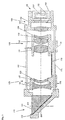
- Fig. 3 shows an electronic imaging device, (a) is a longitudinal sectional view of an embodiment f an electronic imaging device according to the present invention, and (b) is a diagram showing a cam profile in an example of a Z-cam of an electronic imaging device.
- Fig. 1 shows a cellular phone to which an embodiment of an electronic imaging device is applied, wherein (a) is a front external view showing the cellular phone, and (b) is a front view showing the cellular phone in which the electronic imaging device is mounted.
- Fig. 2 is a front view showing a usage state of the cellular phone shown in Fig. 1 .
- FIG. 4 is a development diagram showing a detailed cam profile in a Z-cam of an embodiment of an electronic imaging device according to the present invention.
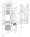
- Fig. 5 is a cross-sectional view of the electronic imaging device according to the embodiment.
- Fig. 6 is a block diagram showing a control circuit of the electronic imaging device according to the embodiment.
- the electronic imaging device 100 in the present embodiment is built into the cellular phone 10.
- the cellular phone 10 has a digital camera function as well as phone, mail, and web-browsing functions.
- the cellular phone 10 includes an imaging window 11, stroboscope light-emitting window 12, and antenna 14 of the electronic imaging device 1, as shown in Fig. 2 .
- the cellular phone 10 in the present embodiment also has a first enclosure 20 and a third enclosure 30 foldably interconnected at a hinge section 40.
- the first enclosure 20 and the second enclosure 30 are in a folded condition, and when the cellular phone 10 is in use, both enclosures 20 and 30 are in an open condition as shown in Fig. 2 .
- a liquid-crystal display screen 21 and a speaker 22 appear on the first enclosure 20
- an alphameric character input button section 31 and an operating button section 32 including a shutter button 33 appear on the second enclosure 30.
- the input button section 31 and the operating button section 32 are marked with, for example, printed or stamped characters or symbols to identify respective button functions.
- the electronic imaging device 100 when the electronic imaging device 100 is in an imaging state, regular positions of the characters and symbols marked on the cellular phone 10 to identify its button functions are in approximately the same direction as a vertical direction of the display screen. Also, a horizontal direction of the display screen and a lateral direction of the electronic imaging device 100 are approximately parallel and a long side of an effective imaging region of an imaging section is also approximately parallel to the vertical direction of the display screen. That is to say, the present embodiment employs vertical imaging as a standard display format of an acquired image with a vertical direction thereof taken as a top-down direction.
- the electronic imaging device 100 has a four-group zoom lens unit of x3 optical power, as shown in Figs. 3a and 5 .
- a first group 110 includes a prism 111 and a prism frame 112.
- a second group 120 includes two negative lenses, 121, 122, and a frame structure 123 that holds the negative lenses, 121, 122.
- a third group 130 includes two positive lenses, 131, 132, one negative lens, 133, and a frame structure 134.
- a fourth group 140 includes one positive lens, 141.
- the first group 110 and the fourth group 140 are fixed to respective lens barrels, and the second group 120 and the third group 130 are movable groups that are moved along an optical axis.
- the first group 110 is constructed only of the prism 111 that bends a beam of light at an angle of 90 degrees along a first optical axis 01.
- An entrance surface and exit surface of the prism 111 are both constructed as an optical plane not having negative/positive optical power, and a bent surface having the form of an isosceles right triangle is lined by deposition with aluminum.
- An optical axis along which the beam bent 90 degrees by the prism 111 is to be routed is taken as a second optical axis 02.
- Electronic imaging section 150 is provided behind the fourth group 140.
- the electronic imaging section 150 includes an imaging element 151 such as a CCD, a package 152 that holds the element, a hold frame 153 that holds the package 152, and an IR cutoff filter 154 that cuts off infrared light.
- the hold frame 153 is constructed to be held to a fixed frame 142, a member for holding the positive lens 141, in such a way as to be movable along the second optical axis 02. This construction allows for focus control during manufacturing processes.
- Either an absorbing type or a reflecting type is usable as the IR cutoff filter 154.
- the reflecting type is used in the present embodiment.
- the frame structure 123 of the second group 120 and the frame structure 134 of the second group 130 are held by a suspension shaft 171 and an anti-rotation member 172, both the shaft 171 and the member 172 spanning in parallel to the second optical axis 02 between the prism frame 112 of the first group 110 and the hold frame 153.
- the thus-held frame structure 123 and frame structure 134 are movable between the first group 110 and the second group 120, along the second optical axis 02.
- an inter-group spring 173 which is biased in a traction direction.
- the frame structure 123 of the second group 120 and the frame structure 134 of the second group 130 are formed with pins 124 and 135, respectively.
- the pins 124 and 135 are partly inserted into cam grooves 161 and 162, respectively, of a Z-cam 160 driven by a stepping motor 181 which constitutes a driving source 180.
- the present embodiment assumes that the stepping motor 181 has approximately 20 cogging points which the motor moves past during rotation.
- the stepping motor 181 constitutes the driving source 180 by meshing with a gear 163 provided at an end of the Z-cam via a reduction gear train 182.
- the Z-cam 160 is a cylindrical cam that rotates through about 300 degrees while it rotationally moves from a "Wide” (wide-angle) end to a "Tele” (telescopic) end.
- the Z-cam 160 has two cam grooves, 161 and 162, formed therein: one for the second group and one for the third group.
- the cam groove 161 for the second group is constructed of a zoom region 161a ranging from the wide-angle end to the telescopic end, an extended region 161b at the wide-angle side, and an extended region 161c at the telescopic side.
- the cam groove 162 for the third group is constructed of a zoom region 162a ranging from the wide-angle end to the telescopic end, an extended region 162b at the wide-angle side, and an extended region 162c at the telescopic side.
- the second group 120 reverses in a range from “Wide” to "std” (standard) and moves forward in a range from “std” to "Tele”.
- the third group 130 moves forward in a range from "Wide” to "Tele” monotonously.
- the third.group compared with the second group, moves through a long distance, and an inter-group distance between the second group and the third group becomes a minimum at "Tele.”
- the extended wide-angle region 162b and extended telescopic region 162c of the cam groove 162 for the third group are right-angled to the second optical axis and the third group does not move in a direction of the second optical axis 02.
- the cam groove 161 for the second group is progressively delivered in a direction of an object to be imaged, along the second optical axis 02.
- the second group 120 is delivered and focusing from an infinite region through a normal close-up region to a macro close-up region is thus conducted. Focusing can likewise be implemented by moving the second group 120 and the third group 130 forward through the same distance at the same time. Since this increases the moving distance required, however, focusing from the infinite side to the close-up side is accomplished in the present example by moving only the second group 120 with the third group 130 remaining fixed.
- shapes of cam grooves other than the cam grooves of the "Wide” and “Tele” ends are determined to achieve so-called pan focus so that an in-focus state can be obtained over the entire range from infinity to close-up.
- the cam groove 161 for the second group and the cam groove 162 for the third group are formed in the Z-cam 160 similarly to the Z-cam discussed above.
- focusing regions 162d, 162e, 162f are formed at wide-angle, standard, and telescopic sides, respectively, in the zoom region 162a of the cam groove 162 for the third group.
- each cam groove is disposed perpendicularly to the optical axis and the third group 130 does not move in the direction of the second optical axis 02. Accordingly, a zoom ratio between the lenses becomes constant.
- the zoom region of the second-group cam groove 161 that is associated with the focusing regions 162d, 162e, 162f the second group 120 is moved along the optical axis 02 and this movement makes focusing possible.
- the present embodiment also assumes that the focusing regions 162d, 162e, 162f has small force control width, compared with the focusing regions provided at the wide-angle end and the telescopic end. Additionally in the present embodiment, infinity is assigned to entrance ends of both the extended wide-angle region and extended telescopic region provided at the wide-angle end and the telescopic end. For this reason, a moving-direction change point 161d is formed in the zoom region of the cam groove 161 for the second group. In addition, the present embodiment assumes that the focusing regions in the zoom region are formed so as not to be included in the inflection point (change point) 161d. Smooth focusing is thus possible.
- Fig. 6 is a block diagram showing the control circuit of the electronic imaging device according to the present embodiment.
- a zoom switch 211 and a release switch 221 (in Fig. 2 , the shutter button 33), both arranged on the cellular phone 10, are connected to a camera controller 210.
- the control circuit uses a zoom motor controller 214 to drive a zoom motor 215, the stepping motor 181 for rotationally driving the Z-cam 160.
- a zoom position encoder 213 that acquires zoom position information, and a zoom-resetting encoder 216 that initializes a zoom position are connected to the zoom motor controller 214.
- the camera controller 210 has an AF controller 221 that undertakes auto-focusing control, and an AF motor 223 is driven under control of an AF motor controller 222 connected to the AF controller 221.
- An AF position encoder 224 is also connected to the AF motor controller 222.
- the stepping motor 181 functions as an AF motor and the above-mentioned zoom motor 215. That is to say, as shown in Fig. 4 , in the present embodiment, the electronic imaging device 100 maintains lenses in a pan-focus state while the target object is in a range from a maximum wide-angle region to a maximum telescopic region, and conducts focusing in the extended regions 161a, 161b, 162a, 162b of the cam grooves 161, 162. Accordingly, the stepping motor operates as the zoom motor in the range from the maximum wide-angle region to the maximum telescopic region, and operates as the AF motor in the extended regions 161a, 161b, 162a, 162b.
- the cellular phone 10 further has a macro mode input element (a push button on the cellular phone 10) and a macro mode controller 226 in order to enable imaging in a macro mode.
- a macro mode input element a push button on the cellular phone 10
- a macro mode controller 226 in order to enable imaging in a macro mode.
- the control circuit has a CCD (charge-coupled device) 237 (in Fig. 5 , element 151) as an imaging element.
- a CCD charge-coupled device
- One type of image signal from the CCD 237 is sent to a still image processor 234 via an A/D converter 236 and then stored into a memory 231 via a still image compressor 232.
- another type of image signal from the CCD 237 is sent to a video image processor 235 via the A/D converter 236 and then stored into the memory 231 via a video image compressor 233.
- the CCD 237 is automatically exposure-controlled by an AE controller 225.
- the cellular phone 10 has a display element 239 (in Fig. 2 , liquid-crystal display 21) that makes a color display of a still image or a video image under display control of a display controller 238.
- a display element 239 in Fig. 2 , liquid-crystal display 21
- a stroboscope light-emitting section 245 (in Fig. 1 , stroboscope light-emitting window 12 for emitting light) is provided for target object illumination.
- a stroboscope charger 242 and a charge voltage detector 243 are connected to the stroboscope light-emitting section 245, and charging is controlled by the stroboscope charger 242 and the charge voltage detector 243.
- the stroboscope charge controller 241 oscillates in response to an external pulse signal and generates a high voltage
- the stroboscope light-emitting section 245 has a stroboscope light-emission controller 244, which controls the stroboscope light-emitting section 245 to emit an appropriate amount of light.
- the electronic imaging device 100 in the present embodiment has a total controller 250 that controls the entire cellular phone 10, and the total controller 250 has a transmitting/receiving controller 252, a transmitter/receiver 253, and an antenna 254, which are phone functions.
- the total controller 250 also has push buttons and other controls, a microphone 255 (in Fig. 2 , element 34), and a speaker 256 (in Fig. 2 , element 22).
- the electronic imaging device 100 has an electric power controller 240, which conducts efficient power consumption control of a secondary cell (not shown) of a limited capacity of the cellular phone 10 as a whole.
- the electric power controller 240 controls supply of electric power from the secondary cell to various sections.
- These sections refer to: a driver that includes the stepping motor 181 adapted to move the above-described lens groups for a magnification change; an imaging section (such as CCD 237) that converts an image of the target object into an electrical signal; a display section including the display element 239 that makes various displays, inclusive of the image acquired by the imaging section; and a communications section adapted for purposes such as conversations, mail/data transfer, and Internet connection.
- the required relationship in the electric power controller 240 can include prohibiting the supply of electric power to the communications section during the supply of electric power to the driver and the imaging section, or prohibiting the supply of electric power to the driver and the imaging section during the supply of electric power to the communications section.
- the electric power controller 240 can have at least one of four functions intended for a speed change of the driver, a frame rate change of the imaging section, a display brightness change of the display section, and a communications rate change of the communications section.
- the electric power controller 240 can also change either a frequency or duty ratio of the pulse signal input to the above charger.
- the electric power controller 240 can limit or prohibit the supply of electric power to the above charger.
- the electric power controller 240 can calculate a suppliable amount of electric power according to the particular residual amount of charge in the secondary cell, and supply electric power to the imaging section, the display section, and/or the communications section. Even during the supply of electric power to these sections, the electric power controller 240 can also supply the power to the charger if the secondary cell has margins on its capacity. In that case, while controlling the pulse signal, the electric power controller 240 can control a total supply rate of the power so that this supply rate does not exceed an energy supply capability of the secondary cell.
- the electric power controller 240 can lower a frequency (rate) at which the stroboscope light-emitting section 245 can emit light.
- the present embodiment assumes that the required relationship in the electric power controller 240 can be changed by a user.
- the reflective optical system can be reduced in depth and when the electronic imaging device is mounted in an electronic appliance such as a cellular phone, the electric appliance can be minimized in thickness.
- the reflective optical section closest to the target object does not have any related lenses, it is possible to easily conduct optical axis alignment and to reduce the electronic imaging device in thickness.
- electric power consumption in the electronic imaging device can be minimized and this, in turn, minimizes energy consumption in the secondary cell of the cellular phone in which the electronic imaging device is mounted.
- Fig. 7 is a cross-sectional view of the electronic imaging device 200 according to the present (second) embodiment.
- the present embodiment has the same basic construction as that of the electronic imaging device 100 according to the first embodiment described above.
- the same reference number or symbol is assigned to the same member as that of the above electronic imaging device 100, and description of these members is omitted.
- a reflective optical system 190 is disposed at a stage posterior to a fourth group 140
- a third optical axis 03 is set at right angles to a second optical axis 02
- an imaging system 195 is disposed on the third optical axis 03.
- the reflective optical system 190 includes a rectangular prism 191 and a prism frame 192.
- An entrance surface and exit surface of the rectangular prism 191 are both constructed as an optical plane not having negative/positive optical power, and a bent surface having the form of an isosceles right triangle is lined by deposition with aluminum.
- the imaging system 150 according to the present embodiment includes an imaging element 196, a package 197, a hold frame 198, and an IR cutoff filter 199.
- providing reflective optical elements makes it possible to prevent an increase in the thickness of the electronic imaging device due to package thickness of the imaging element, and thus to construct the electronic imaging device as a thinner one.
- Fig. 8 shows an electronic imaging device 300
- (a) is a longitudinal sectional view of a present (third) embodiment of an electronic imaging device according to the present invention
- (b) is a diagram showing a cam profile in an example of a Z-cam of an electronic imaging device.
- the electronic imaging device 300 according to the present embodiment is modified in that the positions of the electronic imaging device 100 and driving source 360 in the first embodiment are both changed to the side of the first group 110.
- the driving source 360 includes a stepping motor 361 and a gear train 362 and transmits driving force to the gear 163 of the Z-cam 160.
- the electronic imaging device 300 can be reduced in overall length.
- a Z-cam 410 differs from the Z-cams of the above embodiments in terms of cam profile.
- Fig. 9 is a diagram showing the cam profile of the Z-cam in the present modification of the electronic imaging device according to the associated embodiment.
- a cam groove 411 for a second group is constructed of a zoom region 411a ranging from a wide-angle end to a telescopic end, an extended region 411b at the wide-angle side, and an extended region 411c at the telescopic side.
- a cam groove 412 for a third group is constructed of a zoom region 412a ranging from the wide-angle end to the telescopic end, an extended region 412b at the wide-angle side, and an extended region 412c at the telescopic side.
- the extended wide-angle region 412b of the cam groove 412 for the third group is right-angled to a second optical axis and the third group does not move in a direction of the second optical axis 02.
- the cam groove 411 for the second group is progressively delivered in a direction of an object to be imaged, along the second optical axis 02.
- the second group 120 is delivered and focusing from a pan-focus region to a macro close-up region is thus conducted.
- the extended telescopic region 412c of the cam groove 412 for the third group is right-angled to the second optical axis and the third group does not move in the direction of the second optical axis 02.
- the cam groove 411 for the second group is progressively drawn in towards an imaging element along the second optical axis 02.
- the second group 120 is drawn in and focusing from the pan-focus region to a Telescopic view region is thus conducted.
- shapes of cam grooves other than the cam grooves of the "Wide” and “Tele” ends are determined to achieve so-called pan focus so that an in-focus state can be obtained over the entire range from infinity to close-up.
- a Z-cam 420 differs from the Z-cams of the above embodiments in terms of cam profile.
- Fig. 10 is a diagram showing the cam profile of the Z-cam in the present example of the electronic imaging device according to the associated embodiment.
- a cam groove 421 for a second group is constructed of a zoom region 421a ranging from a wide-angle end to a telescopic end, an extended region 421b at the wide-angle side, and an extended region 421c at the telescopic side.
- a cam groove 422 for a third group is constructed of a zoom region 422a ranging from the wide-angle end to the telescopic end, an extended region 422b at the wide-angle side, and an extended region 422c at the telescopic side.
- the extended wide-angle region 422b of the cam groove 422 for the third group is right-angled to a second optical axis and the third group does not move in a direction of the second optical axis 02.
- the cam groove 421 for the second group is progressively drawn in towards an imaging element along the second optical axis 02.
- the second group 120 is drawn in and focusing from a "Wide” macro region through a "Wide” close-up region to "Wide” infinity ( ⁇ ) is thus conducted.
- the extended telescopic region 422c of the cam groove 422 for the third group is right-angled to the second optical axis and the third group does not move in the direction of the second optical axis 02.
- the cam groove 421 for the second group is progressively drawn in towards an object to be imaged, along the second optical axis 02.
- shapes of cam grooves other than the cam grooves of the "Wide” and “Tele” ends are determined to achieve so-called pan focus so that an in-focus state can be obtained over the entire range from infinity to close-up.
- a Z-cam 550 differs from the Z-cams of the above embodiments in terms of cam profile.
- Fig. 11 is a diagram showing the cam profile of the Z-cam in an example of an electronic imaging device.
- a cam groove 551 for a second group is constructed of a zoom region 551a ranging from a wide-angle end to a telescopic end, an extended wide-angle region 551b, and an extended telescopic region 551c.
- the three regions are formed in approximately rectilinear form, and respective widths in a direction of an optical axis are approximately the same as width of a pin 124 associated with the second group 120.
- a cam groove 552 for a third group is constructed of a zoom region 552a ranging from the wide-angle end to the telescopic end, an extended wide-angle region 552b, and an extended telescopic region 552c.
- these three regions are formed so that respective widths in the direction of the optical axis are approximately the same as width of a pin 135 associated with the third group 130, and so that the widths of the three regions are greater than the width of the zoom region 552a in the direction of the optical axis.
- the third group 130 has suitable frictional force and is held so that once positioned, the third group 130 will move only when it comes into contact with the cam groove 552. This can be achieved by, for example, generating great friction between a suspension shaft 171 and a frame structure 134 or biasing the frame structure 134 perpendicularly with respect to the optical axis.
- the pin 135 disposed in the cam groove 552 will not move, even when a pin 124 engaged with the cam groove 551 is moved by rotationally moving the Z-cam 550 from position "i" to position "ii” shown in Fig. 11 . In this range, therefore, the first group 110 can be moved for focusing.
- focusing in the extended telescopic region and the extended wide-angle region can be conducted similarly to each embodiment or example described above.
- the cam groove 552 can be constructed so that as denoted by reference number 553 in Fig. 11 , the dimension of the cam groove 552 in the direction of the optical axis spreads towards the telescopic side. According to the present embodiment, a moving distance of the second group 120 can be increased during focusing in the zoom region.
- Fig. 12 is a diagram showing schematically the electronic imaging device according to the present example.
- Fig. 13 is a diagram showing an installation state of a Z-cam of the electronic imaging device shown in Fig. 12 .
- Fig. 14 is a diagram showing a cam profile of the Z-cam in the electronic imaging device of Fig. 12 .
- the electronic imaging device 600 makes the Z-cam 650 movable in parallel with respect to an optical axis, and drives the Z-cam as an inverse cam.
- cam grooves 651 and 652 for moving a second group and a third group, respectively, a cam groove 653 for moving the Z-cam 650, and a carriage 623 that engages with the cam groove 653 are provided in the present example.
- the electronic imaging device 600 includes the Z-cam 650, the second group 620, the third group 630, and frame structures 621 and 631 that engage with the cam grooves 651 and 652, respectively, of the Z-cam 650.
- a stepping motor 641 in a driving system 640 of the present example has a screw rod 642 and a nut member 643 threaded onto the screw rod 642, and drives the carriage 623. A movement of the carriage 623 rotates the Z-cam 650.
- the second group 620 and the third group 630 are then driven for zooming.
- the cam grooves 651 and 652 can, as shown in Fig. 14 , be constructed similarly to the cam grooves of each embodiment or example described above.
- a first group 610, a fourth group 640, an imaging element 650, and a sliding shaft 654 are fixed to a device body 661 of the electronic imaging device 600.
- the second group 620, the third group 630, and the driving system 640 are constructed as a whole so as to irrotationally movable in a direction of an optical axis (as indicated by arrow A in Figs. 12 , 13 ).
- the Z-cam 650 is rotatably and slidably installed on the sliding shaft 654 provided in parallel to an optical axis 02 of the device body 661.
- focusing is accomplished by moving the Z-cam 650, the second group 620, the third group 630, and the driving system 640, along the sliding shaft 654 via an element not shown, for example, a stepping motor or the like.
- the zoom lens mechanism of the electronic imaging device is of simple focusing construction, it is possible to obtain an electronic imaging device that is compact and high in zoom ratio and in image quality.
- the optical system is constructed so as to ensure pan focus during zooming, the image to be acquired is free from blurring, even during zooming towards the telescopic side and the wide-angle side.
- the optical system is constructed so that infinite, close-up, and macro focusing operations can be performed at the telescopic end and/or the wide-angle end, it is possible to obtain an in-focus sharp image at the focusing end, whether it be the telescopic end or the wide-angle end.
- this optical system can be reduced in depth and when the electronic imaging device according to the present invention is mounted in an electronic appliance such as a cellular phone, the electric appliance can be minimized in thickness.
- the reflective optics closest to the target object does not have any related lenses, it is possible to easily conduct optical axis alignment and to reduce the electronic imaging device in thickness.
- the electronic imaging device has reflective optics at the imaging element side, an increase in the thickness of the electronic imaging device due to package thickness of the imaging element can be prevented, which makes the electronic imaging device constructible as an even thinner one.
- the electronic imaging device can be dimensionally reduced since refractive optics is dimensionally limited to the minimum required.
- the electronic imaging device when the electronic imaging device is of the construction intended for an electronic appliance in which the imaging device is to be used in a vertically long position, the electronic imaging device can be disposed in a transverse direction and is particularly suitable for use in a cellular phone when images are acquired with the cellular phone held in a vertically long position.
- the electronic imaging device since the electronic imaging device includes an electric power controller, it is possible to minimize the power consumed in the electronic imaging device, and thus to minimize the energy consumed in a secondary cell of an electronic appliance in which the electronic imaging device is mounted.
- the present invention can be used for PDAs, compact digital cameras, and other electronic appliances, as well as for cellular phones.
Landscapes
- Physics & Mathematics (AREA)
- General Physics & Mathematics (AREA)
- Optics & Photonics (AREA)
- Engineering & Computer Science (AREA)
- General Engineering & Computer Science (AREA)
- Studio Devices (AREA)
- Lens Barrels (AREA)
- Transforming Light Signals Into Electric Signals (AREA)
- Lenses (AREA)
- Details Of Cameras Including Film Mechanisms (AREA)
- Indication In Cameras, And Counting Of Exposures (AREA)
- Stroboscope Apparatuses (AREA)
- Camera Bodies And Camera Details Or Accessories (AREA)
- Structure And Mechanism Of Cameras (AREA)
Claims (8)
- Dispositif électronique d'imagerie (100) comprenant :un premier groupe de lentilles (110) positionné dans la proximité la plus proche d'un objet dont une image doit être formée, parmi tous les éléments optiques principaux du dispositif d'imagerie ;un deuxième groupe de lentilles (120) qui de déplace pour modifier un grossissement d'une image à acquérir ;un troisième groupe de lentilles (130) dont le déplacement pour une autre modification de grossissement de l'image à acquérir diffère du déplacement du deuxième groupe de lentilles (120) ; etdes moyens de déplacement de groupe de lentilles équipés de moyens d'entraînement (180) et de rainures de came (161, 162) pour déplacer le deuxième groupe de lentilles (120) et le troisième groupe de lentilles (130) sur des distances prédéfinies respectives le long d'un axe optique en fonction de la quantité particulière d'entraînement par les moyens d'entraînement (180), les moyens de déplacement de groupe de lentilles étant adaptés pour modifier un grossissement variable total du deuxième groupe de lentilles (120) et du troisième groupe de lentilles (130) ; caractérisé en ce queles rainures de came (161, 162) dans les moyens de déplacement de groupe de lentilles sont formées de manière à comprendre, dans une région de grossissement (161a, 162a) d'une extrémité de grand angle à une extrémité télescopique, une région de mise au point (162d, 162e, 162f) dans laquelle un foyer peut être déplacé en commandant un déplacement total à la fois des deuxième et troisième groupes de lentilles (120, 130), le troisième groupe de lentilles (130) étant fixe dans une direction de l'axe optique dans la région dans laquelle le deuxième groupe de lentilles (120) et le troisième groupe de lentilles (130) entrent dans un état de mise au point panoramique ;les moyens de déplacement de groupe de lentilles étant adaptés pour déplacer en va-et-vient le deuxième groupe de lentilles (120) le long d'un axe optique dans la région de grossissement (161a) ;dans lequel la région de mise au point (162d, 162e, 162f) dans la région de grossissement (161a, 162a) est déterminée de manière à ne pas comprendre une section d'un point de changement d'une direction de déplacement du deuxième groupe de lentilles (120).
- Dispositif électronique d'imagerie selon la revendication 1, dans lequel le premier groupe de lentilles (110) comprend des moyens optiques de réflexion adaptés pour réfléchir un faisceau de lumière le long d'un trajet optique à partir de l'objet cible.
- Dispositif électronique d'imagerie selon la revendication 1 ou 2, comprenant en outre un élément électronique d'imagerie (151).
- Dispositif électronique d'imagerie selon la revendication 3, comprenant en outre à : des moyens de commande de mise au point adaptés pour recevoir un signal de l'élément électronique d'imagerie (151) et effectuer une commande de mise au point des moyens d'entraînement.
- Dispositif électronique d'imagerie selon l'une quelconque des revendications 1 à 4, comprenant en outre :des moyens de sélection de mode adaptés pour faire en sorte qu'un mode de mise au point panoramique ou un mode de mise au point automatique soit sélectionnable ; dans lequel,lorsque le mode de mise au point panoramique est sélectionné en utilisant les moyens de sélection de mode, les moyens de commande de mise au point commandent l'entraînement des moyens de déplacement de groupe de lentilles et provoquent l'agencement des groupes de lentilles (120, 130) dans l'état de grand angle final et dans l'état télescopique final à une position de mise au point panoramique dans la région de came étendue.
- Dispositif électronique d'imagerie selon l'une quelconque des revendications 1 à 5,
dans lequel les moyens de déplacement de groupe de lentilles comprennent un contrôleur de mise au point de région de macro grand angle dans la région de came étendue formée à une position antérieur à l'extrémité de grand angle, et/ou un contrôleur de mise au point de macro télescopique dans la région de came étendue formée à une position antérieure à l'extrémité télescopique. - Dispositif électronique d'imagerie selon l'une quelconque des revendications 1 à 6, dans lequel, lorsqu'elle est vue à partir de l'extrémité de grand angle ou de l'extrémité télescopique, la région de came étendue des moyens de déplacement de groupe de lentilles est formée à une position infinie, à une position de gros plan d'imagerie normal, et à une position de région de macro, dans cet ordre.
- Dispositif électronique d'imagerie selon l'une quelconque des revendications 1 à 7, dans lequel
les rainures de came dans les moyens de déplacement de groupe de lentilles comprennent une première rainure de came (161) qui détermine une distance de déplacement du deuxième groupe de lentilles (120), et une deuxième rainure de came (162) qui détermine une distance de déplacement du troisième groupe de lentilles (130) ;
la première rainure de came (161) est formée avec une région de came étendue d'extrémité de grand angle dans laquelle une région de macro d'extrémité de grand angle, une région de gros plan normal d'extrémité de grand angle, et une région infinie d'extrémité de grand angle sont agencées dans cet ordre vers une région de came, la première rainure de came étant en outre formée avec une région de grossissement variable et une région de came étendue d'extrémité télescopique dans laquelle une région infinie d'extrémité télescopique, une région de gros plan d'imagerie normal d'extrémité télescopique, et une région de macro d'extrémité télescopique sont agencées dans cet ordre à partir de la région de came ; et
la deuxième rainure de came (162) est réalisée pour avoir une région de came étendue de grand angle comprenant une région dans laquelle le troisième groupe de lentilles ne se déplace pas dans une direction d'un axe optique à une extrémité de grand angle, une région de grossissement variable, et une région de came étendue comprenant une région dans laquelle le troisième groupe de lentilles ne se déplace pas dans la direction de l'axe optique à une extrémité télescopique.
Applications Claiming Priority (1)
| Application Number | Priority Date | Filing Date | Title |
|---|---|---|---|
| PCT/JP2004/010303 WO2006008805A1 (fr) | 2004-07-20 | 2004-07-20 | Dispositif électronique d’imagerie |
Publications (3)
| Publication Number | Publication Date |
|---|---|
| EP1780567A1 EP1780567A1 (fr) | 2007-05-02 |
| EP1780567A4 EP1780567A4 (fr) | 2009-12-16 |
| EP1780567B1 true EP1780567B1 (fr) | 2011-09-14 |
Family
ID=35784941
Family Applications (1)
| Application Number | Title | Priority Date | Filing Date |
|---|---|---|---|
| EP04770814A Not-in-force EP1780567B1 (fr) | 2004-07-20 | 2004-07-20 | Dispositif électronique d'imagerie |
Country Status (4)
| Country | Link |
|---|---|
| EP (1) | EP1780567B1 (fr) |
| JP (1) | JP4894041B2 (fr) |
| AT (1) | ATE524760T1 (fr) |
| WO (1) | WO2006008805A1 (fr) |
Families Citing this family (43)
| Publication number | Priority date | Publication date | Assignee | Title |
|---|---|---|---|---|
| JP5487780B2 (ja) * | 2009-07-30 | 2014-05-07 | 株式会社ニコン | レンズ鏡筒及びカメラ |
| JP5656537B2 (ja) * | 2010-10-01 | 2015-01-21 | 日東光学株式会社 | ズームレンズ駆動装置 |
| JP5827048B2 (ja) * | 2011-07-04 | 2015-12-02 | 日東光学株式会社 | ズームレンズ駆動装置、デジタルカメラ |
| CN113259565B (zh) | 2012-11-28 | 2023-05-19 | 核心光电有限公司 | 多孔径成像系统 |
| CN109040553B (zh) | 2013-06-13 | 2021-04-13 | 核心光电有限公司 | 双孔径变焦数字摄影机 |
| KR101757101B1 (ko) | 2013-07-04 | 2017-07-12 | 코어포토닉스 리미티드 | 소형 망원 렌즈 조립체 |
| CN105917641B (zh) | 2013-08-01 | 2018-10-19 | 核心光电有限公司 | 具有自动聚焦的纤薄多孔径成像系统及其使用方法 |
| US9392188B2 (en) | 2014-08-10 | 2016-07-12 | Corephotonics Ltd. | Zoom dual-aperture camera with folded lens |
| CN107209404B (zh) | 2015-01-03 | 2021-01-15 | 核心光电有限公司 | 微型长焦镜头模块和使用该镜头模块的相机 |
| US10036895B2 (en) | 2015-05-28 | 2018-07-31 | Corephotonics Ltd. | Bi-directional stiffness for optical image stabilization in a dual-aperture digital camera |
| KR102263924B1 (ko) | 2015-08-13 | 2021-06-11 | 코어포토닉스 리미티드 | 비디오 지원 및 스위칭/비스위칭 동적 제어 기능이 있는 듀얼-애퍼처 줌 카메라 |
| CN109889708B (zh) | 2015-12-29 | 2021-07-06 | 核心光电有限公司 | 具有自动可调节长焦视场的双孔径变焦数字摄影机 |
| JP6843589B2 (ja) * | 2016-03-09 | 2021-03-17 | キヤノン株式会社 | レンズ鏡筒、及び撮像装置 |
| EP3292685B1 (fr) | 2016-05-30 | 2019-06-05 | Corephotonics Ltd. | Moteur à bobine acoustique guidé par une bille rotative |
| EP4270978A3 (fr) | 2016-06-19 | 2024-02-14 | Corephotonics Ltd. | Synchronisation de trame dans un système de caméra à double ouverture |
| US10706518B2 (en) | 2016-07-07 | 2020-07-07 | Corephotonics Ltd. | Dual camera system with improved video smooth transition by image blending |
| EP4224233A1 (fr) | 2016-07-07 | 2023-08-09 | Corephotonics Ltd. | Moteur à bobine acoustique linéaire guidé par bille pour optique pliée |
| EP3563193B1 (fr) | 2016-12-28 | 2021-03-31 | Corephotonics Ltd. | Structure de caméra pliée ayant une plage étendue de balayage avec des éléments de repliement de lumière |
| JP7057364B2 (ja) | 2017-01-12 | 2022-04-19 | コアフォトニクス リミテッド | コンパクト屈曲式カメラ |
| EP4357832A3 (fr) | 2017-03-15 | 2024-05-29 | Corephotonics Ltd. | Caméra à plage de balayage panoramique |
| US10904512B2 (en) | 2017-09-06 | 2021-01-26 | Corephotonics Ltd. | Combined stereoscopic and phase detection depth mapping in a dual aperture camera |
| US10951834B2 (en) | 2017-10-03 | 2021-03-16 | Corephotonics Ltd. | Synthetically enlarged camera aperture |
| EP4250695A3 (fr) * | 2017-11-23 | 2023-11-22 | Corephotonics Ltd. | Structure de caméra pliée compacte |
| WO2019150188A1 (fr) | 2018-02-05 | 2019-08-08 | Corephotonics Ltd. | Pénalité de hauteur réduite pour appareil photo plié |
| US10694168B2 (en) | 2018-04-22 | 2020-06-23 | Corephotonics Ltd. | System and method for mitigating or preventing eye damage from structured light IR/NIR projector systems |
| EP4303653A1 (fr) | 2018-04-23 | 2024-01-10 | Corephotonics Ltd. | Élément de pliage de trajet optique avec une plage de rotation étendue à deux degrés de liberté |
| US11019242B2 (en) | 2018-06-14 | 2021-05-25 | Guangdong Oppo Mobile Telecommunications Corp., Ltd. | Camera assembly and electronic device using the same, both having a decorative member mounted on a shell and comprising a decorative ring and a flange |
| CN108449540B (zh) | 2018-06-15 | 2020-07-10 | Oppo广东移动通信有限公司 | 摄像头模组、摄像头组件和电子装置 |
| EP3652728B1 (fr) | 2018-08-04 | 2023-06-07 | Corephotonics Ltd. | Caméra d'en haut de système d'information d'affichage continu commutable |
| WO2020039302A1 (fr) | 2018-08-22 | 2020-02-27 | Corephotonics Ltd. | Caméra pliée à zoom à deux états |
| WO2020144528A1 (fr) | 2019-01-07 | 2020-07-16 | Corephotonics Ltd. | Mécanisme de rotation à joint coulissant |
| CN113891059B (zh) | 2019-03-09 | 2024-02-13 | 核心光电有限公司 | 对双摄像机进行立体校准的方法 |
| KR20240027858A (ko) | 2019-07-31 | 2024-03-04 | 코어포토닉스 리미티드 | 카메라 패닝 또는 모션에서 배경 블러링을 생성하는 시스템 및 방법 |
| US11659135B2 (en) | 2019-10-30 | 2023-05-23 | Corephotonics Ltd. | Slow or fast motion video using depth information |
| US11949976B2 (en) | 2019-12-09 | 2024-04-02 | Corephotonics Ltd. | Systems and methods for obtaining a smart panoramic image |
| KR20220058593A (ko) | 2019-12-09 | 2022-05-09 | 코어포토닉스 리미티드 | 스마트한 파노라마 이미지를 획득하기 위한 시스템 및 방법 |
| EP4058978A4 (fr) | 2020-05-17 | 2022-12-28 | Corephotonics Ltd. | Assemblage d'images en présence d'une image de référence à champ de vision complet |
| WO2021245488A1 (fr) | 2020-05-30 | 2021-12-09 | Corephotonics Ltd. | Systèmes et procédés pour obtenir une super macro-image |
| EP4202521A1 (fr) | 2020-07-15 | 2023-06-28 | Corephotonics Ltd. | Correction d'aberrations de point de vue dans une caméra à balayage plié |
| US11637977B2 (en) | 2020-07-15 | 2023-04-25 | Corephotonics Ltd. | Image sensors and sensing methods to obtain time-of-flight and phase detection information |
| CN214474266U (zh) * | 2020-07-24 | 2021-10-22 | 台湾东电化股份有限公司 | 光学系统 |
| EP4065934A4 (fr) | 2020-07-31 | 2023-07-26 | Corephotonics Ltd. | Géométrie d'aimant de capteur à effet hall de détection de position linéaire de grande course |
| CN116679419A (zh) | 2020-08-12 | 2023-09-01 | 核心光电有限公司 | 用于光学防抖的装置和方法 |
Family Cites Families (8)
| Publication number | Priority date | Publication date | Assignee | Title |
|---|---|---|---|---|
| US4881799A (en) * | 1987-04-20 | 1989-11-21 | Ricoh Company, Ltd. | Varifocal lens device |
| US4831093A (en) | 1988-08-26 | 1989-05-16 | E. I. Du Pont De Nemours And Company | Polymerization process for methyl methacrylate with improved activator system |
| JP2929480B2 (ja) | 1991-04-16 | 1999-08-03 | オリンパス光学工業株式会社 | ズームカメラ |
| JPH08297237A (ja) * | 1995-04-27 | 1996-11-12 | Nikon Corp | レンズ鏡筒 |
| JPH11174311A (ja) * | 1997-12-17 | 1999-07-02 | Canon Inc | 光学系駆動装置およびこれを備えた光学機器 |
| JP3530878B2 (ja) * | 1999-01-20 | 2004-05-24 | ミノルタ株式会社 | ズームカメラ |
| JP2003043354A (ja) * | 2001-05-14 | 2003-02-13 | Olympus Optical Co Ltd | 電子撮像装置 |
| JP5226166B2 (ja) | 2001-09-21 | 2013-07-03 | オリンパス株式会社 | 折り曲げ結像光学系 |
-
2004
- 2004-07-20 JP JP2006527697A patent/JP4894041B2/ja not_active Expired - Fee Related
- 2004-07-20 AT AT04770814T patent/ATE524760T1/de not_active IP Right Cessation
- 2004-07-20 WO PCT/JP2004/010303 patent/WO2006008805A1/fr active Application Filing
- 2004-07-20 EP EP04770814A patent/EP1780567B1/fr not_active Not-in-force
Also Published As
| Publication number | Publication date |
|---|---|
| JPWO2006008805A1 (ja) | 2008-07-31 |
| EP1780567A1 (fr) | 2007-05-02 |
| WO2006008805A1 (fr) | 2006-01-26 |
| JP4894041B2 (ja) | 2012-03-07 |
| ATE524760T1 (de) | 2011-09-15 |
| EP1780567A4 (fr) | 2009-12-16 |
Similar Documents
| Publication | Publication Date | Title |
|---|---|---|
| EP1780567B1 (fr) | Dispositif électronique d'imagerie | |
| KR102225727B1 (ko) | 소형의 접이식 카메라의 롤 보정에 의한 자동 초점 및 광학식 손떨림 방지 | |
| KR101278239B1 (ko) | 듀얼 렌즈 광학계 및 이를 구비하는 듀얼 렌즈 카메라 | |
| US7532408B2 (en) | Variable magnification optical system and image-taking apparatus | |
| JP2000275518A (ja) | ズームレンズ系 | |
| US7420755B2 (en) | Lens driving device | |
| US7116488B2 (en) | Optical system for zoom-camera | |
| KR20200072256A (ko) | 렌즈 어셈블리 및 이를 포함하는 카메라 모듈 | |
| CN115993751A (zh) | 相机模块与电子装置 | |
| CN114157784A (zh) | 一种摄像模组及终端设备 | |
| US20100086291A1 (en) | Camera module and driving method thereof | |
| EP1530072A1 (fr) | Objectif de zoom avec convertisseur insérable de foyer et système d'imagerie | |
| CN114185166A (zh) | 一种潜望式摄像模组及终端设备 | |
| CN115943344A (zh) | 相机模块 | |
| JP2003262780A (ja) | ズーム光学系 | |
| US7532418B2 (en) | Lens barrel and image pickup apparatus | |
| CN117555191A (zh) | 遮光结构与成像镜头模块 | |
| CN102566204A (zh) | 有光照射功能的变焦透镜驱动装置、相机及移动终端装置 | |
| TWI356628B (fr) | ||
| JP2009015028A (ja) | 変倍光学系、撮影レンズユニットおよびカメラ | |
| CN211263930U (zh) | 潜望式镜头 | |
| CN115128795B (zh) | 镜头组件及电子设备 | |
| CN113556444B (zh) | 潜望式摄像模组、多摄摄像模组和摄像模组的驱动方法 | |
| KR100782477B1 (ko) | 간단한 줌렌즈 광학계 | |
| JP4018457B2 (ja) | 撮像装置及びその制御方法 |
Legal Events
| Date | Code | Title | Description |
|---|---|---|---|
| PUAI | Public reference made under article 153(3) epc to a published international application that has entered the european phase |
Free format text: ORIGINAL CODE: 0009012 |
|
| 17P | Request for examination filed |
Effective date: 20070220 |
|
| AK | Designated contracting states |
Kind code of ref document: A1 Designated state(s): AT BE BG CH CY CZ DE DK EE ES FI FR GB GR HU IE IT LI LU MC NL PL PT RO SE SI SK TR |
|
| RIN1 | Information on inventor provided before grant (corrected) |
Inventor name: NAKAMURA, HIROAKI,C/O FIVE DIMENSION CO., LTD |
|
| DAX | Request for extension of the european patent (deleted) | ||
| A4 | Supplementary search report drawn up and despatched |
Effective date: 20091116 |
|
| 17Q | First examination report despatched |
Effective date: 20100726 |
|
| REG | Reference to a national code |
Ref country code: DE Ref legal event code: R079 Ref document number: 602004034353 Country of ref document: DE Free format text: PREVIOUS MAIN CLASS: G02B0007040000 Ipc: G02B0007100000 |
|
| GRAP | Despatch of communication of intention to grant a patent |
Free format text: ORIGINAL CODE: EPIDOSNIGR1 |
|
| RIC1 | Information provided on ipc code assigned before grant |
Ipc: G02B 7/10 20060101AFI20110309BHEP Ipc: G02B 13/00 20060101ALI20110309BHEP |
|
| R17C | First examination report despatched (corrected) |
Effective date: 20100726 |
|
| GRAS | Grant fee paid |
Free format text: ORIGINAL CODE: EPIDOSNIGR3 |
|
| GRAA | (expected) grant |
Free format text: ORIGINAL CODE: 0009210 |
|
| AK | Designated contracting states |
Kind code of ref document: B1 Designated state(s): AT BE BG CH CY CZ DE DK EE ES FI FR GB GR HU IE IT LI LU MC NL PL PT RO SE SI SK TR |
|
| REG | Reference to a national code |
Ref country code: GB Ref legal event code: FG4D |
|
| REG | Reference to a national code |
Ref country code: CH Ref legal event code: EP |
|
| REG | Reference to a national code |
Ref country code: IE Ref legal event code: FG4D |
|
| REG | Reference to a national code |
Ref country code: DE Ref legal event code: R096 Ref document number: 602004034353 Country of ref document: DE Effective date: 20111110 |
|
| REG | Reference to a national code |
Ref country code: NL Ref legal event code: T3 |
|
| PG25 | Lapsed in a contracting state [announced via postgrant information from national office to epo] |
Ref country code: FI Free format text: LAPSE BECAUSE OF FAILURE TO SUBMIT A TRANSLATION OF THE DESCRIPTION OR TO PAY THE FEE WITHIN THE PRESCRIBED TIME-LIMIT Effective date: 20110914 Ref country code: SE Free format text: LAPSE BECAUSE OF FAILURE TO SUBMIT A TRANSLATION OF THE DESCRIPTION OR TO PAY THE FEE WITHIN THE PRESCRIBED TIME-LIMIT Effective date: 20110914 |
|
| PG25 | Lapsed in a contracting state [announced via postgrant information from national office to epo] |
Ref country code: CY Free format text: LAPSE BECAUSE OF FAILURE TO SUBMIT A TRANSLATION OF THE DESCRIPTION OR TO PAY THE FEE WITHIN THE PRESCRIBED TIME-LIMIT Effective date: 20110914 Ref country code: SI Free format text: LAPSE BECAUSE OF FAILURE TO SUBMIT A TRANSLATION OF THE DESCRIPTION OR TO PAY THE FEE WITHIN THE PRESCRIBED TIME-LIMIT Effective date: 20110914 Ref country code: GR Free format text: LAPSE BECAUSE OF FAILURE TO SUBMIT A TRANSLATION OF THE DESCRIPTION OR TO PAY THE FEE WITHIN THE PRESCRIBED TIME-LIMIT Effective date: 20111215 Ref country code: AT Free format text: LAPSE BECAUSE OF FAILURE TO SUBMIT A TRANSLATION OF THE DESCRIPTION OR TO PAY THE FEE WITHIN THE PRESCRIBED TIME-LIMIT Effective date: 20110914 |
|
| REG | Reference to a national code |
Ref country code: AT Ref legal event code: MK05 Ref document number: 524760 Country of ref document: AT Kind code of ref document: T Effective date: 20110914 |
|
| PG25 | Lapsed in a contracting state [announced via postgrant information from national office to epo] |
Ref country code: BE Free format text: LAPSE BECAUSE OF FAILURE TO SUBMIT A TRANSLATION OF THE DESCRIPTION OR TO PAY THE FEE WITHIN THE PRESCRIBED TIME-LIMIT Effective date: 20110914 |
|
| PG25 | Lapsed in a contracting state [announced via postgrant information from national office to epo] |
Ref country code: SK Free format text: LAPSE BECAUSE OF FAILURE TO SUBMIT A TRANSLATION OF THE DESCRIPTION OR TO PAY THE FEE WITHIN THE PRESCRIBED TIME-LIMIT Effective date: 20110914 Ref country code: CZ Free format text: LAPSE BECAUSE OF FAILURE TO SUBMIT A TRANSLATION OF THE DESCRIPTION OR TO PAY THE FEE WITHIN THE PRESCRIBED TIME-LIMIT Effective date: 20110914 |
|
| PG25 | Lapsed in a contracting state [announced via postgrant information from national office to epo] |
Ref country code: PL Free format text: LAPSE BECAUSE OF FAILURE TO SUBMIT A TRANSLATION OF THE DESCRIPTION OR TO PAY THE FEE WITHIN THE PRESCRIBED TIME-LIMIT Effective date: 20110914 Ref country code: RO Free format text: LAPSE BECAUSE OF FAILURE TO SUBMIT A TRANSLATION OF THE DESCRIPTION OR TO PAY THE FEE WITHIN THE PRESCRIBED TIME-LIMIT Effective date: 20110914 Ref country code: EE Free format text: LAPSE BECAUSE OF FAILURE TO SUBMIT A TRANSLATION OF THE DESCRIPTION OR TO PAY THE FEE WITHIN THE PRESCRIBED TIME-LIMIT Effective date: 20110914 Ref country code: PT Free format text: LAPSE BECAUSE OF FAILURE TO SUBMIT A TRANSLATION OF THE DESCRIPTION OR TO PAY THE FEE WITHIN THE PRESCRIBED TIME-LIMIT Effective date: 20120116 |
|
| PLBE | No opposition filed within time limit |
Free format text: ORIGINAL CODE: 0009261 |
|
| STAA | Information on the status of an ep patent application or granted ep patent |
Free format text: STATUS: NO OPPOSITION FILED WITHIN TIME LIMIT |
|
| PG25 | Lapsed in a contracting state [announced via postgrant information from national office to epo] |
Ref country code: DK Free format text: LAPSE BECAUSE OF FAILURE TO SUBMIT A TRANSLATION OF THE DESCRIPTION OR TO PAY THE FEE WITHIN THE PRESCRIBED TIME-LIMIT Effective date: 20110914 |
|
| 26N | No opposition filed |
Effective date: 20120615 |
|
| REG | Reference to a national code |
Ref country code: DE Ref legal event code: R097 Ref document number: 602004034353 Country of ref document: DE Effective date: 20120615 |
|
| PG25 | Lapsed in a contracting state [announced via postgrant information from national office to epo] |
Ref country code: MC Free format text: LAPSE BECAUSE OF NON-PAYMENT OF DUE FEES Effective date: 20120731 |
|
| REG | Reference to a national code |
Ref country code: CH Ref legal event code: PL |
|
| PG25 | Lapsed in a contracting state [announced via postgrant information from national office to epo] |
Ref country code: ES Free format text: LAPSE BECAUSE OF FAILURE TO SUBMIT A TRANSLATION OF THE DESCRIPTION OR TO PAY THE FEE WITHIN THE PRESCRIBED TIME-LIMIT Effective date: 20111225 Ref country code: CH Free format text: LAPSE BECAUSE OF NON-PAYMENT OF DUE FEES Effective date: 20120731 Ref country code: LI Free format text: LAPSE BECAUSE OF NON-PAYMENT OF DUE FEES Effective date: 20120731 |
|
| REG | Reference to a national code |
Ref country code: IE Ref legal event code: MM4A |
|
| PG25 | Lapsed in a contracting state [announced via postgrant information from national office to epo] |
Ref country code: BG Free format text: LAPSE BECAUSE OF FAILURE TO SUBMIT A TRANSLATION OF THE DESCRIPTION OR TO PAY THE FEE WITHIN THE PRESCRIBED TIME-LIMIT Effective date: 20111214 |
|
| PG25 | Lapsed in a contracting state [announced via postgrant information from national office to epo] |
Ref country code: IE Free format text: LAPSE BECAUSE OF NON-PAYMENT OF DUE FEES Effective date: 20120720 |
|
| PGFP | Annual fee paid to national office [announced via postgrant information from national office to epo] |
Ref country code: NL Payment date: 20130726 Year of fee payment: 10 |
|
| PGFP | Annual fee paid to national office [announced via postgrant information from national office to epo] |
Ref country code: IT Payment date: 20130715 Year of fee payment: 10 |
|
| PG25 | Lapsed in a contracting state [announced via postgrant information from national office to epo] |
Ref country code: TR Free format text: LAPSE BECAUSE OF FAILURE TO SUBMIT A TRANSLATION OF THE DESCRIPTION OR TO PAY THE FEE WITHIN THE PRESCRIBED TIME-LIMIT Effective date: 20110914 |
|
| PG25 | Lapsed in a contracting state [announced via postgrant information from national office to epo] |
Ref country code: LU Free format text: LAPSE BECAUSE OF NON-PAYMENT OF DUE FEES Effective date: 20120720 |
|
| PG25 | Lapsed in a contracting state [announced via postgrant information from national office to epo] |
Ref country code: HU Free format text: LAPSE BECAUSE OF FAILURE TO SUBMIT A TRANSLATION OF THE DESCRIPTION OR TO PAY THE FEE WITHIN THE PRESCRIBED TIME-LIMIT Effective date: 20040720 |
|
| REG | Reference to a national code |
Ref country code: NL Ref legal event code: V1 Effective date: 20150201 |
|
| PG25 | Lapsed in a contracting state [announced via postgrant information from national office to epo] |
Ref country code: NL Free format text: LAPSE BECAUSE OF NON-PAYMENT OF DUE FEES Effective date: 20150201 |
|
| PG25 | Lapsed in a contracting state [announced via postgrant information from national office to epo] |
Ref country code: IT Free format text: LAPSE BECAUSE OF NON-PAYMENT OF DUE FEES Effective date: 20140720 |
|
| REG | Reference to a national code |
Ref country code: FR Ref legal event code: PLFP Year of fee payment: 13 |
|
| PGFP | Annual fee paid to national office [announced via postgrant information from national office to epo] |
Ref country code: GB Payment date: 20160721 Year of fee payment: 13 |
|
| PGFP | Annual fee paid to national office [announced via postgrant information from national office to epo] |
Ref country code: FR Payment date: 20160721 Year of fee payment: 13 |
|
| PGFP | Annual fee paid to national office [announced via postgrant information from national office to epo] |
Ref country code: DE Payment date: 20170724 Year of fee payment: 14 |
|
| GBPC | Gb: european patent ceased through non-payment of renewal fee |
Effective date: 20170720 |
|
| REG | Reference to a national code |
Ref country code: FR Ref legal event code: ST Effective date: 20180330 |
|
| PG25 | Lapsed in a contracting state [announced via postgrant information from national office to epo] |
Ref country code: GB Free format text: LAPSE BECAUSE OF NON-PAYMENT OF DUE FEES Effective date: 20170720 |
|
| PG25 | Lapsed in a contracting state [announced via postgrant information from national office to epo] |
Ref country code: FR Free format text: LAPSE BECAUSE OF NON-PAYMENT OF DUE FEES Effective date: 20170731 |
|
| REG | Reference to a national code |
Ref country code: DE Ref legal event code: R119 Ref document number: 602004034353 Country of ref document: DE |
|
| PG25 | Lapsed in a contracting state [announced via postgrant information from national office to epo] |
Ref country code: DE Free format text: LAPSE BECAUSE OF NON-PAYMENT OF DUE FEES Effective date: 20190201 |