EP1780468B1 - Druckmessglüheinrichtung - Google Patents
Druckmessglüheinrichtung Download PDFInfo
- Publication number
- EP1780468B1 EP1780468B1 EP06021416A EP06021416A EP1780468B1 EP 1780468 B1 EP1780468 B1 EP 1780468B1 EP 06021416 A EP06021416 A EP 06021416A EP 06021416 A EP06021416 A EP 06021416A EP 1780468 B1 EP1780468 B1 EP 1780468B1
- Authority
- EP
- European Patent Office
- Prior art keywords
- pressure
- support tube
- pressure sensor
- heater element
- plug body
- Prior art date
- Legal status (The legal status is an assumption and is not a legal conclusion. Google has not performed a legal analysis and makes no representation as to the accuracy of the status listed.)
- Not-in-force
Links
Images
Classifications
-
- F—MECHANICAL ENGINEERING; LIGHTING; HEATING; WEAPONS; BLASTING
- F23—COMBUSTION APPARATUS; COMBUSTION PROCESSES
- F23Q—IGNITION; EXTINGUISHING-DEVICES
- F23Q7/00—Incandescent ignition; Igniters using electrically-produced heat, e.g. lighters for cigarettes; Electrically-heated glowing plugs
- F23Q7/001—Glowing plugs for internal-combustion engines
-
- F—MECHANICAL ENGINEERING; LIGHTING; HEATING; WEAPONS; BLASTING
- F02—COMBUSTION ENGINES; HOT-GAS OR COMBUSTION-PRODUCT ENGINE PLANTS
- F02P—IGNITION, OTHER THAN COMPRESSION IGNITION, FOR INTERNAL-COMBUSTION ENGINES; TESTING OF IGNITION TIMING IN COMPRESSION-IGNITION ENGINES
- F02P19/00—Incandescent ignition, e.g. during starting of internal combustion engines; Combination of incandescent and spark ignition
- F02P19/02—Incandescent ignition, e.g. during starting of internal combustion engines; Combination of incandescent and spark ignition electric, e.g. layout of circuits of apparatus having glowing plugs
-
- F—MECHANICAL ENGINEERING; LIGHTING; HEATING; WEAPONS; BLASTING
- F23—COMBUSTION APPARATUS; COMBUSTION PROCESSES
- F23Q—IGNITION; EXTINGUISHING-DEVICES
- F23Q7/00—Incandescent ignition; Igniters using electrically-produced heat, e.g. lighters for cigarettes; Electrically-heated glowing plugs
-
- F—MECHANICAL ENGINEERING; LIGHTING; HEATING; WEAPONS; BLASTING
- F02—COMBUSTION ENGINES; HOT-GAS OR COMBUSTION-PRODUCT ENGINE PLANTS
- F02P—IGNITION, OTHER THAN COMPRESSION IGNITION, FOR INTERNAL-COMBUSTION ENGINES; TESTING OF IGNITION TIMING IN COMPRESSION-IGNITION ENGINES
- F02P19/00—Incandescent ignition, e.g. during starting of internal combustion engines; Combination of incandescent and spark ignition
- F02P19/02—Incandescent ignition, e.g. during starting of internal combustion engines; Combination of incandescent and spark ignition electric, e.g. layout of circuits of apparatus having glowing plugs
- F02P19/028—Incandescent ignition, e.g. during starting of internal combustion engines; Combination of incandescent and spark ignition electric, e.g. layout of circuits of apparatus having glowing plugs the glow plug being combined with or used as a sensor
-
- F—MECHANICAL ENGINEERING; LIGHTING; HEATING; WEAPONS; BLASTING
- F23—COMBUSTION APPARATUS; COMBUSTION PROCESSES
- F23Q—IGNITION; EXTINGUISHING-DEVICES
- F23Q7/00—Incandescent ignition; Igniters using electrically-produced heat, e.g. lighters for cigarettes; Electrically-heated glowing plugs
- F23Q7/001—Glowing plugs for internal-combustion engines
- F23Q2007/002—Glowing plugs for internal-combustion engines with sensing means
Definitions
- the invention relates to a Druckmessglüh adopted, in particular a Druckmessglühkerze with an electric heating element and a pressure sensor to which a lying on the heating element pressure is transmitted.
- the features of the preamble of claim 1 are made DE 103 46 330 A1 known.
- a pressure measuring annealing device or a pressure measuring glow plug with a heating rod as shown DE 10346 330A1 is known, is used in self-igniting internal combustion engines and in addition to the usual annealing function has a pressure measurement function, via which, for example, the pressure prevailing in the cylinder of the internal combustion engine pressure can be determined.
- the object underlying the invention is to sheep a Druckmessglüh adopted, especially for a Druckmessglühkerze, which has a simple structure and is associated accordingly with low costs.
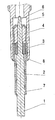
- the single FIGURE shows a sectional view of the combustion chamber side part of a Druckmessglühkerze with the embodiment of the invention DruckmessSWstabes.
- the Druckmessglühkerzenteil shown in the drawing essentially comprises a heating element 1, 2, 3, 4, which is arranged in a plug body 5 so that it projects axially thereof from the combustion chamber side.
- the plug body 5 is sealed by a sealing seat 8 to the cylinder head of the internal combustion engine.
- the heating rod 1, 2, 3, 4 consists of a heating element 1, which is preferably formed of a ceramic material, and a heating element 1 outside and in the combustion chamber side part with a certain play surrounding support tube 2.
- a pressure sensor 3, for example, a piezoelectric Element may be and generates an electrical signal responsive to a mechanical stress, is arranged with a certain play between the heating element 1 and the support tube 2 such that a combustion chamber side lying on the heating element pressure is transmitted to the pressure sensor 3.
- the support tube 2 may be made of a metal material, i. an electrically conductive material, so that it contacts the heating element 1, which is electrically contacted on the one hand via an inner pole 6, on the other hand via an outer pole 7 and thereby ensures the current return at the outer pole 7.
- the support tube 2 is axially stretchable, clamped with the heating element 1 in the axial direction and forms together with the pressure sensor 3, a power circuit responsive to external pressures, such as the combustion pressures inside the cylinder of the internal combustion engine.
- the axial extensibility of the support tube 2 can be adapted to the particular needs of the measurement task, that provided on the support tube 2, one or more bellows-like deformations are. Due to the formation of these bellows-like deformations, the elasticity in the axial direction can be adjusted as desired.
- a press-in sleeve 4 is provided on the connection side in the support tube 2 so that it closes the power circuit.
- the support tube 2 is crimped on the press-in sleeve 4, wherein the press-in sleeve 4 serves as a stable element, which makes it possible to compress the entire assembly of heating element 1, support tube 2, press-fit 4 and pressure sensor 3 tight in the plug body 5. This can be done by pressing the heating element 1 into the press-fit sleeve 4 or by radial force in the region of the press-in sleeve 4.
- the contacting of the heating element 1 is effected by means of suitable lines which are integrated in the press-fit sleeve 4 or via a contact between the heating element 1 and the press-in sleeve 4.
- the support tube 2 is arranged under an axial bias directly on the heating element 1 and is the pressure sensor 3 in the space between the heating element 1 and the support tube. 2
- the support tube 2 has several functions, namely the construction of a bias voltage on the heating element 1, the power transmission to the pressure sensor 3 by the aforementioned support tube 2 is relieved, the support of the heating element 1, the power transmission of heating element 1 and the seal in the plug body fifth
- the heating element 1 runs axially continuously from the combustion chamber side to the connection side to the inner pole 6 located there, it is also possible that the heating element 1 ends on the combustion chamber side of the pressure sensor 3 and this not as in the illustrated Embodiment in the form of a ring but as a solid, for example, cuboid or solid cylindrical element formed is.
- the electrical connection is achieved instead of via the inner pole 6 in the illustrated embodiment via an external power supply.
- the pressure sensor 3 consists for example of a temperature-stable piezoelectric quartz element or of an element of a piezoelectric functional ceramic.
- a linear pressure / charge conversion can be set, which can be converted via a suitable electronics in a conventional voltage signal as the sensor output signal. Due to the thermally exposed mounting position, it is preferable to provide a temperature compensation of the measurement signal in the electronics.
- the heating rod has been described in a Druckmessglühkerze with a plug body 5
- the heating element can be used in any Druckmessglüh observed having a corresponding support for the heating element.
- the heating element in the connection-side region in particular in the region of the press-in sleeve 4 in the holder fixedly arranged, for example, is press-fitted. It is also possible to weld the heating element in such a holder, in which case the press-in sleeve 4 does not necessarily have to be provided.
- the pressure sensor of deformations of the holder e.g. the cylinder head of an internal combustion engine, in which the heating element is arranged, is decoupled.
- the pressure measuring device operates in the following way: Due to the axially strained arrangement of the support tube 2 on the heating element 1 is located on the pressure sensor 3, an axial bias. If the heating element is subjected to an external pressure, this adds to the already existing on the pressure sensor 3 bias in Form of an additional force. The resulting voltage signal is tapped and processed to a pressure applied to the heating element 1 reproducing pressure signal.
Description
- Die Erfindung betrifft eine Druckmessglüheinrichtung, insbesondere eine Druckmessglühkerze mit einem elektrischen Heizelement und einem Drucksensor, auf den ein am Heizelement liegender Druck übertragen wird. Die Merkmale des Oberbegriffes des Anspruches 1 sind aus
DE 103 46 330 A1 bekannt. - Eine Druckmessglüheinrlchtung oder eine Druckmessglühkerze mit einem Heizstab, wie aus
DE 10346 330A1 bekannt, wird bei selbstzündenden Brennkraftmaschinen verwandt und hat neben der üblichen Glühfunktion eine Druckmessfunktion, über die beispielsweise der im Zylinder der Brennkraftmaschine herrschende Druck ermittelt werden kann. - Übliche Druckmessglüheinrichtungen weisen einen Heizstab und einen Drucksensor auf, der durch den im Zylinder der Brennkraftmaschine herrschenden Druck beaufschlagt wird, der über den Heizstab auf den Drucksensor übertragen wird.
- Druckmessgiüheinrichtungen oder Druckmessglühkerzen, die einen Heizstab und einen Drucksensor umfassen, sind beispielsweise aus der
DE 103 43 521 A1 ,DE 10 2004 044 727 A1 , derDE 10 2004 024 . 341 A1, derWO2005/043039 A1 und derWO2005/040681 A1 bekannt. - Aufgrund der voluminösen Geometrie und des Gewichtes der Druck- oder Kraftübertragungseinrichtungen zum Drucksensor liegt bei diesen bekannten Einrichtungen soft eine Störungen hervorrufende Eigenfrequenzsituation innerhalb des Messbandes vor.
- Die der Erfindung zugrunde liegende Aufgabe besteht daher darin, eine Druckmessglüheinrichtung, insbesondere für eine Druckmessglühkerze zu schafen, die einen einfachen Aufbau hat und dementsprechenden mit geringen Kosten verbunden ist.
- Diese Aufgabe wird durch eine Druckmessglüheinrichtüng der im Anspruch 1 angegebenen Art gelöst.
- Bei der erfindungsgemäßen Druckmessglüheinrichtung ist die 0Druckmesseinrichtung in den Heizstab integriert, werden keine speziellen Dichtungen und Führungen benötigt, was die Kosten herabsetzt, und kann durch Miniaturisierung die Eigenfrequenzproblematik vermieden werden.
- Besonders bevorzugte Ausgestaltungen und Weiterbildungen der erfindungsgemäßen Druckmessglüheihrichtung sind Gegenstand der Ansprüche 2 bis 8.
- Im Folgenden wird anhand der zugehörigen Zeichnung ein besonders bevorzugtes Ausführungsbeispiel der erfindungsgemäßen Druckmessglüheinrichtung näher beschrieben.
- Die einzige Figur zeigt in einer Schnittansicht den brennraumseitigen Teil einer Druckmessglühkerze mit dem Ausführungsbeispiel des erfindungsgemäßen Druckmessheizstabes.
- Der in der Zeichnung dargestellte Druckmessglühkerzenteil umfasst im Wesentlichen einen Heizstab 1, 2, 3, 4, der in einem Kerzenkörper 5 so angeordnet ist, dass er davon brennraumseitig axial vorsteht. Der Kerzenkörper 5 ist durch einen Dichtsitz 8 zum Zylinderkopf der Brennkraftmaschine abgedichtet.
- Der Heizstab 1, 2, 3, 4 besteht aus einem Heizelement 1, das vorzugsweise aus einem keramischen Material gebildet ist, und einem das Heizelement 1 außen und im brennraumseitigen Teil mit einem gewissen Spiel umgebenden Stützrohr 2. Ein Drucksensor 3, der beispielsweise ein piezoelektrisches Element sein kann und auf eine mechanische Spannung ansprechend ein elektrisches Signal erzeugt, ist mit einem gewissen Spiel zwischen dem Heizelement 1 und dem Stützrohr 2 derart angeordnet, dass ein brennraumseitig am Heizstab liegender Druck auf den Drucksensor 3 übertragen wird.
- Das Stützrohr 2 kann aus einem Metallmaterial, d.h. einem elektrisch leitenden Material bestehen, so dass es das Heizelement 1, das zum einen über einen Innenpol 6 elektrisch kontaktiert ist, zum anderen über einen Außenpol 7 kontaktiert und dabei für die Stromrückführung am Außenpol 7 sorgt.
- Das Stützrohr 2 ist axial dehnfähig, mit dem Heizelement 1 in axialer Richtung verspannt und bildet zusammen mit dem Drucksensor 3 einen Kraftkreislauf, der auf äußere Drücke, wie beispielsweise die Verbrennungsdrücke im Inneren des Zylinders der Brennkraftmaschine anspricht.
- Die axiale Dehnfähigkeit des Stützrohres 2 kann dadurch an die jeweiligen Bedürfnisse der Messaufgabe angepasst werden, dass am Stützrohr 2 ein oder mehrere faltenbalgartige Verformungen vorgesehen sind. Durch die Ausbildung dieser faltenbalgartigen Verformungen kann die Dehnfähigkeit in axialer Richtung nach Wunsch eingestellt werden.
- Eine Einpresshülse 4 ist anschlussseitig im Stützrohr 2 so vorgesehen, dass sie den Kraftkreislauf schließt. Hierzu ist das Stützrohr 2 über die Einpresshülse 4 verbördelt, wobei die Einpresshülse 4 als stabiles Element dient, das es ermöglicht, die gesamte Baugruppe aus Heizelement 1, Stützrohr 2, Einpresshülse 4 und Drucksensor 3 dicht im Kerzenkörper 5 zu verpressen. Das kann durch Einpressen des Heizelements 1 in die Einpresshülse 4 oder durch radiale Krafteinwirkung im Bereich der Einpresshülse 4 erfolgen.
- Die Kontaktierung des Heizelementes 1 erfolgt durch geeignete Leitungen, die in die Einpresshülse 4 integriert sind oder über eine Kontaktierung zwischen dem Heizelement 1 und der Einpresshülse 4.
- Bei des erfindungsgemäßen Druckmessglüheinrichtung ist somit das Stützrohr 2 unter einer axialen Vorspannung direkt auf dem Heizelement 1 angeordnet und befindet sich der Drucksensor 3 im Bauraum zwischen dem Heizelement 1 und dem Stützrohr 2.
- Das Stützrohr 2 hat mehrere Funktionen, nämlich des Aufbaus einer Vorspannung am Heizelement 1, der Kraftübertragung auf den Drucksensor 3, indem das vorgenannte Stützrohr 2 entlastet wird, der Stütze des Heizelements 1, der Stromübertragung von Heizelement 1 und der Abdichtung im Kerzenkörper 5.
- Obwohl bei dem oben beschriebenen und in der Zeichnung dargestellten Ausführungsbeispiel das Heizelement 1 axial durchgehend von der Brennraumseite zur Anschlussseite zu dem dort befindlichen Innenpol 6 verläuft, ist es auch möglich, dass das Heizelement 1 brennraumseitig am Drucksensor 3 endet und dieser nicht wie bei dem dargestellten Ausführungsbeispiel in Form eines Ringes sondern als ein massives, beispielsweise quaderförmiges oder massiv zylindrisches Element ausgebildet ist. In diesem Fall wird der elektrische Anschluss statt über den Innenpol 6 bei dem dargestellten Ausführungsbeispiel über eine äußere Stromführung erzielt.
- Der Drucksensor 3 besteht beispielsweise aus einem temperaturstabilen piezoelektrischen Quarzelement oder aus einem Element aus einer piezoelektrischen Funktionskeramik. Bei einem derartigen Drucksensor lässt sich eine lineare Druck/Ladungswandlung einstellen, die über eine geeignete Elektronik in ein übliches Spannungssignal als Sensorausgangssignal umgesetzt werden kann. Aufgrund der thermisch exponierten Einbaulage ist es bevorzugt, in der Elektronik eine Temperaturkompensation des Messsignals vorzusehen.
- Obwohl im obigen die Verwendung des Heizstabes bei einer Druckmessglühkerze mit einem Kerzenkörper 5 beschrieben wurde, kann der Heizstab bei einer beliebigen Druckmessglüheinrichtung verwandt werden, die eine entsprechende Halterung für den Heizstab aufweist.
- Entscheidend ist, dass der Heizstab im anschlussseitigen Bereich, insbesondere im Bereich der Einpresshülse 4 in der Halterung fest angeordnet beispielsweise pressgepasst ist. Es ist auch möglich, den Heizstab in eine derartige Halterung einzuschweißen, wobei in diesem Fall die Einpresshülse 4 nicht notwendigerweise vorgesehen sein muss.
- Durch diese Ausbildung wird erreicht, dass der Drucksensor von Verformungen der Halterung, z.B. des Zylinderkopfes einer Brennkraftmaschine, in dem der Heizstab angeordnet ist, entkoppelt ist.
- Die erfindungsgemäße Druckmessglüheinrichtung arbeitet in der folgenden Weise:
Aufgrund der axial verspannten Anordnung des Stützrohres 2 auf dem Heizelement 1 liegt am Drucksensor 3 eine axiale Vorspannung. Wenn der Heizstab mit einem äußeren Druck beaufschlagt wird, addiert sich dieser zu der am Drucksensor 3 bereits liegenden Vorspannung in Form einer zusätzlichen Kraft. Das daraus resultierende Spannungssignal wird abgegriffen und zu einem den am Heizelement 1 liegenden Druck wiedergebenden Drucksignal verarbeitet.
Claims (8)
- Druckmessglüheinrichtung; insbesondere Druckmessglühkerze, zum Einsetzen in einen Zylinderkopf einer Brennkraftmaschine, umfassend einen Kerzenkörper (5), der brennraumseitig einen Dichtsitz (8) aufweist zum Abdichten des Kerzenkörpers (5) gegenüber dem ZyLinderkopf; und einen fest in dem Kerzenkörper (5) angeordneten Heizstab (1, 2, 3), der ein elektrisches Heizelement (1) und einen Drucksensor (3) aufweist,
dadurch gekennzeichnet, dass
ein brennraumseitiger Teil des Heizelementes (1) von einem axial dehnfähiger Stützrohr (2) umgeben ist, der Drucksensor (3) im Bauraum zwischen dem Heizelement (1) und dem Stützrohr (2) angeordnet ist, und das Stützrohr (2) unter einer axialen Vorspannung auf dem Heizelement (3:) angeordnet ist, wodurch der Drucksensor (3) axial vorgespannt und von Verformungen des Kerzenkörpers (5) entkoppelt ist. - Druckmessglüheinrichtung nach Anspruch 1, dadurch gekennzeichnet, dass der Heizstab ferner eine Einpresshülse (4) aufweist, die im Stützrohr (2) anschlussseitig angeordnet ist.
- Druckmessglüheinrichtung nach Anspruch 2, dadurch gekennzeichnet, dass der Heizstab (1, 2, 3) lediglich im Bereich der Einpresshülse (4) fest in dem Kerzenkörper (5) angeordnet ist.
- Druckmessglüheinrichtung nach einem der vorhergehenden Ansprüche, dadurch gekennzeichnet, dass der Heizstab (1, 2, 3) in dem Kerzenkörper (5) pressgepasst ist.
- Druckmessglüheinrichtüng nach einem der vorhergehenden Ansprüche, dadurch gekennzeichnet, dass der Drucksensor (3) ein ringförmiges Element ist, das außen auf dem Heizelement (1) sitzt, das stabförmig ausgebildet ist und anschlussseitig mit einem Innenpol (6) und brennraumseitig mit einem Außenpol (7) versehen ist, der das Stützrohr (2) kontaktiert; welches Stützrohr (2) aus einem elektrisch leitenden Material gebildet ist.
- Druckmessglüheinrichtung nach einem der vorhergehenden Ansprüche, dadurch gekennzeichnet, dass der Drucksensor (3) aus einem massiven element gebildet ist, das brennraumseitig vom Heizelement (1) kontaktiert wird, wobei die elektrischen Zuleitungen zum Heizelement (1) über eine äußere Stromführung erfolgen.
- Druckmessglüheinrichtung nach einem der vorhergehenden Ansprüche, dadurch gekennzeichnet, dass der Drucksensor (3) auf einer brennraumseitig am Heizelement (1) ausgebildeten Schulter sitzt.
- Druckmessglüheinrichtung nach einem der vorhergehenden Ansprüche, dadurch gekennzeichnet, dass das Stützrohr (2) durch Ausbildung von faltenbalgartigen Verformungen axial dehnfähig ausgebindet ist.
Applications Claiming Priority (1)
| Application Number | Priority Date | Filing Date | Title |
|---|---|---|---|
| DE102005051817A DE102005051817B4 (de) | 2005-10-28 | 2005-10-28 | Druckmessglüheinrichtung, insbesondere Druckmessglühkerze |
Publications (3)
| Publication Number | Publication Date |
|---|---|
| EP1780468A2 EP1780468A2 (de) | 2007-05-02 |
| EP1780468A3 EP1780468A3 (de) | 2007-07-25 |
| EP1780468B1 true EP1780468B1 (de) | 2011-04-27 |
Family
ID=37694273
Family Applications (1)
| Application Number | Title | Priority Date | Filing Date |
|---|---|---|---|
| EP06021416A Not-in-force EP1780468B1 (de) | 2005-10-28 | 2006-10-12 | Druckmessglüheinrichtung |
Country Status (6)
| Country | Link |
|---|---|
| US (1) | US7829824B2 (de) |
| EP (1) | EP1780468B1 (de) |
| JP (1) | JP5230924B2 (de) |
| KR (1) | KR101302439B1 (de) |
| AT (1) | ATE507437T1 (de) |
| DE (2) | DE102005051817B4 (de) |
Families Citing this family (22)
| Publication number | Priority date | Publication date | Assignee | Title |
|---|---|---|---|---|
| DE102004011097A1 (de) * | 2004-03-06 | 2005-09-22 | Robert Bosch Gmbh | Vorrichtung zur Erfassung des Brennraumdrucks bei einer Brennkraftmaschine |
| DE102004045383A1 (de) * | 2004-09-18 | 2006-03-23 | Robert Bosch Gmbh | Glühkerze mit Brennraumdrucksensor |
| JP5047770B2 (ja) * | 2007-12-19 | 2012-10-10 | 日本特殊陶業株式会社 | 燃焼圧力センサ付きグロープラグ |
| DE102008009441B4 (de) * | 2008-02-13 | 2011-08-25 | Beru AG, 71636 | Druckmessglühkerze |
| JP5161121B2 (ja) * | 2008-03-28 | 2013-03-13 | 日本特殊陶業株式会社 | グロープラグ |
| JP2009243710A (ja) * | 2008-03-28 | 2009-10-22 | Ngk Spark Plug Co Ltd | グロープラグ |
| DE102008017110B3 (de) * | 2008-04-02 | 2009-09-10 | Beru Ag | Druckmessglühkerze |
| DE102008020510B4 (de) * | 2008-04-23 | 2010-02-11 | Beru Ag | Vorrichtung und Verfahren zur Ermittlung des Brennraumdruckes |
| US8217309B2 (en) * | 2008-12-15 | 2012-07-10 | Federal-Mogul Italy Srl. | Glow plug with pressure sensing canister |
| DE102009048643B4 (de) * | 2009-09-30 | 2013-11-28 | Borgwarner Beru Systems Gmbh | Glühkerze und Verfahren zum Verbinden eines Stifts aus einer Funktionskeramik mit einer Metallhülse |
| DE102010037476B4 (de) * | 2010-09-10 | 2012-04-26 | Borgwarner Beru Systems Gmbh | Druckmessgerät |
| EP2469171A1 (de) | 2010-12-22 | 2012-06-27 | HIDRIA AET Druzba za proizvodnjo vzignih sistemov in elektronike d.o.o. | Zündkerze mit Kerzenkörper aus mehreren End-an-End-Rohren |
| EP2472181B1 (de) | 2010-12-22 | 2014-09-10 | HIDRIA AET Druzba za proizvodnjo vzignih sistemov in elektronike d.o.o. | Zündkerze mit Lastfühlhülse um einen Heizstab außerhalb einer Brennkammer |
| JP5838033B2 (ja) * | 2011-02-25 | 2015-12-24 | 日本特殊陶業株式会社 | 燃焼圧力センサ付きグロープラグ |
| DE102011007586A1 (de) * | 2011-04-18 | 2012-10-18 | Robert Bosch Gmbh | Abdichtung für eine Heizvorrichtung, insbesondere für eine Glühkerze |
| DE102011054511B4 (de) * | 2011-07-05 | 2013-08-29 | Borgwarner Beru Systems Gmbh | Glühkerze |
| US8857249B2 (en) | 2011-08-22 | 2014-10-14 | BorgWarner BERU Systems, GmbH | Dual diaphragm combustion pressure measuring device |
| JP5965179B2 (ja) * | 2012-03-29 | 2016-08-03 | 日本特殊陶業株式会社 | グロープラグ及びその製造方法 |
| DE102013101177B4 (de) | 2013-02-06 | 2016-08-04 | Borgwarner Ludwigsburg Gmbh | Brennraumdruckmessgerät |
| JP5575291B2 (ja) * | 2013-03-21 | 2014-08-20 | 日本特殊陶業株式会社 | グロープラグ |
| DE102016114929B4 (de) * | 2016-08-11 | 2018-05-09 | Borgwarner Ludwigsburg Gmbh | Druckmessglühkerze |
| DE102018108427B3 (de) | 2018-04-10 | 2019-07-25 | Borgwarner Ludwigsburg Gmbh | Heizstab für eine Glühkerze sowie Verfahren zur Herstellung eines Heizstabs und Glühkerze |
Family Cites Families (23)
| Publication number | Priority date | Publication date | Assignee | Title |
|---|---|---|---|---|
| JPS5985932A (ja) * | 1982-11-09 | 1984-05-18 | Nippon Soken Inc | グロ−プラグ |
| JP3177819B2 (ja) * | 1995-09-05 | 2001-06-18 | 株式会社ユニシアジェックス | 内燃機関の筒内圧力検出装置 |
| JP3885515B2 (ja) * | 2001-04-26 | 2007-02-21 | 株式会社デンソー | 燃焼圧センサ付きグロープラグ |
| DE10205819A1 (de) | 2002-02-13 | 2003-08-14 | Bosch Gmbh Robert | Vorrichtung zum Betrieb einer Brennkraftmaschine |
| JP2004278934A (ja) * | 2003-03-17 | 2004-10-07 | Ngk Spark Plug Co Ltd | 燃焼圧検知機能付きグロープラグ |
| DE102004044727A1 (de) * | 2003-09-19 | 2006-03-16 | Beru Ag | Druckmessglühkerze für einen Dieselmotor |
| DE10343521A1 (de) * | 2003-09-19 | 2005-04-21 | Beru Ag | Druckmessglühkerze für einen Dieselmotor |
| DE10346330B4 (de) * | 2003-10-06 | 2005-09-22 | Beru Ag | Druckmessglühkerze für einen Dieselmotor |
| FR2861836B1 (fr) * | 2003-10-29 | 2006-03-10 | Siemens Vdo Automotive | Bougie de prechauffage comprenant un capteur de pression et moteur ainsi equipe |
| JP2005180855A (ja) * | 2003-12-22 | 2005-07-07 | Bosch Automotive Systems Corp | セラミックスヒータ型グロープラグ |
| US6948372B2 (en) * | 2004-01-08 | 2005-09-27 | Delphi Technologies, Inc. | Method of connection to a spark plug pressure sensor |
| DE102004011097A1 (de) * | 2004-03-06 | 2005-09-22 | Robert Bosch Gmbh | Vorrichtung zur Erfassung des Brennraumdrucks bei einer Brennkraftmaschine |
| DE102004011098A1 (de) * | 2004-03-06 | 2005-09-22 | Robert Bosch Gmbh | Vorrichtung zur Erfassung des Brennraumdrucks bei einer Brennkraftmaschine |
| DE102004024341B3 (de) * | 2004-05-17 | 2005-12-22 | Beru Ag | Druckmessglühkerze |
| JP2006300046A (ja) * | 2004-08-05 | 2006-11-02 | Ngk Spark Plug Co Ltd | 燃焼圧検知機能付グロープラグ |
| DE102004047143A1 (de) | 2004-09-29 | 2006-04-06 | Robert Bosch Gmbh | Piezoelektrischer Brennraum-Drucksensor mit einem Druckübertragungsstift |
| JP4316474B2 (ja) * | 2004-11-02 | 2009-08-19 | 株式会社デンソー | 燃焼室圧力検出装置 |
| DE102004063749A1 (de) * | 2004-12-29 | 2006-07-13 | Robert Bosch Gmbh | Stahlmembran für Brennraumdrucksensoren |
| DE102005017802A1 (de) * | 2005-04-18 | 2006-10-19 | Robert Bosch Gmbh | Glühstiftkerze mit Brennraumdrucksensor und Dichtelement |
| US7214908B2 (en) * | 2005-07-28 | 2007-05-08 | Wlodarczyk Marek T | Glow plug integrated pressure sensor with filter trap |
| JP4897467B2 (ja) * | 2006-12-19 | 2012-03-14 | 日本特殊陶業株式会社 | グロープラグおよびその製造方法 |
| JP4386117B2 (ja) * | 2007-08-30 | 2009-12-16 | 株式会社デンソー | 燃焼圧センサ付きグロープラグ |
| JP5161121B2 (ja) * | 2008-03-28 | 2013-03-13 | 日本特殊陶業株式会社 | グロープラグ |
-
2005
- 2005-10-28 DE DE102005051817A patent/DE102005051817B4/de not_active Expired - Fee Related
-
2006
- 2006-10-12 EP EP06021416A patent/EP1780468B1/de not_active Not-in-force
- 2006-10-12 AT AT06021416T patent/ATE507437T1/de active
- 2006-10-12 DE DE502006009382T patent/DE502006009382D1/de active Active
- 2006-10-26 US US11/553,166 patent/US7829824B2/en not_active Expired - Fee Related
- 2006-10-26 KR KR1020060104554A patent/KR101302439B1/ko not_active IP Right Cessation
- 2006-10-30 JP JP2006293904A patent/JP5230924B2/ja not_active Expired - Fee Related
Also Published As
| Publication number | Publication date |
|---|---|
| ATE507437T1 (de) | 2011-05-15 |
| US20070095811A1 (en) | 2007-05-03 |
| JP5230924B2 (ja) | 2013-07-10 |
| EP1780468A3 (de) | 2007-07-25 |
| KR101302439B1 (ko) | 2013-09-02 |
| DE102005051817A1 (de) | 2007-05-03 |
| EP1780468A2 (de) | 2007-05-02 |
| DE102005051817B4 (de) | 2008-06-05 |
| DE502006009382D1 (de) | 2011-06-09 |
| KR20070045965A (ko) | 2007-05-02 |
| JP2007120939A (ja) | 2007-05-17 |
| US7829824B2 (en) | 2010-11-09 |
Similar Documents
| Publication | Publication Date | Title |
|---|---|---|
| EP1780468B1 (de) | Druckmessglüheinrichtung | |
| EP1517086B1 (de) | Druckmessglühkerze für einen Dieselmotor | |
| EP1637806B1 (de) | Druckmessglühkerze für einen Dieselmotor | |
| EP1989485B1 (de) | Druckmesseinrichtung | |
| EP1792156B1 (de) | Vorrichtung zur erfassung des drucks in einem brennraum einer verbrennungskraftmaschine | |
| EP1794500B1 (de) | Glühstiftkerze mit elastisch gelagertem glühstift | |
| EP1977164B1 (de) | Glühstiftkerze | |
| DE60035854T2 (de) | Anordnungstruktur eines Motorteils mit Verbrennungsdrucksensor in der Maschine | |
| US6973820B2 (en) | Combustion pressure sensor designed to ensure stability of output characteristic and sensitivity | |
| EP0040390A2 (de) | Drucksensor für Verbrennungsmotor | |
| EP0718612B1 (de) | Zündkerze mit Kraftmesselement und geteiltem Isolierkörper | |
| DE10346294A1 (de) | Glühkerze mit Verbrennungsdrucksensor | |
| EP1875135B1 (de) | Glühstiftkerze mit brennraumdrucksensor und dichtelement | |
| WO2013117417A1 (de) | Druckmessglühkerze | |
| WO2008043594A2 (de) | Druckmesseinrichtung | |
| DE102005026074A1 (de) | Glühstiftkerze mit einem integrierten Brennraumdrucksensor | |
| DE102005016463A1 (de) | Glühstiftkerze mit integriertem Druckmesselement | |
| DE102006041124A1 (de) | Glühkerze mit eingebautem Drucksensor | |
| DE102004044727A1 (de) | Druckmessglühkerze für einen Dieselmotor | |
| WO2005114054A1 (de) | Glühstiftkerze mit integriertem drucksensor | |
| EP1754001B1 (de) | Glühstiftkerze mit einem gaskanal zur brennraumdruckmessung | |
| WO2005045319A1 (de) | Glühstifkerze mit integriertem drucksensor | |
| DE102005016464A1 (de) | Glühstiftkerze mit einem integrierten temperaturstabilen Brennraumdrucksensor | |
| EP0997687A1 (de) | Rohrförmige Heiz- oder Messvorrichtung | |
| DE102005016462A1 (de) | Glühstiftkerze mit integriertem temperaturkompensierten Brennraumdrucksensor |
Legal Events
| Date | Code | Title | Description |
|---|---|---|---|
| PUAI | Public reference made under article 153(3) epc to a published international application that has entered the european phase |
Free format text: ORIGINAL CODE: 0009012 |
|
| AK | Designated contracting states |
Kind code of ref document: A2 Designated state(s): AT BE BG CH CY CZ DE DK EE ES FI FR GB GR HU IE IS IT LI LT LU LV MC NL PL PT RO SE SI SK TR |
|
| AX | Request for extension of the european patent |
Extension state: AL BA HR MK YU |
|
| PUAL | Search report despatched |
Free format text: ORIGINAL CODE: 0009013 |
|
| AK | Designated contracting states |
Kind code of ref document: A3 Designated state(s): AT BE BG CH CY CZ DE DK EE ES FI FR GB GR HU IE IS IT LI LT LU LV MC NL PL PT RO SE SI SK TR |
|
| AX | Request for extension of the european patent |
Extension state: AL BA HR MK YU |
|
| 17P | Request for examination filed |
Effective date: 20080125 |
|
| 17Q | First examination report despatched |
Effective date: 20080229 |
|
| AKX | Designation fees paid |
Designated state(s): AT BE BG CH CY CZ DE DK EE ES FI FR GB GR HU IE IS IT LI LT LU LV MC NL PL PT RO SE SI SK TR |
|
| GRAP | Despatch of communication of intention to grant a patent |
Free format text: ORIGINAL CODE: EPIDOSNIGR1 |
|
| RTI1 | Title (correction) |
Free format text: BOUGIE DE PRECHAUFFAGE AVEC CAPTEUR DE PRESSION |
|
| GRAS | Grant fee paid |
Free format text: ORIGINAL CODE: EPIDOSNIGR3 |
|
| GRAA | (expected) grant |
Free format text: ORIGINAL CODE: 0009210 |
|
| AK | Designated contracting states |
Kind code of ref document: B1 Designated state(s): AT BE BG CH CY CZ DE DK EE ES FI FR GB GR HU IE IS IT LI LT LU LV MC NL PL PT RO SE SI SK TR |
|
| REG | Reference to a national code |
Ref country code: GB Ref legal event code: FG4D Free format text: NOT ENGLISH |
|
| REG | Reference to a national code |
Ref country code: CH Ref legal event code: EP |
|
| REG | Reference to a national code |
Ref country code: IE Ref legal event code: FG4D Free format text: LANGUAGE OF EP DOCUMENT: GERMAN |
|
| REF | Corresponds to: |
Ref document number: 502006009382 Country of ref document: DE Date of ref document: 20110609 Kind code of ref document: P |
|
| REG | Reference to a national code |
Ref country code: DE Ref legal event code: R096 Ref document number: 502006009382 Country of ref document: DE Effective date: 20110609 |
|
| REG | Reference to a national code |
Ref country code: NL Ref legal event code: VDEP Effective date: 20110427 |
|
| LTIE | Lt: invalidation of european patent or patent extension |
Effective date: 20110427 |
|
| PG25 | Lapsed in a contracting state [announced via postgrant information from national office to epo] |
Ref country code: SE Free format text: LAPSE BECAUSE OF FAILURE TO SUBMIT A TRANSLATION OF THE DESCRIPTION OR TO PAY THE FEE WITHIN THE PRESCRIBED TIME-LIMIT Effective date: 20110427 Ref country code: LT Free format text: LAPSE BECAUSE OF FAILURE TO SUBMIT A TRANSLATION OF THE DESCRIPTION OR TO PAY THE FEE WITHIN THE PRESCRIBED TIME-LIMIT Effective date: 20110427 Ref country code: PT Free format text: LAPSE BECAUSE OF FAILURE TO SUBMIT A TRANSLATION OF THE DESCRIPTION OR TO PAY THE FEE WITHIN THE PRESCRIBED TIME-LIMIT Effective date: 20110829 |
|
| REG | Reference to a national code |
Ref country code: IE Ref legal event code: FD4D |
|
| PG25 | Lapsed in a contracting state [announced via postgrant information from national office to epo] |
Ref country code: IS Free format text: LAPSE BECAUSE OF FAILURE TO SUBMIT A TRANSLATION OF THE DESCRIPTION OR TO PAY THE FEE WITHIN THE PRESCRIBED TIME-LIMIT Effective date: 20110827 Ref country code: SI Free format text: LAPSE BECAUSE OF FAILURE TO SUBMIT A TRANSLATION OF THE DESCRIPTION OR TO PAY THE FEE WITHIN THE PRESCRIBED TIME-LIMIT Effective date: 20110427 Ref country code: GR Free format text: LAPSE BECAUSE OF FAILURE TO SUBMIT A TRANSLATION OF THE DESCRIPTION OR TO PAY THE FEE WITHIN THE PRESCRIBED TIME-LIMIT Effective date: 20110728 Ref country code: FI Free format text: LAPSE BECAUSE OF FAILURE TO SUBMIT A TRANSLATION OF THE DESCRIPTION OR TO PAY THE FEE WITHIN THE PRESCRIBED TIME-LIMIT Effective date: 20110427 Ref country code: LV Free format text: LAPSE BECAUSE OF FAILURE TO SUBMIT A TRANSLATION OF THE DESCRIPTION OR TO PAY THE FEE WITHIN THE PRESCRIBED TIME-LIMIT Effective date: 20110427 Ref country code: ES Free format text: LAPSE BECAUSE OF FAILURE TO SUBMIT A TRANSLATION OF THE DESCRIPTION OR TO PAY THE FEE WITHIN THE PRESCRIBED TIME-LIMIT Effective date: 20110807 Ref country code: CY Free format text: LAPSE BECAUSE OF FAILURE TO SUBMIT A TRANSLATION OF THE DESCRIPTION OR TO PAY THE FEE WITHIN THE PRESCRIBED TIME-LIMIT Effective date: 20110427 |
|
| PG25 | Lapsed in a contracting state [announced via postgrant information from national office to epo] |
Ref country code: NL Free format text: LAPSE BECAUSE OF FAILURE TO SUBMIT A TRANSLATION OF THE DESCRIPTION OR TO PAY THE FEE WITHIN THE PRESCRIBED TIME-LIMIT Effective date: 20110427 |
|
| PG25 | Lapsed in a contracting state [announced via postgrant information from national office to epo] |
Ref country code: EE Free format text: LAPSE BECAUSE OF FAILURE TO SUBMIT A TRANSLATION OF THE DESCRIPTION OR TO PAY THE FEE WITHIN THE PRESCRIBED TIME-LIMIT Effective date: 20110427 Ref country code: IE Free format text: LAPSE BECAUSE OF FAILURE TO SUBMIT A TRANSLATION OF THE DESCRIPTION OR TO PAY THE FEE WITHIN THE PRESCRIBED TIME-LIMIT Effective date: 20110427 Ref country code: CZ Free format text: LAPSE BECAUSE OF FAILURE TO SUBMIT A TRANSLATION OF THE DESCRIPTION OR TO PAY THE FEE WITHIN THE PRESCRIBED TIME-LIMIT Effective date: 20110427 |
|
| PG25 | Lapsed in a contracting state [announced via postgrant information from national office to epo] |
Ref country code: RO Free format text: LAPSE BECAUSE OF FAILURE TO SUBMIT A TRANSLATION OF THE DESCRIPTION OR TO PAY THE FEE WITHIN THE PRESCRIBED TIME-LIMIT Effective date: 20110427 Ref country code: SK Free format text: LAPSE BECAUSE OF FAILURE TO SUBMIT A TRANSLATION OF THE DESCRIPTION OR TO PAY THE FEE WITHIN THE PRESCRIBED TIME-LIMIT Effective date: 20110427 Ref country code: PL Free format text: LAPSE BECAUSE OF FAILURE TO SUBMIT A TRANSLATION OF THE DESCRIPTION OR TO PAY THE FEE WITHIN THE PRESCRIBED TIME-LIMIT Effective date: 20110427 Ref country code: DK Free format text: LAPSE BECAUSE OF FAILURE TO SUBMIT A TRANSLATION OF THE DESCRIPTION OR TO PAY THE FEE WITHIN THE PRESCRIBED TIME-LIMIT Effective date: 20110427 |
|
| PLBE | No opposition filed within time limit |
Free format text: ORIGINAL CODE: 0009261 |
|
| STAA | Information on the status of an ep patent application or granted ep patent |
Free format text: STATUS: NO OPPOSITION FILED WITHIN TIME LIMIT |
|
| 26N | No opposition filed |
Effective date: 20120130 |
|
| BERE | Be: lapsed |
Owner name: BERU A.G. Effective date: 20111031 |
|
| REG | Reference to a national code |
Ref country code: DE Ref legal event code: R097 Ref document number: 502006009382 Country of ref document: DE Effective date: 20120130 |
|
| PG25 | Lapsed in a contracting state [announced via postgrant information from national office to epo] |
Ref country code: IT Free format text: LAPSE BECAUSE OF FAILURE TO SUBMIT A TRANSLATION OF THE DESCRIPTION OR TO PAY THE FEE WITHIN THE PRESCRIBED TIME-LIMIT Effective date: 20110427 Ref country code: MC Free format text: LAPSE BECAUSE OF NON-PAYMENT OF DUE FEES Effective date: 20111031 |
|
| REG | Reference to a national code |
Ref country code: CH Ref legal event code: PL |
|
| GBPC | Gb: european patent ceased through non-payment of renewal fee |
Effective date: 20111012 |
|
| REG | Reference to a national code |
Ref country code: FR Ref legal event code: ST Effective date: 20120629 |
|
| PG25 | Lapsed in a contracting state [announced via postgrant information from national office to epo] |
Ref country code: CH Free format text: LAPSE BECAUSE OF NON-PAYMENT OF DUE FEES Effective date: 20111031 Ref country code: LI Free format text: LAPSE BECAUSE OF NON-PAYMENT OF DUE FEES Effective date: 20111031 Ref country code: BE Free format text: LAPSE BECAUSE OF NON-PAYMENT OF DUE FEES Effective date: 20111031 |
|
| PG25 | Lapsed in a contracting state [announced via postgrant information from national office to epo] |
Ref country code: FR Free format text: LAPSE BECAUSE OF NON-PAYMENT OF DUE FEES Effective date: 20111102 Ref country code: GB Free format text: LAPSE BECAUSE OF NON-PAYMENT OF DUE FEES Effective date: 20111012 |
|
| REG | Reference to a national code |
Ref country code: AT Ref legal event code: MM01 Ref document number: 507437 Country of ref document: AT Kind code of ref document: T Effective date: 20111012 |
|
| PG25 | Lapsed in a contracting state [announced via postgrant information from national office to epo] |
Ref country code: AT Free format text: LAPSE BECAUSE OF NON-PAYMENT OF DUE FEES Effective date: 20111012 |
|
| PG25 | Lapsed in a contracting state [announced via postgrant information from national office to epo] |
Ref country code: LU Free format text: LAPSE BECAUSE OF NON-PAYMENT OF DUE FEES Effective date: 20111012 |
|
| PG25 | Lapsed in a contracting state [announced via postgrant information from national office to epo] |
Ref country code: BG Free format text: LAPSE BECAUSE OF FAILURE TO SUBMIT A TRANSLATION OF THE DESCRIPTION OR TO PAY THE FEE WITHIN THE PRESCRIBED TIME-LIMIT Effective date: 20110727 |
|
| PG25 | Lapsed in a contracting state [announced via postgrant information from national office to epo] |
Ref country code: TR Free format text: LAPSE BECAUSE OF FAILURE TO SUBMIT A TRANSLATION OF THE DESCRIPTION OR TO PAY THE FEE WITHIN THE PRESCRIBED TIME-LIMIT Effective date: 20110427 |
|
| PG25 | Lapsed in a contracting state [announced via postgrant information from national office to epo] |
Ref country code: HU Free format text: LAPSE BECAUSE OF FAILURE TO SUBMIT A TRANSLATION OF THE DESCRIPTION OR TO PAY THE FEE WITHIN THE PRESCRIBED TIME-LIMIT Effective date: 20110427 |
|
| REG | Reference to a national code |
Ref country code: DE Ref legal event code: R082 Ref document number: 502006009382 Country of ref document: DE Representative=s name: KOTITSCHKE & HEURUNG PARTNERSCHAFT MBB PATENT-, DE Ref country code: DE Ref legal event code: R082 Ref document number: 502006009382 Country of ref document: DE Representative=s name: DR. RALF KOTITSCHKE, DE Ref country code: DE Ref legal event code: R082 Ref document number: 502006009382 Country of ref document: DE Representative=s name: KOTITSCHKE & HEURUNG PARTNERSCHAFT MBB, DE |
|
| PGFP | Annual fee paid to national office [announced via postgrant information from national office to epo] |
Ref country code: DE Payment date: 20151028 Year of fee payment: 10 |
|
| REG | Reference to a national code |
Ref country code: DE Ref legal event code: R119 Ref document number: 502006009382 Country of ref document: DE |
|
| PG25 | Lapsed in a contracting state [announced via postgrant information from national office to epo] |
Ref country code: DE Free format text: LAPSE BECAUSE OF NON-PAYMENT OF DUE FEES Effective date: 20170503 |