EP1779570B1 - Methode pour detecter une synchronisation de symboles mrof dans un systeme mrof - Google Patents
Methode pour detecter une synchronisation de symboles mrof dans un systeme mrof Download PDFInfo
- Publication number
- EP1779570B1 EP1779570B1 EP05780550.9A EP05780550A EP1779570B1 EP 1779570 B1 EP1779570 B1 EP 1779570B1 EP 05780550 A EP05780550 A EP 05780550A EP 1779570 B1 EP1779570 B1 EP 1779570B1
- Authority
- EP
- European Patent Office
- Prior art keywords
- denotes
- new
- symbol
- ofdm symbol
- length
- Prior art date
- Legal status (The legal status is an assumption and is not a legal conclusion. Google has not performed a legal analysis and makes no representation as to the accuracy of the status listed.)
- Expired - Lifetime
Links
Images


Classifications
-
- H—ELECTRICITY
- H04—ELECTRIC COMMUNICATION TECHNIQUE
- H04L—TRANSMISSION OF DIGITAL INFORMATION, e.g. TELEGRAPHIC COMMUNICATION
- H04L27/00—Modulated-carrier systems
- H04L27/26—Systems using multi-frequency codes
- H04L27/2601—Multicarrier modulation systems
- H04L27/2647—Arrangements specific to the receiver only
- H04L27/2655—Synchronisation arrangements
- H04L27/2662—Symbol synchronisation
-
- H—ELECTRICITY
- H04—ELECTRIC COMMUNICATION TECHNIQUE
- H04L—TRANSMISSION OF DIGITAL INFORMATION, e.g. TELEGRAPHIC COMMUNICATION
- H04L27/00—Modulated-carrier systems
- H04L27/26—Systems using multi-frequency codes
- H04L27/2601—Multicarrier modulation systems
- H04L27/2647—Arrangements specific to the receiver only
- H04L27/2655—Synchronisation arrangements
- H04L27/2668—Details of algorithms
- H04L27/2673—Details of algorithms characterised by synchronisation parameters
- H04L27/2676—Blind, i.e. without using known symbols
- H04L27/2678—Blind, i.e. without using known symbols using cyclostationarities, e.g. cyclic prefix or postfix
-
- H—ELECTRICITY
- H04—ELECTRIC COMMUNICATION TECHNIQUE
- H04L—TRANSMISSION OF DIGITAL INFORMATION, e.g. TELEGRAPHIC COMMUNICATION
- H04L27/00—Modulated-carrier systems
- H04L27/26—Systems using multi-frequency codes
- H04L27/2601—Multicarrier modulation systems
- H04L27/2602—Signal structure
- H04L27/2605—Symbol extensions, e.g. Zero Tail, Unique Word [UW]
- H04L27/2607—Cyclic extensions
Definitions
- the present invention relates to an Orthogonal Frequency Division Multiplexing (OFDM) system, and more particularly, to a scheme for detecting an OFDM symbol timing (synchronization) in an OFDM system.
- OFDM Orthogonal Frequency Division Multiplexing
- an orthogonal frequency division multiplexing is a transmission method for increasing a data transfer rate by converting a serial data column into a plurality of parallel data columns and loading each converted signal (OFDM symbol) on a different subcarrier for transmission.
- an interval between subcarriers is selected as a minimum interval capable of maintaining orthogonality so as to maximize frequency efficiency.
- the OFDM symbol loaded on the subcarrier has a relatively wide symbol interval as compared with that of a single carrier signal.
- an interference of an adjacent symbol ISI
- each subcarrier has a narrow-band characteristic so as to enable a simplified structure of a channel equalizer.
- an inter symbol interference may occur by a path delay.
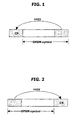
- a transmission symbol in order to avoid the ISI by the path delay, can be constructed by partially copying a rear portion of the OFDM symbol and thereafter inserting a Cyclic Prefix (CP) as illustrated in Fig. 1 , or constructed by partially copying a front portion of the OFDM symbol and thereafter inserting a Cyclic Suffix (CS) as illustrated in Fig. 2 .
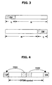
- Fig. 3 illustrates transmission symbols composed of the CP or CS having a length L and an OFDM symbol having a length N.
- the transmission symbol in the conventional OFDM system, as illustrated in Fig. 4 , can be constructed by inserting both the CP and the CS.
- a transmitting end transmits the symbol constructed by such embodiments, and a receiving end detects a timing of the transmission symbol using the characteristics that the CP is identical to the rear portion of the OFDM symbol or the CS is identical to the front portion of the OFDM symbol.
- the receiving end uses the CP to obtain a maximum value of a timing metric M CP (d), as shown in [Formula 1], thereby detecting a starting point of the transmission symbol (detecting of the symbol timing (synchronization)).
- M CP d P CP d R CP d
- the P CP (d) of [Formula 1], as a correlation metric, is obtained by [Formula 2].
- the R CP (d) which is a value to normalize the correlation metric Pcp(d) with respect to a relatively large change in the size of the OFDM symbol (i.e., energy for the OFDM symbol), is obtained by the following [Formula 3].
- a value (i.e., d: time index) for maximizing the timing metric M CP (d) indicates a position of the CP, and accordingly the starting point of the OFDM symbol can be d+L.
- the receiving end uses the CS to obtain the maximum value of the timing metric Mcp(d), as shown in the following [Formula 4], thereby detecting the starting point of the transmission symbol (detecting the symbol timing). That is, the method for obtaining the maximum value of the timing metric Mcp(d) using the CS is equal to the method therefore using the CP.
- M CS d P CS d R CS d
- P cs (d) and the R cs (d) are obtained according to [Formula 5] and [Formula 6], respectively.
- the value d for maximizing the timing metric M cs (d) indicates the starting point of the OFDM symbol, which denotes that the starting point of the transmission symbol is also d.
- the receiving end uses both the CS and the CP to obtain the maximum value of the timing metric, thereby detecting the starting point of the transmission symbol (detecting of the symbol timing),
- the maximum value of the timing metric can be obtained by combining [Formula 1] and [Formula 4].
- the method for detecting the symbol timing of the conventional OFDM system only uses the limited information (i.e., the CP or CS).
- the CP or CS only takes up about 1/4 to 1/32 of the entire symbol length, so as to have a less amount of data. Accordingly, if the less amount of data of the CP or CS is used to obtain the correlation as shown in [Formula 1] and/or [Formula 4], a structural problem in the CP or CS may cause indefiniteness for identifying the maximum value of the correlation, as shown in Fig. 5 . As a result, the receiving end cannot definitely detect the symbol timing, resulting in an undesirable lowering of a reception rate.
- MMSE-based adaptive equalizer with effective use of pilot signal for multi-carrier cdm system Shigehiko Tsumura et.al., proceedings on IEEE seven international symposium on spread spectrum techniques and applications, may be construed to show a technique similar to that of the above paper.
- a low complexity timing and frequency synchronization algorithm for OFDM systems may be construed to disclose a method for detecting a symbol timing in an OFDM system.
- the method may comprise receiving, via the OFDM system configured to support transmissions of signals via radio channels that exhibit multi-path delays, a transmission symbol that has a Cyclic Prefix, CP, or a Cyclic Suffix, CS, inserted in an OFDM symbol.
- an object of the present invention is to provide a method according to claim 1 for detecting an OFDM symbol timing (synchronization) of an OFDM system for performing a symbol timing procedure more precisely without changing a structure of a transmission symbol.
- Another object of the present invention is to provide a new structure of a transmission symbol and a method according to claim 4 for detecting a symbol timing using the structure, thereby precisely performing a symbol timing procedure.
- the timing metric is differently defined when the transmission symbol uses the CP and the CS, respectively.
- the maximum value of the timing metric indicates a position of the CP and a value obtained by adding a length of the CP to the maximum value indicates a starting point of the OFDM symbol (see dependent claim 2).
- the maximum value of the timing metric indicates the starting point of the OFDM symbol (see dependent claim 3).
- the transmission symbol is generated by simultaneously inserting the CP and the CS in front and rear portions of the OFDM symbol, respectively (see dependent claim 5).
- a first embodiment of the present invention proposes a method for detecting a symbol timing (synchronization) capable of obtaining the symbol timing more precisely without changing a structure of a transmission symbol. That is, a transmitting end of an OFDM system transmits a transmission symbol that a CP or CS is inserted in an OFDM symbol, and a receiving end uses a timing metric M new (d) proposed in the present invention to detect a timing (synchronization) of the OFDM symbol.
- [Formula 7] indicates an example of a timing metric M new (d) applied to a method for detecting a symbol timing (synchronization) according to the present invention.
- the example shows a timing metric M new_CP (d) which is applied when the Cyclic Prefix (CP) is used to obtain a symbol timing.
- M new_CP d P new_CP d R new_CP d M CP d ⁇ N 2 ⁇ L
- L denotes a length of the CP
- N denotes a length of the OFDM symbol
- P new_CP (d) denotes a correlation metric.
- the R new_CP (d) denotes a value (i.e., energy of the OFDM symbol) for normalizing the P new_CP (d) with respect to a great change in a size of an OFDM sample.
- P new_CP (d) and the R new_CP (d) are obtained according to the following [Formula 8] and [Formula 9], respectively.
- the r m denotes a reception signal.
- the receiving end obtains the maximum value (d: time index) of the timing metric M new_CP (d) with respect to the reception signal.
- the maximum value d indicates a position of the CP, and a value d+L obtained by adding L to the d may be the starting point of the OFDM symbol.
- the following [Formula 10] indicates another example of the timing metric M new (d) applied to the method for detecting the symbol timing (synchronization) according to the present invention.
- the example shows an example of the timing metric M new_CP (d) applied when the Cyclic Suffix (CS) is used to obtain the symbol timing.
- M new_CS d P new_CS d R new_CS d M CS d ⁇ N 2
- L denotes a length of the CS
- N denotes a length of the OFDM symbol
- P new_CP (d) denotes a correlation metric.
- the R new_CP (d) denotes a value (i.e., energy of the OFDM symbol) for normalizing the P new_CP (d) related to a great change in the size of the OFDM sample.
- P new_CP (d) and the R new_CP (d) are obtained according to the following [Formula 11] and [Formula 12], respectively.
- r m denotes a reception signal
- the receiving end obtains a maximum value d of the timing metric M new_CP (d) for the reception signal, and the obtained maximum value d may be the starting point of the OFDM symbol.
- the data loaded on each subcarrier of the OFDM is composed of a real value and an imaginary value. If the data loaded on each subcarrier of the OFDM is composed of only a real value, the OFDM symbol has a symmetrical structure as shown in Fig. 6 . In this case, when using timing metrics proposed in the present invention, as shown in Fig. 7 , the timing metric of the OFDM symbol using the real-value data can have a precise maximum value.
- each subcarrier of the OFDM includes data of a complex value (real value + imaginary value)
- the OFDM symbol does not have the symmetrical structure.
- the timing metric of the OFDM symbol does not have the precise maximum value.
- the timing metric of the OFDM symbol can have the precise maximum value as shown in Fig. 9 .
- a second embodiment of the present invention proposes a structure of a new transmission symbol using both the CP and the CS and a timing metric capable of detecting a timing (synchronization) of the OFDM symbol more precisely.
- Fig. 10 is a view illustrating an exemplary structure of a new transmission symbol proposed in the present invention.
- the new transmission symbol has a structure in which the CP and the CS are inserted in front and rear portions of the typical OFDM symbol, respectively.
- the transmission symbol according to the present invention and the typical OFDM symbol can be indicated as shown in Fig. 11 . Comparing two drawings, it can be seen that the transmission symbol in accordance with the present invention has a shape that the CP and the CS are inserted in front and rear portions of the typical OFDM symbol, respectively.
- the transmitting end inserts front portion data (e.g., x, a 1 +b 1 ) of the OFDM symbol in the CP, and inserts rear portion data (e.g., a 1 *- b 1 *) in the CS to construct the transmission symbol.
- front portion data e.g., x, a 1 +b 1
- rear portion data e.g., a 1 *- b 1 *
- This structure allows maintaining of continuity of the transmission symbol which is different from the structure shown in Fig. 3 .
- the structure in which the continuity of the symbol is not maintained cannot ensure orthogonality of each subcarrier to be thusly sensitive to a path delay.
- M(d) may use a real value instead of an absolute value.
- [formula 14] and [Formula 15] are formulas for obtaining P(d) and R(d) of the [Formula 13].
- L denotes a length of the CP
- N denotes a length of the OFDM symbol
- rm denotes a reception signal
- the CP and the CS are inserted in the front and rear portions of the OFDM symbol, respectively, to thusly enable maintaining of the continuity of the transmission symbol, and accordingly the orthogonality of each subcarrier is ensured and the inter symbol interference (ISI) caused by the path delay can be reduced. Therefore, as can be seem upon comparison with Fig. 12 , even in an environment that a Signal to Noise Ratio (SNR) is not good, the characteristic of the maximum value of the second embodiment according to the present invention is superior to that by the conventional method using the CP.
- SNR Signal to Noise Ratio
- the present invention provides an Orthogonal Frequency Division Multiplexing (OFDM) system according to claim 6 comprising: a receiver to receive a transmission symbol that has a Cyclic Prefix (CP) or a Cyclic Suffix (CS) inserted in a Orthogonal Frequency Division Multiplexing (OFDM) symbol; and a processor cooperating with the receiver to apply a particular timing metric to the received transmission symbol, to thusly detect a timing synchronization of the OFDM symbol based on a maximum value of the timing metric.
- OFDM Orthogonal Frequency Division Multiplexing
- the present invention provides an Orthogonal Frequency Division Multiplexing (OFDM) system according to claim 7 comprising: a symbol generator to insert a Cyclic Prefix (CP) and a Cyclic Suffix (CS) in an Orthogonal Frequency Division Multiplexing (OFDM) symbol and generating a transmission symbol having continuity; a transmitter to transmit the generated transmission symbol; and a processor cooperating with the symbol generator and the transmitter to apply a particular timing metric to the transmission symbol, to thereby detect a timing synchronization of the OFDM symbol based on a maximum value of the timing metric.
- OFDM Orthogonal Frequency Division Multiplexing
Landscapes
- Engineering & Computer Science (AREA)
- Computer Networks & Wireless Communication (AREA)
- Signal Processing (AREA)
- Synchronisation In Digital Transmission Systems (AREA)
Claims (7)
- Procédé de détection d'une synchronisation de symboles dans un système de multiplexage par répartition orthogonale de la fréquence, OFDM, le procédé comprenant l'étape consistant à :recevoir, via le système OFDM configuré pour supporter des transmissions de signaux via des canaux radio qui montrent des retards multi-trajets, un symbole de transmission qui comporte un préfixe cyclique, CP, ou un suffixe cyclique, CS, inséré dans un symbole OFDM ;caractérisé par l'étape consistant à :
dans lequel une métrique de corrélation Pnew_CP(d) est obtenue par la formule suivante :
dans lequel l'énergie d'un symbole Rnew_CP(d) est obtenue par la formule suivante :
dans lequel une métrique de corrélation Pnew_CP(d) est obtenue par la formule suivante :
dans lequel l'énergie du symbole Rnew_CP(d) est obtenue par la formule suivante : appliquer soit une première métrique de synchronisation soit une deuxième métrique de synchronisation au symbole de transmission reçu afin de détecter une synchronisation du symbole OFDM sur la base d'une valeur maximale de la métrique de synchronisation,
dans lequel la première métrique de synchronisation est définie comme montré dans la formule suivante lorsque le symbole de transmission utilise le CP :
dans lequel la deuxième métrique de synchronisation est définie comme montré dans la formule suivante lorsque le symbole de transmission utilise le CS :
dans lequel MCP(d) et Mcs(d) sont définies comme montré dans la formule suivante :
- Procédé selon la revendication 1, dans lequel la valeur maximale de la première métrique de synchronisation représente une position du CP, et une valeur obtenue en ajoutant la longueur du CP à l'indice temporel de la première métrique de synchronisation représente un point de départ du symbole OFDM.
- Procédé selon la revendication 1, dans lequel la valeur maximale de la deuxième métrique de synchronisation représente le point de départ du symbole OFDM.
- Procédé de détection d'une synchronisation de symboles dans un système de multiplexage par répartition orthogonale de la fréquence, OFDM, le procédé comprenant les étapes consistant à :insérer un préfixe cyclique, CP, et un suffixe cyclique, CS, dans un symbole OFDM et générer un symbole de transmission ;transmettre le symbole de transmission généré ; etrecevoir, via le système OFDM configuré pour supporter les transmissions de signaux via des canaux radio qui montrent des retards multi-trajets, ledit symbole de transmission ;caractérisé par l'étape consistant à :appliquer une métrique de synchronisation particulière au symbole de transmission reçu afin de détecter une synchronisation du symbole OFDM sur la base d'une valeur maximale de la métrique de synchronisation ;
dans lequel la métrique de synchronisation est définie par la formule suivante :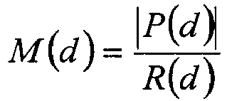
dans lequel la métrique de corrélation est obtenue par la formule suivante :
dans lequel l'énergie du symbole OFDM est obtenue par la formule suivante :
- Procédé selon la revendication 4, dans lequel le symbole de transmission est généré en insérant simultanément le CP dans une partie avant du symbole OFDM et en insérant le CS dans une partie arrière du symbole OFDM.
- Système de multiplexage par répartition orthogonale de la fréquence, OFDM, comprenant :un récepteur configuré pour recevoir, via un système OFDM configuré pour supporter des transmissions de signaux via des canaux radio qui montrent des retards multi-trajets, un symbole de transmission qui comporte un préfixe cyclique, CP, ou un suffixe cyclique, CS, inséré dans un symbole OFDM ; etun processeur coopérant avec le récepteur ;dans lequel une métrique de corrélation Pnew_CP(d) est obtenue par la formule suivante :

dans lequel l'énergie d'un symbole Rnew_CP(d) est obtenue par la formule suivante :
dans lequel une métrique de corrélation Pnew_CP(d) est obtenue par la formule suivante :
dans lequel l'énergie du symbole Rnew_CP(d) est obtenue par la formule suivante :
caractérisé en ce que
le processeur est configuré pour appliquer soit une première métrique de synchronisation soit une deuxième métrique de synchronisation au symbole de transmission reçu afin de détecter une synchronisation du symbole OFDM sur la base d'une valeur maximale de la première ou deuxième métrique de synchronisation,
dans lequel la première métrique de synchronisation est définie comme montré dans la formule suivante lorsque le symbole de transmission utilise le CP :
dans lequel la deuxième métrique de synchronisation est définie comme montré dans la formule suivante lorsque le symbole de transmission utilise le CS :
dans lequel MCP(d) et Mcs(d) sont définies comme montré dans la formule suivante :
- Système de multiplexage par répartition orthogonale de la fréquence, OFDM, comprenant :un générateur de symbole configuré pour insérer un préfixe cyclique, CP, et un suffixe cyclique, CS, dans un symbole OFDM et pour générer un symbole de transmission ;un émetteur configuré pour transmettre le symbole de transmission généré ;un récepteur configuré pour recevoir, via un système OFDM configuré pour supporter des transmissions de signaux via des canaux radio qui montrent des retards multi-trajets, ledit symbole de transmission ; etun processeur coopérant avec le récepteur ;caractérisé en ce que
le processeur est configuré pour appliquer une métrique de synchronisation particulière au symbole de transmission reçu afin de détecter une synchronisation du symbole OFDM sur la base d'une valeur maximale de la métrique de synchronisation,
dans lequel la métrique de synchronisation est définie par la formule suivante :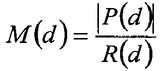
dans lequel la métrique de corrélation est obtenue par la formule suivante :
dans lequel l'énergie du symbole OFDM est obtenue par la formule suivante :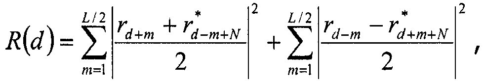
Applications Claiming Priority (3)
| Application Number | Priority Date | Filing Date | Title |
|---|---|---|---|
| KR1020040064541A KR20060016183A (ko) | 2004-08-17 | 2004-08-17 | 직교 주파수 분할 다중화 방식의 심볼 구성 및 동기 획득방법 |
| KR1020040064543A KR20060016185A (ko) | 2004-08-17 | 2004-08-17 | 직교 주파수 분할 다중전송 방식의 심볼 동기 획득 방법 |
| PCT/KR2005/002693 WO2006019255A1 (fr) | 2004-08-17 | 2005-08-17 | Methode pour detecter une synchronisation de symboles mrof dans un systeme mrof |
Publications (3)
| Publication Number | Publication Date |
|---|---|
| EP1779570A1 EP1779570A1 (fr) | 2007-05-02 |
| EP1779570A4 EP1779570A4 (fr) | 2011-03-23 |
| EP1779570B1 true EP1779570B1 (fr) | 2016-11-09 |
Family
ID=35907623
Family Applications (1)
| Application Number | Title | Priority Date | Filing Date |
|---|---|---|---|
| EP05780550.9A Expired - Lifetime EP1779570B1 (fr) | 2004-08-17 | 2005-08-17 | Methode pour detecter une synchronisation de symboles mrof dans un systeme mrof |
Country Status (4)
| Country | Link |
|---|---|
| US (1) | US7848436B2 (fr) |
| EP (1) | EP1779570B1 (fr) |
| JP (1) | JP4388979B2 (fr) |
| WO (1) | WO2006019255A1 (fr) |
Families Citing this family (11)
| Publication number | Priority date | Publication date | Assignee | Title |
|---|---|---|---|---|
| JP2008005389A (ja) * | 2006-06-26 | 2008-01-10 | Hitachi Ltd | 通信方法および通信装置 |
| CN101325569B (zh) * | 2007-06-15 | 2013-09-04 | 安捷伦科技有限公司 | 通信系统中的鲁棒信道估计 |
| CN101374131B (zh) * | 2007-08-20 | 2013-01-30 | 株式会社Ntt都科摩 | 定时同步方法及装置、前导符号的生成方法和装置 |
| US7809046B2 (en) * | 2007-10-03 | 2010-10-05 | Agere Systems Inc. | Timing-offset estimation in modulated signals using weighted correlation values |
| GB2463508B (en) * | 2008-09-16 | 2011-04-13 | Toshiba Res Europ Ltd | Wireless communications apparatus |
| US8194799B2 (en) * | 2009-03-30 | 2012-06-05 | King Fahd University of Pertroleum & Minerals | Cyclic prefix-based enhanced data recovery method |
| US8451957B2 (en) * | 2009-04-09 | 2013-05-28 | Hong Kong Applied Science And Technology Research Institute Co., Ltd. | System and method for time synchronization of OFDM-based communications |
| KR101975551B1 (ko) * | 2014-04-16 | 2019-08-28 | 상하이 내셔널 엔지니어링 리서치 센터 오브 디지털 텔레비전 컴퍼니, 리미티드 | 프리앰블 심볼의 생성 및 수신방법과 주파수 영역 심볼의 생성방법 및 장치 |
| US10103792B2 (en) * | 2016-01-14 | 2018-10-16 | Intel Corporation | Apparatus, system and method of communicating a multiple-input-multiple-output (MIMO) transmission |
| CN112583752B (zh) | 2019-09-29 | 2022-10-11 | 华为技术有限公司 | 一种基于卫星通信的信号传输方法及设备 |
| TR202007096A1 (tr) | 2020-05-06 | 2021-11-22 | Aselsan Elektronik Sanayi Ve Tic A S | Nedensel Olmayan Kanal Etkilerinin Azaltılması ve Telafi Edilmesi için Düşük Karmaşıklı Yöntem |
Family Cites Families (6)
| Publication number | Priority date | Publication date | Assignee | Title |
|---|---|---|---|---|
| US6618452B1 (en) * | 1998-06-08 | 2003-09-09 | Telefonaktiebolaget Lm Ericsson (Publ) | Burst carrier frequency synchronization and iterative frequency-domain frame synchronization for OFDM |
| JP3882479B2 (ja) | 2000-08-01 | 2007-02-14 | コクヨ株式会社 | プロジェクト活動支援システム |
| JP4341176B2 (ja) | 2000-12-08 | 2009-10-07 | ソニー株式会社 | 受信同期装置およびそれを用いた復調装置 |
| ES2188370B1 (es) * | 2001-05-21 | 2004-10-16 | Diseño De Sistemas En Silicio, S.A. | Procedimiento para la sincronizacion en el enlace descendente de multiples usuarios en un sistema de transmision punto a multipunto con modulacion ofdm. |
| KR20040011653A (ko) | 2002-07-29 | 2004-02-11 | 삼성전자주식회사 | 채널 특성에 적응적인 직교 주파수 분할 다중 통신 방법및 장치 |
| KR100606105B1 (ko) * | 2003-07-04 | 2006-07-28 | 삼성전자주식회사 | 다중 접속 방식을 사용하는 이동 통신 시스템의 셀 탐색장치 및 방법 |
-
2005
- 2005-08-17 JP JP2007527047A patent/JP4388979B2/ja not_active Expired - Fee Related
- 2005-08-17 EP EP05780550.9A patent/EP1779570B1/fr not_active Expired - Lifetime
- 2005-08-17 WO PCT/KR2005/002693 patent/WO2006019255A1/fr not_active Ceased
- 2005-08-17 US US11/573,687 patent/US7848436B2/en not_active Expired - Fee Related
Non-Patent Citations (1)
| Title |
|---|
| None * |
Also Published As
| Publication number | Publication date |
|---|---|
| US7848436B2 (en) | 2010-12-07 |
| WO2006019255A1 (fr) | 2006-02-23 |
| JP2008510419A (ja) | 2008-04-03 |
| EP1779570A4 (fr) | 2011-03-23 |
| JP4388979B2 (ja) | 2009-12-24 |
| EP1779570A1 (fr) | 2007-05-02 |
| US20070268974A1 (en) | 2007-11-22 |
Similar Documents
| Publication | Publication Date | Title |
|---|---|---|
| US10257011B2 (en) | Preamble configuring method in the wireless LAN system, and a method for a frame synchronization | |
| US7426175B2 (en) | Method and apparatus for pilot signal transmission | |
| US7336600B2 (en) | Cell search method for orthogonal frequency division multiplexing based cellular communication system | |
| EP1164733A1 (fr) | Procede de construction de canaux et station de base utilisant le procede | |
| KR20120063033A (ko) | 무선 통신 시스템에서 프리앰블 전송 방법 및 장치 | |
| US20050084035A1 (en) | Apparatus and method for transmitting and receiving a pilot signal in a communication system using a multi-carrier modulation scheme | |
| US10135654B2 (en) | Method and apparatus for generating code sequence in a communication system | |
| US8223858B2 (en) | Time synchronization method and frequency offset estimation method using the same in OFDM network | |
| EP1779570B1 (fr) | Methode pour detecter une synchronisation de symboles mrof dans un systeme mrof | |
| Zhou et al. | OFDMA initial ranging for IEEE 802.16 e based on time-domain and frequency-domain approaches | |
| US20100266078A1 (en) | Radio communication device, and reception quality estimation method | |
| KR100729726B1 (ko) | 직교 주파수 분할 다중화 방식의 통신 시스템의 타이밍획득 및 반송파 주파수 오차 추정 장치 및 방법 | |
| CN1983860A (zh) | 同步信号的发送方法及发送设备 | |
| KR100723634B1 (ko) | Ofdm 시스템에서 pn 수열을 이용한 프리엠블 수열생성 방법과, 시간 동기 및 주파수옵셋 추정 방법 | |
| US8223865B2 (en) | Method for the blind estimation of OFDM signal parameters by adapted filtering | |
| CN101006669B (zh) | 在正交频分多路复用系统中检测正交频分多路复用码元定时的方法 | |
| Priotti | Frequency synchronization of MIMO OFDM systems with frequency-selective weighting | |
| KR101342801B1 (ko) | 이동통신 시스템에서 코드 확장을 이용한 채널 추정 장치 및 방법 |
Legal Events
| Date | Code | Title | Description |
|---|---|---|---|
| PUAI | Public reference made under article 153(3) epc to a published international application that has entered the european phase |
Free format text: ORIGINAL CODE: 0009012 |
|
| 17P | Request for examination filed |
Effective date: 20070213 |
|
| AK | Designated contracting states |
Kind code of ref document: A1 Designated state(s): AT BE BG CH CY CZ DE DK EE ES FI FR GB GR HU IE IS IT LI LT LU LV MC NL PL PT RO SE SI SK TR |
|
| RIN1 | Information on inventor provided before grant (corrected) |
Inventor name: CHUN, JIN-YOUNG Inventor name: IHM, BIN-CHUL Inventor name: JIN, YONG-SUK |
|
| DAX | Request for extension of the european patent (deleted) | ||
| RAP1 | Party data changed (applicant data changed or rights of an application transferred) |
Owner name: LG ELECTRONICS INC. |
|
| A4 | Supplementary search report drawn up and despatched |
Effective date: 20110218 |
|
| GRAP | Despatch of communication of intention to grant a patent |
Free format text: ORIGINAL CODE: EPIDOSNIGR1 |
|
| INTG | Intention to grant announced |
Effective date: 20160524 |
|
| GRAS | Grant fee paid |
Free format text: ORIGINAL CODE: EPIDOSNIGR3 |
|
| GRAA | (expected) grant |
Free format text: ORIGINAL CODE: 0009210 |
|
| AK | Designated contracting states |
Kind code of ref document: B1 Designated state(s): AT BE BG CH CY CZ DE DK EE ES FI FR GB GR HU IE IS IT LI LT LU LV MC NL PL PT RO SE SI SK TR |
|
| REG | Reference to a national code |
Ref country code: GB Ref legal event code: FG4D |
|
| RIN1 | Information on inventor provided before grant (corrected) |
Inventor name: IHM, BIN-CHUL Inventor name: CHUN, JIN-YOUNG Inventor name: JIN, YONG-SUK |
|
| REG | Reference to a national code |
Ref country code: AT Ref legal event code: REF Ref document number: 844782 Country of ref document: AT Kind code of ref document: T Effective date: 20161115 Ref country code: CH Ref legal event code: EP |
|
| REG | Reference to a national code |
Ref country code: IE Ref legal event code: FG4D |
|
| REG | Reference to a national code |
Ref country code: DE Ref legal event code: R096 Ref document number: 602005050650 Country of ref document: DE |
|
| PG25 | Lapsed in a contracting state [announced via postgrant information from national office to epo] |
Ref country code: LV Free format text: LAPSE BECAUSE OF FAILURE TO SUBMIT A TRANSLATION OF THE DESCRIPTION OR TO PAY THE FEE WITHIN THE PRESCRIBED TIME-LIMIT Effective date: 20161109 |
|
| REG | Reference to a national code |
Ref country code: LT Ref legal event code: MG4D |
|
| REG | Reference to a national code |
Ref country code: NL Ref legal event code: MP Effective date: 20161109 |
|
| REG | Reference to a national code |
Ref country code: AT Ref legal event code: MK05 Ref document number: 844782 Country of ref document: AT Kind code of ref document: T Effective date: 20161109 |
|
| PG25 | Lapsed in a contracting state [announced via postgrant information from national office to epo] |
Ref country code: GR Free format text: LAPSE BECAUSE OF FAILURE TO SUBMIT A TRANSLATION OF THE DESCRIPTION OR TO PAY THE FEE WITHIN THE PRESCRIBED TIME-LIMIT Effective date: 20170210 Ref country code: LT Free format text: LAPSE BECAUSE OF FAILURE TO SUBMIT A TRANSLATION OF THE DESCRIPTION OR TO PAY THE FEE WITHIN THE PRESCRIBED TIME-LIMIT Effective date: 20161109 Ref country code: NL Free format text: LAPSE BECAUSE OF FAILURE TO SUBMIT A TRANSLATION OF THE DESCRIPTION OR TO PAY THE FEE WITHIN THE PRESCRIBED TIME-LIMIT Effective date: 20161109 Ref country code: SE Free format text: LAPSE BECAUSE OF FAILURE TO SUBMIT A TRANSLATION OF THE DESCRIPTION OR TO PAY THE FEE WITHIN THE PRESCRIBED TIME-LIMIT Effective date: 20161109 |
|
| PG25 | Lapsed in a contracting state [announced via postgrant information from national office to epo] |
Ref country code: PT Free format text: LAPSE BECAUSE OF FAILURE TO SUBMIT A TRANSLATION OF THE DESCRIPTION OR TO PAY THE FEE WITHIN THE PRESCRIBED TIME-LIMIT Effective date: 20170309 Ref country code: IS Free format text: LAPSE BECAUSE OF FAILURE TO SUBMIT A TRANSLATION OF THE DESCRIPTION OR TO PAY THE FEE WITHIN THE PRESCRIBED TIME-LIMIT Effective date: 20170309 Ref country code: PL Free format text: LAPSE BECAUSE OF FAILURE TO SUBMIT A TRANSLATION OF THE DESCRIPTION OR TO PAY THE FEE WITHIN THE PRESCRIBED TIME-LIMIT Effective date: 20161109 Ref country code: AT Free format text: LAPSE BECAUSE OF FAILURE TO SUBMIT A TRANSLATION OF THE DESCRIPTION OR TO PAY THE FEE WITHIN THE PRESCRIBED TIME-LIMIT Effective date: 20161109 Ref country code: ES Free format text: LAPSE BECAUSE OF FAILURE TO SUBMIT A TRANSLATION OF THE DESCRIPTION OR TO PAY THE FEE WITHIN THE PRESCRIBED TIME-LIMIT Effective date: 20161109 Ref country code: FI Free format text: LAPSE BECAUSE OF FAILURE TO SUBMIT A TRANSLATION OF THE DESCRIPTION OR TO PAY THE FEE WITHIN THE PRESCRIBED TIME-LIMIT Effective date: 20161109 |
|
| PG25 | Lapsed in a contracting state [announced via postgrant information from national office to epo] |
Ref country code: CZ Free format text: LAPSE BECAUSE OF FAILURE TO SUBMIT A TRANSLATION OF THE DESCRIPTION OR TO PAY THE FEE WITHIN THE PRESCRIBED TIME-LIMIT Effective date: 20161109 Ref country code: RO Free format text: LAPSE BECAUSE OF FAILURE TO SUBMIT A TRANSLATION OF THE DESCRIPTION OR TO PAY THE FEE WITHIN THE PRESCRIBED TIME-LIMIT Effective date: 20161109 Ref country code: SK Free format text: LAPSE BECAUSE OF FAILURE TO SUBMIT A TRANSLATION OF THE DESCRIPTION OR TO PAY THE FEE WITHIN THE PRESCRIBED TIME-LIMIT Effective date: 20161109 Ref country code: DK Free format text: LAPSE BECAUSE OF FAILURE TO SUBMIT A TRANSLATION OF THE DESCRIPTION OR TO PAY THE FEE WITHIN THE PRESCRIBED TIME-LIMIT Effective date: 20161109 Ref country code: EE Free format text: LAPSE BECAUSE OF FAILURE TO SUBMIT A TRANSLATION OF THE DESCRIPTION OR TO PAY THE FEE WITHIN THE PRESCRIBED TIME-LIMIT Effective date: 20161109 |
|
| REG | Reference to a national code |
Ref country code: DE Ref legal event code: R097 Ref document number: 602005050650 Country of ref document: DE |
|
| PG25 | Lapsed in a contracting state [announced via postgrant information from national office to epo] |
Ref country code: IT Free format text: LAPSE BECAUSE OF FAILURE TO SUBMIT A TRANSLATION OF THE DESCRIPTION OR TO PAY THE FEE WITHIN THE PRESCRIBED TIME-LIMIT Effective date: 20161109 Ref country code: BG Free format text: LAPSE BECAUSE OF FAILURE TO SUBMIT A TRANSLATION OF THE DESCRIPTION OR TO PAY THE FEE WITHIN THE PRESCRIBED TIME-LIMIT Effective date: 20170209 Ref country code: BE Free format text: LAPSE BECAUSE OF FAILURE TO SUBMIT A TRANSLATION OF THE DESCRIPTION OR TO PAY THE FEE WITHIN THE PRESCRIBED TIME-LIMIT Effective date: 20161109 |
|
| PLBE | No opposition filed within time limit |
Free format text: ORIGINAL CODE: 0009261 |
|
| STAA | Information on the status of an ep patent application or granted ep patent |
Free format text: STATUS: NO OPPOSITION FILED WITHIN TIME LIMIT |
|
| 26N | No opposition filed |
Effective date: 20170810 |
|
| PGFP | Annual fee paid to national office [announced via postgrant information from national office to epo] |
Ref country code: DE Payment date: 20170705 Year of fee payment: 13 |
|
| PG25 | Lapsed in a contracting state [announced via postgrant information from national office to epo] |
Ref country code: SI Free format text: LAPSE BECAUSE OF FAILURE TO SUBMIT A TRANSLATION OF THE DESCRIPTION OR TO PAY THE FEE WITHIN THE PRESCRIBED TIME-LIMIT Effective date: 20161109 |
|
| REG | Reference to a national code |
Ref country code: CH Ref legal event code: PL |
|
| PG25 | Lapsed in a contracting state [announced via postgrant information from national office to epo] |
Ref country code: MC Free format text: LAPSE BECAUSE OF FAILURE TO SUBMIT A TRANSLATION OF THE DESCRIPTION OR TO PAY THE FEE WITHIN THE PRESCRIBED TIME-LIMIT Effective date: 20161109 |
|
| GBPC | Gb: european patent ceased through non-payment of renewal fee |
Effective date: 20170817 |
|
| PG25 | Lapsed in a contracting state [announced via postgrant information from national office to epo] |
Ref country code: CH Free format text: LAPSE BECAUSE OF NON-PAYMENT OF DUE FEES Effective date: 20170831 Ref country code: LI Free format text: LAPSE BECAUSE OF NON-PAYMENT OF DUE FEES Effective date: 20170831 |
|
| REG | Reference to a national code |
Ref country code: FR Ref legal event code: ST Effective date: 20180430 |
|
| REG | Reference to a national code |
Ref country code: IE Ref legal event code: MM4A |
|
| PG25 | Lapsed in a contracting state [announced via postgrant information from national office to epo] |
Ref country code: LU Free format text: LAPSE BECAUSE OF NON-PAYMENT OF DUE FEES Effective date: 20170817 |
|
| PG25 | Lapsed in a contracting state [announced via postgrant information from national office to epo] |
Ref country code: GB Free format text: LAPSE BECAUSE OF NON-PAYMENT OF DUE FEES Effective date: 20170817 Ref country code: IE Free format text: LAPSE BECAUSE OF NON-PAYMENT OF DUE FEES Effective date: 20170817 |
|
| PG25 | Lapsed in a contracting state [announced via postgrant information from national office to epo] |
Ref country code: FR Free format text: LAPSE BECAUSE OF NON-PAYMENT OF DUE FEES Effective date: 20170831 |
|
| REG | Reference to a national code |
Ref country code: DE Ref legal event code: R119 Ref document number: 602005050650 Country of ref document: DE |
|
| PG25 | Lapsed in a contracting state [announced via postgrant information from national office to epo] |
Ref country code: HU Free format text: LAPSE BECAUSE OF FAILURE TO SUBMIT A TRANSLATION OF THE DESCRIPTION OR TO PAY THE FEE WITHIN THE PRESCRIBED TIME-LIMIT; INVALID AB INITIO Effective date: 20050817 |
|
| PG25 | Lapsed in a contracting state [announced via postgrant information from national office to epo] |
Ref country code: DE Free format text: LAPSE BECAUSE OF NON-PAYMENT OF DUE FEES Effective date: 20190301 |
|
| PG25 | Lapsed in a contracting state [announced via postgrant information from national office to epo] |
Ref country code: CY Free format text: LAPSE BECAUSE OF NON-PAYMENT OF DUE FEES Effective date: 20161109 |
|
| PG25 | Lapsed in a contracting state [announced via postgrant information from national office to epo] |
Ref country code: TR Free format text: LAPSE BECAUSE OF FAILURE TO SUBMIT A TRANSLATION OF THE DESCRIPTION OR TO PAY THE FEE WITHIN THE PRESCRIBED TIME-LIMIT Effective date: 20161109 |