EP1777400A2 - Procédé pour tester une soupape - Google Patents
Procédé pour tester une soupape Download PDFInfo
- Publication number
- EP1777400A2 EP1777400A2 EP06120658A EP06120658A EP1777400A2 EP 1777400 A2 EP1777400 A2 EP 1777400A2 EP 06120658 A EP06120658 A EP 06120658A EP 06120658 A EP06120658 A EP 06120658A EP 1777400 A2 EP1777400 A2 EP 1777400A2
- Authority
- EP
- European Patent Office
- Prior art keywords
- valve
- current
- moving average
- error
- determined
- Prior art date
- Legal status (The legal status is an assumption and is not a legal conclusion. Google has not performed a legal analysis and makes no representation as to the accuracy of the status listed.)
- Withdrawn
Links
Images


Classifications
-
- F—MECHANICAL ENGINEERING; LIGHTING; HEATING; WEAPONS; BLASTING
- F02—COMBUSTION ENGINES; HOT-GAS OR COMBUSTION-PRODUCT ENGINE PLANTS
- F02M—SUPPLYING COMBUSTION ENGINES IN GENERAL WITH COMBUSTIBLE MIXTURES OR CONSTITUENTS THEREOF
- F02M65/00—Testing fuel-injection apparatus, e.g. testing injection timing ; Cleaning of fuel-injection apparatus
-
- F—MECHANICAL ENGINEERING; LIGHTING; HEATING; WEAPONS; BLASTING
- F02—COMBUSTION ENGINES; HOT-GAS OR COMBUSTION-PRODUCT ENGINE PLANTS
- F02D—CONTROLLING COMBUSTION ENGINES
- F02D41/00—Electrical control of supply of combustible mixture or its constituents
- F02D41/20—Output circuits, e.g. for controlling currents in command coils
-
- F—MECHANICAL ENGINEERING; LIGHTING; HEATING; WEAPONS; BLASTING
- F02—COMBUSTION ENGINES; HOT-GAS OR COMBUSTION-PRODUCT ENGINE PLANTS
- F02D—CONTROLLING COMBUSTION ENGINES
- F02D41/00—Electrical control of supply of combustible mixture or its constituents
- F02D41/22—Safety or indicating devices for abnormal conditions
- F02D41/221—Safety or indicating devices for abnormal conditions relating to the failure of actuators or electrically driven elements
-
- F—MECHANICAL ENGINEERING; LIGHTING; HEATING; WEAPONS; BLASTING
- F02—COMBUSTION ENGINES; HOT-GAS OR COMBUSTION-PRODUCT ENGINE PLANTS
- F02D—CONTROLLING COMBUSTION ENGINES
- F02D41/00—Electrical control of supply of combustible mixture or its constituents
- F02D41/20—Output circuits, e.g. for controlling currents in command coils
- F02D2041/202—Output circuits, e.g. for controlling currents in command coils characterised by the control of the circuit
- F02D2041/2051—Output circuits, e.g. for controlling currents in command coils characterised by the control of the circuit using voltage control
-
- F—MECHANICAL ENGINEERING; LIGHTING; HEATING; WEAPONS; BLASTING
- F02—COMBUSTION ENGINES; HOT-GAS OR COMBUSTION-PRODUCT ENGINE PLANTS
- F02D—CONTROLLING COMBUSTION ENGINES
- F02D41/00—Electrical control of supply of combustible mixture or its constituents
- F02D41/20—Output circuits, e.g. for controlling currents in command coils
- F02D2041/202—Output circuits, e.g. for controlling currents in command coils characterised by the control of the circuit
- F02D2041/2055—Output circuits, e.g. for controlling currents in command coils characterised by the control of the circuit with means for determining actual opening or closing time
-
- F—MECHANICAL ENGINEERING; LIGHTING; HEATING; WEAPONS; BLASTING
- F02—COMBUSTION ENGINES; HOT-GAS OR COMBUSTION-PRODUCT ENGINE PLANTS
- F02M—SUPPLYING COMBUSTION ENGINES IN GENERAL WITH COMBUSTIBLE MIXTURES OR CONSTITUENTS THEREOF
- F02M63/00—Other fuel-injection apparatus having pertinent characteristics not provided for in groups F02M39/00 - F02M57/00 or F02M67/00; Details, component parts, or accessories of fuel-injection apparatus, not provided for in, or of interest apart from, the apparatus of groups F02M39/00 - F02M61/00 or F02M67/00; Combination of fuel pump with other devices, e.g. lubricating oil pump
- F02M63/0012—Valves
- F02M63/0014—Valves characterised by the valve actuating means
- F02M63/0015—Valves characterised by the valve actuating means electrical, e.g. using solenoid
-
- F—MECHANICAL ENGINEERING; LIGHTING; HEATING; WEAPONS; BLASTING
- F02—COMBUSTION ENGINES; HOT-GAS OR COMBUSTION-PRODUCT ENGINE PLANTS
- F02M—SUPPLYING COMBUSTION ENGINES IN GENERAL WITH COMBUSTIBLE MIXTURES OR CONSTITUENTS THEREOF
- F02M63/00—Other fuel-injection apparatus having pertinent characteristics not provided for in groups F02M39/00 - F02M57/00 or F02M67/00; Details, component parts, or accessories of fuel-injection apparatus, not provided for in, or of interest apart from, the apparatus of groups F02M39/00 - F02M61/00 or F02M67/00; Combination of fuel pump with other devices, e.g. lubricating oil pump
- F02M63/0012—Valves
- F02M63/0031—Valves characterized by the type of valves, e.g. special valve member details, valve seat details, valve housing details
- F02M63/0047—Four-way valves or valves with more than four ways
-
- Y—GENERAL TAGGING OF NEW TECHNOLOGICAL DEVELOPMENTS; GENERAL TAGGING OF CROSS-SECTIONAL TECHNOLOGIES SPANNING OVER SEVERAL SECTIONS OF THE IPC; TECHNICAL SUBJECTS COVERED BY FORMER USPC CROSS-REFERENCE ART COLLECTIONS [XRACs] AND DIGESTS
- Y02—TECHNOLOGIES OR APPLICATIONS FOR MITIGATION OR ADAPTATION AGAINST CLIMATE CHANGE
- Y02T—CLIMATE CHANGE MITIGATION TECHNOLOGIES RELATED TO TRANSPORTATION
- Y02T10/00—Road transport of goods or passengers
- Y02T10/10—Internal combustion engine [ICE] based vehicles
- Y02T10/40—Engine management systems
Definitions
- the invention relates to a method for checking a valve, in particular a magnetically bistable solenoid valve for an injection valve of an internal combustion engine in a motor vehicle.
- the object of the invention is to provide a method for checking a valve which is simple and reliable.
- the invention is characterized by a method for checking a valve with a valve piston, which is movable depending on a control of the valve for opening and closing the valve.
- the valve comprises at least one coil and at least one magnetized component.
- the valve is configured such that an induction voltage is induced in the at least one coil by moving the valve piston in the valve by a magnetic field generated by the magnetized component.
- a reference time is detected that is representative of a beginning of a current drive cycle of the valve. In the current drive cycle, a time is determined depending on a characteristic curve of the induction voltage, which is representative of an end of a movement process of the valve piston in the valve.
- a current switching time is determined depending on the time and the reference time.
- At least one error condition is determined depending on the Switching period. An error is detected if the at least one error condition is fulfilled.
- the advantage is that, depending on the switching time, the error of the valve can be detected easily and reliably. In particular, a mechanical malfunction of the valve, e.g. by hydraulic bonding of the valve piston, reliably recognizable. If the valve is, for example, part of an injection valve of an internal combustion engine of a motor vehicle, then the fault of the valve can lead to increased pollutant emission. By detecting the error, it is possible to signal the error to the driver of the vehicle, so that the error can be corrected in a workshop.
- the at least one error condition is fulfilled if the switching time duration is greater than a predetermined first threshold value.
- a current moving average is determined as a function of the current switching time duration and a predetermined number of the respective switching time duration of preceding drive cycles.
- the at least one error condition is met when an amount of a difference of the current shift time period and the current moving average value or a moving average value determined for a preceding drive cycle is greater than a predetermined second threshold value.
- the current moving average is determined as a function of the current switching time duration and the predetermined number of the respective switching time duration of preceding drive cycles.
- the current moving average is saved.
- a quantity representative of a current rate of change of the moving average is determined.
- the at least one error condition is met when the magnitude is greater than a predetermined third threshold.
- the error is detected in each case only if the at least one error condition is fulfilled within a predetermined maximum error interval for at least one predetermined number of errors.
- the method is performed when predetermined operating conditions prevail of the valve.
- the switching period or the moving average are corrected depending on currently prevailing operating conditions of the valve. This has the advantage that switching time durations and moving average values determined under different operating conditions can be compared to one another in a good manner and the checking of the valve is thus particularly reliable.
- a valve e.g. a control valve for an injection valve for an internal combustion engine in a motor vehicle, comprising a valve housing 1, which has a recess in which a valve piston 2 is arranged axially movable ( Figure 1).
- the valve has an inlet 3 and two outlets 4, which are formed in the valve housing 1. Furthermore, 1 outflows 5 are formed in the valve housing.
- the inlet 3 can be coupled, for example, to a fluid reservoir, not shown, from which the valve receives a fluid, e.g. Hydraulic oil or engine oil, can be supplied.
- the outlets 4 open, for example, in a control room, not shown, to the e.g. adjacent to a hydraulic ram, which is movable in response to a fluid pressure in the control chamber for opening and closing the injection valve.
- the inlet 3 is hydraulically coupled via grooves 8, which are formed in the valve piston 2 and the valve housing 1, with the outlets 4 or are the outlets 4 with the outflows 5 coupled. Through the outflows 5, the fluid can flow out of the control room.
- the valve has a first cap 6 and a second cap 7, each disposed at an axial end of the valve.
- the first cap 6 and the second cap 7 limit the stroke of the valve piston 2 in the valve housing 1.
- Adjacent to the first cap 6 is a first coil L1 and adjacent to the second cap 7, a second coil L2 is arranged.
- a suitable energizing the first coil L1 and the second coil L2 a magnetic field can be constructed so that the valve piston 2 is tightened by this and against the moved by the first cap 6 and the second cap 7 stroke limitation is moved.
- the first cap 6 and the second cap 7 are formed so that even after stopping energizing the first coil L1 and the second coil L2 by a corresponding magnetization of the first cap 6 and the second cap 7, a remanence magnetic field is maintained.
- the valve piston 2 can thus maintain its current position on the first cap 6 and the second cap 7 until the valve piston 2 is pulled by the energizing of the respective opposite coil to the associated cap.
- the valve thus forms a solenoid bistable solenoid valve.
- the valve can also be designed differently.
- Figure 2 shows a circuit arrangement which is designed for driving the valve.
- the circuit arrangement has a control device 9 which, for example, generates a pulse-width-modulated control signal, which is supplied to a first switch SW1.
- the first switch SW1 is electrically arranged between a positive potential of a battery voltage UBAT and a first terminal of the first coil L1.
- the battery voltage UBAT is for example about 24 volts.
- the first switch SW1 and the first terminal of the first coil L1 are coupled via a reverse-direction first diode D1 to a negative potential of the battery voltage UBAT, which is referred to as a ground potential GND.
- a second terminal of the first coil L1 is coupled to the ground potential GND via a second switch SW2.
- the second switch SW2 is provided for selecting the valve when further valves are controlled by the control device 9.
- the second port is the first one Coil L1 is coupled via a reverse-connected second diode D2 to the positive potential of the battery voltage UBAT.
- the first switch SW1, the second switch SW2, the first diode D1, and the second diode D2 are respectively provided for the second coil L2.
- the control device 9 is preferably designed to generate the pulse-width-modulated control signal correspondingly also for the second coil L2.
- the first coil L1 and the second coil L2 are preferably energized alternately so that the valve piston 2 is moved to the respective other axial position on the first cap 6 and the second cap 7.
- the respectively energized coil is used to detect the movement of the valve piston 2 in the valve housing 1.
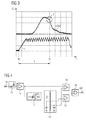
- an induction voltage UIND in the first coil L1 and in the second coil L2 ( Figure 3). This induction voltage UIND is particularly easy to detect in the respective de-energized coil.
- Figure 3 shows a diagram in which a profile of an electric current I through the first coil L1 and the second coil L2 is shown in the Bestromen.
- the energization of the respective coil begins at a reference time t0 by the switching on of the respective coil associated first switch SW1 and second switch SW2.
- the reference time t0 is representative of a beginning of a current drive cycle of the valve.
- the electric current I increases until a predetermined current is reached. Then, the current I by alternately turning on and off the first Switch SW1 held in a predetermined range.
- the induction voltage UIND is induced in the respective currentless coil.
- the induction voltage UIND shows a characteristic course in the form of a bend B.
- the kink B is caused by the end of the movement of the valve piston 2. Since the induction voltage UIND is not further induced after the time t1, it falls faster after the time t1 than before the first time t1. The end of the movement of the valve piston 2 can thus be detected by the detection of the buckling B in the course of the induction voltage UIND.
- the time t1 is representative of the end of the movement of the valve piston 2 in the valve.
- the current drive cycle is terminated by stopping the energization of the first coil L1 and the second coil L2.
- Figure 4 shows a block diagram of a device for detecting the end of the movement of the valve piston 2 in the valve.
- the device has an input IN, via which the device, the induction voltage UIND can be fed.
- a protection circuit 10 is provided on the input side of the device in order to protect the device from an excessive input voltage at the input IN and thus to prevent damage to the device.
- the protection circuit 10 is coupled to a buffer 11 on the output side of the buffer 11, the induction voltage UIND can be tapped.
- the buffer 11 is coupled to a differentiator 12, which forms a first derivative of the induction voltage UIND after the time and provides this on the output side. Further is in the apparatus, a reference generator 13 is provided which generates and specifies a predetermined induction voltage threshold and a predetermined derivative threshold.
- a first comparator 14 is provided for comparing the induction voltage UIND with the predetermined induction voltage threshold.
- a second comparator 15 is provided for comparing the first derivative of the induction voltage UIND with the predetermined derivative threshold.
- the first comparator 14 and the second comparator 15 are logically linked together via an AND gate 16.
- An output OUT of the device is formed by an output of the AND gate 16. At the output OUT, the detection of the end of the movement of the valve piston 2 is signaled when the induction voltage UIND is greater than the predetermined induction voltage threshold and the first derivative of the induction voltage UIND drops the predetermined derivative threshold.
- the signal at the output OUT e.g. an output pulse at or shortly after time t1 can be supplied, for example, to the control device 9, which is designed to control the valve in such a way that e.g. a predetermined amount of fuel is injected.
- a method corresponding to the block diagram may also be provided, e.g. in the form of a program executed by the controller 9.
- the bend B in the course of the induction voltage UIND can also be detected by a differently configured device or by another method.
- FIG. 5 shows a first flow chart of a first method for checking the valve.
- the first method starts in a step S1.
- the step S1 is preferably carried out at the beginning of the current drive cycle.
- the reference time t0 is detected.
- the step S3 is repeated until the end of the movement of the valve piston 2 has been detected or the repetition is canceled due to the exceeding of a predetermined maximum time since the start of the current drive cycle.
- a step S4 the time t1 is detected. Further, a current switching period T is determined depending on the time t1 and the reference time t0, for example, as a difference of the time t1 and the reference time t0.
- a step S5 it is checked whether a first error condition is fulfilled. The first error condition is satisfied when the switching period T is greater than a predetermined first threshold value THR1. If the first error condition is fulfilled, then in a step S6 the time t1 is stored as a first error time t_ERR1 and a first error number n1 is increased, for example by one.
- a step S7 it is checked whether the first number of errors n1 is greater than a predefined first maximum number of errors n1_max. If this condition is fulfilled, then a first error ERR1 of the valve is detected in a step S8 and the first method is ended in a step S11. If the condition is not met in step S7, then the first method is also ended in step S11.
- step S9 If the first error condition is not met in step S5, ie if the current switching time T is less than or equal to the predetermined first threshold value THR1, then it is checked in a step S9 whether a difference between the time t1 and the first error time t_ERR1 is greater than a predetermined one first maximum error interval T_ERR1.
- the predetermined first maximum error interval T_ERR1 is a time period in which the first error condition must be satisfied in step S5 for at least the predetermined first maximum number of errors n1_max in order to detect the error of the valve. Therefore, in a step S10, the first error number n1 is set to a neutral value, e.g.
- step S10 the difference of the time t1 and the first error time t_ERR1 is greater than the predetermined first maximum error interval T_ERR1.
- the first method is ended after step S10 in step S11.
- the first method is also ended in step S11 if the condition is not satisfied in step S9.
- FIG. 6 shows a second flow chart of a second method for checking the valve.
- the second process starts in a step S20 which is executed in accordance with the step S1 at the beginning of the current drive cycle.
- the reference time t0 is detected in the step S21.
- the step S22 according to the step S3, the end of the movement of the valve piston in the valve is detected.
- the time t1 and the switching time T are determined in accordance with the step S4.
- the switching period T is stored.
- a current moving average value m is determined as a function of the current switching time duration T and a predetermined number of the respectively stored switching time duration of preceding drive cycles. For example Approximately ten or twenty previous drive cycles are taken into account for determining the current moving average m.
- a step S26 it is checked whether a second error condition is fulfilled.
- the second error condition in step S26 is satisfied when an amount of a difference of the current shift time T and either the current moving average m, which includes the current shift time T, or a moving average determined for a preceding drive cycle, which is the current shift time T not greater than a predetermined second threshold THR2. If the second error condition is satisfied, then in a step S27 the time t1 is stored as a second error time t_ERR2 and a second error number n2 is increased, e.g. at one. In a step S28, it is checked whether the second error number n2 is greater than a predetermined second maximum error number n2_max. If this condition is met, then a second error ERR2 is detected in a step S29 and the second method is ended in a step S32. The second process is also terminated in step S32 if the condition is not satisfied in step S28.
- step S30 checks whether a difference of the time t1 and the second error time t_ERR2 is greater than a predetermined second maximum error interval T_ERR2. Is this condition satisfied, then in a step S31, the second error number n2 is set to a neutral value, for example to zero. The second process is ended in step S32. The second process is also terminated in step S32 if the condition is not satisfied in step S30.
- the second error ERR2 represents a fluctuation of the switching time T.
- the fluctuating switching time T can lead to corresponding fluctuations of the metered amount of fluid. In the internal combustion engine thereby pollutant emissions can be increased.
- FIG. 7 shows a third flow diagram of a third method for checking the valve.
- the third process starts in a step S40 which is executed in accordance with the step S1 or the step S20.
- step S40 is preferably performed less frequently than step S1 or step S20, e.g. only once in each hour of operation of the valve or once per operation of the valve, e.g. each at the start of operation of the valve.
- the reference time t0 is detected in accordance with the step S21.
- step S42 according to the step S22, the end of the movement of the valve spool 2 in the valve is detected.
- the time t1 and the switching time T are determined in accordance with the step S23.
- step S44 the switching period T is stored in accordance with step S24, and in step S45, the current moving average m is determined in accordance with step S25.
- a step S46 the current moving average m is stored.
- a step S47 it is checked whether a third error condition is satisfied.
- the third error condition is satisfied when a quantity representative of a current moving average rate of change is greater than a predetermined third threshold THR3.
- the size is determined depending on the current moving average m and at least one previously stored moving average.
- the mean values taken into account for determining the size are preferably random samples of the respective current moving average m, which are stored over longer periods of time, for example months or years or depending on the operating time duration of the valve.
- the third method uses the recognition that the switching time of the valve changes slowly due to wear, but accelerates the change when the failure of the valve is imminent.
- step S47 If the third error condition is satisfied in step S47, then a third error ERR3 is detected in a step S48 and the third method is ended in a step S49. The third method is also terminated in step S49 if the condition is not satisfied in step S47.
- the third method can also be extended such that the third error ERR3 is only detected if the third error condition is met within a further predetermined maximum error interval for at least one further predetermined number of errors.
- FIG. 8 shows a fourth flow chart of a fourth method for checking the valve.
- the fourth method comprises the first, second and third methods.
- the process starts in a step S60.
- a step S61 the first method is executed.
- a step S62 the second process is executed, and in a step S63, the third method performed.
- the fourth method is ended in a step S64 and, if appropriate, continued after a waiting period TW in the step S60.
- steps S2, S3 and S4 are preferably performed together for the first, second and third methods, so that the steps S21, S22 and S23 as well as the steps S41, S42 and S43 do not have to be executed again. Accordingly, steps S44 and S45 need not be executed again if steps S24 and S25 have already been executed.
- the first, second and third methods can each be carried out independently of the respective other two methods. Likewise, these methods can be performed in any combination. The order of execution can be chosen arbitrarily.
- the first, second, third or fourth methods are carried out when predetermined operating conditions of the valve prevail, e.g. at a given temperature.
- predetermined operating conditions of the valve e.g. at a given temperature.
- switching durations or moving average values determined in different drive cycles are particularly easy to compare with one another.
- the current shift time T or the current moving average m is corrected depending on currently prevailing operating conditions of the valve. This correction can for example be based on a reference temperature.
Applications Claiming Priority (1)
| Application Number | Priority Date | Filing Date | Title |
|---|---|---|---|
| DE102005050338A DE102005050338A1 (de) | 2005-10-20 | 2005-10-20 | Verfahren zum Überprüfen eines Ventils |
Publications (2)
| Publication Number | Publication Date |
|---|---|
| EP1777400A2 true EP1777400A2 (fr) | 2007-04-25 |
| EP1777400A3 EP1777400A3 (fr) | 2010-03-31 |
Family
ID=37682619
Family Applications (1)
| Application Number | Title | Priority Date | Filing Date |
|---|---|---|---|
| EP06120658A Withdrawn EP1777400A3 (fr) | 2005-10-20 | 2006-09-14 | Procédé pour tester une soupape |
Country Status (3)
| Country | Link |
|---|---|
| US (1) | US8019569B2 (fr) |
| EP (1) | EP1777400A3 (fr) |
| DE (1) | DE102005050338A1 (fr) |
Cited By (5)
| Publication number | Priority date | Publication date | Assignee | Title |
|---|---|---|---|---|
| WO2011003704A1 (fr) * | 2009-07-10 | 2011-01-13 | Continental Automotive Gmbh | Détermination du moment de fermeture dune soupape dinjection de carburant en fonction dune analyse de la tension de commande |
| EP2281113A2 (fr) * | 2008-05-17 | 2011-02-09 | Daimler AG | Dispositif de commande d'actionnement de soupape |
| WO2011134794A1 (fr) * | 2010-04-26 | 2011-11-03 | Continental Automotive Gmbh | Excitation électrique d'une soupape sur la base d'une connaissance du moment de fermeture de la soupape |
| DE102012200275A1 (de) | 2012-01-11 | 2013-07-11 | Continental Automotive Gmbh | Ermitteln eines Bewegungsverhaltens eines Kraftstoffinjektors basierend auf dem Bewegungsverhalten in einem eine Mehrfacheinspritzung aufweisenden modifizierten Betriebszustand |
| US20220196184A1 (en) * | 2020-12-21 | 2022-06-23 | Buerkert Werke Gmbh & Co. Kg | Method of diagnosing a valve, diagnosis module, and valve |
Families Citing this family (8)
| Publication number | Priority date | Publication date | Assignee | Title |
|---|---|---|---|---|
| DE102005044886B4 (de) * | 2005-09-20 | 2009-12-24 | Continental Automotive Gmbh | Vorrichtung und Verfahren zum Erkennen eines Endes einer Bewegung eines Ventilkolbens in einem Ventil |
| EP2268911B1 (fr) * | 2008-03-17 | 2017-01-04 | Husqvarna AB | Unite de distribution de carburant |
| RU2456469C2 (ru) * | 2008-03-17 | 2012-07-20 | Хускварна Аб | Блок подачи топлива |
| EP2728230A1 (fr) * | 2012-10-30 | 2014-05-07 | Danfoss A/S | Dispositif d'actionnement de soupape, en particulier pour une soupape de système de chauffage ou de refroidissement |
| DE102013017446A1 (de) * | 2013-10-22 | 2015-04-23 | Man Diesel & Turbo Se | Motorsteuergerät |
| CN103629176B (zh) * | 2013-11-11 | 2015-11-11 | 湖南中联重科智能技术有限公司 | 运动部件协同动作控制方法、装置及系统 |
| CN104775961A (zh) * | 2015-03-31 | 2015-07-15 | 苏州固基电子科技有限公司 | 一种用于电磁阀线路故障的故障检测电路 |
| US10968731B2 (en) * | 2016-11-21 | 2021-04-06 | Schlumberger Technology Corporation | System and method for monitoring a blowout preventer |
Citations (9)
| Publication number | Priority date | Publication date | Assignee | Title |
|---|---|---|---|---|
| DE3730523A1 (de) * | 1987-09-11 | 1989-03-30 | Bosch Gmbh Robert | Verfahren und einrichtung zur detektion der schaltzeiten von magnetventilen |
| DE3817770A1 (de) * | 1988-05-26 | 1989-11-30 | Daimler Benz Ag | Einrichtung zur getakteten ansteuerung eines elektromagnetischen ventils |
| DE3942836A1 (de) * | 1989-12-23 | 1991-06-27 | Daimler Benz Ag | Verfahren zur bewegungs- und lagezustandserkennung eines durch magnetische wechselwirkung zwischen zwei endpositionen beweglichen bauteiles eines induktiven elektrischen verbrauchers |
| DE4308811A1 (de) * | 1992-07-21 | 1994-01-27 | Bosch Gmbh Robert | Verfahren und Einrichtung zur Steuerung einer magnetventilgesteuerten Kraftstoffzumeßeinrichtung |
| EP1128049A2 (fr) * | 2000-02-23 | 2001-08-29 | Mazda Motor Corporation | Commande de pression de carburant pour un système d'injection à haute pression |
| EP1162360A2 (fr) * | 2000-06-08 | 2001-12-12 | Toyota Jidosha Kabushiki Kaisha | Dispositif d'identification de pannes de fonctionnement de moteur à combustion interne |
| US20030106365A1 (en) * | 2001-10-12 | 2003-06-12 | Honda Giken Kogyo Kabushiki Kaisha | Engine malfunction detection system |
| US20030229440A1 (en) * | 2002-05-14 | 2003-12-11 | Yasuhiro Tanaka | Control apparatus for vehicle |
| US20050030691A1 (en) * | 2003-07-21 | 2005-02-10 | Siemens Vdo Automotive Corporation | Power supply and control method for injector driver module |
Family Cites Families (16)
| Publication number | Priority date | Publication date | Assignee | Title |
|---|---|---|---|---|
| US4394742A (en) * | 1980-10-31 | 1983-07-19 | Fmc Corporation | Engine generated waveform analyzer |
| DE3244940A1 (de) * | 1982-12-04 | 1984-06-07 | Robert Bosch Gmbh, 7000 Stuttgart | Verfahren und schaltungsanordnung zur auswertung von ausgangssignalen eines an einer brennkraftmaschine befindlichen messwertaufnehmers |
| US5535621A (en) * | 1994-03-02 | 1996-07-16 | Ford Motor Company | On-board detection of fuel injector malfunction |
| US5720261A (en) * | 1994-12-01 | 1998-02-24 | Oded E. Sturman | Valve controller systems and methods and fuel injection systems utilizing the same |
| DE19726225B4 (de) * | 1997-06-20 | 2008-02-07 | Robert Bosch Gmbh | Anordnung mit einem oder mehreren hydraulischen Stellgliedern |
| JP3527857B2 (ja) * | 1998-12-25 | 2004-05-17 | 株式会社日立製作所 | 燃料噴射装置及び内燃機関 |
| DE10024685A1 (de) * | 2000-05-18 | 2001-11-22 | Zeiss Carl Jena Gmbh | Anordnung zur konfokalen Autofokussierung |
| DE10112639A1 (de) * | 2001-03-16 | 2002-09-19 | Zeiss Carl Jena Gmbh | Mikroskop mit Autofokussiereinrichtung |
| DE10127284A1 (de) * | 2001-06-05 | 2002-12-12 | Zeiss Carl Jena Gmbh | Autofokussiereinrichtung für ein optisches Gerät |
| JP4067384B2 (ja) * | 2002-10-30 | 2008-03-26 | 株式会社ミクニ | 燃料噴射方法 |
| US6754604B2 (en) * | 2002-11-01 | 2004-06-22 | Snap-On Incorporated | Method and apparatus for diagnosing fuel injectors |
| JP2004183550A (ja) * | 2002-12-03 | 2004-07-02 | Isuzu Motors Ltd | コモンレール圧検出値のフィルタ処理装置及びコモンレール式燃料噴射制御装置 |
| WO2004088190A1 (fr) * | 2003-04-01 | 2004-10-14 | Monatec Pty Ltd | Procede et dispositif de controle de soupapes |
| DE10319182B4 (de) * | 2003-04-29 | 2008-06-12 | Carl Zeiss Jena Gmbh | Verfahren und Anordnung zur Bestimmung der Fokusposition bei der Abbildung einer Probe |
| JP2005249697A (ja) * | 2004-03-08 | 2005-09-15 | Jeol Ltd | ノズル詰まり検出方法および分析装置 |
| BRPI0403883B1 (pt) * | 2004-09-10 | 2015-09-29 | Docol Metais Sanitários Ltda | Válvula solenóide e conjunto solenóide |
-
2005
- 2005-10-20 DE DE102005050338A patent/DE102005050338A1/de not_active Withdrawn
-
2006
- 2006-09-14 EP EP06120658A patent/EP1777400A3/fr not_active Withdrawn
- 2006-10-20 US US11/584,269 patent/US8019569B2/en not_active Expired - Fee Related
Patent Citations (9)
| Publication number | Priority date | Publication date | Assignee | Title |
|---|---|---|---|---|
| DE3730523A1 (de) * | 1987-09-11 | 1989-03-30 | Bosch Gmbh Robert | Verfahren und einrichtung zur detektion der schaltzeiten von magnetventilen |
| DE3817770A1 (de) * | 1988-05-26 | 1989-11-30 | Daimler Benz Ag | Einrichtung zur getakteten ansteuerung eines elektromagnetischen ventils |
| DE3942836A1 (de) * | 1989-12-23 | 1991-06-27 | Daimler Benz Ag | Verfahren zur bewegungs- und lagezustandserkennung eines durch magnetische wechselwirkung zwischen zwei endpositionen beweglichen bauteiles eines induktiven elektrischen verbrauchers |
| DE4308811A1 (de) * | 1992-07-21 | 1994-01-27 | Bosch Gmbh Robert | Verfahren und Einrichtung zur Steuerung einer magnetventilgesteuerten Kraftstoffzumeßeinrichtung |
| EP1128049A2 (fr) * | 2000-02-23 | 2001-08-29 | Mazda Motor Corporation | Commande de pression de carburant pour un système d'injection à haute pression |
| EP1162360A2 (fr) * | 2000-06-08 | 2001-12-12 | Toyota Jidosha Kabushiki Kaisha | Dispositif d'identification de pannes de fonctionnement de moteur à combustion interne |
| US20030106365A1 (en) * | 2001-10-12 | 2003-06-12 | Honda Giken Kogyo Kabushiki Kaisha | Engine malfunction detection system |
| US20030229440A1 (en) * | 2002-05-14 | 2003-12-11 | Yasuhiro Tanaka | Control apparatus for vehicle |
| US20050030691A1 (en) * | 2003-07-21 | 2005-02-10 | Siemens Vdo Automotive Corporation | Power supply and control method for injector driver module |
Cited By (8)
| Publication number | Priority date | Publication date | Assignee | Title |
|---|---|---|---|---|
| EP2281113A2 (fr) * | 2008-05-17 | 2011-02-09 | Daimler AG | Dispositif de commande d'actionnement de soupape |
| WO2011003704A1 (fr) * | 2009-07-10 | 2011-01-13 | Continental Automotive Gmbh | Détermination du moment de fermeture dune soupape dinjection de carburant en fonction dune analyse de la tension de commande |
| US8935114B2 (en) | 2009-07-10 | 2015-01-13 | Continental Automotive Gmbh | Determining the closing time of a fuel injection valve based on evaluating the actuation voltage |
| WO2011134794A1 (fr) * | 2010-04-26 | 2011-11-03 | Continental Automotive Gmbh | Excitation électrique d'une soupape sur la base d'une connaissance du moment de fermeture de la soupape |
| US8887560B2 (en) | 2010-04-26 | 2014-11-18 | Continental Automotive Gmbh | Electric actuation of a valve based on knowledge of the closing time of the valve |
| DE102012200275A1 (de) | 2012-01-11 | 2013-07-11 | Continental Automotive Gmbh | Ermitteln eines Bewegungsverhaltens eines Kraftstoffinjektors basierend auf dem Bewegungsverhalten in einem eine Mehrfacheinspritzung aufweisenden modifizierten Betriebszustand |
| DE102012200275B4 (de) * | 2012-01-11 | 2016-10-20 | Continental Automotive Gmbh | Ermitteln eines Bewegungsverhaltens eines Kraftstoffinjektors basierend auf dem Bewegungsverhalten in einem eine Mehrfacheinspritzung aufweisenden modifizierten Betriebszustand |
| US20220196184A1 (en) * | 2020-12-21 | 2022-06-23 | Buerkert Werke Gmbh & Co. Kg | Method of diagnosing a valve, diagnosis module, and valve |
Also Published As
| Publication number | Publication date |
|---|---|
| EP1777400A3 (fr) | 2010-03-31 |
| DE102005050338A1 (de) | 2007-05-03 |
| US8019569B2 (en) | 2011-09-13 |
| US20070090315A1 (en) | 2007-04-26 |
Similar Documents
| Publication | Publication Date | Title |
|---|---|---|
| EP1777400A2 (fr) | Procédé pour tester une soupape | |
| DE102005044886B4 (de) | Vorrichtung und Verfahren zum Erkennen eines Endes einer Bewegung eines Ventilkolbens in einem Ventil | |
| EP2386021B1 (fr) | Procédé permettant de faire fonctionner un système d'injection de carburant | |
| EP1979598B1 (fr) | Dispositif pour commander des soupapes d'injection de carburant inductives | |
| EP1381764B1 (fr) | Procede et dispositif pour commander un piezo-actionneur | |
| WO2011036035A1 (fr) | Procédé et dispositif de détermination d'une pression de carburant s'appliquant à une soupape d'injection directe | |
| DE102009050467A1 (de) | Verfahren zur Steuerung und Regelung einer Brennkraftmaschine | |
| DE102011004613A1 (de) | Verfahren zur Überwachung des Zustandes eines Piezoinjektors eines Kraftstoffeinspritzsystems | |
| DE102013222603A1 (de) | Verfahren zum Erkennen eines Fehlers im Öffnungsverhalten eines Injektors | |
| EP1423594B1 (fr) | Procede et dispositif de commande pour soupapes d'injection de carburant a actionnement piezo | |
| DE102014220795A1 (de) | Verfahren zur Vorgabe eines Stroms in einem Magnetventil | |
| WO2013068173A1 (fr) | Procédé et dispositif pour faire fonctionner un moteur à combustion interne | |
| DE102010043306B4 (de) | Verfahren zum Betreiben eines magnetischen Schaltgliedes, elektrische Schaltung zum Betreiben des magnetischen Schaltgliedes sowie eine Steuer- und/oder Regeleinrichtung | |
| DE102006027823B4 (de) | Verfahren und Vorrichtung zum Anpassen der Ventilcharakteristik eines Kraftstoff-Einspritzventils | |
| DE102009050469A1 (de) | Verfahren zur Steuerung und Regelung einer Brennkraftmaschine | |
| EP2635784A1 (fr) | Procédé pour faire fonctionner un organe de commutation | |
| DE102007000064A1 (de) | Vorrichtung und Verfahren zur Brennstoffeinspritzung | |
| DE102013211469A1 (de) | Verfahren zum Betreiben von mindestens einem Einspritzventil | |
| EP2861855A1 (fr) | Procédé permettant de faire fonctionner une soupape | |
| DE102006033932B4 (de) | Verfahren zum Betreiben einer Brennkraftmaschine | |
| EP2726723B1 (fr) | Injecteur de carburant | |
| DE10140550B4 (de) | Verfahren zur Funktionsüberwachung schnellschaltender Einspritzventile | |
| DE102011086151A1 (de) | Verfahren zum Betreiben mindestens eines Magnetventils | |
| DE102017215536A1 (de) | Verfahren zur Überprüfung eines Magnetventils eines Kraftstoffinjektors | |
| DE102015217776A1 (de) | Verfahren zur Erkennung einer Schädigung einer Düsennadel eines Kraftstoffinjektors oder des Düsennadelsitzes |
Legal Events
| Date | Code | Title | Description |
|---|---|---|---|
| PUAI | Public reference made under article 153(3) epc to a published international application that has entered the european phase |
Free format text: ORIGINAL CODE: 0009012 |
|
| AK | Designated contracting states |
Kind code of ref document: A2 Designated state(s): AT BE BG CH CY CZ DE DK EE ES FI FR GB GR HU IE IS IT LI LT LU LV MC NL PL PT RO SE SI SK TR |
|
| AX | Request for extension of the european patent |
Extension state: AL BA HR MK YU |
|
| RAP1 | Party data changed (applicant data changed or rights of an application transferred) |
Owner name: CONTINENTAL AUTOMOTIVE GMBH |
|
| PUAL | Search report despatched |
Free format text: ORIGINAL CODE: 0009013 |
|
| AK | Designated contracting states |
Kind code of ref document: A3 Designated state(s): AT BE BG CH CY CZ DE DK EE ES FI FR GB GR HU IE IS IT LI LT LU LV MC NL PL PT RO SE SI SK TR |
|
| AX | Request for extension of the european patent |
Extension state: AL BA HR MK RS |
|
| 17P | Request for examination filed |
Effective date: 20100930 |
|
| AKX | Designation fees paid |
Designated state(s): DE FR |
|
| 17Q | First examination report despatched |
Effective date: 20101206 |
|
| STAA | Information on the status of an ep patent application or granted ep patent |
Free format text: STATUS: THE APPLICATION IS DEEMED TO BE WITHDRAWN |
|
| 18D | Application deemed to be withdrawn |
Effective date: 20181025 |