EP1777400A2 - Method for testing a valve - Google Patents
Method for testing a valve Download PDFInfo
- Publication number
- EP1777400A2 EP1777400A2 EP06120658A EP06120658A EP1777400A2 EP 1777400 A2 EP1777400 A2 EP 1777400A2 EP 06120658 A EP06120658 A EP 06120658A EP 06120658 A EP06120658 A EP 06120658A EP 1777400 A2 EP1777400 A2 EP 1777400A2
- Authority
- EP
- European Patent Office
- Prior art keywords
- valve
- current
- moving average
- error
- determined
- Prior art date
- Legal status (The legal status is an assumption and is not a legal conclusion. Google has not performed a legal analysis and makes no representation as to the accuracy of the status listed.)
- Withdrawn
Links
Images


Classifications
-
- F—MECHANICAL ENGINEERING; LIGHTING; HEATING; WEAPONS; BLASTING
- F02—COMBUSTION ENGINES; HOT-GAS OR COMBUSTION-PRODUCT ENGINE PLANTS
- F02M—SUPPLYING COMBUSTION ENGINES IN GENERAL WITH COMBUSTIBLE MIXTURES OR CONSTITUENTS THEREOF
- F02M65/00—Testing fuel-injection apparatus, e.g. testing injection timing ; Cleaning of fuel-injection apparatus
-
- F—MECHANICAL ENGINEERING; LIGHTING; HEATING; WEAPONS; BLASTING
- F02—COMBUSTION ENGINES; HOT-GAS OR COMBUSTION-PRODUCT ENGINE PLANTS
- F02D—CONTROLLING COMBUSTION ENGINES
- F02D41/00—Electrical control of supply of combustible mixture or its constituents
- F02D41/20—Output circuits, e.g. for controlling currents in command coils
-
- F—MECHANICAL ENGINEERING; LIGHTING; HEATING; WEAPONS; BLASTING
- F02—COMBUSTION ENGINES; HOT-GAS OR COMBUSTION-PRODUCT ENGINE PLANTS
- F02D—CONTROLLING COMBUSTION ENGINES
- F02D41/00—Electrical control of supply of combustible mixture or its constituents
- F02D41/22—Safety or indicating devices for abnormal conditions
- F02D41/221—Safety or indicating devices for abnormal conditions relating to the failure of actuators or electrically driven elements
-
- F—MECHANICAL ENGINEERING; LIGHTING; HEATING; WEAPONS; BLASTING
- F02—COMBUSTION ENGINES; HOT-GAS OR COMBUSTION-PRODUCT ENGINE PLANTS
- F02D—CONTROLLING COMBUSTION ENGINES
- F02D41/00—Electrical control of supply of combustible mixture or its constituents
- F02D41/20—Output circuits, e.g. for controlling currents in command coils
- F02D2041/202—Output circuits, e.g. for controlling currents in command coils characterised by the control of the circuit
- F02D2041/2051—Output circuits, e.g. for controlling currents in command coils characterised by the control of the circuit using voltage control
-
- F—MECHANICAL ENGINEERING; LIGHTING; HEATING; WEAPONS; BLASTING
- F02—COMBUSTION ENGINES; HOT-GAS OR COMBUSTION-PRODUCT ENGINE PLANTS
- F02D—CONTROLLING COMBUSTION ENGINES
- F02D41/00—Electrical control of supply of combustible mixture or its constituents
- F02D41/20—Output circuits, e.g. for controlling currents in command coils
- F02D2041/202—Output circuits, e.g. for controlling currents in command coils characterised by the control of the circuit
- F02D2041/2055—Output circuits, e.g. for controlling currents in command coils characterised by the control of the circuit with means for determining actual opening or closing time
-
- F—MECHANICAL ENGINEERING; LIGHTING; HEATING; WEAPONS; BLASTING
- F02—COMBUSTION ENGINES; HOT-GAS OR COMBUSTION-PRODUCT ENGINE PLANTS
- F02M—SUPPLYING COMBUSTION ENGINES IN GENERAL WITH COMBUSTIBLE MIXTURES OR CONSTITUENTS THEREOF
- F02M63/00—Other fuel-injection apparatus having pertinent characteristics not provided for in groups F02M39/00 - F02M57/00 or F02M67/00; Details, component parts, or accessories of fuel-injection apparatus, not provided for in, or of interest apart from, the apparatus of groups F02M39/00 - F02M61/00 or F02M67/00; Combination of fuel pump with other devices, e.g. lubricating oil pump
- F02M63/0012—Valves
- F02M63/0014—Valves characterised by the valve actuating means
- F02M63/0015—Valves characterised by the valve actuating means electrical, e.g. using solenoid
-
- F—MECHANICAL ENGINEERING; LIGHTING; HEATING; WEAPONS; BLASTING
- F02—COMBUSTION ENGINES; HOT-GAS OR COMBUSTION-PRODUCT ENGINE PLANTS
- F02M—SUPPLYING COMBUSTION ENGINES IN GENERAL WITH COMBUSTIBLE MIXTURES OR CONSTITUENTS THEREOF
- F02M63/00—Other fuel-injection apparatus having pertinent characteristics not provided for in groups F02M39/00 - F02M57/00 or F02M67/00; Details, component parts, or accessories of fuel-injection apparatus, not provided for in, or of interest apart from, the apparatus of groups F02M39/00 - F02M61/00 or F02M67/00; Combination of fuel pump with other devices, e.g. lubricating oil pump
- F02M63/0012—Valves
- F02M63/0031—Valves characterized by the type of valves, e.g. special valve member details, valve seat details, valve housing details
- F02M63/0047—Four-way valves or valves with more than four ways
-
- Y—GENERAL TAGGING OF NEW TECHNOLOGICAL DEVELOPMENTS; GENERAL TAGGING OF CROSS-SECTIONAL TECHNOLOGIES SPANNING OVER SEVERAL SECTIONS OF THE IPC; TECHNICAL SUBJECTS COVERED BY FORMER USPC CROSS-REFERENCE ART COLLECTIONS [XRACs] AND DIGESTS
- Y02—TECHNOLOGIES OR APPLICATIONS FOR MITIGATION OR ADAPTATION AGAINST CLIMATE CHANGE
- Y02T—CLIMATE CHANGE MITIGATION TECHNOLOGIES RELATED TO TRANSPORTATION
- Y02T10/00—Road transport of goods or passengers
- Y02T10/10—Internal combustion engine [ICE] based vehicles
- Y02T10/40—Engine management systems
Definitions
- the invention relates to a method for checking a valve, in particular a magnetically bistable solenoid valve for an injection valve of an internal combustion engine in a motor vehicle.
- the object of the invention is to provide a method for checking a valve which is simple and reliable.
- the invention is characterized by a method for checking a valve with a valve piston, which is movable depending on a control of the valve for opening and closing the valve.
- the valve comprises at least one coil and at least one magnetized component.
- the valve is configured such that an induction voltage is induced in the at least one coil by moving the valve piston in the valve by a magnetic field generated by the magnetized component.
- a reference time is detected that is representative of a beginning of a current drive cycle of the valve. In the current drive cycle, a time is determined depending on a characteristic curve of the induction voltage, which is representative of an end of a movement process of the valve piston in the valve.
- a current switching time is determined depending on the time and the reference time.
- At least one error condition is determined depending on the Switching period. An error is detected if the at least one error condition is fulfilled.
- the advantage is that, depending on the switching time, the error of the valve can be detected easily and reliably. In particular, a mechanical malfunction of the valve, e.g. by hydraulic bonding of the valve piston, reliably recognizable. If the valve is, for example, part of an injection valve of an internal combustion engine of a motor vehicle, then the fault of the valve can lead to increased pollutant emission. By detecting the error, it is possible to signal the error to the driver of the vehicle, so that the error can be corrected in a workshop.
- the at least one error condition is fulfilled if the switching time duration is greater than a predetermined first threshold value.
- a current moving average is determined as a function of the current switching time duration and a predetermined number of the respective switching time duration of preceding drive cycles.
- the at least one error condition is met when an amount of a difference of the current shift time period and the current moving average value or a moving average value determined for a preceding drive cycle is greater than a predetermined second threshold value.
- the current moving average is determined as a function of the current switching time duration and the predetermined number of the respective switching time duration of preceding drive cycles.
- the current moving average is saved.
- a quantity representative of a current rate of change of the moving average is determined.
- the at least one error condition is met when the magnitude is greater than a predetermined third threshold.
- the error is detected in each case only if the at least one error condition is fulfilled within a predetermined maximum error interval for at least one predetermined number of errors.
- the method is performed when predetermined operating conditions prevail of the valve.
- the switching period or the moving average are corrected depending on currently prevailing operating conditions of the valve. This has the advantage that switching time durations and moving average values determined under different operating conditions can be compared to one another in a good manner and the checking of the valve is thus particularly reliable.
- a valve e.g. a control valve for an injection valve for an internal combustion engine in a motor vehicle, comprising a valve housing 1, which has a recess in which a valve piston 2 is arranged axially movable ( Figure 1).
- the valve has an inlet 3 and two outlets 4, which are formed in the valve housing 1. Furthermore, 1 outflows 5 are formed in the valve housing.
- the inlet 3 can be coupled, for example, to a fluid reservoir, not shown, from which the valve receives a fluid, e.g. Hydraulic oil or engine oil, can be supplied.
- the outlets 4 open, for example, in a control room, not shown, to the e.g. adjacent to a hydraulic ram, which is movable in response to a fluid pressure in the control chamber for opening and closing the injection valve.
- the inlet 3 is hydraulically coupled via grooves 8, which are formed in the valve piston 2 and the valve housing 1, with the outlets 4 or are the outlets 4 with the outflows 5 coupled. Through the outflows 5, the fluid can flow out of the control room.
- the valve has a first cap 6 and a second cap 7, each disposed at an axial end of the valve.
- the first cap 6 and the second cap 7 limit the stroke of the valve piston 2 in the valve housing 1.
- Adjacent to the first cap 6 is a first coil L1 and adjacent to the second cap 7, a second coil L2 is arranged.
- a suitable energizing the first coil L1 and the second coil L2 a magnetic field can be constructed so that the valve piston 2 is tightened by this and against the moved by the first cap 6 and the second cap 7 stroke limitation is moved.
- the first cap 6 and the second cap 7 are formed so that even after stopping energizing the first coil L1 and the second coil L2 by a corresponding magnetization of the first cap 6 and the second cap 7, a remanence magnetic field is maintained.
- the valve piston 2 can thus maintain its current position on the first cap 6 and the second cap 7 until the valve piston 2 is pulled by the energizing of the respective opposite coil to the associated cap.
- the valve thus forms a solenoid bistable solenoid valve.
- the valve can also be designed differently.
- Figure 2 shows a circuit arrangement which is designed for driving the valve.
- the circuit arrangement has a control device 9 which, for example, generates a pulse-width-modulated control signal, which is supplied to a first switch SW1.
- the first switch SW1 is electrically arranged between a positive potential of a battery voltage UBAT and a first terminal of the first coil L1.
- the battery voltage UBAT is for example about 24 volts.
- the first switch SW1 and the first terminal of the first coil L1 are coupled via a reverse-direction first diode D1 to a negative potential of the battery voltage UBAT, which is referred to as a ground potential GND.
- a second terminal of the first coil L1 is coupled to the ground potential GND via a second switch SW2.
- the second switch SW2 is provided for selecting the valve when further valves are controlled by the control device 9.
- the second port is the first one Coil L1 is coupled via a reverse-connected second diode D2 to the positive potential of the battery voltage UBAT.
- the first switch SW1, the second switch SW2, the first diode D1, and the second diode D2 are respectively provided for the second coil L2.
- the control device 9 is preferably designed to generate the pulse-width-modulated control signal correspondingly also for the second coil L2.
- the first coil L1 and the second coil L2 are preferably energized alternately so that the valve piston 2 is moved to the respective other axial position on the first cap 6 and the second cap 7.
- the respectively energized coil is used to detect the movement of the valve piston 2 in the valve housing 1.
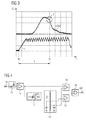
- an induction voltage UIND in the first coil L1 and in the second coil L2 ( Figure 3). This induction voltage UIND is particularly easy to detect in the respective de-energized coil.
- Figure 3 shows a diagram in which a profile of an electric current I through the first coil L1 and the second coil L2 is shown in the Bestromen.
- the energization of the respective coil begins at a reference time t0 by the switching on of the respective coil associated first switch SW1 and second switch SW2.
- the reference time t0 is representative of a beginning of a current drive cycle of the valve.
- the electric current I increases until a predetermined current is reached. Then, the current I by alternately turning on and off the first Switch SW1 held in a predetermined range.
- the induction voltage UIND is induced in the respective currentless coil.
- the induction voltage UIND shows a characteristic course in the form of a bend B.
- the kink B is caused by the end of the movement of the valve piston 2. Since the induction voltage UIND is not further induced after the time t1, it falls faster after the time t1 than before the first time t1. The end of the movement of the valve piston 2 can thus be detected by the detection of the buckling B in the course of the induction voltage UIND.
- the time t1 is representative of the end of the movement of the valve piston 2 in the valve.
- the current drive cycle is terminated by stopping the energization of the first coil L1 and the second coil L2.
- Figure 4 shows a block diagram of a device for detecting the end of the movement of the valve piston 2 in the valve.
- the device has an input IN, via which the device, the induction voltage UIND can be fed.
- a protection circuit 10 is provided on the input side of the device in order to protect the device from an excessive input voltage at the input IN and thus to prevent damage to the device.
- the protection circuit 10 is coupled to a buffer 11 on the output side of the buffer 11, the induction voltage UIND can be tapped.
- the buffer 11 is coupled to a differentiator 12, which forms a first derivative of the induction voltage UIND after the time and provides this on the output side. Further is in the apparatus, a reference generator 13 is provided which generates and specifies a predetermined induction voltage threshold and a predetermined derivative threshold.
- a first comparator 14 is provided for comparing the induction voltage UIND with the predetermined induction voltage threshold.
- a second comparator 15 is provided for comparing the first derivative of the induction voltage UIND with the predetermined derivative threshold.
- the first comparator 14 and the second comparator 15 are logically linked together via an AND gate 16.
- An output OUT of the device is formed by an output of the AND gate 16. At the output OUT, the detection of the end of the movement of the valve piston 2 is signaled when the induction voltage UIND is greater than the predetermined induction voltage threshold and the first derivative of the induction voltage UIND drops the predetermined derivative threshold.
- the signal at the output OUT e.g. an output pulse at or shortly after time t1 can be supplied, for example, to the control device 9, which is designed to control the valve in such a way that e.g. a predetermined amount of fuel is injected.
- a method corresponding to the block diagram may also be provided, e.g. in the form of a program executed by the controller 9.
- the bend B in the course of the induction voltage UIND can also be detected by a differently configured device or by another method.
- FIG. 5 shows a first flow chart of a first method for checking the valve.
- the first method starts in a step S1.
- the step S1 is preferably carried out at the beginning of the current drive cycle.
- the reference time t0 is detected.
- the step S3 is repeated until the end of the movement of the valve piston 2 has been detected or the repetition is canceled due to the exceeding of a predetermined maximum time since the start of the current drive cycle.
- a step S4 the time t1 is detected. Further, a current switching period T is determined depending on the time t1 and the reference time t0, for example, as a difference of the time t1 and the reference time t0.
- a step S5 it is checked whether a first error condition is fulfilled. The first error condition is satisfied when the switching period T is greater than a predetermined first threshold value THR1. If the first error condition is fulfilled, then in a step S6 the time t1 is stored as a first error time t_ERR1 and a first error number n1 is increased, for example by one.
- a step S7 it is checked whether the first number of errors n1 is greater than a predefined first maximum number of errors n1_max. If this condition is fulfilled, then a first error ERR1 of the valve is detected in a step S8 and the first method is ended in a step S11. If the condition is not met in step S7, then the first method is also ended in step S11.
- step S9 If the first error condition is not met in step S5, ie if the current switching time T is less than or equal to the predetermined first threshold value THR1, then it is checked in a step S9 whether a difference between the time t1 and the first error time t_ERR1 is greater than a predetermined one first maximum error interval T_ERR1.
- the predetermined first maximum error interval T_ERR1 is a time period in which the first error condition must be satisfied in step S5 for at least the predetermined first maximum number of errors n1_max in order to detect the error of the valve. Therefore, in a step S10, the first error number n1 is set to a neutral value, e.g.
- step S10 the difference of the time t1 and the first error time t_ERR1 is greater than the predetermined first maximum error interval T_ERR1.
- the first method is ended after step S10 in step S11.
- the first method is also ended in step S11 if the condition is not satisfied in step S9.
- FIG. 6 shows a second flow chart of a second method for checking the valve.
- the second process starts in a step S20 which is executed in accordance with the step S1 at the beginning of the current drive cycle.
- the reference time t0 is detected in the step S21.
- the step S22 according to the step S3, the end of the movement of the valve piston in the valve is detected.
- the time t1 and the switching time T are determined in accordance with the step S4.
- the switching period T is stored.
- a current moving average value m is determined as a function of the current switching time duration T and a predetermined number of the respectively stored switching time duration of preceding drive cycles. For example Approximately ten or twenty previous drive cycles are taken into account for determining the current moving average m.
- a step S26 it is checked whether a second error condition is fulfilled.
- the second error condition in step S26 is satisfied when an amount of a difference of the current shift time T and either the current moving average m, which includes the current shift time T, or a moving average determined for a preceding drive cycle, which is the current shift time T not greater than a predetermined second threshold THR2. If the second error condition is satisfied, then in a step S27 the time t1 is stored as a second error time t_ERR2 and a second error number n2 is increased, e.g. at one. In a step S28, it is checked whether the second error number n2 is greater than a predetermined second maximum error number n2_max. If this condition is met, then a second error ERR2 is detected in a step S29 and the second method is ended in a step S32. The second process is also terminated in step S32 if the condition is not satisfied in step S28.
- step S30 checks whether a difference of the time t1 and the second error time t_ERR2 is greater than a predetermined second maximum error interval T_ERR2. Is this condition satisfied, then in a step S31, the second error number n2 is set to a neutral value, for example to zero. The second process is ended in step S32. The second process is also terminated in step S32 if the condition is not satisfied in step S30.
- the second error ERR2 represents a fluctuation of the switching time T.
- the fluctuating switching time T can lead to corresponding fluctuations of the metered amount of fluid. In the internal combustion engine thereby pollutant emissions can be increased.
- FIG. 7 shows a third flow diagram of a third method for checking the valve.
- the third process starts in a step S40 which is executed in accordance with the step S1 or the step S20.
- step S40 is preferably performed less frequently than step S1 or step S20, e.g. only once in each hour of operation of the valve or once per operation of the valve, e.g. each at the start of operation of the valve.
- the reference time t0 is detected in accordance with the step S21.
- step S42 according to the step S22, the end of the movement of the valve spool 2 in the valve is detected.
- the time t1 and the switching time T are determined in accordance with the step S23.
- step S44 the switching period T is stored in accordance with step S24, and in step S45, the current moving average m is determined in accordance with step S25.
- a step S46 the current moving average m is stored.
- a step S47 it is checked whether a third error condition is satisfied.
- the third error condition is satisfied when a quantity representative of a current moving average rate of change is greater than a predetermined third threshold THR3.
- the size is determined depending on the current moving average m and at least one previously stored moving average.
- the mean values taken into account for determining the size are preferably random samples of the respective current moving average m, which are stored over longer periods of time, for example months or years or depending on the operating time duration of the valve.
- the third method uses the recognition that the switching time of the valve changes slowly due to wear, but accelerates the change when the failure of the valve is imminent.
- step S47 If the third error condition is satisfied in step S47, then a third error ERR3 is detected in a step S48 and the third method is ended in a step S49. The third method is also terminated in step S49 if the condition is not satisfied in step S47.
- the third method can also be extended such that the third error ERR3 is only detected if the third error condition is met within a further predetermined maximum error interval for at least one further predetermined number of errors.
- FIG. 8 shows a fourth flow chart of a fourth method for checking the valve.
- the fourth method comprises the first, second and third methods.
- the process starts in a step S60.
- a step S61 the first method is executed.
- a step S62 the second process is executed, and in a step S63, the third method performed.
- the fourth method is ended in a step S64 and, if appropriate, continued after a waiting period TW in the step S60.
- steps S2, S3 and S4 are preferably performed together for the first, second and third methods, so that the steps S21, S22 and S23 as well as the steps S41, S42 and S43 do not have to be executed again. Accordingly, steps S44 and S45 need not be executed again if steps S24 and S25 have already been executed.
- the first, second and third methods can each be carried out independently of the respective other two methods. Likewise, these methods can be performed in any combination. The order of execution can be chosen arbitrarily.
- the first, second, third or fourth methods are carried out when predetermined operating conditions of the valve prevail, e.g. at a given temperature.
- predetermined operating conditions of the valve e.g. at a given temperature.
- switching durations or moving average values determined in different drive cycles are particularly easy to compare with one another.
- the current shift time T or the current moving average m is corrected depending on currently prevailing operating conditions of the valve. This correction can for example be based on a reference temperature.
Abstract
Description
Die Erfindung betrifft ein Verfahren zum Überprüfen eines Ventils, insbesondere eines magnetisch bistabilen Solenoid-Ventils für ein Einspritzventil einer Brennkraftmaschine in einem Kraftfahrzeug.The invention relates to a method for checking a valve, in particular a magnetically bistable solenoid valve for an injection valve of an internal combustion engine in a motor vehicle.
An Brennkraftmaschinen, insbesondere in Kraftfahrzeugen, werden hohe Anforderungen gestellt. Die Schadstoffemissionen unterliegen gesetzlichen Bestimmungen und der Kunde verlangt nach einem geringen Kraftstoffverbrauch und einem sicheren und zuverlässigen Betrieb. Durch direktes Einspritzen des Kraftstoffs in die jeweilige Verbrennungskammer der Brennkraftmaschine mit hohem Druck, z.B. mit über 2000 Bar bei Dieselkraftstoff oder über 100 Bar bei Benzin, sowie gegebenenfalls durch Zuführen des Kraftstoffs in mehreren Teileinspritzungen je Einspritzvorgang kann die Gemischaufbereitung verbessert werden und so der Kraftstoffverbrauch und die Entstehung von Schadstoffemissionen verringert werden. Die Anforderungen an die Präzision und Dynamik der Einspritzventile sind daher hoch. Gefordert sind beispielsweise Ventilschaltzeiten von z.B. etwa 100 bis 500 Mikrosekunden, so dass bei dem hohen Kraftstoffdruck geringe Kraftstoffmengen, z.B. wenige Mikrogramm, präzise eingespritzt werden können. Für Diesel-Pkw-Motoren weisen die Einspritzventile dazu einen Piezoaktor zum Betätigen des Ventils auf. Jedoch sind Einspritzventile mit Piezoaktor teuer. Einspritzventile, die einen Magnetaktor aufweisen, erreichen jedoch die geforderten Ventilschaltzeiten nicht.On internal combustion engines, especially in motor vehicles, high demands are made. The pollutant emissions are subject to legal regulations and the customer demands low fuel consumption and safe and reliable operation. By directly injecting the fuel into the respective combustion chamber of the engine at high pressure, eg with over 2,000 bar for diesel fuel or over 100 bar for gasoline, and optionally by supplying the fuel in several injections per injection process, the mixture preparation can be improved and so the fuel consumption and the generation of pollutant emissions are reduced. The demands on the precision and dynamics of the injection valves are therefore high. For example, valve switching times of, for example, about 100 to 500 microseconds are required, so that at the high fuel pressure, small quantities of fuel, eg a few micrograms, can be injected precisely. For diesel passenger car engines, the injectors have a piezoelectric actuator for actuating the valve. However, injectors with piezoelectric actuator are expensive. Injectors having a solenoid actuator, however, do not reach the required valve switching times.
Für großvolumige und langsam laufende Diesel-Lkw-Motoren, beispielsweise ein Sechs-Zylinder-Motor mit neun Litern Hubraum und einer Betriebsdrehzahl von maximal 1.800 Umdrehungen pro Minute, sind die Anforderung an die Ventilschaltzeiten geringer. Um eine vorgegebene Kraftstoffmenge präzise zumessen zu können, müssen eine Zeitdauer, während der das Ventil geöffnet ist, und die Ventilschaltzeit möglichst präzise bekannt sein.For large-volume and slow-running diesel truck engines, for example, a six-cylinder engine with a displacement of nine liters and an operating speed of a maximum of 1,800 revolutions per minute, the demand for the valve switching times are lower. In order to measure a given amount of fuel precisely, a period of time during which the valve is open and the valve switching time must be known as precisely as possible.
Die Aufgabe der Erfindung ist, ein Verfahren zum Überprüfen eines Ventils zu schaffen, das einfach und zuverlässig ist.The object of the invention is to provide a method for checking a valve which is simple and reliable.
Die Aufgabe wird gelöst durch die Merkmale der unabhängigen Patentansprüche. Vorteilhafte Weiterbildungen der Erfindung sind in den Unteransprüchen gekennzeichnet.The object is solved by the features of the independent claims. Advantageous developments of the invention are characterized in the subclaims.
Die Erfindung zeichnet sich aus durch ein Verfahren zum Überprüfen eines Ventils mit einem Ventilkolben, der abhängig von einer Ansteuerung des Ventils bewegbar ist zum Öffnen und Schließen des Ventils. Das Ventil umfasst mindestens eine Spule und mindestens ein magnetisiertes Bauelement. Das Ventil ist so ausgebildet, dass eine Induktionsspannung in der mindestens einen Spule induziert wird durch ein Bewegen des Ventilkolbens in dem Ventil durch ein von dem magnetisierten Bauelement erzeugtes Magnetfeld. Ein Referenzzeitpunkt wird erfasst, der repräsentativ ist für einen Beginn eines aktuellen Ansteuerzyklus des Ventils. In dem aktuellen Ansteuerzyklus wird ein Zeitpunkt abhängig von einem charakteristischen Verlauf der Induktionsspannung ermittelt, der repräsentativ ist für ein Ende eines Bewegungsvorgangs des Ventilkolbens in dem Ventil. Eine aktuelle Schaltzeitdauer wird ermittelt abhängig von dem Zeitpunkt und dem Referenzzeitpunkt. Mindestens eine Fehlerbedingung wird ermittelt abhängig von der Schaltzeitdauer. Ein Fehler wird erkannt, wenn die mindestens eine Fehlerbedingung erfüllt ist.The invention is characterized by a method for checking a valve with a valve piston, which is movable depending on a control of the valve for opening and closing the valve. The valve comprises at least one coil and at least one magnetized component. The valve is configured such that an induction voltage is induced in the at least one coil by moving the valve piston in the valve by a magnetic field generated by the magnetized component. A reference time is detected that is representative of a beginning of a current drive cycle of the valve. In the current drive cycle, a time is determined depending on a characteristic curve of the induction voltage, which is representative of an end of a movement process of the valve piston in the valve. A current switching time is determined depending on the time and the reference time. At least one error condition is determined depending on the Switching period. An error is detected if the at least one error condition is fulfilled.
Der Vorteil ist, dass abhängig von der Schaltzeitdauer der Fehler des Ventils einfach und zuverlässig erkannt werden kann. Insbesondere ist eine mechanische Fehlfunktion des Ventils, z.B. durch hydraulisches Kleben des Ventilkolbens, zuverlässig erkennbar. Ist das Ventil beispielsweise Teil eines Einspritzventils einer Brennkraftmaschine eines Kraftfahrzeugs, dann kann der Fehler des Ventils zu einer erhöhten Schadstoffemission führen. Durch das Erkennen des Fehlers besteht die Möglichkeit, dem Fahrer des Fahrzeugs den Fehler zu signalisieren, so dass der Fehler in einer Werkstatt behoben werden kann.The advantage is that, depending on the switching time, the error of the valve can be detected easily and reliably. In particular, a mechanical malfunction of the valve, e.g. by hydraulic bonding of the valve piston, reliably recognizable. If the valve is, for example, part of an injection valve of an internal combustion engine of a motor vehicle, then the fault of the valve can lead to increased pollutant emission. By detecting the error, it is possible to signal the error to the driver of the vehicle, so that the error can be corrected in a workshop.
In einer vorteilhaften Ausgestaltung der Erfindung ist die mindestens eine Fehlerbedingung erfüllt, wenn die Schaltzeitdauer größer ist als ein vorgegebener erster Schwellenwert. Dies hat den Vorteil, dass ein Ausbleiben des Bewegungsvorgangs des Ventilkolbens oder ein verzögerter Bewegungsvorgang sehr einfach als Fehler erkannt werden kann.In an advantageous embodiment of the invention, the at least one error condition is fulfilled if the switching time duration is greater than a predetermined first threshold value. This has the advantage that a failure of the movement process of the valve piston or a delayed movement process can be easily detected as a fault.
In einer weiteren vorteilhaften Ausgestaltung der Erfindung wird ein aktueller gleitender Mittelwert ermittelt abhängig von der aktuellen Schaltzeitdauer und einer vorgegebenen Anzahl der jeweiligen Schaltzeitdauer vorangegangener Ansteuerzyklen. Die mindestens eine Fehlerbedingung ist erfüllt, wenn ein Betrag einer Differenz der aktuellen Schaltzeitdauer und des aktuellen gleitenden Mittelwerts oder eines für einen vorangegangenen Ansteuerzyklus ermittelten gleitenden Mittelwerts größer ist als ein vorgegebener zweiter Schwellenwert. Dies hat den Vorteil, dass Schwankungen der Schaltzeitdauer des Ventils einfach und zuverlässig als Fehler erkannt werden können. Dadurch kann die Wartung oder Instandsetzung des Ventils veranlasst werden, bevor das Ventil ausfällt.In a further advantageous embodiment of the invention, a current moving average is determined as a function of the current switching time duration and a predetermined number of the respective switching time duration of preceding drive cycles. The at least one error condition is met when an amount of a difference of the current shift time period and the current moving average value or a moving average value determined for a preceding drive cycle is greater than a predetermined second threshold value. This has the advantage that fluctuations in the switching time of the valve are easily and reliably detected as errors can. This will allow the valve to be serviced or repaired before the valve fails.
In einer weiteren vorteilhaften Ausgestaltung der Erfindung wird der aktuelle gleitende Mittelwert ermittelt abhängig von der aktuellen Schaltzeitdauer und der vorgegebenen Anzahl der jeweiligen Schaltzeitdauer vorangegangener Ansteuerzyklen. Der aktuelle gleitende Mittelwert wird gespeichert. Abhängig von dem aktuellen gleitenden Mittelwert und mindestens einem bereits zuvor gespeicherten gleitenden Mittelwert wird eine Größe ermittelt, die repräsentativ ist für eine aktuelle Veränderungsrate des gleitenden Mittelwerts. Die mindestens eine Fehlerbedingung ist erfüllt, wenn die Größe größer ist als ein vorgegebener dritter Schwellenwert. Dies hat den Vorteil, dass bereits bevor das Ventil ausfällt erkannt werden kann, dass sich Eigenschaften des Ventils so verändern, dass von einem Ausfall des Ventils in naher Zukunft ausgegangen werden kann. Beispielsweise verlängert sich die Schaltzeitdauer mit zunehmendem Alter des Ventils durch Verschleiß. Die Wartung oder Instandsetzung oder der Austausch des Ventils kann so frühzeitig veranlasst werden.In a further advantageous embodiment of the invention, the current moving average is determined as a function of the current switching time duration and the predetermined number of the respective switching time duration of preceding drive cycles. The current moving average is saved. Depending on the current moving average and at least one previously stored moving average, a quantity representative of a current rate of change of the moving average is determined. The at least one error condition is met when the magnitude is greater than a predetermined third threshold. This has the advantage that even before the valve fails, it can be recognized that properties of the valve change so that a failure of the valve in the near future can be assumed. For example, the switching time lengthens with wear as the valve ages. The maintenance or repair or replacement of the valve can be arranged so early.
In einer weiteren vorteilhaften Ausgestaltung der Erfindung wird der Fehler jeweils nur dann erkannt, wenn die mindestens eine Fehlerbedingung innerhalb eines vorgegebenen maximalen Fehlerintervalls für mindestens eine vorgegebene Fehleranzahl erfüllt ist. Der Vorteil ist, dass selten auftretende Ausreißer der Schaltzeitdauer nicht zu einer Fehlermeldung führen. Dadurch werden unnötige Fehlermeldungen und gegebenenfalls Wartungsarbeiten vermieden.In a further advantageous embodiment of the invention, the error is detected in each case only if the at least one error condition is fulfilled within a predetermined maximum error interval for at least one predetermined number of errors. The advantage is that rarely occurring outliers of the switching time do not lead to an error message. This avoids unnecessary error messages and possibly maintenance.
In einer weiteren vorteilhaften Ausgestaltung der Erfindung wird das Verfahren durchgeführt, wenn vorgegebene Betriebsbedingungen des Ventils vorherrschen. Dies hat den Vorteil, dass die ermittelte Schaltzeitdauer oder der gleitende Mittelwert des aktuellen Ansteuerzyklus besonders gut vergleichbar sind mit zuvor ermittelten Schaltzeitdauern beziehungsweise gleitenden Mittelwerten. Das Überprüfen des Ventils ist so besonders zuverlässig.In a further advantageous embodiment of the invention, the method is performed when predetermined operating conditions prevail of the valve. This has the advantage that the determined switching period or the moving average of the current drive cycle are particularly well comparable with previously determined switching periods or moving averages. Checking the valve is so very reliable.
In einer weiteren vorteilhaften Ausgestaltung der Erfindung werden die Schaltzeitdauer oder der gleitende Mittelwert korrigiert abhängig von aktuell vorherrschenden Betriebsbedingungen des Ventils. Dies hat den Vorteil, dass bei unterschiedlichen Betriebsbedingungen ermittelte Schaltzeitdauern und gleitende Mittelwerte gut miteinander vergleichbar werden und das Überprüfen des Ventils so besonders zuverlässig ist.In a further advantageous embodiment of the invention, the switching period or the moving average are corrected depending on currently prevailing operating conditions of the valve. This has the advantage that switching time durations and moving average values determined under different operating conditions can be compared to one another in a good manner and the checking of the valve is thus particularly reliable.
Ausführungsbeispiele der Erfindung sind im Folgenden anhand der schematischen Zeichnungen erläutert.Embodiments of the invention are explained below with reference to the schematic drawings.
Es zeigen:
- Figur 1
- ein Ventil,
Figur 2- eine Schaltungsanordnung für ein Ansteuern des Ventils,
Figur 3- ein Stromzeit- und Spannungszeitdiagramm,
Figur 4- ein Blockschaltbild einer Vorrichtung zum Erkennen eines Endes einer Bewegung eines Ventilkolbens in dem Ventil,
Figur 5- ein erstes Ablaufdiagramm,
Figur 6- ein zweites Ablaufdiagramm,
Figur 7- ein drittes Ablaufdiagramm und
Figur 8- ein viertes Ablaufdiagramm.
- FIG. 1
- a valve,
- FIG. 2
- a circuit arrangement for actuating the valve,
- FIG. 3
- a current time and voltage time diagram,
- FIG. 4
- a block diagram of an apparatus for detecting an end of a movement of a valve piston in the valve,
- FIG. 5
- a first flowchart,
- FIG. 6
- a second flowchart,
- FIG. 7
- a third flow chart and
- FIG. 8
- a fourth flowchart.
Elemente gleicher Konstruktion oder Funktion sind figuren-übergreifend mit den gleichen Bezugszeichen versehen.Elements of the same construction or function are provided across the figures with the same reference numerals.
Ein Ventil, z.B. ein Steuerventil für ein Einspritzventil für eine Brennkraftmaschine in einem Kraftfahrzeug, umfasst ein Ventilgehäuse 1, das eine Ausnehmung aufweist, in der ein Ventilkolben 2 axial beweglich angeordnet ist (Figur 1). Das Ventil weist einen Einlass 3 und zwei Auslässe 4 auf, die in dem Ventilgehäuse 1 ausgebildet sind. Ferner sind in dem Ventilgehäuse 1 Abflüsse 5 ausgebildet. Der Einlass 3 ist beispielsweise mit einem nicht dargestellten Fluidreservoir koppelbar, aus dem dem Ventil ein Fluid, z.B. Hydrauliköl oder Motoröl, zugeführt werden kann. Die Auslässe 4 münden beispielsweise in einen nicht dargestellten Steuerraum, an den z.B. ein Hydraulikstempel angrenzt, der abhängig von einem Fluiddruck in dem Steuerraum bewegbar ist zum Öffnen und Schließen des Einspritzventils.A valve, e.g. a control valve for an injection valve for an internal combustion engine in a motor vehicle, comprising a valve housing 1, which has a recess in which a
Abhängig von einer axialen Position des Ventilkolbens 2 in der Ausnehmung des Ventilgehäuses 1 ist entweder der Einlass 3 hydraulisch über Nuten 8, die in dem Ventilkolben 2 und dem Ventilgehäuse 1 ausgebildet sind, mit den Auslässen 4 gekoppelt oder sind die Auslässe 4 mit den Abflüssen 5 gekoppelt. Durch die Abflüsse 5 kann das Fluid aus dem Steuerraum abfließen.Depending on an axial position of the
Das Ventil weist eine erste Kappe 6 und eine zweite Kappe 7 auf, die jeweils an einem axialen Ende des Ventils angeordnet sind. Die erste Kappe 6 und die zweite Kappe 7 begrenzen den Hub des Ventilkolbens 2 in dem Ventilgehäuse 1. Angrenzend an die erste Kappe 6 ist eine erste Spule L1 und angrenzend an die zweite Kappe 7 ist eine zweite Spule L2 angeordnet. Durch ein geeignetes Bestromen der ersten Spule L1 bzw. der zweiten Spule L2 kann ein Magnetfeld so aufgebaut werden, dass der Ventilkolben 2 durch dieses angezogen wird und gegen die durch die erste Kappe 6 bzw. die zweite Kappe 7 gebildete Hubbegrenzung bewegt wird. Vorzugsweise sind die erste Kappe 6 und die zweite Kappe 7 so ausgebildet, dass auch nach dem Beenden des Bestromens der ersten Spule L1 bzw. der zweiten Spule L2 durch ein entsprechendes Magnetisieren der ersten Kappe 6 bzw. der zweiten Kappe 7 ein Remanenzmagnetfeld erhalten bleibt. Der Ventilkolben 2 kann so seine aktuelle Position an der ersten Kappe 6 bzw. der zweiten Kappe 7 beibehalten, bis der Ventilkolben 2 durch das Bestromen der jeweils gegenüberliegenden Spule zu der dieser zugeordneten Kappe gezogen wird. Das Ventil bildet somit ein magnetisch bistabiles Solenoid-Ventil. Das Ventil kann jedoch auch anders ausgebildet sein.The valve has a
Figur 2 zeigt eine Schaltungsanordnung, die ausgebildet ist zum Ansteuern des Ventils. Die Schaltungsanordnung weist eine Steuereinrichtung 9 auf, die beispielsweise ein pulsweitenmoduliertes Steuersignal erzeugt, das einem ersten Schalter SW1 zugeführt wird. Der erste Schalter SW1 ist elektrisch zwischen einem positiven Potenzial einer Batteriespannung UBAT und einem ersten Anschluss der ersten Spule L1 angeordnet. Die Batteriespannung UBAT beträgt beispielsweise etwa 24 Volt. Ferner ist der erste Schalter SW1 und der erste Anschluss der ersten Spule L1 über eine in Sperrrichtung angeordnete erste Diode D1 mit einem negativen Potenzial der Batteriespannung UBAT gekoppelt, das als ein Massepotenzial GND bezeichnet ist.Figure 2 shows a circuit arrangement which is designed for driving the valve. The circuit arrangement has a
Ein zweiter Anschluss der ersten Spule L1 ist über einen zweiten Schalter SW2 mit dem Massepotenzial GND gekoppelt. Der zweite Schalter SW2 ist vorgesehen für ein Auswählen des Ventils, wenn weitere Ventile durch die Steuereinrichtung 9 angesteuert werden. Ferner ist der zweite Anschluss der ersten Spule L1 über eine in Sperrrichtung geschaltete zweite Diode D2 mit dem positiven Potenzial der Batteriespannung UBAT gekoppelt. Der erste Schalter SW1, der zweite Schalter SW2, die erste Diode D1 und die zweite Diode D2 sind entsprechend für die zweite Spule L2 vorgesehen. Die Steuereinrichtung 9 ist vorzugsweise ausgebildet, das pulsweitenmodulierte Steuersignal entsprechend auch für die zweite Spule L2 zu erzeugen.A second terminal of the first coil L1 is coupled to the ground potential GND via a second switch SW2. The second switch SW2 is provided for selecting the valve when further valves are controlled by the
Die erste Spule L1 und die zweite Spule L2 werden vorzugsweise so abwechselnd bestromt, dass der Ventilkolben 2 in die jeweils andere axiale Position an der ersten Kappe 6 bzw. der zweiten Kappe 7 bewegt wird. Vorzugsweise wird die jeweils unbestromte Spule genutzt, um die Bewegung des Ventilkolbens 2 in dem Ventilgehäuse 1 zu erfassen. Dadurch, dass die erste Kappe 6 und die zweite Kappe 7 oder auch das Ventilgehäuse 1 oder der Ventilkolben 2 magnetisiert sind, kann durch das Bewegen des Ventilkolbens 2 durch das vorherrschende Magnetfeld eine Induktionsspannung UIND in der ersten Spule L1 und in der zweiten Spule L2 induziert werden (Figur 3). Diese Induktionsspannung UIND ist in der jeweils unbestromten Spule besonders einfach erfassbar.The first coil L1 and the second coil L2 are preferably energized alternately so that the
Figur 3 zeigt ein Diagramm, in dem ein Verlauf eines elektrischen Stroms I durch die erste Spule L1 bzw. die zweite Spule L2 bei dem Bestromen dargestellt ist. Das Bestromen der jeweiligen Spule beginnt zu einem Referenzzeitpunkt t0 durch das Einschalten des der jeweiligen Spule zugeordneten ersten Schalters SW1 und zweiten Schalters SW2. Der Referenzzeitpunkt t0 ist repräsentativ für einen Beginn eines aktuellen Ansteuerzyklus des Ventils. Der elektrische Strom I steigt an, bis ein vorgegebener Strom erreicht ist. Dann wird der Strom I durch abwechselndes Ein- und Ausschalten des ersten Schalters SW1 in einem vorgegebenen Bereich gehalten. Mit einem Beginn der Bewegung des Ventilkolbens 2 durch das vorherrschende Magnetfeld wird in der jeweils unbestromten Spule die Induktionsspannung UIND induziert. Schlägt der Ventilkolben 2 zu einem Zeitpunkt t1 gegen die durch die erste Kappe 6 bzw. die zweite Kappe 7 gebildete Hubbegrenzung, dann zeigt die Induktionsspannung UIND einen charakteristischen Verlauf in Form eines Knicks B. Der Knick B wird verursacht durch das Ende der Bewegung des Ventilkolbens 2. Da die Induktionsspannung UIND nach dem Zeitpunkt t1 nicht weiter induziert wird, fällt diese nach dem Zeitpunkt t1 schneller als vor dem ersten Zeitpunkt t1. Das Ende der Bewegung des Ventilkolbens 2 kann somit durch das Erkennen des Knicks B in dem Verlauf der Induktionsspannung UIND erkannt werden. Der Zeitpunkt t1 ist repräsentativ für das Ende des Bewegungsvorgangs des Ventilkolbens 2 in dem Ventil. Der aktuelle Ansteuerzyklus wird beendet durch Beenden des Bestromens der ersten Spule L1 bzw. der zweiten Spule L2.Figure 3 shows a diagram in which a profile of an electric current I through the first coil L1 and the second coil L2 is shown in the Bestromen. The energization of the respective coil begins at a reference time t0 by the switching on of the respective coil associated first switch SW1 and second switch SW2. The reference time t0 is representative of a beginning of a current drive cycle of the valve. The electric current I increases until a predetermined current is reached. Then, the current I by alternately turning on and off the first Switch SW1 held in a predetermined range. With a beginning of the movement of the
Figur 4 zeigt ein Blockschaltbild einer Vorrichtung zum Erkennen des Endes der Bewegung des Ventilkolbens 2 in dem Ventil. Die Vorrichtung weist einen Eingang IN auf, über den der Vorrichtung die Induktionsspannung UIND zuführbar ist. Eine Schutzschaltung 10 ist eingangsseitig der Vorrichtung vorgesehen, um die Vorrichtung vor einer zu großen Eingangsspannung an dem Eingang IN zu schützen und so ein Beschädigen der Vorrichtung zu verhindern. Die Schutzschaltung 10 ist gekoppelt mit einem Puffer 11. Ausgangsseitig des Puffers 11 kann die Induktionsspannung UIND abgegriffen werden.Figure 4 shows a block diagram of a device for detecting the end of the movement of the
Der Puffer 11 ist mit einem Differenzierer 12 gekoppelt, der eine erste Ableitung der Induktionsspannung UIND nach der Zeit bildet und diese ausgangsseitig bereitstellt. Ferner ist in der Vorrichtung ein Referenzerzeuger 13 vorgesehen, der einen vorgegebenen Induktionsspannungsschwellenwert und einen vorgegebenen Ableitungsschwellenwert erzeugt und vorgibt.The
Ein erster Vergleicher 14 ist vorgesehen zum Vergleichen der Induktionsspannung UIND mit dem vorgegebenen Induktionsspannungsschwellenwert. Ein zweiter Vergleicher 15 ist vorgesehen zum Vergleichen der ersten Ableitung der Induktionsspannung UIND mit dem vorgegebenen Ableitungsschwellenwert. Ausgangsseitig sind der erste Vergleicher 14 und der zweite Vergleicher 15 über ein Und-Glied 16 logisch miteinander verknüpft. Ein Ausgang OUT der Vorrichtung ist gebildet durch einen Ausgang des Und-Glieds 16. An dem Ausgang OUT wird das Erkennen des Endes der Bewegung des Ventilkolbens 2 signalisiert, wenn die Induktionsspannung UIND größer ist als der vorgegebene Induktionsspannungsschwellenwert und die erste Ableitung der Induktionsspannung UIND unter den vorgegebenen Ableitungsschwellenwert fällt.A
Das Signal an dem Ausgang OUT, z.B. ein Ausgangspuls zu oder kurz nach dem Zeitpunkt t1, kann beispielsweise der Steuereinrichtung 9 zugeführt werden, die ausgebildet ist, das Ventil so anzusteuern, dass z.B. eine vorgegebene Kraftstoffmenge eingespritzt wird. Es kann jedoch ebenso ein dem Blockschaltbild entsprechendes Verfahren vorgesehen sein, z.B. in Form eines Programms, das durch die Steuereinrichtung 9 ausgeführt wird. Der Knick B in dem Verlauf der Induktionsspannung UIND kann jedoch auch durch eine anders ausgebildete Vorrichtung oder durch ein anderes Verfahren erkannt werden.The signal at the output OUT, e.g. an output pulse at or shortly after time t1 can be supplied, for example, to the
Figur 5 zeigt ein erstes Ablaufdiagramm eines ersten Verfahrens zum Überprüfen des Ventils. Das erste Verfahren beginnt in einem Schritt S1. Der Schritt S1 wird vorzugsweise ausgeführt zu Beginn des aktuellen Ansteuerzyklus. In einem Schritt S2 wird der Referenzzeitpunkt t0 erfasst. In einem Schritt S3 wird überprüft, ob der Knick B in dem Verlauf der Induktionsspannung UIND aufgetreten ist. Beispielsweise wird in dem Schritt S3 überprüft, ob an dem Ausgang OUT der in Figur 4 dargestellten Vorrichtung der Ausgangspuls, d.h. das Signal für das Erkennen des Endes der Bewegung des Ventilkolbens 2 in dem Ventil, aufgetreten ist. Der Schritt S3 wird solange wiederholt, bis das Ende der Bewegung des Ventilkolbens 2 erkannt wurde oder das Wiederholen abgebrochen wird aufgrund des Überschreitens einer vorgegebenen maximalen Zeitdauer seit dem Beginn des aktuellen Ansteuerzyklus.FIG. 5 shows a first flow chart of a first method for checking the valve. The first method starts in a step S1. The step S1 is preferably carried out at the beginning of the current drive cycle. In a step S2, the reference time t0 is detected. In a step S3, it is checked whether the bend B has occurred in the course of the induction voltage UIND. For example, it is checked in step S3 whether the output pulse, ie the signal for detecting the end of the movement of the
In einem Schritt S4 wird der Zeitpunkt t1 erfasst. Ferner wird eine aktuelle Schaltzeitdauer T abhängig von dem Zeitpunkt t1 und dem Referenzzeitpunkt t0 ermittelt, z.B. als eine Differenz des Zeitpunkts t1 und des Referenzzeitpunkts t0. In einem Schritt S5 wird überprüft, ob eine erste Fehlerbedingung erfüllt ist. Die erste Fehlerbedingung ist erfüllt, wenn die Schaltzeitdauer T größer ist als ein vorgegebener erster Schwellenwert THR1. Ist die erste Fehlerbedingung erfüllt, dann wird in einem Schritt S6 der Zeitpunkt t1 als ein erster Fehlerzeitpunkt t_ERR1 gespeichert und eine erste Fehleranzahl n1 erhöht, z.B. um Eins. In einem Schritt S7 wird überprüft, ob die erste Fehleranzahl n1 größer ist als eine vorgegebene erste maximale Fehleranzahl n1_max. Ist diese Bedingung erfüllt, dann wird in einem Schritt S8 ein erster Fehler ERR1 des Ventils erkannt und das erste Verfahren in einem Schritt S11 beendet. Ist die Bedingung in dem Schritt S7 nicht erfüllt, dann wird das erste Verfahren ebenfalls in dem Schritt S11 beendet.In a step S4, the time t1 is detected. Further, a current switching period T is determined depending on the time t1 and the reference time t0, for example, as a difference of the time t1 and the reference time t0. In a step S5 it is checked whether a first error condition is fulfilled. The first error condition is satisfied when the switching period T is greater than a predetermined first threshold value THR1. If the first error condition is fulfilled, then in a step S6 the time t1 is stored as a first error time t_ERR1 and a first error number n1 is increased, for example by one. In a step S7, it is checked whether the first number of errors n1 is greater than a predefined first maximum number of errors n1_max. If this condition is fulfilled, then a first error ERR1 of the valve is detected in a step S8 and the first method is ended in a step S11. If the condition is not met in step S7, then the first method is also ended in step S11.
Ist die erste Fehlerbedingung in dem Schritt S5 nicht erfüllt, ist also die aktuelle Schaltzeitdauer T kleiner oder gleich dem vorgegebenen ersten Schwellenwert THR1, dann wird in einem Schritt S9 überprüft, ob eine Differenz des Zeitpunkts t1 und des ersten Fehlerzeitpunkts t_ERR1 größer ist als ein vorgegebenes erstes maximales Fehlerintervall T_ERR1. Das vorgegebene erste maximale Fehlerintervall T_ERR1 ist eine Zeitdauer, in der die erste Fehlerbedingung in dem Schritt S5 für mindestens die vorgegebene erste maximale Fehleranzahl n1_max erfüllt sein muss, um den Fehler des Ventils zu erkennen. Deshalb wird in einem Schritt S10 die erste Fehleranzahl n1 auf einen neutralen Wert gesetzt, z.B. auf Null, wenn die Differenz des Zeitpunkts t1 und des ersten Fehlerzeitpunkts t_ERR1 größer ist als das vorgegebene erste maximale Fehlerintervall T_ERR1. Das erste Verfahren wird nach dem Schritt S10 in dem Schritt S11 beendet. Das erste Verfahren wird ebenfalls in dem Schritt S11 beendet, wenn die Bedingung in dem Schritt S9 nicht erfüllt ist.If the first error condition is not met in step S5, ie if the current switching time T is less than or equal to the predetermined first threshold value THR1, then it is checked in a step S9 whether a difference between the time t1 and the first error time t_ERR1 is greater than a predetermined one first maximum error interval T_ERR1. The predetermined first maximum error interval T_ERR1 is a time period in which the first error condition must be satisfied in step S5 for at least the predetermined first maximum number of errors n1_max in order to detect the error of the valve. Therefore, in a step S10, the first error number n1 is set to a neutral value, e.g. to zero, when the difference of the time t1 and the first error time t_ERR1 is greater than the predetermined first maximum error interval T_ERR1. The first method is ended after step S10 in step S11. The first method is also ended in step S11 if the condition is not satisfied in step S9.
Figur 6 zeigt ein zweites Ablaufdiagramm eines zweiten Verfahrens zum Überprüfen des Ventils. Das zweite Verfahren beginnt in einem Schritt S20, das entsprechend dem Schritt S1 zu Beginn des aktuellen Ansteuerzyklus ausgeführt wird. Entsprechend dem Schritt S2 wird in dem Schritt S21 der Referenzzeitpunkt t0 erfasst. In einem Schritt S22 wird entsprechend dem Schritt S3 das Ende der Bewegung des Ventilkolbens in dem Ventil erkannt. In einem Schritt S23 wird entsprechend dem Schritt S4 der Zeitpunkt t1 und die Schaltzeitdauer T ermittelt. In einem Schritt S24 wird die Schaltzeitdauer T gespeichert. In einem Schritt S25 wird ein aktueller gleitender Mittelwert m ermittelt abhängig von der aktuellen Schaltzeitdauer T und einer vorgegebenen Anzahl der jeweils gespeicherten Schaltzeitdauer vorangegangener Ansteuerzyklen. Beispielsweise werden etwa zehn oder zwanzig vorangegangene Ansteuerzyklen für das Ermitteln des aktuellen gleitenden Mittelwerts m berücksichtigt.FIG. 6 shows a second flow chart of a second method for checking the valve. The second process starts in a step S20 which is executed in accordance with the step S1 at the beginning of the current drive cycle. According to the step S2, the reference time t0 is detected in the step S21. In a step S22, according to the step S3, the end of the movement of the valve piston in the valve is detected. In a step S23, the time t1 and the switching time T are determined in accordance with the step S4. In a step S24, the switching period T is stored. In a step S25, a current moving average value m is determined as a function of the current switching time duration T and a predetermined number of the respectively stored switching time duration of preceding drive cycles. For example Approximately ten or twenty previous drive cycles are taken into account for determining the current moving average m.
In einem Schritt S26 wird überprüft, ob eine zweite Fehlerbedingung erfüllt ist. Die zweite Fehlerbedingung in dem Schritt S26 ist erfüllt, wenn ein Betrag einer Differenz der aktuellen Schaltzeitdauer T und entweder des aktuellen gleitenden Mittelwerts m, der also die aktuelle Schaltzeitdauer T umfasst, oder eines für einen vorangegangenen Ansteuerzyklus ermittelten gleitenden Mittelwerts, der die aktuelle Schaltzeitdauer T nicht umfasst, größer ist als ein vorgegebener zweiter Schwellenwert THR2. Ist die zweite Fehlerbedingung erfüllt, dann wird in einem Schritt S27 der Zeitpunkt t1 als ein zweiter Fehlerzeitpunkt t_ERR2 gespeichert und eine zweite Fehleranzahl n2 erhöht, z.B. um Eins. In einem Schritt S28 wird überprüft, ob die zweite Fehleranzahl n2 größer ist als eine vorgegebene zweite maximale Fehleranzahl n2_max. Ist diese Bedingung erfüllt, dann wird in einem Schritt S29 ein zweiter Fehler ERR2 erkannt und das zweite Verfahren in einem Schritt S32 beendet. Das zweite Verfahren wird ebenfalls in dem Schritt S32 beendet, wenn die Bedingung in dem Schritt S28 nicht erfüllt ist.In a step S26 it is checked whether a second error condition is fulfilled. The second error condition in step S26 is satisfied when an amount of a difference of the current shift time T and either the current moving average m, which includes the current shift time T, or a moving average determined for a preceding drive cycle, which is the current shift time T not greater than a predetermined second threshold THR2. If the second error condition is satisfied, then in a step S27 the time t1 is stored as a second error time t_ERR2 and a second error number n2 is increased, e.g. at one. In a step S28, it is checked whether the second error number n2 is greater than a predetermined second maximum error number n2_max. If this condition is met, then a second error ERR2 is detected in a step S29 and the second method is ended in a step S32. The second process is also terminated in step S32 if the condition is not satisfied in step S28.
Ist die zweite Fehlerbedingung in dem Schritt S26 nicht erfüllt, d.h. der Betrag der Differenz der aktuellen Schaltzeitdauer T und entweder des aktuellen gleitenden Mittelwerts m oder des für den vorangegangenen Ansteuerzyklus ermittelten gleitenden Mittelwerts ist kleiner oder gleich als der vorgegebene zweite Schwellenwert THR2, dann wird in einem Schritt S30 überprüft, ob eine Differenz des Zeitpunkts t1 und des zweiten Fehlerzeitpunkts t_ERR2 größer ist als ein vorgegebenes zweites maximales Fehlerintervall T_ERR2. Ist diese Bedingung erfüllt, dann wird in einem Schritt S31 die zweite Fehleranzahl n2 auf einen neutralen Wert gesetzt, z.B. auf Null. Das zweite Verfahren wird in dem Schritt S32 beendet. Das zweite Verfahren wird ebenfalls in dem Schritt S32 beendet, wenn die Bedingung in dem Schritt S30 nicht erfüllt ist.If the second error condition is not satisfied in step S26, ie, the amount of the difference of the current shift time T and either the current moving average m or the moving average determined for the preceding drive cycle is less than or equal to the predetermined second threshold THR2, then a step S30 checks whether a difference of the time t1 and the second error time t_ERR2 is greater than a predetermined second maximum error interval T_ERR2. Is this condition satisfied, then in a step S31, the second error number n2 is set to a neutral value, for example to zero. The second process is ended in step S32. The second process is also terminated in step S32 if the condition is not satisfied in step S30.
Der zweite Fehler ERR2 repräsentiert ein Schwanken der Schaltzeitdauer T. Die schwankende Schaltzeitdauer T kann zu entsprechenden Schwankungen der zugemessenen Fluidmenge führen. Bei der Brennkraftmaschine können dadurch Schadstoffemissionen erhöht werden.The second error ERR2 represents a fluctuation of the switching time T. The fluctuating switching time T can lead to corresponding fluctuations of the metered amount of fluid. In the internal combustion engine thereby pollutant emissions can be increased.
Figur 7 zeigt ein drittes Ablaufdiagramm eines dritten Verfahrens zum Überprüfen des Ventils. Das dritte Verfahren beginnt in einem Schritt S40 der entsprechend dem Schritt S1 oder dem Schritt S20 ausgeführt wird. Der Schritt S40 wird jedoch vorzugsweise seltener ausgeführt als der Schritt S1 oder der Schritt S20, z.B. nur ein Mal in jeder Betriebsstunde des Ventils oder ein Mal je Betrieb des Ventils, z.B. jeweils bei Betriebsbeginn des Ventils. In einem Schritt S41 wird entsprechend dem Schritt S21 der Referenzzeitpunkt t0 erfasst. In einem Schritt S42 wird entsprechend dem Schritt S22 das Ende der Bewegung des Ventilkolbens 2 in dem Ventil erfasst. In einem Schritt S43 wird entsprechend dem Schritt S23 der Zeitpunkt t1 und die Schaltzeitdauer T ermittelt. In einem Schritt S44 wird entsprechend dem Schritt S24 die Schaltzeitdauer T gespeichert und in einem Schritt S45 wird entsprechend dem Schritt S25 der aktuelle gleitende Mittelwert m ermittelt.FIG. 7 shows a third flow diagram of a third method for checking the valve. The third process starts in a step S40 which is executed in accordance with the step S1 or the step S20. However, step S40 is preferably performed less frequently than step S1 or step S20, e.g. only once in each hour of operation of the valve or once per operation of the valve, e.g. each at the start of operation of the valve. In a step S41, the reference time t0 is detected in accordance with the step S21. In a step S42, according to the step S22, the end of the movement of the
In einem Schritt S46 wird der aktuelle gleitende Mittelwert m gespeichert. In einem Schritt S47 wird überprüft, ob eine dritte Fehlerbedingung erfüllt ist. Die dritte Fehlerbedingung ist erfüllt, wenn eine Größe, die repräsentativ ist für eine aktuelle Veränderungsrate des gleitenden Mittelwerts, größer ist als ein vorgegebener dritter Schwellenwert THR3. Die Größe wird ermittelt abhängig von dem aktuellen gleitenden Mittelwert m und mindestens einem bereits zuvor gespeicherten gleitenden Mittelwert. Die für das Ermitteln der Größe berücksichtigten Mittelwerte sind vorzugsweise Stichproben des jeweils aktuellen gleitenden Mittelwerts m, die über größere Zeiträume, z.B. Monate oder Jahre oder abhängig von der Betriebszeitdauer des Ventils gespeichert werden. Das dritte Verfahren nutzt die Erkenntnis, dass die Schaltzeitdauer des Ventils sich bedingt durch Verschleiß langsam verändert, sich die Veränderung jedoch beschleunigt, wenn der Ausfall des Ventils kurz bevorsteht. Ist die dritte Fehlerbedingung in dem Schritt S47 erfüllt, dann wird in einem Schritt S48 ein dritter Fehler ERR3 erkannt und das dritte Verfahren in einem Schritt S49 beendet. Das dritte Verfahren wird ebenfalls in dem Schritt S49 beendet, wenn die Bedingung in dem Schritt S47 nicht erfüllt ist.In a step S46, the current moving average m is stored. In a step S47, it is checked whether a third error condition is satisfied. The third error condition is satisfied when a quantity representative of a current moving average rate of change is greater than a predetermined third threshold THR3. The size is determined depending on the current moving average m and at least one previously stored moving average. The mean values taken into account for determining the size are preferably random samples of the respective current moving average m, which are stored over longer periods of time, for example months or years or depending on the operating time duration of the valve. The third method uses the recognition that the switching time of the valve changes slowly due to wear, but accelerates the change when the failure of the valve is imminent. If the third error condition is satisfied in step S47, then a third error ERR3 is detected in a step S48 and the third method is ended in a step S49. The third method is also terminated in step S49 if the condition is not satisfied in step S47.
Entsprechend dem ersten Verfahren und dem zweiten Verfahren kann auch das dritte Verfahren so erweitert werden, dass der dritte Fehler ERR3 nur dann erkannt wird, wenn die dritte Fehlerbedingung innerhalb eines weiteren vorgegebenen maximalen Fehlerintervalls für mindestens eine weitere vorgegebene Fehleranzahl erfüllt ist.According to the first method and the second method, the third method can also be extended such that the third error ERR3 is only detected if the third error condition is met within a further predetermined maximum error interval for at least one further predetermined number of errors.
Figur 8 zeigt ein viertes Ablaufdiagramm eines vierten Verfahrens zum Überprüfen des Ventils. Das vierte Verfahren umfasst das erste, zweite und dritte Verfahren. Das Verfahren beginnt in einem Schritt S60. In einem Schritt S61 wird das erste Verfahren ausgeführt. In einem Schritt S62 wird das zweite Verfahren ausgeführt und in einem Schritt S63 wird das dritte Verfahren ausgeführt. Das vierte Verfahren wird in einem Schritt S64 beendet und gegebenenfalls nach einer Wartezeitdauer TW in dem Schritt S60 fortgeführt.FIG. 8 shows a fourth flow chart of a fourth method for checking the valve. The fourth method comprises the first, second and third methods. The process starts in a step S60. In a step S61, the first method is executed. In a step S62, the second process is executed, and in a step S63, the third method performed. The fourth method is ended in a step S64 and, if appropriate, continued after a waiting period TW in the step S60.
Die Schritte S2, S3 und S4 werden vorzugsweise für das erste, zweite und dritte Verfahren gemeinsam ausgeführt, so dass die Schritte S21, S22 und S23 sowie die Schritte S41, S42 und S43 nicht erneut ausgeführt werden müssen. Entsprechend müssen die Schritte S44 und S45 nicht erneut ausgeführt werden, wenn bereits die Schritte S24 und S25 ausgeführt wurden.The steps S2, S3 and S4 are preferably performed together for the first, second and third methods, so that the steps S21, S22 and S23 as well as the steps S41, S42 and S43 do not have to be executed again. Accordingly, steps S44 and S45 need not be executed again if steps S24 and S25 have already been executed.
Das erste, zweite und dritte Verfahren ist jeweils unabhängig von den jeweils anderen beiden Verfahren ausführbar. Ebenso können diese Verfahren in beliebiger Kombinationen ausgeführt werden. Dabei kann die Reihenfolge der Ausführung beliebig gewählt werden.The first, second and third methods can each be carried out independently of the respective other two methods. Likewise, these methods can be performed in any combination. The order of execution can be chosen arbitrarily.
Bevorzugt werden das erste, das zweite, das dritte oder das vierte Verfahren ausgeführt, wenn vorgegebene Betriebsbedingungen des Ventils vorherrschen, z.B. bei einer vorgegebenen Temperatur. Dadurch sind in verschiedenen Ansteuerzyklen ermittelte Schaltzeitdauern oder gleitende Mittelwerte besonders gut miteinander vergleichbar. Alternativ wird die aktuelle Schaltzeitdauer T oder der aktuelle gleitende Mittelwert m korrigiert abhängig von aktuell vorherrschenden Betriebsbedingungen des Ventils. Diese Korrektur kann beispielsweise bezogen auf eine Referenztemperatur erfolgen.Preferably, the first, second, third or fourth methods are carried out when predetermined operating conditions of the valve prevail, e.g. at a given temperature. As a result, switching durations or moving average values determined in different drive cycles are particularly easy to compare with one another. Alternatively, the current shift time T or the current moving average m is corrected depending on currently prevailing operating conditions of the valve. This correction can for example be based on a reference temperature.
Claims (7)
Applications Claiming Priority (1)
| Application Number | Priority Date | Filing Date | Title |
|---|---|---|---|
| DE102005050338A DE102005050338A1 (en) | 2005-10-20 | 2005-10-20 | Method for checking a valve |
Publications (2)
| Publication Number | Publication Date |
|---|---|
| EP1777400A2 true EP1777400A2 (en) | 2007-04-25 |
| EP1777400A3 EP1777400A3 (en) | 2010-03-31 |
Family
ID=37682619
Family Applications (1)
| Application Number | Title | Priority Date | Filing Date |
|---|---|---|---|
| EP06120658A Withdrawn EP1777400A3 (en) | 2005-10-20 | 2006-09-14 | Method for testing a valve |
Country Status (3)
| Country | Link |
|---|---|
| US (1) | US8019569B2 (en) |
| EP (1) | EP1777400A3 (en) |
| DE (1) | DE102005050338A1 (en) |
Cited By (5)
| Publication number | Priority date | Publication date | Assignee | Title |
|---|---|---|---|---|
| WO2011003704A1 (en) * | 2009-07-10 | 2011-01-13 | Continental Automotive Gmbh | Determining the closing time of a fuel injection valve based on evaluating the actuation voltage |
| EP2281113A2 (en) * | 2008-05-17 | 2011-02-09 | Daimler AG | Valve operating mechanism |
| WO2011134794A1 (en) * | 2010-04-26 | 2011-11-03 | Continental Automotive Gmbh | Electric actuation of a valve based on knowledge of the closing time of the valve |
| DE102012200275A1 (en) | 2012-01-11 | 2013-07-11 | Continental Automotive Gmbh | Method for determining movement behavior of fuel injector of combustion engine of motor car, involves determining physical activity of injection process so as to determine movement behavior of injector in primary operating state |
| US20220196184A1 (en) * | 2020-12-21 | 2022-06-23 | Buerkert Werke Gmbh & Co. Kg | Method of diagnosing a valve, diagnosis module, and valve |
Families Citing this family (8)
| Publication number | Priority date | Publication date | Assignee | Title |
|---|---|---|---|---|
| DE102005044886B4 (en) * | 2005-09-20 | 2009-12-24 | Continental Automotive Gmbh | Apparatus and method for detecting an end of movement of a valve piston in a valve |
| CN101978152B (en) * | 2008-03-17 | 2013-07-03 | 胡斯华纳有限公司 | Fuel supply unit |
| RU2456469C2 (en) * | 2008-03-17 | 2012-07-20 | Хускварна Аб | Fuel feed station |
| EP2728230A1 (en) * | 2012-10-30 | 2014-05-07 | Danfoss A/S | Valve actuator device, in particular for a heating or cooling system valve |
| DE102013017446A1 (en) * | 2013-10-22 | 2015-04-23 | Man Diesel & Turbo Se | Engine control unit |
| CN103629176B (en) * | 2013-11-11 | 2015-11-11 | 湖南中联重科智能技术有限公司 | Movement component coordination action control, Apparatus and system |
| CN104775961A (en) * | 2015-03-31 | 2015-07-15 | 苏州固基电子科技有限公司 | Fault detection circuit for line fault of solenoid valve |
| US10968731B2 (en) * | 2016-11-21 | 2021-04-06 | Schlumberger Technology Corporation | System and method for monitoring a blowout preventer |
Citations (9)
| Publication number | Priority date | Publication date | Assignee | Title |
|---|---|---|---|---|
| DE3730523A1 (en) * | 1987-09-11 | 1989-03-30 | Bosch Gmbh Robert | METHOD AND DEVICE FOR DETECTING THE SWITCHING TIMES OF SOLENOID VALVES |
| DE3817770A1 (en) * | 1988-05-26 | 1989-11-30 | Daimler Benz Ag | Device for the timed operation of an electromagnetic valve |
| DE3942836A1 (en) * | 1989-12-23 | 1991-06-27 | Daimler Benz Ag | METHOD FOR DETECTING THE MOTION AND POSITION OF A COMPONENT OF A INDUCTIVE ELECTRICAL CONSUMER THROUGH MAGNETIC INTERACTION BETWEEN TWO END POSITIONS |
| DE4308811A1 (en) * | 1992-07-21 | 1994-01-27 | Bosch Gmbh Robert | Diesel engine EM actuated fuel metering valve controller - has current sensor feeding back information to controller to determine on and off switching points of valve |
| EP1128049A2 (en) * | 2000-02-23 | 2001-08-29 | Mazda Motor Corporation | Fuel pressure control device for high pressure fuel injection system |
| EP1162360A2 (en) * | 2000-06-08 | 2001-12-12 | Toyota Jidosha Kabushiki Kaisha | Malfunction determining apparatus of engine system |
| US20030106365A1 (en) * | 2001-10-12 | 2003-06-12 | Honda Giken Kogyo Kabushiki Kaisha | Engine malfunction detection system |
| US20030229440A1 (en) * | 2002-05-14 | 2003-12-11 | Yasuhiro Tanaka | Control apparatus for vehicle |
| US20050030691A1 (en) * | 2003-07-21 | 2005-02-10 | Siemens Vdo Automotive Corporation | Power supply and control method for injector driver module |
Family Cites Families (16)
| Publication number | Priority date | Publication date | Assignee | Title |
|---|---|---|---|---|
| US4394742A (en) * | 1980-10-31 | 1983-07-19 | Fmc Corporation | Engine generated waveform analyzer |
| DE3244940A1 (en) * | 1982-12-04 | 1984-06-07 | Robert Bosch Gmbh, 7000 Stuttgart | METHOD AND CIRCUIT ARRANGEMENT FOR EVALUATING OUTPUT SIGNALS OF A MEASURING VALVE RECEIVED ON AN INTERNAL COMBUSTION ENGINE |
| US5535621A (en) * | 1994-03-02 | 1996-07-16 | Ford Motor Company | On-board detection of fuel injector malfunction |
| US5720261A (en) * | 1994-12-01 | 1998-02-24 | Oded E. Sturman | Valve controller systems and methods and fuel injection systems utilizing the same |
| DE19726225B4 (en) * | 1997-06-20 | 2008-02-07 | Robert Bosch Gmbh | Arrangement with one or more hydraulic actuators |
| JP3527857B2 (en) * | 1998-12-25 | 2004-05-17 | 株式会社日立製作所 | Fuel injection device and internal combustion engine |
| DE10024685A1 (en) * | 2000-05-18 | 2001-11-22 | Zeiss Carl Jena Gmbh | Auto-focusing microscope transmits image and focal position information along separate optical paths within main beam path of objective |
| DE10112639A1 (en) | 2001-03-16 | 2002-09-19 | Zeiss Carl Jena Gmbh | Auto-focussing microscope has a simple shutter arrangement that can be focussed on the imaging device together with the observation object to provide accurate microscope focussing |
| DE10127284A1 (en) | 2001-06-05 | 2002-12-12 | Zeiss Carl Jena Gmbh | Automatic focussing of a microscope using an analysis unit that compares measured values with stored design values and adjusts the microscope accordingly |
| JP4067384B2 (en) * | 2002-10-30 | 2008-03-26 | 株式会社ミクニ | Fuel injection method |
| US6754604B2 (en) * | 2002-11-01 | 2004-06-22 | Snap-On Incorporated | Method and apparatus for diagnosing fuel injectors |
| JP2004183550A (en) * | 2002-12-03 | 2004-07-02 | Isuzu Motors Ltd | Filter treating device for common-rail pressure detection value and common-rail type fuel injection controller |
| WO2004088190A1 (en) * | 2003-04-01 | 2004-10-14 | Monatec Pty Ltd | Valve monitoring method and arrangement |
| DE10319182B4 (en) | 2003-04-29 | 2008-06-12 | Carl Zeiss Jena Gmbh | Method and arrangement for determining the focus position when imaging a sample |
| JP2005249697A (en) * | 2004-03-08 | 2005-09-15 | Jeol Ltd | Nozzle plugging detecting method and analyzer |
| BRPI0403883B1 (en) * | 2004-09-10 | 2015-09-29 | Docol Metais Sanitários Ltda | SOLENOID VALVE AND SOLENOID ASSEMBLY |
-
2005
- 2005-10-20 DE DE102005050338A patent/DE102005050338A1/en not_active Withdrawn
-
2006
- 2006-09-14 EP EP06120658A patent/EP1777400A3/en not_active Withdrawn
- 2006-10-20 US US11/584,269 patent/US8019569B2/en not_active Expired - Fee Related
Patent Citations (9)
| Publication number | Priority date | Publication date | Assignee | Title |
|---|---|---|---|---|
| DE3730523A1 (en) * | 1987-09-11 | 1989-03-30 | Bosch Gmbh Robert | METHOD AND DEVICE FOR DETECTING THE SWITCHING TIMES OF SOLENOID VALVES |
| DE3817770A1 (en) * | 1988-05-26 | 1989-11-30 | Daimler Benz Ag | Device for the timed operation of an electromagnetic valve |
| DE3942836A1 (en) * | 1989-12-23 | 1991-06-27 | Daimler Benz Ag | METHOD FOR DETECTING THE MOTION AND POSITION OF A COMPONENT OF A INDUCTIVE ELECTRICAL CONSUMER THROUGH MAGNETIC INTERACTION BETWEEN TWO END POSITIONS |
| DE4308811A1 (en) * | 1992-07-21 | 1994-01-27 | Bosch Gmbh Robert | Diesel engine EM actuated fuel metering valve controller - has current sensor feeding back information to controller to determine on and off switching points of valve |
| EP1128049A2 (en) * | 2000-02-23 | 2001-08-29 | Mazda Motor Corporation | Fuel pressure control device for high pressure fuel injection system |
| EP1162360A2 (en) * | 2000-06-08 | 2001-12-12 | Toyota Jidosha Kabushiki Kaisha | Malfunction determining apparatus of engine system |
| US20030106365A1 (en) * | 2001-10-12 | 2003-06-12 | Honda Giken Kogyo Kabushiki Kaisha | Engine malfunction detection system |
| US20030229440A1 (en) * | 2002-05-14 | 2003-12-11 | Yasuhiro Tanaka | Control apparatus for vehicle |
| US20050030691A1 (en) * | 2003-07-21 | 2005-02-10 | Siemens Vdo Automotive Corporation | Power supply and control method for injector driver module |
Cited By (8)
| Publication number | Priority date | Publication date | Assignee | Title |
|---|---|---|---|---|
| EP2281113A2 (en) * | 2008-05-17 | 2011-02-09 | Daimler AG | Valve operating mechanism |
| WO2011003704A1 (en) * | 2009-07-10 | 2011-01-13 | Continental Automotive Gmbh | Determining the closing time of a fuel injection valve based on evaluating the actuation voltage |
| US8935114B2 (en) | 2009-07-10 | 2015-01-13 | Continental Automotive Gmbh | Determining the closing time of a fuel injection valve based on evaluating the actuation voltage |
| WO2011134794A1 (en) * | 2010-04-26 | 2011-11-03 | Continental Automotive Gmbh | Electric actuation of a valve based on knowledge of the closing time of the valve |
| US8887560B2 (en) | 2010-04-26 | 2014-11-18 | Continental Automotive Gmbh | Electric actuation of a valve based on knowledge of the closing time of the valve |
| DE102012200275A1 (en) | 2012-01-11 | 2013-07-11 | Continental Automotive Gmbh | Method for determining movement behavior of fuel injector of combustion engine of motor car, involves determining physical activity of injection process so as to determine movement behavior of injector in primary operating state |
| DE102012200275B4 (en) * | 2012-01-11 | 2016-10-20 | Continental Automotive Gmbh | Determining a movement behavior of a fuel injector based on the movement behavior in a multi-injection modified operating state |
| US20220196184A1 (en) * | 2020-12-21 | 2022-06-23 | Buerkert Werke Gmbh & Co. Kg | Method of diagnosing a valve, diagnosis module, and valve |
Also Published As
| Publication number | Publication date |
|---|---|
| US20070090315A1 (en) | 2007-04-26 |
| EP1777400A3 (en) | 2010-03-31 |
| DE102005050338A1 (en) | 2007-05-03 |
| US8019569B2 (en) | 2011-09-13 |
Similar Documents
| Publication | Publication Date | Title |
|---|---|---|
| EP1777400A2 (en) | Method for testing a valve | |
| DE102005044886B4 (en) | Apparatus and method for detecting an end of movement of a valve piston in a valve | |
| EP2386021B1 (en) | Method for operation of a fuel injection system | |
| EP1979598B1 (en) | Device for switching inductive fuel injection valves | |
| EP1381764B1 (en) | Method and device for controlling a piezo-actuator | |
| WO2011036035A1 (en) | Method and device for determining a fuel pressure present at a direct injection valve | |
| DE102009050467A1 (en) | Method for controlling and regulating an internal combustion engine | |
| DE102011004613A1 (en) | Method for monitoring the state of a piezo injector of a fuel injection system | |
| DE102013222603A1 (en) | Method for detecting an error in the opening behavior of an injector | |
| EP1423594B1 (en) | Method and device for controlling piezo-driven fuel injection valves | |
| DE102014220795A1 (en) | Method for setting a current in a solenoid valve | |
| WO2013068173A1 (en) | Method and device for operating an internal combustion engine | |
| DE102010043306B4 (en) | Method for operating a magnetic switching element, electrical circuit for operating the magnetic switching element and a control and/or regulating device | |
| DE102006027823B4 (en) | Method and device for adjusting the valve characteristic of a fuel injection valve | |
| DE102009050469A1 (en) | Method for controlling and regulating an internal combustion engine | |
| EP2635784A1 (en) | Method for operating a switching element | |
| DE102007000064A1 (en) | Fuel injection device e.g. for controlling fuel injection in fuel injecting device, has fuel injected by valve to each cylinder and control device has collection mechanism for recording malfunction which is caused by valve | |
| DE102013211469A1 (en) | Method for operating at least one injection valve | |
| EP2861855A1 (en) | Method for operating a valve | |
| DE102006033932B4 (en) | Method for operating an internal combustion engine | |
| EP2726723B1 (en) | Fuel injection valve | |
| DE10140550B4 (en) | Method for monitoring the function of fast-switching injection valves | |
| DE102011086151A1 (en) | Method for operating solenoid valve, particularly fuel injection valve of combustion engine, involves driving coil and moving armature between resting seat and stroke stop | |
| DE102017215536A1 (en) | Method for checking a solenoid valve of a fuel injector | |
| DE102015217776A1 (en) | A method of detecting damage to a nozzle needle of a fuel injector or the nozzle needle seat |
Legal Events
| Date | Code | Title | Description |
|---|---|---|---|
| PUAI | Public reference made under article 153(3) epc to a published international application that has entered the european phase |
Free format text: ORIGINAL CODE: 0009012 |
|
| AK | Designated contracting states |
Kind code of ref document: A2 Designated state(s): AT BE BG CH CY CZ DE DK EE ES FI FR GB GR HU IE IS IT LI LT LU LV MC NL PL PT RO SE SI SK TR |
|
| AX | Request for extension of the european patent |
Extension state: AL BA HR MK YU |
|
| RAP1 | Party data changed (applicant data changed or rights of an application transferred) |
Owner name: CONTINENTAL AUTOMOTIVE GMBH |
|
| PUAL | Search report despatched |
Free format text: ORIGINAL CODE: 0009013 |
|
| AK | Designated contracting states |
Kind code of ref document: A3 Designated state(s): AT BE BG CH CY CZ DE DK EE ES FI FR GB GR HU IE IS IT LI LT LU LV MC NL PL PT RO SE SI SK TR |
|
| AX | Request for extension of the european patent |
Extension state: AL BA HR MK RS |
|
| 17P | Request for examination filed |
Effective date: 20100930 |
|
| AKX | Designation fees paid |
Designated state(s): DE FR |
|
| 17Q | First examination report despatched |
Effective date: 20101206 |
|
| STAA | Information on the status of an ep patent application or granted ep patent |
Free format text: STATUS: THE APPLICATION IS DEEMED TO BE WITHDRAWN |
|
| 18D | Application deemed to be withdrawn |
Effective date: 20181025 |