EP1775618A2 - Mikroskop mit Mitteln zum Zusammenfügen von Bildern, die mit unterschiedlichen Auflösungen und unterschiedlichen Mikroskopieverfahren aufgenommen wurden - Google Patents
Mikroskop mit Mitteln zum Zusammenfügen von Bildern, die mit unterschiedlichen Auflösungen und unterschiedlichen Mikroskopieverfahren aufgenommen wurden Download PDFInfo
- Publication number
- EP1775618A2 EP1775618A2 EP06021331A EP06021331A EP1775618A2 EP 1775618 A2 EP1775618 A2 EP 1775618A2 EP 06021331 A EP06021331 A EP 06021331A EP 06021331 A EP06021331 A EP 06021331A EP 1775618 A2 EP1775618 A2 EP 1775618A2
- Authority
- EP
- European Patent Office
- Prior art keywords
- image
- unit
- capture
- specimen
- display
- Prior art date
- Legal status (The legal status is an assumption and is not a legal conclusion. Google has not performed a legal analysis and makes no representation as to the accuracy of the status listed.)
- Ceased
Links
Images


Classifications
-
- G—PHYSICS
- G02—OPTICS
- G02B—OPTICAL ELEMENTS, SYSTEMS OR APPARATUS
- G02B21/00—Microscopes
- G02B21/36—Microscopes arranged for photographic purposes or projection purposes or digital imaging or video purposes including associated control and data processing arrangements
- G02B21/365—Control or image processing arrangements for digital or video microscopes
- G02B21/367—Control or image processing arrangements for digital or video microscopes providing an output produced by processing a plurality of individual source images, e.g. image tiling, montage, composite images, depth sectioning, image comparison
-
- G—PHYSICS
- G02—OPTICS
- G02B—OPTICAL ELEMENTS, SYSTEMS OR APPARATUS
- G02B21/00—Microscopes
- G02B21/36—Microscopes arranged for photographic purposes or projection purposes or digital imaging or video purposes including associated control and data processing arrangements
- G02B21/368—Microscopes arranged for photographic purposes or projection purposes or digital imaging or video purposes including associated control and data processing arrangements details of associated display arrangements, e.g. mounting of LCD monitor
Definitions
- the present invention relates to microscope technology, and more specifically to technology of acquiring a microscopic image of a specimen and displaying an acquired microscopic image.
- observation range a range that can be simultaneously observed (observation range) mainly depends on the magnification of an objective lens.
- observation range is limited to only a part of the specimen.
- a request is made to grasp the entire image of a specimen to avoid missing a point to be diagnosed. Additionally, with the development of information processing technology, more images are expressed as electronic information in the pathological diagnosis, and there is also a request to obtain high resolution of old solver salt film for an image observed by a microscope through a video camera, etc.
- Japanese Published Patent Application No. H9-281405 Japanese Published Patent Application No. H10-333056 , or National Publication of International patent Application No. 2002-514319 discloses a system for reconstituting an image of a specimen by dividing an image of a specimen into small sections in advance, capturing a part of the specimen corresponding to the small section using a high-resolution objective lens, and combining the microscopic images for the obtained small sections.
- a system which is called a virtual microscope system
- a specimen can be observed by a microscope even in an environment where there is practically not a specimen, and using the image processing technology, the following observation can be performed as in actually observing a specimen.
- a wide-angle image can be provided by displaying a combined scale-down microscopic image while high resolution can be provided during observation with high magnification by displaying a partial image captured for each small section.
- the display range of a microscopic image being displayed is moved corresponding to the X-Y direction operation (the moving operation in the horizontal direction on the plane perpendicular to the optical axis) by an observer.
- a specimen can be diagnosed by without time restrictions, and different points of the same specimen can be observed although there are a plurality of users who perform a diagnosis in different places by sharing image data indicating a microscopic image among each user.
- the image data can be backed up. Therefore, the above-mentioned system enables a specimen to be observed anywhere at any time in the same status.
- the virtual microscope system is efficient and highly accurate in observing an entity of a specimen using a microscope, thereby ensuring high reliability.
- the microscope apparatus includes a capture unit for capturing a microscopic image of a specimen in a predetermined microscopy, a capture control unit for controlling the capture unit and capturing a microscopic image about the same specimen with a plurality of predetermined resolutions, and a microscopy switch unit for switching the microscopy.
- the capture control unit includes a first capture control unit for allowing the capture unit to capture the specimen with a first resolution controlled in advance, a definition unit for defining a plurality of small sections obtained by dividing a first microscopic image captured by the capture unit under control of the first capture control unit, a second capture control unit for allowing the capture unit to capture a portion corresponding to the small section of the specimen with a predetermined second resolution as a resolution higher than the first resolution, an image combination unit for generating a second microscopic image with the second resolution for the specimen by combining the microscopic images for the respective small sections captured by the capture unit under control of the second capture control unit, and an image accumulation unit for accumulating the combined microscopic images captured in plural microscopies for each specimen.
- the microscope system includes a switch unit for switching an observation method, a microscope apparatus for observing a specimen in an observation method switched by the switch unit, a stage for moving the specimen, a division unit for dividing the specimen into a plurality of sections, a capture coordinate acquisition unit for acquiring a Z capture coordinate as a coordinate in an optical axis direction when the specimen is captured, a capture coordinate record unit for recording the Z capture coordinate, a capture unit for capturing the specimen in the sections based on the Z capture coordinate, an image record unit for recording an image of the specimen captured by the capture unit, and an image combination unit for combining images recorded in the image record unit, an image display unit for displaying the images combined by the image combination unit.
- the capture unit captures the specimen in a second observation method switched by the switch unit based on the Z capture coordinate acquired by the capture coordinate acquisition unit in a first observation method switched by the switch unit.
- the microscope system includes a stage on which a specimen is placed, a division unit for dividing the specimen into a plurality of small sections, a capture condition setting unit for setting a capture condition used when the specimen is captured, a capture unit for capturing the specimen of the small sections based on the capture condition set by the capture condition setting unit and acquiring an image in the small section, a capture parameter acquisition unit for acquiring a capture parameter when the specimen is captured by the capture unit in the small sections based on the capture condition set by the capture condition setting unit, and an image composition unit for combining the images in the adjacent small sections acquired by the capture unit, and an image display unit for displaying an image.
- FIG. 1 shows the first example of the microscope system for embodying the present invention.
- a microscope apparatus 1 comprises as a transmission observation optical system a transmission illumination light source 6, a collector lens 7 for collecting illumination light of the transmission illumination light source 6, a transmission filter unit 8, a transmission field iris 9, a transmission aperture iris 10, a capacitor optical element unit 11, and a top lens unit 12.
- a transmission observation optical system it comprises an incident-light illumination light source 13, a collector lens 14, an incident-light filter unit 15, an incident-light shutter 16, an incident-light field iris 17, and an incident-light aperture iris 18.
- an electric stage 20 capable of moving up, down, left, and right on which a specimen 19 is placed on the observation optical path where the optical path of the transmission observation optical system overlaps the optical path of the incident-light observation optical system.
- the movement of the electric stage 20 is controlled by a stage X-Y drive control unit 21 and a stage Z drive control unit 22.
- the electric stage 20 has the function of detecting an origin point (not shown in the attached drawings) using an origin point sensor, and can set coordinates for each unit of the specimen 19 placed on the electric stage 20.
- a revolver 24 for selecting via a revolving operation from a plurality of objective lenses 23a, 23b, ... (hereinafter generally referred to as an "objective lens 23" as necessary) a lens to be used in an observation, a cube unit 25 for switching the microscopy, and a beam splitter 27 for splitting the observation optical path toward an eyepiece 26 and a video camera 3.
- a polarizer 28 for differentiation interference observation, a DIC (differential interference contrast) prism 29, and an analyzer 30 can be inserted into the observation optical path.
- Each unit is motor driven, and the operation is controlled by a microscope controller 31 described later.
- the microscope controller 31 connected to a host system 2 has the function of controlling the entire operation of the microscope apparatus 1, changes the microscopy, adjusts the transmission illumination light source 6 and the incident-light illumination light source 13 according to a control signal from the host system 2, and has the function of transmitting the current microscopy status of the current microscope apparatus 1 to the host system 2.
- the microscope controller 31 is also connected to the stage X-Y drive control unit 21 and the stage Z drive control unit 22, and the control of the electric stage 20 can also be performed by the host system 2.
- a microscopic image of the specimen 19 captured by a video camera 3 is fetched to the host system 2 through a video board 32.
- the host system 2 can perform ON/OFF control of automatic gain, the setting of gain, ON/OFF control of automatic exposure, and the setting of exposure time on the video camera 3 through a camera controller 33.
- the host system 2 can store a microscopic image transmitted from the video camera 3 as an image data file in a data record unit 4.
- the image data recorded in the data record unit 4 is read by the host system 2, and a microscopic image expressed by the image data can be displayed on a monitor 5.
- the host system 2 also provides a so-called video AF function, which is a focusing operation that is based on the contrast of an image captured by the video camera 3.
- the host system 2 is a computer with a standard configuration having a CPU (central processing unit) for controlling the entire operation of the microscope system by executing a control program, a main memory for use by the CPU as work memory as necessary, an input unit for acquiring various instructions from a user via instruments such as a mouse, a keyboard, etc., an interface unit for managing the communication of data with each component of the microscope system, and an auxiliary storage device such as a hard disk device, etc. for storing various programs and a variety of data.
- a CPU central processing unit
- main memory for use by the CPU as work memory as necessary
- an input unit for acquiring various instructions from a user via instruments such as a mouse, a keyboard, etc.
- an interface unit for managing the communication of data with each component of the microscope system
- an auxiliary storage device such as a hard disk device, etc. for storing various programs and a variety of data.
- FIGS. 2A and 2B are explained. They are flowcharts of the microscopic image data acquisition process performed by the host system 2. The process is performed to acquire microscopic image data of the specimen 19 by the microscope system shown in FIG. 1, and is realized and started by the CPU of the host system 2 executing a predetermined control program.
- step S102 the process of determining whether or not there are any microscopies in which a microscopic image has not been captured in the microscopies acquired in the process in S101 is performed. If it is determined that there are any (if the determination result is YES), control is passed to step S103. If it is determined that all of the microscopic images have been completely captured in all acquired microscopies (if the determination result is NO), the microscopic image data acquisition process is terminated.
- an instruction is issued to the microscope controller 31, and the setting of the microscope apparatus 1 is changed to the setting of capturing a microscopic image in a microscopy in which no image has been captured.
- the microscope controller 31 controls the operation of each component of the microscope apparatus 1 to enter the state in which an image is captured in the microscopy.
- the coordinate system of the specimen 19 is set by the origin point sensor of the electric stage 20 and its initializing operation.
- S104 an instruction is issued to the microscope controller 31, and the revolver 24 is rotated to select the low-magnification objective lens 23a.
- S105 a control process for focusing operation that is based on the contrast of a microscopic image of the specimen 19 captured by the video camera 3 is performed.
- the process is performed of determining whether or not the process has been performed at a low resolution of defining a small section (mesh) corresponding to a view (angle of view) area when the specimen 19 performs a capturing process using the high-magnification objective lens 23b, captured using the low-magnification objective lens 23a. If it is determined that the defining process has been performed (if the determination result is YES), control is passed to step S111 (FIG. 2B).
- step S109 If it is determined in the determining process in S108 that the defining process has not been performed (when the determination result is NO), control is passed to step S109, and the process of defining the mesh is performed on the fetched low-resolution microscopic image. In this process, it is assumed that a 1 ⁇ n (1 row by n columns) rectangular mesh is defined.
- S110 it is determined whether or not the image of the portion of the specimen 19 is included in each partial area of the low-resolution microscopic image divided into the defined meshes, and the process of determining a mesh for which an image is captured using the high-magnification objective lens 23 is performed.
- the determination can be performed on the basis of, for example, the presence/absence of a contour image (contrast image) of the specimen 19 obtained by calculating the difference between adjacent pixels, the color of the image of each mesh, etc.
- the determined mesh for which a high-resolution microscopic image is to be captured is assigned a number.
- Control is passed to the process in FIG. 2B, an instruction is issued to the microscope controller 31 in S111, the revolver 24 is rotated, and the high-magnification objective lens 23b is selected.
- Performed in S112 is the process of determining whether or not there is a mesh on which a high-resolution capturing process in the current microscopy has not been performed in the meshes for which it is determined in the process in S110 that the high-resolution capturing process is to be performed. If it is determined that there is (if the determination result is YES), control is passed to S113. If it is determined that the high-resolution capturing process has been completed in the present microscopy on all meshes to be captured (if the determination result is NO), control is passed to the process in S117.
- S114 the controlling process for a focusing operation based on the contrast of the microscopic image of the specimen 19 captured by the video camera 3 is performed.
- an instruction is issued to the camera controller 33, and the process of capturing an image of the portion of the specimen 19 by the video camera 3 is performed.
- S116 a high-resolution microscopic image of the portion of the specimen 19 obtained by the capturing process is fetched from the video camera 3 to the host system 2 through the video board 32, and then control is returned to S112 and the above-mentioned processes are repeated.
- the low-resolution microscopic image of the specimen 19 fetched to the host system 2 in the process in S107 (FIG. 2A) and the high-resolution microscopic image of the specimen 19 obtained in the process in S117 are combined as one image data file.
- Each microscopic image to be integrated into one image data file is captured in the same microscopy.
- the above-mentioned processes constitute the microscopic image data acquisition process.
- a low-resolution microscopic image of the specimen 19 is obtained by bright-field observation, and then in processes in S108 through 110, a mesh in which a high-resolution microscopic image is to be captured for the low-resolution microscopic image using bright-field observation is determined.
- a high-resolution microscopic image is obtained for each mesh of the specimen 19 using bright-field observation, each mesh is combined in the process in S117, and a high-resolution microscopic image of the specimen 19 is generated using bright-field observation.
- the process in S118 the low-resolution microscopic image and the high-resolution microscopic image of the specimen 19 using bright-field observation are combined, and an image data file is generated.
- a low-resolution microscopic image of the specimen 19 is obtained in differentiation interference observation.
- the result of the determining process in S108 is NO
- a high-resolution microscopic image is obtained for each mesh of the specimen 19 in differentiation interference observation on the basis of the definition of the mesh for a low-resolution microscopic image using bright-field observation.
- meshes are combined and a high-resolution microscopic image of the specimen 19 is generated in differentiation interference observation.
- the process in S118 the low-resolution microscopic image and the high-resolution microscopic image of the specimen 19 in differentiation interference observation are combined and one image data file is generated.
- a low-resolution microscopic image of the specimen 19 is obtained using fluorescent observation.
- the result of the determining process in S108 is NO
- a high-resolution microscopic image for each mesh of the specimen 19 is obtained using fluorescent observation on the basis of the definition of the mesh for the low-resolution microscopic image in bright-field observation.
- meshes are combined, and a high-resolution microscopic image of the specimen 19 using fluorescent observation is generated.
- the process in S118 the low-resolution microscopic image and the high-resolution microscopic image of the specimen 19 using fluorescent observation are combined, and an image data file is generated
- FIGS. 3, 4, and 5 show examples of a high-resolution microscopic image integrated into an image data file for each microscopy as described above. These figures are explained below.
- An example of an image of layer 1 shown in FIG. 3 shows a high-resolution microscopic image of the specimen 19 captured using bright-field observation.
- An example of an image of layer 2 shown in FIG. 4 shows a high-resolution microscopic image of the specimen 19 captured in differentiation interference observation.
- An example of an image of layer 3 shown in FIG. 5 shows a high-resolution microscopic image of the specimen 19 captured using fluorescent observation.
- FIG. 6 shows the relationship among the examples of images of the respective layers.
- microscopic images are acquired in different microscopies such as bright-field observation, differentiation interference observation, fluorescent observation, etc. as shown in FIG. 6.
- the specimen 19 expressed by these microscopic images is positioned at the same coordinates in each image.
- FIGS. 7A and 7B. are described below. These figures are flowcharts of the processes of the microscopic image reproduction and display process performed by the host system 2. This process is performed to reproduce and display an image on the monitor 5 so that the microscopic image is expressed by the image data file recorded in the data record unit 4 by performing the above-mentioned microscopic image data acquisition process in the virtual observation. It is realized and started by the execution of a predetermined control program by the CPU of the host system 2.
- the images of the resolution corresponding to the objective lens 23 relating to the selection details in the process in S153 are acquired and the acquired images are temporarily stored in a predetermined work storage area of the host system 2.
- the images in the range corresponding to the magnification of the objective lens 23 relating to the selection details acquired in the process in S153 are displayed by arranging the macro images on the monitor 5 as the images obtained by enlarging the images of the macro image portion. The user performs a virtual observation while watching the microscopic images displayed on the monitor 5.
- S156 it is determined whether or not an instruction to switch the microscopy in the virtual observation of the specimen 19 has been acquired. If it is determined that the switching instruction has been acquired (when the determination result is YES), control is passed to S157. If it is determined that the switching instruction has not been acquired (if the determination result is NO), control is passed to S161.
- the files are read in which the microscopic images captured in the microscopy after the switch that relate to the instruction acquired in the process in S156 and the images having the lowest resolution in the microscopic image integrated into the read image data file are switched and displayed on the monitor 5 as new macro images.
- Control is passed to the process shown in FIG. 7B.
- S160 the microscopic images that are in the range corresponding to the magnification of the objective lens 23 currently selected in the virtual observation in the microscopic image acquired in the process in S159 and that are in the same position as the display position acquired in the process in S157 are arranged in the macro image on the monitor 5 and are then switched and displayed. Afterwards, control is returned to S156 (FIG. 7A) and the above-mentioned processes are repeated.
- the display of images on the monitor 5 is switched, and the partial images are displayed of the microscopic images captured in the microscopy relating to the switching instruction; these partial images have the same resolution as the displayed partial images before the switch of the portion of the specimen 19 at the same position as the displayed partial image before the switch.
- the microscopic images temporarily stored in a predetermined work storage area of the host system 2 are referred to, the display position being displayed as an enlarged image on the monitor 5 in the microscopic image is moved in a certain direction and by a certain amount depending on the detected move operation, switching is performed and the display is shown on the monitor 5, and then control is returned to the process in S156 and the above-mentioned processes are thereby repeated.
- the image display can be more smoothly switched than in the case where image data files are sequentially read from the data record unit 4.
- the partial images in the vicinity are displayed in accordance with the performance by the user of the operation to move the X-Y position, the image data file can be newly read from the data record unit 4, and the partial images near the newly displayed partial images can be stored in the work storage area.
- the images of the resolution corresponding to the objective lens 23 relating to the selection details determined to have been acquired in the process in S163 in the microscopic image integrated into the image data file read in the process in S152 or S158 are acquired and temporarily stored in a predetermined work storage area of the host system 2.
- the above-mentioned processes constitute the microscopic image reproduction and display process.
- the state of displaying the microscopic images in the microscopic image reproduction and display process is explained below by referring to an example in which the image data file into which the microscopic images captured in each microscopy of bright-field observation, differentiation interference observation, and the fluorescent observation is recorded in the data record unit 4.
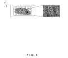
- a macro image of the specimen 19 as exemplified on the left of FIG. 8 and an enlarged image as if it were obtained by enlarging a part of the macro image as exemplified on the right of FIG. 8 are displayed on the monitor 5 in the processes in S151 to S155.
- the display of the enlarged image on the monitor 5 is switched from the display of the specimen 19 in FIG. 8 to the display of the portion moved in the X direction as exemplified in FIG. 9 in the processes in S161 and S162.
- the display of the enlarged image on the monitor 5 is switched from the display of the specimen 19 shown in FIG. 9 to the display of an enlarged image as exemplified in FIG. 10 in the processes in S163 to S165.
- the display of the image on the monitor 5 is switched from the image captured in bright-field observation to the microscopic image captured in differentiation interference observation as shown in FIG. 11A in the processes in S156 to S160.
- the enlarged images of the same resolution (display magnification) and of the portion at the same position of the specimen 19 are displayed.
- the display of the image on the monitor 5 is switched from the image captured in differentiation interference observation to the microscopic image captured on the fluorescent observation as shown in FIG. 11B in the processes in S156 to S160. Then, in the microscopic images before and after the switch of the display, the enlarged images of the same resolution (display magnification) and of the portion at the same position of the specimen 19 are displayed.
- the microscopic image of the same magnification and at the same position of the specimen 19 is immediately displayed when the microscopy is switched. Therefore, a virtual observation with high reliability in faithfully reproducing the position information of a specimen can be realized via an operation similar to that in the case in which the specimen is observed using a microscope.
- the microscopy can be switched by using a method similar to that used in the case in which the specimen is observed using a microscope in a so-called virtual microscope system that is used for reconstituting an image of a specimen by combining the microscopic images obtained by capturing a specimen.
- the three microscopies i.e. bright-field observation, differentiation interference observation, and the fluorescent observation, are exemplified, and switching between them occurs in the switching operation.
- this embodiment is not limited to the switching of these three types of microscopies, but some other microscopies can also be switched.
- the alignment in the coordinates among the microscopies is realized by the twenty origin point sensors and their initializing operations according to the present embodiment. It can also be realized by, for example, the detection of a marking made on the plate for a specimen.
- a matching method or other methods via well-known image recognition methods can also be used.
- the high-resolution microscopic images in another microscopy are captured.
- a high-resolution microscopic image can be completely captured in a specified microscopy on one mesh, and the entire high-resolution microscopic image can be obtained by repeatedly performing the capturing process on each mesh.
- FIG. 12 shows the second example of the configuration of the microscope system embodying the present invention.
- the same components as those in the first example shown in FIG. 1 are assigned the same reference numerals, and the detailed explanation is omitted here.
- the configuration shown in FIG. 12 is different from the configuration shown in FIG. 1 in that an image composition unit 34 is inserted between the host system 2 and the monitor 5.
- the image composition unit 34 At an instruction from the host system 2, the image composition unit 34 superposes and combines two images relating to the instruction, and displays the resultant image on the monitor 5.
- the operation of acquiring a microscopic image is similar to the operation according to embodiment 1, and a microscopic image is acquired by the host system 2 performing the microscopic image data acquisition process shown in FIGS. 2A and 2B.
- the host system 2 acquires the specification in the process in S101 shown in FIG. 2A.
- a low-resolution microscopic image of the specimen 19 is obtained using B-pumped observation.
- a 1 ⁇ n mesh is defined for the low-resolution microscopic image obtained using B-pumped observation, and a mesh for which a microscopic image is to be captured at a high resolution is determined.
- a high-resolution microscopic image for each mesh of the specimen 19 using B-pumped observation is obtained, each mesh is combined in the process in S117, and the high-resolution microscopic image of the specimen 19 using B-pumped observation exemplified as shown in FIG. 13 is generated.
- the low-resolution microscopic images of the specimen 19 using B-pumped observation are integrated, and one image data file is generated.
- the low-resolution microscopic image of the specimen 19 using G-pumped observation is obtained.
- the result of the determining process in S108 is NO.
- a high-resolution microscopic image is obtained for each mesh of the specimen 19 using G-pumped observation on the basis of the definition of the mesh for the low-resolution microscopic image obtained using B-pumped observation.
- each mesh is combined and a high-resolution microscopic image of the specimen 19 obtained using G-pumped observation as exemplified in FIG. 14 is generated.
- the process in S118 the low-resolution microscopic image and the high-resolution microscopic image of the specimen 19 obtained using G-pumped observation are combined, and an image data file is generated.
- microscopic images are obtained using different microscopies--such as B-pumped observation (layer 1) and G-pumped observation (layer 2)--for the same specimen 19, as shown in FIG. 15.
- layers 1 and 2 such as B-pumped observation (layer 1) and G-pumped observation (layer 2)--for the same specimen 19, as shown in FIG. 15.
- the specimens 19 indicated by these microscopic images are located at the same coordinates in each image.
- the reproducing and displaying operation is basically the same as the operation according to embodiment 1, and can be realized by the host system 2 performing the microscopic image reproduction and display process shown in FIGS. 7A and 7B. In the present embodiment, a change is made to the flowcharts shown in FIGS. 7A and 7B.
- FIG. 16 shows a changed portion in embodiment 2 of the microscopic image reproduction and display process shown in FIGS. 7A and 7B.
- the flowchart shown in FIG. 16 is performed when the result of the determining process in S163 shown in FIG. 7A is NO.
- S163 shown in FIG. 7A if it is determined that an instruction to switch the selection details of the objective lens 23 in the virtual observation of the specimen 19 has not been acquired, control is passed to the process in FIG. 16, and it is determined in S201 whether or not an instruction has been acquired to superpose and combine the microscopic image captured in another microscopy on the microscopic image being displayed.
- control is passed to S202. If it is determined that the instruction has not been acquired (NO as a determination result), then control is returned to S156 shown in FIG. 7A, and the above-mentioned processes are repeated.
- an instruction is issued to the image composition unit 34, and the partial images that are in the range corresponding to the magnification of the objective lens 23 currently selected in the virtual observation of the microscopic image acquired in the process in S204 and that are in the same position as the display position acquired in the process in S202 are superposed and combined with the microscopic image (enlarged image) currently being displayed on the monitor 5, and then control is returned to S156 shown in FIG. 7A and the above-mentioned processes are repeated.
- the process in S205 is performed by the image composition unit 34 together with the superposing, combining, and displaying operations.
- the microscope system shown in FIG. 12 can superpose, combine, and display the microscopic images from different microscopies on the same specimen 19.
- the state of superposing, combining, and displaying a microscopic image in the microscopic image reproduction and display process is explained below by referring to the case in which an image data file into which microscopic images captured in the microscopies of B-pumped observation and G-pumped observation is recorded on the data record unit 4.
- the macro image of the specimen 19 as exemplified on the left of FIG. 17 and an enlarged image that looks as if it were obtained by enlarging a portion of the macro image as exemplified on the right of FIG. 17 are displayed on the monitor 5 in the processes in S151 to S155.
- the display of an image on the monitor 5 is switched from an image captured using B-pumped observation to the microscopic image captured using G-pumped observation as exemplified in FIG. 18 in the processes in S156 to S159 shown in FIG. 7A and the processes in S160 shown in FIG. 7B.
- an enlarged image having the same resolution (display magnification) and indicating the portion at the same position as the specimen 19 is displayed.
- the display of the image on the monitor 5 is switched to the microscopic image obtained by superposing and combining the image captured using G-pumped observation and the image captured using B-pumped observation as exemplified in FIG. 19 in the processes in S201 to S205 shown in FIG. 16.
- the microscopic images before and after the display is switched are the composite enlarged images having the same resolution (display magnification) and that are at the same position as the specimen 19.
- the microscopic images that have the same magnification at the same position as the specimen 19 but that are captured with different microscopies are combined and displayed. Therefore, a virtual observation with a high reliability for faithfully reproducing the position information of a specimen can be realized via an operation similar to that in the case where the specimen is practically observed using a microscope.
- the microscopic images having the same magnification at the same position as the specimen 19 but that are captured in different microscopies are combined and displayed. It is also possible to arrange and display on the monitor 5 microscopic images that have the same magnification at the same position as the specimen 19 but that are captured in different microscopies in accordance with the purpose of the virtual observation.
- the origin point sensor of the electric stage 20 and the initializing operation are used, but it is also possible to acquire the shift of an optical axis using fluorescent cube (cube unit 25) in both B-pumped observation and G-pumped observation in advance, and thereby correct the shift from an acquired image.
- fluorescent cube cube unit 25
- a high-resolution microscopic image in one microscopy (for example, B-pumped observation) is captured on all meshes, and then a high-resolution microscopic image is captured in another microscopy (for example, G-pumped observation).
- a high-resolution microscopic image in each specified microscopy can be captured on each mesh, and in this situation the capturing operation is performed repeatedly on each mesh, thereby obtaining a high-resolution microscopic image.
- microscopies B-pumped observation and G-pumped observation
- switching between them can occur and both can be used. It is also possible to switch between various other microscopies, not limiting the present invention to only the switching between two types.
- FIG. 20 shows the third embodiment of the configuration of the microscope system for embodying the present invention.
- the same components as those in the second example shown in FIG. 12 are assigned the same reference numerals, and the detailed explanation is omitted.
- the configuration shown in FIG. 20 is different from the configuration shown in FIG. 12 in that a coordinate conversion unit 35 is inserted between the host system 2 and the image composition unit 34.
- the coordinate conversion unit 35 provides the function of rotation-converting, in relation to an instruction from the host system 2, the coordinates of each pixel constituting the image.
- the microscopic image acquiring operation is the same as the operation according to embodiment 2, and a microscopic image is acquired by the host system 2 performing the microscopic image data acquisition process shown in FIGS. 2A and 2B.
- the host system 2 acquires the specification in the process in S101 shown in FIG. 2A.
- a low-resolution microscopic image of the specimen 19 is obtained using B-pumped observation.
- a 1 ⁇ n mesh is defined for the low-resolution microscopic image obtained using B-pumped observation, and a mesh for which a microscopic image is to be captured with a high resolution is determined.
- a high-resolution microscopic image for each mesh of the specimen 19 obtained using B-pumped observation is obtained, each mesh is combined in the process in S117, and the high-resolution microscopic image of the specimen 19 obtained using B-pumped observation exemplified as shown in FIG. 21 is generated.
- the process in S118 the low-resolution microscopic images of the specimen 19 obtained using B-pumped observation are integrated, and one image data file is generated.
- a low-resolution microscopic image of the specimen 19 using G-pumped observation is obtained.
- the result of the determining process in S108 is NO.
- a high-resolution microscopic image is obtained for each mesh of the specimen 19 using G-pumped observation on the basis of the definition of the mesh for the low-resolution microscopic image obtained using B-pumped observation.
- each mesh is combined and a high-resolution microscopic image of the specimen 19 obtained using G-pumped observation exemplified as shown in FIG. 22 is generated.
- the process in S118 the low-resolution microscopic image and the high-resolution microscopic image of the specimen 19 obtained using G-pumped observation are combined, and an image data file is generated.
- microscopic images in different microscopies such as B-pumped observation (layer 1) and G-pumped observation (layer 2) are obtained for the same specimen 19 as shown in FIG. 23.
- the reproducing and displaying operation is basically the same as the operation according to embodiment 2, and can be read by the host system 2 performing the microscopic image reproduction and display process shown in FIGS. 7A, 7B, and 16; in the present embodiment, however, a change is made to the flowcharts shown in these figures.
- FIG. 24A shows the first changed portion according to the present embodiment in the microscopic image reproduction and display process shown in FIGS. 7A, 7B, and 16.
- the processes in the flowchart shown in FIG. 24A are performed when the result of the determining process in S201 shown in FIG.16 is NO.
- control is passed to the processes shown in FIG. 24A, and it is determined in S301 whether or not a rotating operation by a user, that is, the operation of rotating the microscopic image being observed, has been detected by the host system 2. If it is determined that a rotating operation has been detected (YES as a determination result), control is passed to S302. If it is determined that a rotating operation has not been detected (NO as a determination result), control is returned to S156 shown in FIG. 7A, and the above-mentioned processes are repeated.
- the microscopic image of the specimen 19 being displayed on the monitor 5 is rotated at the instruction of a user.
- FIG. 24B shows the second changed portion according to the present embodiment of the microscopic image reproduction and display process which is shown in FIG. 7A, FIG. 7B and FIG. 16.
- the flowchart shown in FIG. 24B is performed instead of the processes from S157 to S159 shown in FIG. 7A and S160 shown in FIG. 7B.
- the image data files are read that are recorded on the data record unit 4 and into which the microscopic images captured in the microscopy after the switching by the instruction obtained in the process in S156 are integrated, and the microscopic images integrated into the read image data file and having the lowest resolution are switched and displayed on the monitor 5 as a new macro image.
- the microscopic images integrated into an image data file read in the process in S312 and having the resolution obtained in the S311 are acquired and temporarily stored in a predetermined work storage area of the host system 2.
- the display of the images on the monitor 5 is switched, and the partial images of the microscopic images (that were captured in the microscopy) relating to the switching instruction and indicating a portion of the specimen 19 that is at the same position as the displayed partial image before the switch and that has the same resolution as the displayed partial image before the switch are displayed after undergoing the same rotation undergone by the displayed partial images before the switch.
- the macro image of the specimen 19 as exemplified on the left of FIG. 25 and an enlarged image that looks as if it were obtained by enlarging a portion of the macro image as exemplified on the right of FIG. 25 are displayed on the monitor 5 in the processes in S151 to S155 shown in FIG. 7A.
- the display of the microscopic image on the monitor 5 is switched to the display of the portion obtained by rotating clockwise the display of the specimen 19 shown in FIG. 25 as exemplified in FIG. 26 in the processes in S301 to S303 shown in FIG. 24A.
- the display of the enlarged image s on the monitor 5 is switched from the display of the specimen 19 shown in FIG. 26 to the display of the portion obtained after the movement in the X' direction in the processes in S161 and S162 of FIG. 7A as exemplified in FIG. 27.
- the display of an image on the monitor 5 is switched from an image captured using B-pumped observation to the microscopic image captured using G-pumped observation as exemplified in FIG. 28 in the processes in S156 shown in FIG. 7A and S311 through S315 shown in FIG. 24B.
- an enlarged image having the same resolution (display magnification) and indicating the portion at the same position as the specimen 19 is displayed after the same rotating process.
- a microscopic image can be rotated and the microscopy can be switched via an operation similar to that used in the case in which the specimen is practically observed using a microscope in a so-called virtual microscope system used for reconstituting an image of a specimen by combining the microscopic images that are obtained by capturing a specimen.
- microscopies B-pumped observation and G-pumped observation
- switching between them can occur and both can be used. It is also possible to switch between various other microscopies, not limiting the present invention to only the switching between two types.
- the microscope system according to the present embodiment is different from the systems shown in FIGS. 2A and 2B in the details of the microscopic image data acquisition process, while the other operations and configurations are the same as those according to embodiment 1 (or 2 or 3).
- FIGS. 29A and 29B show the microscopic image data acquisition process according to the present embodiment. This process is realized and started by the CPU of the host system 2 executing a predetermined control program.
- the instruction of the microscopy for observation of the specimen 19 is acquired from the user.
- the specification of three different microscopies hereinafter called the first microscopy, the second microscopy, and the third microscopy.
- an instruction is issued to the microscope controller 31, and the setting of the microscope apparatus 1 is changed to the setting for capturing a microscopic image in the first microscopy.
- the microscope controller 31 controls the operation of each component of the microscope apparatus 1 to capture an image in the first microscopy.
- the coordinate system of the specimen 19 is set using the origin point sensor of the electric stage 20 in the initializing operation.
- S410 it is determined whether or not there is an image on which high-resolution capturing has not been performed in each microscopy obtained in the process in S401 in the mesh to be captured with high-resolution determined in the process in S408.
- control is passed to S411. If NO, control is passed to S417 (shown in FIG. 29B).
- S415 it is determined whether or not there remains any microscopy acquired by the process of S401 by which a microscopic image has not been captured on the portion of the specimen 19 immediately below the current objective lens 23b. If the determination result is YES, control is passed to S416. If NO, control is returned to the process in S410 and the above-mentioned processes are repeated.
- the processes in S412 to S416 are repeated until the determination in S416 is NO, thereby capturing the portion of the specimen 19 immediately below the objective lens 23b in the first to third microscopies and obtaining one microscopic image in each of the three different microscopies.
- the processes in S410 to S416 until the determination in S410 is NO, one microscopic image in each of the three different microscopies are obtained for each portion of the specimen 19 in the mesh to be captured with high resolution.
- an instruction is issued to the microscope controller 31 in S416 to change the setting of the microscope apparatus 1 to the setting for capturing a microscopic image of the portion of the specimen 19 immediately below the current objective lens 23b in the microscopy that has not performed the capturing operation.
- the microscope controller 31 controls the operation of each component of the microscope apparatus 1 to capture an image in the microscopy.
- S417 (shown in FIG. 29B) it is determined whether or not there is a microscopy that is obtained in the process in S401 that has not combined high-resolution microscopic images for each mesh. If the determination result is YES, control is passed to S418. If NO, the microscopic image data acquisition process terminates.
- S418 the high-resolution microscopic images are combined for each mesh captured in one remaining microscopy, and a high-resolution microscopic image indicating the entire specimen 19 is generated.
- the high-resolution microscopic images of adjacent meshes captured in the microscopy are combined, and the high-resolution microscopic image indicating the entire specimen 19 is generated.
- the low-resolution microscopic image of the specimen 19 fetched to the host system 2 in the process in S406 (FIG. 29A) and is integrated into one image data file with the high-resolution microscopic image indicating the entire specimen 19 generated in the process in S418.
- the above-mentioned processes comprise the microscopic image data acquisition process relating to the present embodiment.
- the state of acquiring a microscopic image in the microscopic image data acquisition process is explained by referring to a case in which differentiation interference observation (first microscopy), B-pumped fluorescent observation (second microscopy), and G-pumped fluorescent observation (third microscopy) are specified as the microscopies in observing the specimen 19.
- the low-resolution microscopic image of the specimen 19 is obtained in differentiation interference observation.
- a mesh is determined for which a high-resolution microscopic image is to be captured for the low-resolution microscopic image in differentiation interference observation.
- a high-resolution microscopic image via differentiation interference observation a high-resolution microscopic image via B-pumped fluorescent observation, and a high-resolution microscopic image via G-pumped fluorescent observation are obtained for each mesh in accordance with the definition of a mesh for a low-resolution microscopic image obtained by differentiation interference observation.
- an image data file of an image of combined high-resolution microscopic images obtained by differentiation interference observation integrated with a low-resolution microscopic image obtained by differentiation interference observation an image data file of an image of combined high-resolution microscopic images obtained by B-pumped fluorescent observation integrated with a low-resolution microscopic image obtained by differentiation interference observation, and an image data file of an image of combined high-resolution microscopic images obtained by G-pumped fluorescent observation integrated with a low-resolution microscopic image obtained by differentiation interference observation are recorded on the data record unit 4.
- the reducibility of the XY coordinates is improved. Additionally, since it is not necessary to move the electric stage 20 in the XY direction for each capturing operation, the time required in the microscopic image data acquisition process can be shortened.
- control is returned to S412 after S416 and a focusing operation is performed for each microscopy on one mesh, but it is also possible to return control to S413 after S416 in order to perform a focusing operation only once on one mesh.
- the time required to perform the microscopic image data acquisition process can be shortened.
- a low-resolution microscopic image can be acquired only in the first microscopy.
- an image of a low-resolution microscopic image combined with a high-resolution microscopic image obtained in the same microscopy can be integrated into an image data file.
- the first microscopy is not limited to a partial interference observation, but can be any of several well-known microscopies such as bright-field observation, dark-field observation, phase difference observation, etc.
- the second and third microscopies are not limited to the fluorescent observation, but can be any of various well-known microscopies.
- the number of specified microscopies is not limited to three, but can be two or four or more.
- the microscope system according to the present embodiment is a microscope system based on embodiment 2, and has a further function of being capable of changing the display condition of a microscopic image in a desired microscopy in the superposed and combined image (hereinafter referred to as a superposed and combined image) displayed in the process shown in FIG. 16.
- the monitor 5 displays a display window capable of having the display condition input of a microscopic image in a desired microscopy for a superposed and combined image.
- FIG. 30 shows an example of a display window.
- the display window displays a superposed and combined macro image 36 (for example, a superposed and combined macro image displayed on the left of FIG. 19) displayed on the monitor 5, and a slider 37 (37a and 37b) capable of inputting brightness for the microscopic image, in each microscopy, constituting a superposed and combined image.
- a superposed and combined macro image 36 for example, a superposed and combined macro image displayed on the left of FIG. 19
- a slider 37 37a and 37b
- a superposed and combined image is an image obtained by superposing a microscopic image obtained by G-pumped observation on a microscopic image obtained by B-pumped observation.
- the slider 37a can input brightness for the microscopic image obtained by G-pumped observation
- the slider 37b can input brightness for the microscopic image obtained by B-pumped observation.
- Each slider is constituted such that it can be moved up and down by operating the input unit (for example, a mouse) of the host system 2 not shown in the attached drawings. Moving the slider up increases brightness level and moving it down decreases brightness level.
- a user moves the slider 37a upward when the above-mentioned display window is displayed, an image is processed such that the image can be displayed with brightness depending on the position of the moved slider 37a relative to the microscopic image, obtained by G-pumped observation, constituting a superposed and combined image. Then, the microscopic image that was obtained by G-pumped observation and that constitutes the displayed superposed and combined image is replaced with the processed image.
- a microscopic image obtained by G-pumped observation in the superposed and combined macro image 36 is displayed as an image with brightness depending on the position of the moved slider 37a--that is, as a brighter image.
- the microscopic image obtained by G-pumped observation in the microscopic image is displayed with brightness depending on the position of the moved slider 37a.
- a user when a microscopic image obtained by each microscopy is displayed after being superposed and combined, a user can freely change the display condition for the microscopic image in a desired microscopy. In this way, the observation position can be easily recognized.
- the sliders of the number of microscopic images constituting a superposed and combined image are displayed in the display window.
- the display condition is brightness, but can also be, for example, contrast, ⁇ correction control, color balance, etc. Alternately, gain, contrast, a gamma correction, etc. can be used.
- the display condition is input by moving each slider. Also, a numeric value can be input directly.
- the present invention can also be embodied by recording the processes shown in the flowcharts in FIGS. 2A, 2B, 7A, 7B, 16, 24A, 24B, 29A, and 29B in a computer-readable recording medium after generating a control program to give the CPU of the computer a standard configuration and after the execution by the CPU of the program read by the computer from the recording medium.
- the recording medium capable of reading a recorded control program by a computer can be, for example, a storage device such as ROM provided in a computer or as an external device attached to a computer or a hard disk, a portable recording medium such as a flexible disk capable of storing a control program recorded by inserting the disk into a medium drive device provided for a computer, MO (optical magnetic disk), CD-ROM, DVD-ROM, etc., or other such recording mediums.
- the recording medium can also be a storage device connected to a computer through a communication circuit and provided in a computer system functioning as a program server.
- a transmission signal obtained by modulating a carrier wave using a data signal that represents a control program is transmitted to a computer from a program circuit through a communication circuit that acts as a transmission medium.
- a computer then demodulates the received transmission signal to reproduce a control program, thereby enabling the CPU of the computer to execute the control program.
- the image acquisition device is a video camera, but it can be replaced with a well-known image acquisition device such as a CCD, a line sensor, etc. Focusing can be performed via the so-called video AF, which can be an active AF or other well-known AF device, and the precision of the AF can be enhanced by an aberration lens.
- video AF which can be an active AF or other well-known AF device, and the precision of the AF can be enhanced by an aberration lens.
- Embodiments 1 through 5 of the present invention are described above, but the present invention is not limited to the above-mentioned embodiments 1 through 5, and various improvements and changes can be realized within the scope of the gist of the present invention.
- an erect microscope is used as the microscope apparatus 1, but it is possible to use an inverted microscope, and the present embodiment can be applied to various systems such as a line device into which a microscope apparatus is incorporated.
- a microscopic image captured by a microscope system is reproduced and displayed on the same microscope system.
- the microscope system can be provided at separate places and an image data file of the microscopic images generated in one microscope system can be transmitted to another microscope system through a communication circuit, and a microscopic image represented by the image data file can be reproduced and displayed on the other microscope system.
- FIG. 32 shows an example of the configuration of the microscope system according to embodiment 6 of the present invention.
- the microscope apparatus 1 which functions as a transmission observation optical system, includes the transmission illumination light source 6, the collector lens 7 for collecting illumination light from the transmission illumination light source 6, the transmission filter unit 8, the transmission field iris 9, the transmission aperture iris 10, the capacitor optical element unit 11, and the top lens unit 12. Furthermore, it includes as an incident-light observation optical system the incident-light illumination light source 13, the collector lens 14, the incident-light filter unit 15, the incident-light shutter 16, the incident-light field iris 17, and the incident-light aperture iris 18.
- the electric stage 20 capable of moving up and down and right and left and having the specimen 19 placed on it is provided on the observation optical path where the optical path of the transmission observation optical system overlaps the optical path of the incident-light observation optical system.
- the movement of the electric stage 20 is controlled by the stage X-Y drive control unit 21 and the stage Z drive control unit 22.
- the electric stage 20 has an origin point detection function (not shown in the attached drawings) operated by an origin point sensor, and the coordinates can be set for each portion of the specimen 19 placed on the electric stage 20.
- the revolver 24 for selecting what is used in an observation from among a plurality of objective lenses 23a, 23b, ... (hereinafter referred to as an "objective lens 23" as necessary) that are selected via rotation of the revolver, a cube unit 25 for switching the observation method (microscopy), and the beam splitter 27 for branching the observation optical path into the eyepiece 26 side and the video camera 3 side.
- the polarizer 28 for differentiation interference observation, the DIC (differentiation interference contrast) prism 29, and the analyzer 30 can be inserted into the observation optical path.
- Each unit is power driven, and the operation is controlled by the microscope controller 31 described later.
- the microscope controller 31 connected to the host system 2 has the function of controlling the operation of the entire microscope apparatus 1, changes the observation method according to the control signal from the host system 2, adjusts the light of the transmission illumination light source 6 and the incident-light illumination light source 13, and has the function of transmitting the observation status (microscopy status) of the current microscope apparatus 1 to the host system 2. Furthermore, the microscope controller 31 is also connected to the stage X-Y drive control unit 21 and the stage Z drive control unit 22, and the electric stage 20 can also be controlled by the host system 2.
- the microscopic image of the specimen 19 captured by the video camera 3 is fetched by the host system 2 through the video board 32.
- the host system 2 can set the control of an automatic gain ON or OFF, can set the gain, can set the control of automatic exposure ON or OFF, and can set the exposure time on the video camera 3 through the camera controller 33.
- the host system 2 can store a microscopic image transmitted from the video camera 3 as an image data file in the data record unit 4.
- the image data recorded in the data record unit 4 is read by the host system 2, and the microscopic image expressed by the image data can be displayed on the monitor 5 as a display unit.
- the host system 2 also provides a so-called video AF function for performing a focusing operation on the basis of the contrast of the image captured by the video camera 3, and has the function of recording the coordinates of the focus position obtained by the video AF function on a capture coordinates record unit 134.
- the host system 2 is a general-purpose computer that includes a CPU (central processing unit) for controlling the operation of the entire microscope system by executing a control program, main memory used by the CPU as work memory as necessary, an input unit such as a mouse, a keyboard, etc. for obtaining various instructions from a user, an interface unit for managing communications of a variety of data with each component of the microscope system, and an auxiliary storage device such as a hard disk device, etc. for storing various programs and data.
- a CPU central processing unit
- main memory main memory used by the CPU as work memory as necessary
- an input unit such as a mouse, a keyboard, etc.
- an interface unit for managing communications of a variety of data with each component of the microscope system
- FIGS. 33A and 33B are flowcharts of the microscopic image data acquisition process performed by the host system.
- the process is realized and started by the CPU of the host system 2 executing a predetermined control program.
- the instructions given by and operations performed by a user are issued and performed via an input unit, not shown in the attached drawings, of the host system 2.
- the process of acquiring from a user an instruction of the observation method (microscopy) of the specimen 19 is performed.
- the differentiation interference observation method is specified as the observation method when capture coordinates are acquired and that the fluorescent observation method is specified as an observation when an image is captured.
- an instruction is issued to the microscope controller 31, and the setting of the observation method for the microscope apparatus 1 is switched to the setting of the differentiation interference observation method acquired in S1101 as the observation method used when capture coordinates are acquired.
- the microscope controller 31 operates various components of the microscope apparatus 1, and sets the image-capturing settings in the differentiation interference observation method. When this is done, the origin point sensor and its initializing operation set the coordinates system of the specimen 19.
- the low-resolution microscopic image acquired in the preceding step is fetched from the video camera 3 to the host system 2 through the video board 32.
- a small section (hereinafter referred to as a mesh) corresponding to a view area (angle of view) when the specimen 19 is captured using the high-resolution objective lens 23b for the low-resolution microscopic image fetched in the preceding step.
- a mesh of a 1 ⁇ n (1 row by n columns) rectangle is defined.
- the reference numeral 51 indicates the portion that was captured of the specimen 19 of the low-resolution microscopic image.
- a mesh for capturing an image using the high-resolution objective lens 23b is determined.
- the determination can be performed on the basis of, for example, the presence/absence of a contour image (contrast image) of the specimen 19 obtained by calculating the difference between adjacent pixels, the color of the image of each mesh, etc. For example, if the process in the current step is performed when the mesh is defined as shown in FIG. 34, the mesh indicated by the bold line is determined to be a capture target mesh as shown in FIG. 35.
- S1110 it is determined whether or not there are remaining meshes in the capture target meshes determined in S1108 that have not collected a Z coordinate (coordinate in the optical axis direction of the objective lens 23 being selected) as a capture coordinate in the focusing operation. If the determination result is YES, control is passed to S1111.
- the capture coordinate (Z coordinate) is stored in the capture coordinates record unit 134 as a focus coordinate in the capture target mesh being processed.
- an instruction is issued to the microscope controller 31, and the setting of the observation method that will be used for the microscope apparatus 1 when an image is captured is switched to the fluorescent observation method acquired in S1101.
- the microscope controller 31 sets the status for capturing an image with the fluorescent observation method by controlling the operation of each component of the microscope apparatus 1.
- the coordinates system of the specimen 19 is set by the origin point sensor of the electric stage 20 and its initializing operation. With these settings, the incident-light shutter 16 is closed by the microscope controller 31, and the pumped light is in the OFF state.
- S1115 it is determined whether or not there is a remaining capture target mesh that has not captured an image using the fluorescent observation method that was switched to in the preceding step. If the determination result is YES, control is passed to S1116.
- the capture coordinate (Z coordinate) in the capture target mesh for which the electric stage 20 has moved in the preceding step (the capture coordinate (Z coordinate) recorded in S1113) is read from the capture coordinates record unit 134.
- the electric stage 20 is moved to the capture coordinate (Z coordinate) read in the preceding step. That is, in the capture target mesh (1, n) in which an image is captured using the fluorescent observation method, the electric stage 20 is moved to the capture coordinate (Z coordinate), which is a focus coordinate in the capture target mesh (1, n) obtained in the above-mentioned differentiation interference observation method.
- the microscope controller 31 has opened the incident-light shutter 16, and the pumped light is in the ON status.
- a high-resolution microscopic image obtained in capturing an image in the preceding step is fetched from the video camera 3 to the host system 2 through the video board 32.
- the incident-light shutter 16 is closed by the microscope controller 31, and the pumped light is in the OFF status.
- the high-resolution and wide-angle-view microscopic image generated in the preceding step and the low-resolution microscopic image fetched in S1106 are integrated into one image data file.
- the capture target mesh as shown in FIG. 35 is determined for the low-resolution microscopic image of the specimen 19 acquired in the differentiation interference observation method in the processes in S1103 through S1118. Then, in S1109 through S1113, the capture coordinate (Z coordinate) for the high-resolution microscopic image for each capture target mesh is acquired. In S1114 through S1122, using the fluorescent observation method, the high-resolution microscopic image for each capture target mesh is acquired on the basis of the capture coordinate (Z coordinate). Then, in S1123 through S1125, the high-resolution microscopic images are combined, and the high-resolution and wide-angle-view microscopic image of the specimen 19 using the fluorescent observation method as shown in FIG. 36 is generated.
- FIG. 37 is a flowchart of the microscopic image reproduction and display process performed by the host system 2. The process is realized and started by the CPU of the host system 2 performing a predetermined control program. In this process, the instruction and operation of a user are performed on an input unit, not shown in the attached drawings, of the host system 2.
- a corresponding image data file is read, upon receiving instructions from a user, from the image data file into which microscopic images recorded in the data record unit 4 are integrated, and the low-resolution microscopic images in the integrated microscopic images are displayed on the monitor 5 as macro images.
- the microscopic images (microscopic images obtained by capturing the specimen 19 using the objective lens 23 relating to the selection details) at the resolution corresponding to the objective lens 23 relating to the selection details acquired in the preceding step are acquired from the microscopic images integrated into the image data file read in S1151 and are temporarily stored in a predetermined work storage area of the host system 2.
- the microscopic image acquired and stored in this step can be obtained, for example, by performing an image process such as a resizing process on the high-resolution and wide-angle-view microscopic image integrated into the image data file.
- the images in the range corresponding to the magnification of the objective lens 23 relating to the selection details acquired in S1152 are acquired from the microscopic images acquired in the preceding step and are displayed as partially enlarged images of the macro images on the monitor 5 with the macro images.
- the user can perform a virtual observation while watching the displayed microscopic image.
- S1155 it is determined whether or not the host system 2 has detected the operation to move the X-Y position by a user--that is, the operation for moving the display point of the specimen 19 at which it is displayed as a partially enlarged image on the monitor 5. If the determination result is YES, control is passed to S1156.
- the microscopic images temporarily stored in the predetermined work storage area of the host system 2 in S1153 or S1158 are referred to, and the display range for displaying the partially enlarged image in the microscopic image on the monitor 5 is moved in the direction and by the amount corresponding to the move operation detected in the preceding step, and is then switched and displayed on the monitor 5.
- the microscopic image at the resolution corresponding to the objective lens 23 relating to the selection details corresponding to the instruction acquired in the preceding step is acquired from the microscopic images integrated into the image data file read in S1151, and is temporarily stored in a predetermined work storage area of the host system 2.
- the microscopic image acquired and stored in the present step can be obtained by performing an image process such as, for example, a resizing process on the high-resolution and wide-angle-view microscopic images integrated into the image data file.
- images in the range corresponding to the magnification of the objective lens 23 relating to the selection details corresponding to the instruction acquired in S1157 are acquired from the microscopic images acquired in the preceding step, and the images displayed as partially enlarged images on the monitor 5 with the above-mentioned macro images are switched to the images acquired in this step and displayed.
- the macro image of the specimen 19 as shown on the left of FIG. 38 and the partially enlarged image showing a partially enlarged portion of the macro image as shown on the right of FIG. 38 can be displayed on the monitor 5 in the processes in S1151 through S1154.
- the display of the partially enlarged image on the monitor 5 is switched from the display shown in FIG.
- the time required for applying the pumped light to the specimen can be shortest by acquiring an image using the fluorescent observation method on the basis of the capture coordinate (Z coordinate) obtained using the differentiation interference observation method, the fading can be avoided and the uneven fading for each mesh can also be avoided, thereby obtaining a high-quality and high-resolution fluorescent observation image.
- capturing an image using the fluorescent observation method is explained on the basis of the capture coordinate (Z coordinate) acquired in the differentiation interference observation method.
- capturing an image with different observation methods on the basis of the capture information in an observation method is not limited to the exemplified observation method; other observation methods can be used in place of the exemplified one.
- a phase difference observation method can be applied instead of the differentiation interference observation method.
- two observation methods are described, but three or more observation methods can be used.
- FIG. 41 shows an example of the configuration of the microscope system according to the present embodiment.
- the microscope system shown in FIG. 41 is different from the microscope system shown in FIG. 32 in that the system includes a selection mesh capture coordinate record unit 135; the other details of the configuration are the same.
- the same components that are also shown in FIG. 32 are assigned the same reference numerals, and the explanation is omitted here.
- B-pumped image a B-pumped fluorescent observation image
- G-pumped image a G-pumped fluorescent observation image
- FIGS. 42A and 42B show flowcharts showing the microscopic image data acquisition process performed by the host system 2 according to the present embodiment.
- the process is performed to acquire the microscopic image data of the specimen 19 in the microscope system shown in FIG. 41, is realized, and is started by the CPU of the host system 2 executing a predetermined control program.
- the instruction and operation of a user are issued to and performed by the input, not shown in the attached drawings, of the host system 2.
- the specification of an observation method (microscopy) of the specimen 19 is acquired from the user.
- the differentiation interference observation method is specified as an observation method when capture coordinates are acquired, and the B-pumped observation method and the G-pumped observation method are specified as observation methods when an image is captured.
- the meshes for acquiring the capture coordinate (Z coordinate) as focus coordinates for capturing an image are selected and determined from among the capture target meshes determined in the preceding step. For example, when the process in this step is performed when the capture target mesh as shown in FIG. 35 is performed, six meshes 1 through 6 indicated by the bold lines are selected and determined as capture coordinate acquisition meshes as shown in FIG. 43.
- a capture coordinate acquisition mesh is automatically selected, but it is selected and determined without a capture target mesh of high importance as, for example, an observation target mesh corresponding to the end portion of the specimen 19, and a manual operation can be performed.
- S1211 it is determined whether or not there are remaining meshes in the capture coordinate acquisition meshes that have not collected a Z coordinate (coordinate in the optical axis direction of the objective lens 23 being selected) as a capture coordinate in the focusing operation. If the determination result is YES, control is passed to S1212.
- the capture coordinate (Z coordinate) as a focus coordinate in the capture coordinates acquisition mesh being processed is stored in the selection mesh capture coordinates record unit 134. After S1215, control is returned to S1211.
- the capture coordinate acquisition mesh used when the focusing operation fails is changed to another mesh. That is, another mesh is defined as the capture coordinate acquisition mesh instead of the capture coordinate acquisition mesh currently being used when the focusing operation fails.
- another mesh is defined as the capture coordinate acquisition mesh instead of the capture coordinate acquisition mesh currently being used when the focusing operation fails.
- the capture coordinate acquisition mesh being used when the focusing operation fails is the capture coordinate acquisition mesh of S3 shown in FIG. 43
- the capture coordinate acquisition mesh is changed to the mesh of the vicinal mesh of S3'.
- each capture coordinate (Z coordinate) of the capture target meshes (refer to FIG. 35) other than the capture coordinate acquisition mesh is obtained by the arithmetic operation from the capture coordinate (Z coordinate) of the capture coordinate acquisition meshes S1 through S6 (refer to FIG. 43) read from the capture coordinates record unit 134.
- the arithmetic operation performed in this step could be, for example, interpolation via a numeric operation.
- an instruction is issued to the microscope controller 31, and the setting of the observation method for the microscope apparatus 1 is switched to the fluorescent observation method to be the observation method when an image is captured in S1201.
- the microscope controller 31 controls the operation of each component of the microscope apparatus 1 and sets the status of capturing an image in the B-pumped fluorescent observation method.
- the coordinates system of the specimen 19 is set by the origin point sensor of the electric stage 20 and by its initializing operation.
- the incident-light shutter 16 is closed by the microscope controller 31, and the pumped light is in the OFF state.
- S1221 it is determined whether or not there is a remaining capture target mesh for which an image has not been captured using the fluorescent observation method switched to in the preceding step. If the determination result is YES, control is passed to S1222.
- tie determination result is NO in the determination in S1221--that is, if it is determined that images have been completely captured for all capture target meshes in the current fluorescent observation method--control is passed to S1229.
- the capture target mesh as shown in FIG. 35 and the capture coordinate acquisition mesh as shown in FIG. 43 are determined on the low-resolution microscopic image of the specimen 19 acquired using the differentiation interference observation method, and then, in the processes in S1210 through S1219, the capture coordinate (Z coordinate) for the high-resolution microscopic image for each capture coordinate acquisition mesh is acquired and the capture coordinates (Z coordinates) for the high-resolution microscopic images for other capture target meshes are obtained via arithmetic operations.
- the high-resolution microscopic image for each capture target mesh is obtained using the B-pumped fluorescent observation method, the microscopic images are combined, and a high-resolution and wide-angle-view microscopic image of the specimen 19 can be generated using the B-pumped fluorescent observation method, as shown in FIG. 44.
- the high-resolution microscopic image for each capture target mesh is obtained using the G-pumped fluorescent observation method, the microscopic images are combined, and the high-resolution and wide-angle-view microscopic image of the specimen 19 can be generated using the G-pumped fluorescent observation method, as shown in FIG. 44.
- the microscopic image can be reproduced and displayed on the monitor 5 in order to perform a virtual observation on the microscopic image (B-pumped and G-pumped fluorescent observation images) displayed by the image data file recorded in the data record unit 4 by performing the microscopic image data acquisition process shown in FIGS. 42A and 42B.
- the time required to apply pumped light to the specimen can be minimized by acquiring an image in the B-pumped fluorescent observation method and the G-pumped fluorescent observation method on the basis of the capture coordinate (Z coordinate) obtained by the capture coordinate (Z coordinate) obtained in the differentiation interference observation method and an arithmetic operation, fading can be avoided, and uneven fading for each mesh can be simultaneously avoided, thereby obtaining a high-quality and high-resolution fluorescent observation image.
- the capture coordinate (Z coordinate) in the capture target mesh is obtained by an arithmetic operation, the time required to acquire the capture coordinate (Z coordinate) in all capture target meshes can be shortened.
- capturing an image using the fluorescent observation method for pumped light having two different wavelengths is explained above on the basis of the capture coordinate (Z coordinate) acquired in the differentiation interference observation method.
- the present invention is not limited to the exemplified observation method of the pumped light with two wavelengths, and an observation method of pumped light having other wavelengths can also be used.
- an observation method of pumped light having three or more different wavelengths can be used.
- a phase difference observation method can be applied for the differentiation interference observation method as an observation method when acquiring a capture coordinate (Z coordinate).
- the focus position (Z coordinate) in the differentiation interference observation method and the focus position (Z coordinate) in the fluorescent observation method are acquired, the difference between the focus positions is obtained as an amount of offset, and in the above-mentioned microscopic image data acquisition process, an image can be captured using the fluorescent observation method on the basis of the coordinates (Z coordinates) obtained by subtracting the above-mentioned amount of offset from the capture coordinate (Z coordinate) acquired using the differentiation interference observation method.
- a video camera is used as an image capture device, but it can also be replaced with any of several other well-known capture devices such as a CCD camera, a line sensor, etc..
- the capture coordinate (Z coordinate) is acquired using the video AF function.
- any other well-known focusing device can be used, or a capture coordinate can be acquired via manual focusing.
- a low-resolution microscopic image for which a mesh is defined is acquired by one image capturing operation using a low-magnification objective lens.
- it can also be acquired by, for example, combining images obtained by capturing the low-resolution microscopic images in a plurality of capturing operations.
- the present invention can also be embodied by recording a process shown in the flowcharts in FIGS. 33A, 33B, 38, 42A, and 42B in a computer-readable recording medium after generating a control program for allowing the CPU of the computer to have a standard configuration, and by the CPU executing the program read by the computer from the recording medium.
- the recording medium capable of reading a recorded control program by a computer can be, for example, a storage device such as ROM provided in a computer or as an external device attached to a computer or a hard disk, or a portable recording medium such as a flexible disk capable of reading a control program recorded by inserting it into a medium drive device provided for a computer such as MO (optical magnetic disk), CD-ROM, DVD-ROM, etc.
- a storage device such as ROM provided in a computer or as an external device attached to a computer or a hard disk
- a portable recording medium such as a flexible disk capable of reading a control program recorded by inserting it into a medium drive device provided for a computer such as MO (optical magnetic disk), CD-ROM, DVD-ROM, etc.
- the recording medium can also be a storage device connected to a computer through a communication circuit and provided in a computer system functioning as a program server.
- a transmission signal obtained by modulating a carrier wave using a data signal that represents a control program is transmitted to a computer from a program server through a communication circuit that acts as a transmission medium, and a computer demodulates the received transmission signal to reproduce the control program, thereby enabling the CPU of the computer to execute the control program.
- Embodiments 6 and 7 of the present invention are described above, but the present invention is not limited to the above-mentioned embodiments 6 and 7, and various improvements and changes can be realized within the scope of the gist of the present invention.
- an erect microscope is used as the microscope apparatus 1, but it is possible to use an inverted microscope, and the present embodiment can be applied to various systems such as line devices into which the microscope apparatus is incorporated.
- a microscopic image captured by a microscope system is reproduced and displayed on the same microscope system.
- the microscope system can be provided at separate places, an image data file of the microscopic images generated in one microscope system can be transmitted to another microscope system through a communication circuit, and the microscopic image represented by the image data file can be reproduced and displayed on the other microscope system.
- FIG. 45 shows an example of the configuration of the microscope system according to embodiment 8 of the present invention.
- the microscope apparatus 1 includes as a transmission observation optical system the transmission illumination light source 6, the collector lens 7 for collecting illumination light of the transmission illumination light source 6, the transmission filter unit 8, the transmission field iris 9, the transmission aperture iris 10, the capacitor optical element unit 11, and the top lens unit 12. Furthermore, it includes as an incident-light observation optical system the incident-light illumination light source 13, the collector lens 14, the incident-light filter unit 15, the incident-light shutter 16, the incident-light field iris 17, and the incident-light aperture iris 18.
- the electric stage 20 capable of moving up, down, right and left and of having the specimen 19 placed on it is provided on the observation optical path where the optical path of the transmission observation optical system overlaps the optical path of the incident-light observation optical system.
- the movement of the electric stage 20 is controlled by the stage X-Y drive control unit 21 and the stage Z drive control unit 22.
- the electric stage 20 has a function for detecting the origin point (not shown in the attached drawings) via an origin point sensor, and the coordinates can be set for each portion of the specimen 19 placed on the electric stage 20.
- the revolver 24 for selecting the lens used in an observation from among a plurality of objective lens 23a, 23b, ... (hereinafter referred to as an "objective lens 23" as necessary) via the rotation of the revolver, a cube unit 25 for switching the observation method (microscopy), and the beam splitter 27 for branching the observation optical path into the eyepiece 26 side and the video camera 3 side are included on the observation optical path.
- the polarizer 28 for differentiation interference observation, the DIC (differentiation interference contrast) prism 29, and the analyzer 30 can be inserted into the observation optical path.
- Each unit is power driven, and the operation is controlled by the microscope controller 31 described later.
- the microscope controller 31 connected to the host system 2 has the function of controlling the operation of the entire microscope apparatus 1, controls the cube unit 25 and the revolver 24, adjusts the light of the transmission illumination light source 6 and the incident-light illumination light source 13, and has the function of transmitting the observation status (microscopy status) of the current microscope apparatus 1 to the host system 2. Furthermore, the microscope controller 31 is also connected to the stage X-Y drive control unit 21 and the stage Z drive control unit 22, and the electric stage 20 can also be controlled by the host system 2.
- the microscopic image of the specimen 19 captured by the video camera 3 is fetched by the host system 2 through the video board 32.
- the host system 2 has the function of setting the capture conditions for setting the control of the automatic gain ON or OFF, for setting the gain, for setting the control of the automatic exposure ON or OFF, and for setting the exposure time on the video camera 3 via the camera controller 33.
- the host system 2 can store a microscopic image transmitted from the video camera 3 and a capture parameter transmitted from the camera controller 33 as an image data file in the data record unit 4.
- the image data recorded in the data record unit 4 is read by the host system 2, and the microscopic image expressed by the image data can be displayed on the monitor 5 as a display unit.
- the host system 2 also provides a so-called video AF function for performing focusing on the basis of the contrast of the image captured by the video camera 3.
- the host system 2 is a general-purpose computer that includes a CPU (central processing unit) for controlling the operation of the entire microscope system by executing a control program, main memory that is used by the CPU as work memory as necessary, an input unit such as a mouse, a keyboard, etc. for obtaining various instructions (for example, an instruction to set the capture condition) from a user, an interface unit for managing the communications of a variety of data with each component of the microscope system, and an auxiliary storage device such as a hard disk device for storing various programs and a variety of data.
- a CPU central processing unit
- main memory main memory that is used by the CPU as work memory as necessary
- an input unit such as a mouse, a keyboard, etc.
- an interface unit for managing the communications of a variety of data with each component of the microscope system
- an auxiliary storage device such as a hard disk device for storing various programs and a variety of data.
- FIG. 46 is a flowchart of the microscopic image data acquisition process performed by the host system. The process is realized and started by the CPU of the host system 2 executing a predetermined control program. In this process, the instructions from and operation by a user are issued and performed via an input unit, not shown in the attached drawings, of the host system 2.
- an instruction to set a capture condition in the observation of the specimen 19 is acquired from a user.
- the capture condition can be the setting of the control of the automatic gain ON or OFF, the setting of gain, the setting of the control of automatic exposure ON or OFF, and the setting of the exposure time.
- an instruction to set the automatic exposure control is acquired in S2101.
- a low-resolution microscopic image acquired in the preceding step is fetched from the video camera 3 to the host system 2 through the video board 32.
- a small section (hereinafter referred to as a mesh) corresponding to a view area (angle of view) when the specimen 19 is captured using the high-resolution objective lens 23b for the low-resolution microscopic image fetched in the preceding step.
- a mesh of a 1 ⁇ n (1 row by n columns) rectangle is defined. Each defined mesh is assigned unique coordinates.
- a mesh (hereinafter referred to as a "capture target mesh") for capturing an image using the high-resolution objective lens 23b is determined.
- the determination can be performed on the basis of, for example, the presence/absence of a contour image (contrast image) of the specimen 19 obtained by calculating the difference between adjacent pixels, the color of the image of each mesh, etc.
- an instruction is issued to the microscope controller 31, and the video camera 3 performs the process of capturing an image.
- the capture condition at this time is set to the optimum exposure for the mesh area to be captured.
- the high-resolution microscopic image obtained in the capturing process in the preceding step is fetched from the video camera 3 to the host system 2 through the video board 32, and the capture parameters (the gain, exposure time, etc. of the video camera 3) when an image is captured is fetched from the camera controller 33.
- control is returned to S2109, and the above-mentioned processes are repeated. That is, a high-resolution microscopic image and the capture parameter when an image is captured are acquired for each capture target mesh determined in S2107.
- the high-resolution and wide-angle-view microscopic image generated in the preceding step, the low-resolution microscopic image fetched in S2105, and the high-resolution microscopic image and the capture parameter when an image is captured are integrated in the capture target mesh fetched in S2113 as one image data file.
- FIG. 47 shows an example of a high-resolution and wide-angle-view microscopic image generated in the microscopic image data acquisition process. It shows an example of the situation in which all meshes defined in S2106 are capture target meshes.
- FIGS. 48A and 48B are views showing images obtained by combining high-resolution microscopic images in mesh M (4, 9), mesh M (4, 10), mesh M (5, 9), and mesh M (5, 10) corresponding to the area A.
- FIG. 48A is an image obtained when all capture target meshes are captured using the same capture parameter such that the gray-scale value is not saturated
- FIG. 48B shows the image obtained when an image is captured using an appropriate capture parameter such that the gray-scale value is not saturated for each capture target mesh--that is, an image obtained in the process shown in FIG. 46.
- a capture condition setting in S2101 not only the settings of the above-mentioned automatic exposure control and manual exposure control, but also the setting of the capturing of an image in a short exposure time for each capture target mesh and the integration of image information, and the setting of the capturing of an image for an exposure time for several patterns can be performed as a capture condition setting in S2101.
- a capture condition setting in S2101 not only the settings of the above-mentioned automatic exposure control and manual exposure control, but also the setting of the capturing of an image in a short exposure time for each capture target mesh and the integration of image information, and the setting of the capturing of an image for an exposure time for several patterns can be performed as a capture condition setting in S2101.
- FIG. 49 is a flowchart of the microscopic image reproduction and display process performed by the host system 2. The process is realized and started by the CPU of the host system 2 performing a predetermined control program. In this process, it is assumed that the instructions from and operation by a user are issued and performed via the input unit, not shown in the attached drawings, of the host system 2.
- an image data file that is stored in the data record unit 4 and into which microscopic images are integrated is read when the instruction is given by a user, and the process of displaying in monitor 5 a low-resolution microscopic image as a macro image in the microscopic images integrated into the image data file is performed.
- S2152 it is determined whether or not the capture parameter (for example, the exposure time) in each capture target mesh integrated into the image data file read in the preceding step is different. If the determination result is YES, control is passed to S2153. If NO, the process in S2153 is skipped.
- the capture parameter for example, the exposure time
- the image processing (for example, the image processing relating to the normalization of gray scales) is performed so that the image can be represented as if it were an image (image generated by combining high-resolution microscopic images obtain when all capture target meshes are captured using the same capture parameter) obtained by the capturing process using a predetermined capture parameter for the high-resolution and wide-angle-view microscopic image integrated into the image data file, and the image is temporarily stored in a predetermined work storage area of the host system 2.
- the images stored in this step are hereinafter referred to simply as "first microscopic images".
- the image processing is performed on the basis of the capture parameter in each capture target mesh.
- the gray-scale value of the position of the combination between capture target meshes in the high-resolution and wide-angle-view microscopic image can be acquired, and the processing can be performed by making an amendment on the basis of the gray-scale value, and any other processing method can be used so far as similar effects can be acquired.
- the image processing can also be performed when the high-resolution microscopic images in each capture target mesh are combined (S2115 shown in FIG. 46).
- the first microscopic image can be integrated into the above-mentioned image data file.
- gray-scale display range a gray-scale range in which the monitor 5 can display images
- the image processing of compressing the gray-scale value performed on the first microscopic image such that the gray-scale range of the image can be expressed in the gray-scale display range, and the result can be temporarily stored in a predetermined work storage area of the host system 2.
- the stored image is hereinafter referred to simply as a "second microscopic image”.
- the microscopic image of the resolution corresponding to the objective lens 23 relating to the selection details acquired in S2151 is acquired in the image processing process (such as the resizing process) from the second microscopic image (however, the first microscopic image is used when the second microscopic image has not been acquired) obtained in S2153 when the determination in S2152 is YES, or from the high-resolution and wide-angle-view microscopic images integrated into the image data file read in S2151 when the determination in S2152 is NO, and it is temporarily stored in a predetermined work storage area of the host system 2.
- the stored images are referred to simply as a "third microscopic image".
- an image in the range corresponding to the magnification of the objective lens 23 relating to the selection details acquired in S2152 is acquired from the third microscopic image acquired in the preceding step, and displayed along with the macro image on the monitor 5 as a partially enlarged image of the macro image.
- the user can perform a virtual observation by referring to the displayed microscopic image.
- S2157 it is determined whether or not the host system 2 has detected the operation (for example, the operation of specifying the upper or lower limit of a gray-scale range, etc.) of a user specifying a gray-scale range (gain). If the determination result is YES, control is passed to S2158. If it is NO, the process in S2158 is skipped.
- an expressed image is acquired such that the gray-scale range (gain) specified in the operation detected in the preceding step in the image can be expressed in the gray-scale display range in the image processing for the first microscopic image temporarily stored in a predetermined work storage area of the host system 2 in S2153 when the determination in S2152 is YES, or in the image processing on the high-resolution and wide-angle-view microscopic image integrated into the image data file read in S2151 when the determination in S2152 is NO, and the image is switched and displayed as a partially enlarged image to be displayed on the monitor 5.
- the gray-scale value is not decompressed (image processing) on the second microscopic image after compressing the gray-scale value in S2158, the gray-scale value is decompressed (image processing) on the first microscopic image before compressing the gray-scale value, thereby displaying a larger amount of image information, which results in the ability to observe images in more detail.
- S2159 it is determined whether or not the host system 2 has detected the performance by a user of the operation to move the X-Y position --that is, the operation of moving the display portion of the specimen 19 to be displayed as the partially enlarged image on the monitor 5. If the determination result is YES, control is passed to S2160.
- the third microscopic image temporarily stored in a predetermined work storage area of the host system 2 in the above-mentioned process in S2155 or the process in S2162 described later is referred to, the display range to be displayed on the monitor 5 as a partially enlarged image in the microscopic image is moved in the direction and by an amount in accordance with the move operation detected in the preceding step, and this display range is switched and displayed on the monitor 5.
- the third microscopic image temporarily stored (cached) in the work storage area is used and displayed, thereby switching the image display more smoothly than in the case in which an image data file is sequentially read from the data record unit 4.
- S2161 it is determined whether or not an instruction to switch the selection details of the objective lens 23 in the virtual observation of the specimen 19 has been acquired. If the determination result is YES, control is passed to S2162.
- the microscopic image of the resolution corresponding to the objective lens 23 relating to the selection details corresponding to the instruction acquired in S2161 is acquired in the image processing process (such as the resizing process) from the second microscopic image (the first microscopic image when the second microscopic image has not been acquired) obtained in S2153 when the determination in S2152 is YES or from the high-resolution and wide-angle-view microscopic image integrated into the image data file read in S2151 when the determination in S2152 is NO, and the acquired image replaces the third microscopic image already stored in a predetermined work storage area of the host system 2 and is temporarily stored. That is, the image acquired in this step is temporarily stored as the third microscopic image.
- an image in the range corresponding to the magnification of the objective lens 23 relating to the selection details according to the instruction acquired in S2161 is acquired from the third microscopic image acquired in the preceding step, and the image displayed as a partially enlarged image on the monitor 5 is replaced with the image acquired in this step.
- the high-resolution and wide-angle-view microscopic image integrated into the image data file is generated by combining the high-resolution microscopic images obtained in the capturing process using a different capture parameter
- the high-resolution and wide-angle-view microscopic image can be displayed as if it were an image obtained by the capturing process using the same capture parameter and by performing image processing using the capture parameter of each high-resolution microscopic image integrated into the image data file.
- the specified gray-scale range in the image can be represented in the gray-scale display range, and the image can be observed in detail.
- the image displayed when the gray-scale range is specified as an image that exists after compressing the gray-scale value a larger amount of image information can be displayed by obtaining an image represented as described above in the image processing on the image before the compression of the gray-scale value, thereby allowing the observation of an image in more detail.
- FIGS. 50A, 50B, and 50C are explanatory views with practical examples of the process in S2153 during the microscopic image reproduction and display process.
- the high-resolution and wide-angle-view microscopic image integrated into the image data file is an image generated by combining the high-resolution microscopic images into two small sections (capture target mesh).
- the capture parameters for each capture target mesh integrated into the image data file are exposure time and gain.
- FIG. 50A shows a high-resolution and wide-angle-view microscopic image integrated into an image data file and the X position-intensity relationship of the image.
- the high-resolution and wide-angle-view microscopic image is generated by combining high-resolution microscopic images in two different small sections M1 and M2 having different capture parameters in the capture process.
- the high-resolution microscopic image in small section M1 is captured with an exposure time of 0.5 [s] and a gain of 1 ⁇
- the capture parameter in small section M1 refers to the exposure time of 0.5 [s] and the gain of 1 ⁇ .
- the high-resolution microscopic image in small section M2 is captured with an exposure time of 1 [s] and a gain of 1 ⁇
- the capture parameter in small section M2 refers to the exposure time of 1 [s] and the gain of 1 ⁇ .
- the image processing is performed such that, for the high-resolution and wide-angle-view microscopic image shown in FIG. 50A, the image can be represented as if it were an image (an image generated by combining high-resolution microscopic images obtained in the capture process using the same capture parameter) obtained in the capture process using a predetermined capture parameter.
- FIG. 50B shows the image obtained when the above-mentioned process is performed and shows the X position-intensity relationship of the image.
- the image in small section M2 can be processed as an image captured using the same capture parameter as the capture parameter of the image in small section M1 by simply doubling the gray scale of the image.
- the images between small sections M1 and M2 are continuous images obtained by doubling the gray scale of the images in small section M2.
- the gray-scale value is compressed as image processing such that the gray-scale range of the image can be represented by the gray-scale display range for the image--that is, the image shown in FIG. 50B.
- FIG. 50C shows the image obtained when the image processing is performed and shows the X position-intensity relationship of the image.
- the gray-scale value of the image shown in FIG. 50B is compressed using a conversion coefficient (0.5 in this example), and an image represented by the gray-scale range (display range) is obtained.
- FIGS. 51A, 51B, and 51C are explanatory views of the processes in S2158 in the above-mentioned microscopic image reproduction and display process.
- FIG. 51A shows the image displayed on the monitor 5 in the process in S2156 (or S2163), and the X position-intensity relationship of the image.
- FIG. 51B shows the display window displayed on the monitor 5 when the user specifies a gray-scale range (gain) in S2157.
- the image (image displayed as a partially enlarged image) displayed on the monitor 5 in the process in S2156 (or S2163) and the X position-intensity relationship of the image are displayed, and in the portion in which the P position-intensity relationship is displayed, two dotted lines indicating the upper and lower limits of the gray-scale range, which move up and down in the gray-scale range specified by a user, are shown.
- the gray-scale range indicated by the two dotted lines shown in FIG. 51B is specified by a user
- the gray-scale range expressed by the two dotted lines is represented by the gray-scale display range in the image displayed in the display window in 2158
- the represented image is acquired in either the image processing process for the first microscopic image temporarily stored in a predetermined work storage area of the host system in S2153 when the process in S2152 is YES or in the image processing process for the high-resolution and wide-angle-view microscopic image integrated into the image data file read in S2151 when the process in S2152 is NO, and the image is switched and displayed as a partially enlarged image on the monitor 5.
- FIG. 51C shows the image obtained when the image processing is performed and shows the X position-intensity relationship of the image.
- an image indicating the specified gray-scale range via a gray-scale display range is obtained.
- a gray-scale value not found in the specified gray-scale range will be considered the minimum value or the maximum value of the gray-scale display range, and this value will be considered broken or saturated.
- a gray-scale range is specified by specifying the upper and lower limits of the gray-scale range.
- buttons can be provided that correspond to a plurality of different gray-scale ranges, and the gray-scale range can be specified in accordance with the operation of the buttons.
- FIGS. 52A, 52B, 52C, and 52D are explanatory views of examples of specifying a gray-scale range in accordance with the operation of the buttons.
- FIG. 52A shows a display window displayed on the monitor 5 when the gray-scale range (gain) is specified by a user in S2157.
- the display window according to the present example is slightly different from the display window shown in FIG. 51B. That is, in the display window of the example, the image (image displayed as a partially enlarged image) displayed on the monitor 5 in the process in S2156 (or S2163), the histogram of the image, and the three buttons 241, 242, and 243 for specification of the gray-scale range are displayed.
- the histogram has a vertical axis as a gray scale, and a horizontal axis as the number of pixels.
- the three buttons 241, 242, and 243 are buttons that correspond to the respective gray-scale range obtained by dividing the gray-scale display range into three equal portions.
- the button 241 specifies the high-brightness gray-scale range in the three equal portions
- the button 242 specifies the intermediate brightness gray-scale range in the three equal portions
- the button 243 specifies the low-brightness gray-scale range in the three equal portions.
- the dotted lines 244 and 245 in the histogram shown in FIG. 52A indicate the boundaries of the gray-scale ranges that are equally divided into three portions.
- the process in S2158 is performed by assuming that the gray-scale range corresponding to the button 241 has been specified.
- FIG. 52B shows a display window when the button 241 is operated.
- the image displayed in the display window shown in FIG. 52A is switched to the image of the high-brightness gray-scale range corresponding to the button 241 in the image and represented by the gray-scale display range.
- the image displayed as a partially enlarged image on the monitor 5 is correspondingly switched.
- the high-brightness gray-scale range corresponding to the button 241 is decompressed and a represented image is displayed, the high-brightness gray-scale range of the image shown in FIG. 52A can be observed in detail. However, since other portions of the gray-scale range have the minimum values of the gray-scale display range, they are broken.
- the dotted lines 246, 247, and 248 in the histogram shown in FIG. 52B show the histograms shown in FIG. 52A (which are the same as those in FIGS. 52C and 52D).
- the dotted lines 246, 247, and 248 may not be displayed.
- the process in S2158 is performed by assuming that the gray-scale range corresponding to the button 242 is specified.
- FIG. 52C shows the display window that is displayed when the button 242 is operated.
- the image displayed in the display window shown in FIG. 52A is switched to the image of the intermediate brightness gray-scale range corresponding to the button 242 in the image represented by the gray-scale display range.
- the image displayed as a partially enlarged image on the monitor 5 is switched correspondingly.
- the intermediate brightness gray-scale range of the image shown in FIG. 52A can be observed in detail.
- other portions of the low-brightness gray-scale range have the minimum values of the gray-scale display range as gray-scale values. Therefore, they are considered to be broken.
- the high-brightness gray-scale range portions have the maximum values as gray-scale values, they are considered to be saturated.
- the process in S2158 is performed by assuming that the gray-scale range corresponding to the button 243 has been specified.
- FIG. 52D shows the display window displayed when the button 243 is operated.
- the image displayed in the display window shown in FIG. 52A is switched to the image of the low-brightness gray-scale range corresponding to the button 243 of the image represented by the gray-scale display range.
- the image displayed as a partially enlarged image on the monitor 5 is also switched correspondingly.
- the image of the low-brightness gray-scale range corresponding to the button 243 is decompressed and represented. Therefore, the low brightness gray-scale range of the image shown in FIG. 52A can be observed in detail. However, since other gray-scale range portions have the maximum values of the gray-scale display range, they are considered to be saturated.
- the capture parameter used in the capture process of the high-resolution microscopic image in each small section is integrated into the image data file, the image can be displayed as if it were an image obtained in the capture process using the same capture parameter by performing the image processing on the basis of the capture parameter that has been integrated into the image data file even if an image obtained by combining high-resolution microscopic images with different capture parameters is displayed.
- the gray-scale range is represented as a gray-scale display range. Therefore, the specified gray-scale range in the image displayed as a partially enlarged image can be observed in detail.
- the image processing is performed such that a specified gray-scale range is represented by the gray-scale display range as explained above by referring to FIGS. 51A, 51B, 51C or 52A, 52B, 52C and 52D, and the gray-scale ranges other than the specified gray-scale ranges are considered to be broken or saturated.
- a user may request to, for example, observe a part of the gray-scale range in detail, but to roughly observe other gray-scale ranges. Therefore, as explained below, it is possible to flexibly specify the gray-scale range in an image represented by a gray-scale display range.
- FIGS. 53A and 53B show examples of display windows in which a gray-scale range of the image can be flexibly specified.
- the display window shown in FIG. 53A corresponds to the display window shown in FIG. 51B.
- M1 and M2 shown in FIGS. 53A and 53B correspond to two capture target meshes.
- a user using an input device such as a mouse, transforms a graph indicating the X position-intensity relationship (for example, a gamma correction) displayed in the display window to a desired shape in accordance with the level of the gray-scale range to be observed when the display window shown in FIG. 53 is displayed, then image processing will be performed such that the gray-scale range of the image displayed in the display window can be changed in accordance with the shape of the transformed graph, and the image displayed in the display window and the image displayed as a partially enlarged image are switched to the image that results from the image processing.
- a graph indicating the X position-intensity relationship for example, a gamma correction
- This same image is also obtained in the image processing on the first microscopic image temporarily stored in a predetermined work storage area of the host system 2 in S2153 when the determination in S2152 is YES, or in the image processing on the high-resolution and wide-angle-view microscopic image integrated into the image data file read in S2151 when the determination in S2152 is NO.
- FIG. 53B shows an example of a display window that is displayed after the gray-scale range is flexibly specified.
- the image of the area corresponding to the M2 displayed in the display window shown in FIG. 53A can be observed in detail, and the image of the area corresponding to the M1 can be roughly observed.
- image processing can be performed by a user specifying a part of area of a partially enlarged image displayed on the monitor 5 such that the gray-scale range in the area can be represented by a gray-scale display range.
- the microscope system according to the present embodiment is different from the microscope system according to embodiment 8 only in the operation relating to the microscopic image reproduction and display process, and is the same in other aspects of the configuration and operations.
- the image processing for representing an image as if it were an image obtained in the capturing process using the same capture parameter is not performed on the entire high-resolution and wide-angle-view microscopic image integrated into an image data file, but is performed only on the image in the range displayed on the monitor 5.
- FIG. 54 is a flowchart of the microscopic image reproduction and display process performed by the host system 2 according to the present embodiment. This process is also realized and started by the CPU of the host system 2 executing a predetermined control program. Also in this process, the instructions from and operation by a user are assumed to be issued to and performed on the input unit of the host system 2.
- an image data file into which microscopic images are integrated and that is stored in the data record unit 4 is read upon receiving the instruction from a user, and in the microscopic image integrated into the file, low-resolution microscopic images are displayed on the monitor 5 as macro images.
- the microscopic images of the resolution corresponding to the objective lens 23 that relates to the selection details acquired in the preceding step are acquired in the image processing process (such as the resizing process) and are temporarily stored in a predetermined work storage area of the host system 2.
- the stored image is hereinafter referred to simply as the "fourth microscopic image”.
- an image in the range corresponding to the magnification of the objective lens 23 that relates to the selection details acquired in S2172 is acquired, and on the basis of the capture parameter (for example, exposure time, gain, etc.) in the corresponding capture target mesh integrated with the image data file read in S2171, the image processing (for example, the image processing relating to the normalization of gray scales) is performed on the acquired image such that the image can be represented as if it were obtained in the capture process using a predetermined capture parameter, and the image is display on the monitor 5 together with the macro image as a partially enlarged image of the macro image.
- the capture parameter for example, exposure time, gain, etc.
- the image processing of compressing a gray-scale value is performed on the image on which the above-mentioned image processing is performed such that the gray-scale range of the image can be represented in the gray-scale display range, and the image is displayed together with the macro image as a partially enlarged image of the macro image on the monitor 5.
- the user can perform a virtual observation while checking the microscopic image being displayed.
- the fourth microscopic image temporarily stored in the predetermined work storage area of the host system 2 in S2173 described above or S2178 described later is referred to, the display range displayed on the monitor 5 as a partially enlarged image in the microscopic image is moved in a direction and by an amount that depend on the move operation detected in the preceding step, the image in a new display range is acquired, the image processing is performed on the acquired image such that the image can be represented as if it were obtained in the capture process using a predetermined capture parameter that is based on the capture parameter in the corresponding capture target mesh that has been integrated into the image data file read in S2171, and the image is switched and displayed on the monitor 5 as a partially enlarged image.
- the image processing of compressing the gray-scale value is performed on the image on which the above-mentioned image processing is performed such that the gray-scale range of the image can be represented by the gray-scale display range, and the resultant image is switched and displayed on the monitor 5 as a partially enlarged image.
- the fourth microscopic image temporarily stored (cached) in the work storage area is used, thereby switching the image display more smoothly than when image data files are sequentially read from the data record unit 4.
- the microscopic image of the resolution corresponding to the objective lens 23 that relates to the selection details acquired in the preceding step is acquired in the image processing process (such as the resizing process) and is switched from the already stored fourth microscopic image and temporarily stored in a predetermined work storage area of the host system 2. That is, the image acquired in this step is temporarily stored as the fourth microscopic image.
- an image in the range corresponding to the magnification of the objective lens 23 relating to the selection details is acquired from the fourth microscopic image acquired in the preceding step upon receiving an instruction acquired in S2179, the image processing is performed on the acquired image such that the image can be represented as if it were an image obtained in the capture process using a predetermined capture parameter that is based on the capture parameter in the corresponding capture target mesh integrated into the image data file read in S2171, and it is switched and displayed as a partially enlarged image on the monitor 5.
- the image processing of compressing the gray-scale value is performed on the image on which the above-mentioned image processing is performed such that the gray-scale range of the image can be represented in the gray-scale display range, and the resultant image is switched and displayed as a partially enlarged image on the monitor 5.
- the image processing is performed only on the images in the display range such that the image can be represented as if it were obtained in the capture process using a predetermined capture parameter and can be represented in the gray-scale display range.
- the gray-scale range of the image in the display range is smaller than the gray-scale range of the entire image, which includes the image of the display range. Therefore, a larger amount of image information can be displayed by performing the above-mentioned image processing only on the images in the display range, thereby representing an image in more detail.
- FIGS. 55A, 55B, and 55C are explanatory views of a part of the microscopic image reproduction and display process that explain the process by referring to a practical example.
- the high-resolution and wide-angle-view microscopic image integrated into an image data file is an image generated by combining high-resolution microscopic images in the four small sections (capture target meshes) M1, M2, M3, and M4. It is assumed that the capture parameter in each small section is different, but using, respectively, one time, two times, three times, and four times the gray scale of the high-resolution microscopic image in the M1, M2, M3, and M4 sections enables the resultant images to be processed as the images obtained in the capture process using the same capture parameters.
- FIG. 55A shows the fourth microscopic image obtained in the process in S2173. If the process in S2174 is started and the image in the display range is the image in the area corresponding to M3 and M4, then the image processing is performed on the image in the areas corresponding to M3 and M4 such that the images in the areas M3 and M4 can be represented as if they were images obtained by the capture process using a predetermined capture parameter, and can be represented in the gray-scale display range.
- FIG. 55C shows an image in the area corresponding to M1 to M4 that is displayed when the above-mentioned image processing is performed.
- FIG. 55B shows an image in the area corresponding to M1 to M4 that is displayed when the image in the area corresponding to M3 and M4 is in the display range and after performing the image processing on the fourth microscopic image shown in FIG. 55A such that the image can be represented as if it were an image obtained in the capture process using a predetermined capture parameter and can be represented in the gray-scale display range.
- the image in the display area shown in FIG. 55C can be displayed with image information in more detail because the gray-scale range of the image of the area corresponding to M3 and M4 is smaller than the gray-scale range of the image of the area corresponding to M1 to M4 that functions as a gray-scale range of an image to be processed.
- the gray-scale range of the image in a small gray-scale range can be represented by the gray-scale display range, a larger amount of image information can be displayed, thereby allowing an image to be observed in more detail.
- the image processing to be performed such that an image can be represented as if it were an image obtained in the capture process using a predetermined capture parameter and such that the image can be represented in a gray-scale display range is performed only on the image in the display range, thereby allowing the display of a larger amount of image information and the observation of an image in more detail.
- a process can be performed such that the gray-scale range specified in the image displayed as a partially enlarged image can be represented in the gray-scale display range in accordance with the specification of the gray-scale range.
- the gray-scale range can be flexibly specified.
- Embodiments 7 and 8 of the present invention are explained above, but the present invention is not limited to embodiments 7 and 8, and various improvements and changes can be made within the gist of the present invention.
- one high-resolution microscopic image is acquired for one capture target mesh, but a plurality of high-resolution microscopic images having different capture parameters can be acquired for one capture target mesh.
- the capture process is performed several times using different capture parameters (for example, different exposure times) upon receiving a set instruction for a capture condition from a user, a plurality of high-resolution microscopic images having different capture parameters are acquired, and the capture parameter in the capture process is acquired for each high-resolution microscopic image.
- a plurality of high-resolution microscopic images having different capture parameters obtained for each capture target mesh and the capture parameter for each high-resolution microscopic image are integrated with the image data file.
- the high-resolution and wide-angle-view microscopic image integrated with the image data file is generated by, for example, combining high-resolution microscopic images (high-resolution microscopic image having the largest amount of image information) obtained by capturing an image using an appropriate capture parameter in each capture target mesh.
- the focusing operation is realized using a video AF function provided by the host system 2, but other well-known focusing devices can be used or the focusing operation can be manually performed.
- an erect microscope is adopted as the microscope apparatus 1, but it can be replaced with an inverted microscope, and the present embodiment can be applied to various systems such as a line device or other devices into which a microscope apparatus can be incorporated.
- a microscopic image captured by a microscope system is reproduced and displayed by the same microscope system.
- the microscope systems can be mounted in places distant from each other, an image data file of microscopic images generated by one microscope system can be transmitted to the other microscope system using a communication line, and the other microscope system can reproduce and display a microscopic image displayed by the image data file.
- a video camera is used as a capture device, but a well known image fetching device such as a CCD, a line sensor, etc. can also be applied.
- the microscope system according to embodiments 7 and 8 can be applied to the entire microscope system. Particularly in the time lapse observation often used in performing an observation on a living cell, one or all of the processes relating to each embodiment can be used in determining the observation obtain of the time lapse.
- the present invention can also be embodied by recording the processes shown in the flowchart in FIGS. 46, 49, and 54 in a computer-readable recording medium after generating a control program for enabling the CPU of the computer that has a standard configuration, and by executing by the CPU the program read by the computer from the recording medium.
- the recording medium capable of reading a recorded control program by a computer can be, for example, a storage device such as ROM provided in a computer or as an external device attached to a computer, a hard disk, etc., or can be a portable recording medium such as a flexible disk capable of reading a control program recorded by inserting into a medium drive device provided for a computer, MO (optical magnetic disk), CD-ROM, DVD-ROM, etc.
- a storage device such as ROM provided in a computer or as an external device attached to a computer, a hard disk, etc.
- a portable recording medium such as a flexible disk capable of reading a control program recorded by inserting into a medium drive device provided for a computer, MO (optical magnetic disk), CD-ROM, DVD-ROM, etc.
- the recording medium can also be a storage device connected to a computer through a communication circuit and provided in a computer system functioning as a program server.
- a transmission signal obtained by modulating a carrier wave using a data signal that represents a control program is transmitted to a computer from a program server through a communication circuit that acts as a transmission medium, and a computer demodulates the received transmission signal to reproduce the control program, thereby enabling the CPU of the computer to execute the control program.
- the microscopy can be smoothly switched in a so-called virtual microscope system that provides a microscopic image of a specimen in an image data format.
- a high-quality image can be acquired without fading even when an image is captured using a fluorescent observation method in the so-called virtual microscope system that is used for reconstituting an image of a specimen by combining images after the specimen is captured.
- image data can be acquired without a loss of image information by capturing each small section by using an appropriate capture parameter in the so-called virtual microscope system that is used for reconstructing the image of a specimen by combining the images obtained by capturing a specimen in small sections.
- the capture parameter in the capturing process is stored for each image in each small section. Therefore, in the image processing that is based on the capture parameter, the combined image can be displayed as if it were obtained in the capturing process using a predetermined capture parameter.
- the range of the image processing to, for example, the display range, a larger amount of the information about the image (image data) in the small section that is included in the display range can be displayed.
Landscapes
- Physics & Mathematics (AREA)
- Engineering & Computer Science (AREA)
- Multimedia (AREA)
- Chemical & Material Sciences (AREA)
- Analytical Chemistry (AREA)
- General Physics & Mathematics (AREA)
- Optics & Photonics (AREA)
- Computer Vision & Pattern Recognition (AREA)
- Microscoopes, Condenser (AREA)
- Studio Devices (AREA)
Priority Applications (1)
| Application Number | Priority Date | Filing Date | Title |
|---|---|---|---|
| EP07014992A EP1852726A1 (de) | 2005-10-11 | 2006-10-11 | Mikroskopvorrichtung mit Mitteln zum Zusammenfügen von Bildern, die mit unterschiedlichen Auflösungen und unterschiedlichen Mikroskopieverfahren aufgenommen wurden |
Applications Claiming Priority (3)
| Application Number | Priority Date | Filing Date | Title |
|---|---|---|---|
| JP2005296434A JP2007108223A (ja) | 2005-10-11 | 2005-10-11 | 顕微鏡システム |
| JP2005316240A JP4847101B2 (ja) | 2005-10-31 | 2005-10-31 | 顕微鏡システム |
| JP2005328835A JP4878815B2 (ja) | 2005-06-10 | 2005-11-14 | 顕微鏡装置 |
Related Child Applications (1)
| Application Number | Title | Priority Date | Filing Date |
|---|---|---|---|
| EP07014992A Division EP1852726A1 (de) | 2005-10-11 | 2006-10-11 | Mikroskopvorrichtung mit Mitteln zum Zusammenfügen von Bildern, die mit unterschiedlichen Auflösungen und unterschiedlichen Mikroskopieverfahren aufgenommen wurden |
Publications (2)
| Publication Number | Publication Date |
|---|---|
| EP1775618A2 true EP1775618A2 (de) | 2007-04-18 |
| EP1775618A3 EP1775618A3 (de) | 2007-04-25 |
Family
ID=37529330
Family Applications (2)
| Application Number | Title | Priority Date | Filing Date |
|---|---|---|---|
| EP07014992A Ceased EP1852726A1 (de) | 2005-10-11 | 2006-10-11 | Mikroskopvorrichtung mit Mitteln zum Zusammenfügen von Bildern, die mit unterschiedlichen Auflösungen und unterschiedlichen Mikroskopieverfahren aufgenommen wurden |
| EP06021331A Ceased EP1775618A3 (de) | 2005-10-11 | 2006-10-11 | Mikroskop mit Mitteln zum Zusammenfügen von Bildern, die mit unterschiedlichen Auflösungen und unterschiedlichen Mikroskopieverfahren aufgenommen wurden |
Family Applications Before (1)
| Application Number | Title | Priority Date | Filing Date |
|---|---|---|---|
| EP07014992A Ceased EP1852726A1 (de) | 2005-10-11 | 2006-10-11 | Mikroskopvorrichtung mit Mitteln zum Zusammenfügen von Bildern, die mit unterschiedlichen Auflösungen und unterschiedlichen Mikroskopieverfahren aufgenommen wurden |
Country Status (2)
| Country | Link |
|---|---|
| US (1) | US7929738B2 (de) |
| EP (2) | EP1852726A1 (de) |
Cited By (2)
| Publication number | Priority date | Publication date | Assignee | Title |
|---|---|---|---|---|
| GB2434651A (en) * | 2006-01-26 | 2007-08-01 | Room 4 Group Ltd | A method and apparatus for aligning or superposing microscope images |
| EP2000842A1 (de) | 2007-06-07 | 2008-12-10 | Olympus Corporation | Mikroskopsystem |
Families Citing this family (21)
| Publication number | Priority date | Publication date | Assignee | Title |
|---|---|---|---|---|
| JP2009063679A (ja) * | 2007-09-04 | 2009-03-26 | Olympus Corp | 顕微鏡システム |
| JP5047764B2 (ja) * | 2007-12-06 | 2012-10-10 | オリンパス株式会社 | 顕微鏡用撮影装置 |
| DE102008054317A1 (de) * | 2008-11-03 | 2010-05-06 | Carl Zeiss Microlmaging Gmbh | Kombinationsmikroskopie |
| JP5555014B2 (ja) * | 2010-03-10 | 2014-07-23 | オリンパス株式会社 | バーチャルスライド作成装置 |
| US9214019B2 (en) * | 2011-02-15 | 2015-12-15 | The Johns Hopkins University | Method and system to digitize pathology specimens in a stepwise fashion for review |
| JP2013011856A (ja) * | 2011-06-01 | 2013-01-17 | Canon Inc | 撮像システムおよびその制御方法 |
| JP5826561B2 (ja) * | 2011-08-24 | 2015-12-02 | オリンパス株式会社 | 顕微鏡システム、標本画像生成方法及びプログラム |
| JP5863357B2 (ja) * | 2011-09-21 | 2016-02-16 | オリンパス株式会社 | 拡大観察装置、並びに、拡大観察装置の画像表示方法及び検鏡法切換方法 |
| JP5963009B2 (ja) | 2011-12-08 | 2016-08-03 | パナソニックIpマネジメント株式会社 | デジタル標本作製装置、デジタル標本作製方法およびデジタル標本作製サーバ |
| US9104903B2 (en) * | 2012-03-16 | 2015-08-11 | University Of Utah Research Foundation | Microscopy visualization |
| TWI499309B (zh) * | 2012-03-28 | 2015-09-01 | Albert Chang | 影像控制系統及其方法 |
| JP2014029460A (ja) * | 2012-07-05 | 2014-02-13 | Canon Inc | 顕微鏡装置及びその制御方法 |
| JP2014029380A (ja) * | 2012-07-31 | 2014-02-13 | Sony Corp | 情報処理装置、情報処理方法、プログラム及び画像表示装置 |
| JP2014130221A (ja) * | 2012-12-28 | 2014-07-10 | Canon Inc | 画像処理装置、その制御方法、画像処理システム、及びプログラム |
| JP6455829B2 (ja) * | 2013-04-01 | 2019-01-23 | キヤノン株式会社 | 画像処理装置、画像処理方法、およびプログラム |
| JP7058585B2 (ja) * | 2017-12-25 | 2022-04-22 | キヤノン株式会社 | 画像処理装置およびその制御方法 |
| WO2019130827A1 (ja) * | 2017-12-25 | 2019-07-04 | キヤノン株式会社 | 画像処理装置およびその制御方法 |
| JP2019191274A (ja) | 2018-04-19 | 2019-10-31 | オリンパス株式会社 | 撮像光学系、及び、顕微鏡システム |
| US11255785B2 (en) | 2019-03-14 | 2022-02-22 | Applied Materials, Inc. | Identifying fiducial markers in fluorescence microscope images |
| WO2020186029A1 (en) * | 2019-03-14 | 2020-09-17 | Applied Materials, Inc. | Identifying fiducial markers in microscope images |
| CN111787233B (zh) * | 2020-08-05 | 2021-10-29 | 湖南莱博赛医用机器人有限公司 | 一种图像获取方法、装置和电子设备 |
Citations (4)
| Publication number | Priority date | Publication date | Assignee | Title |
|---|---|---|---|---|
| JPH09281405A (ja) | 1996-04-17 | 1997-10-31 | Olympus Optical Co Ltd | 顕微鏡システム |
| JPH10333056A (ja) | 1997-05-28 | 1998-12-18 | Nikon Corp | 顕微鏡装置及び画像作成方法 |
| JP2002514319A (ja) | 1997-03-03 | 2002-05-14 | バクス リサーチ ラボラトリーズ インコーポレイテッド | バーチャル顕微鏡スライドを作成する方法および装置 |
| EP1377026A2 (de) * | 2002-06-21 | 2004-01-02 | Microsoft Corporation | Aneinanderheften von Bildern |
Family Cites Families (12)
| Publication number | Priority date | Publication date | Assignee | Title |
|---|---|---|---|---|
| JP2000501184A (ja) * | 1995-11-30 | 2000-02-02 | クロマビジョン メディカル システムズ,インコーポレイテッド | 生体標本の自動画像分析の方法および装置 |
| US6404906B2 (en) * | 1997-03-03 | 2002-06-11 | Bacus Research Laboratories,Inc. | Method and apparatus for acquiring and reconstructing magnified specimen images from a computer-controlled microscope |
| US6396941B1 (en) * | 1996-08-23 | 2002-05-28 | Bacus Research Laboratories, Inc. | Method and apparatus for internet, intranet, and local viewing of virtual microscope slides |
| US6031930A (en) * | 1996-08-23 | 2000-02-29 | Bacus Research Laboratories, Inc. | Method and apparatus for testing a progression of neoplasia including cancer chemoprevention testing |
| JPH11249021A (ja) | 1998-03-03 | 1999-09-17 | Nikon Corp | 画像表示システム |
| DE10053202A1 (de) | 2000-10-26 | 2002-05-16 | Gsf Forschungszentrum Umwelt | Verfahren zur Bilderfassung von Proben und optische Betrachtungsvorrichtung zur Durchführung des Verfahrens |
| US6993169B2 (en) * | 2001-01-11 | 2006-01-31 | Trestle Corporation | System and method for finding regions of interest for microscopic digital montage imaging |
| JP2003161888A (ja) * | 2001-11-26 | 2003-06-06 | Inst Of Physical & Chemical Res | 特定の波長で照明できる顕微鏡 |
| JP2004101871A (ja) * | 2002-09-10 | 2004-04-02 | Olympus Corp | 顕微鏡画像撮影装置 |
| US6947142B2 (en) * | 2003-06-26 | 2005-09-20 | Eastman Kodak Company | Color detection in random array of microspheres |
| DE102004005425A1 (de) | 2004-02-03 | 2005-08-18 | Buchholz, Jörn | Verfahren zur Herstellung und Darstellung computerimplementierter Mikropräparate-Simulationen |
| JP4673000B2 (ja) * | 2004-05-21 | 2011-04-20 | 株式会社キーエンス | 蛍光顕微鏡、蛍光顕微鏡装置を使用した表示方法、蛍光顕微鏡画像表示プログラム及びコンピュータで読み取り可能な記録媒体並びに記憶した機器 |
-
2006
- 2006-10-10 US US11/545,416 patent/US7929738B2/en not_active Expired - Fee Related
- 2006-10-11 EP EP07014992A patent/EP1852726A1/de not_active Ceased
- 2006-10-11 EP EP06021331A patent/EP1775618A3/de not_active Ceased
Patent Citations (4)
| Publication number | Priority date | Publication date | Assignee | Title |
|---|---|---|---|---|
| JPH09281405A (ja) | 1996-04-17 | 1997-10-31 | Olympus Optical Co Ltd | 顕微鏡システム |
| JP2002514319A (ja) | 1997-03-03 | 2002-05-14 | バクス リサーチ ラボラトリーズ インコーポレイテッド | バーチャル顕微鏡スライドを作成する方法および装置 |
| JPH10333056A (ja) | 1997-05-28 | 1998-12-18 | Nikon Corp | 顕微鏡装置及び画像作成方法 |
| EP1377026A2 (de) * | 2002-06-21 | 2004-01-02 | Microsoft Corporation | Aneinanderheften von Bildern |
Non-Patent Citations (1)
| Title |
|---|
| GONZALES R C ET AL: "Digital Image Processing ,Chapter 3 (Image Enhancement in the Spatial Domain); Chapter 5 (Image Restoration)", 1 January 2002, DIGITAL IMAGE PROCESSING, PRENTICE-HALL, UPPER SADDLE RIVER, NEW JERSEY, PAGE(S) 88 - 94,230, ISBN: 978-0-201-18075-6, XP002633456 * |
Cited By (5)
| Publication number | Priority date | Publication date | Assignee | Title |
|---|---|---|---|---|
| GB2434651A (en) * | 2006-01-26 | 2007-08-01 | Room 4 Group Ltd | A method and apparatus for aligning or superposing microscope images |
| GB2434651B (en) * | 2006-01-26 | 2010-10-20 | Room 4 Group Ltd | Method and apparatus for aligning microscope images |
| US8295563B2 (en) | 2006-01-26 | 2012-10-23 | Room 4 Group, Ltd. | Method and apparatus for aligning microscope images |
| EP2000842A1 (de) | 2007-06-07 | 2008-12-10 | Olympus Corporation | Mikroskopsystem |
| US8264768B2 (en) | 2007-06-07 | 2012-09-11 | Olympus Corporation | Microscope system |
Also Published As
| Publication number | Publication date |
|---|---|
| US20070081231A1 (en) | 2007-04-12 |
| US7929738B2 (en) | 2011-04-19 |
| EP1775618A3 (de) | 2007-04-25 |
| EP1852726A1 (de) | 2007-11-07 |
Similar Documents
| Publication | Publication Date | Title |
|---|---|---|
| EP1775618A2 (de) | Mikroskop mit Mitteln zum Zusammenfügen von Bildern, die mit unterschiedlichen Auflösungen und unterschiedlichen Mikroskopieverfahren aufgenommen wurden | |
| EP1764640A2 (de) | Mikroskop für Mehrpunkt - Zeitrafferaufnahmen | |
| EP1860481B1 (de) | Mikroskopsystem und Verfahren zum Synthetisieren mikroskopischer Bilder | |
| EP3018520B1 (de) | Digitalmikroskop | |
| JP4937850B2 (ja) | 顕微鏡システム、そのvs画像生成方法、プログラム | |
| CN102662229B (zh) | 具有触摸屏的显微镜 | |
| US10444486B2 (en) | Systems and methods for detection of blank fields in digital microscopes | |
| JP4878815B2 (ja) | 顕微鏡装置 | |
| EP1768065A1 (de) | Multitemporale Mehrpunkt-Bildaufnahme mit Kontrolle der Beleuchtungsdosis | |
| EP1807724A2 (de) | Optisch erweitertes digitales bildgebungssystem | |
| EP2804145B1 (de) | Mikroskopsystem und Entscheidungsverfahren für genähten Bereich | |
| CN111788508B (zh) | 数码显微镜和用于改变数码显微镜的放大率的方法 | |
| US10613313B2 (en) | Microscopy system, microscopy method, and computer-readable recording medium | |
| US20160062101A1 (en) | Method and apparatus for small and large format histology sample examination | |
| JP2007316259A (ja) | 顕微鏡システム、顕微鏡画像の記録方法、及びプログラム | |
| JP4847101B2 (ja) | 顕微鏡システム | |
| US10721413B2 (en) | Microscopy system, microscopy method, and computer readable recording medium | |
| US10429632B2 (en) | Microscopy system, microscopy method, and computer-readable recording medium | |
| JP5730696B2 (ja) | 画像処理装置および画像表示システム | |
| JP2005266718A (ja) | 顕微鏡画像撮影システム | |
| JP5197246B2 (ja) | 顕微鏡システム | |
| JP2007316993A (ja) | 画像処理装置、画像データを選択させる方法、およびその方法をコンピュータに実行させるためのプログラム | |
| JP2009237267A (ja) | 顕微鏡システム、顕微鏡システムの制御方法、及びプログラム |
Legal Events
| Date | Code | Title | Description |
|---|---|---|---|
| PUAI | Public reference made under article 153(3) epc to a published international application that has entered the european phase |
Free format text: ORIGINAL CODE: 0009012 |
|
| PUAL | Search report despatched |
Free format text: ORIGINAL CODE: 0009013 |
|
| AK | Designated contracting states |
Kind code of ref document: A2 Designated state(s): AT BE BG CH CY CZ DE DK EE ES FI FR GB GR HU IE IS IT LI LT LU LV MC NL PL PT RO SE SI SK TR |
|
| AX | Request for extension of the european patent |
Extension state: AL BA HR MK YU |
|
| AK | Designated contracting states |
Kind code of ref document: A3 Designated state(s): AT BE BG CH CY CZ DE DK EE ES FI FR GB GR HU IE IS IT LI LT LU LV MC NL PL PT RO SE SI SK TR |
|
| AX | Request for extension of the european patent |
Extension state: AL BA HR MK YU |
|
| 17P | Request for examination filed |
Effective date: 20070726 |
|
| 17Q | First examination report despatched |
Effective date: 20070823 |
|
| AKX | Designation fees paid |
Designated state(s): DE |
|
| STAA | Information on the status of an ep patent application or granted ep patent |
Free format text: STATUS: THE APPLICATION HAS BEEN REFUSED |
|
| 18R | Application refused |
Effective date: 20121209 |