EP1772900A2 - Dispositif avec au moins un composant semiconducteur de puissance et procédé de fabrication d'un composant semiconducteur de puissance incluant une étape de frittage sous pression - Google Patents
Dispositif avec au moins un composant semiconducteur de puissance et procédé de fabrication d'un composant semiconducteur de puissance incluant une étape de frittage sous pression Download PDFInfo
- Publication number
- EP1772900A2 EP1772900A2 EP06020799A EP06020799A EP1772900A2 EP 1772900 A2 EP1772900 A2 EP 1772900A2 EP 06020799 A EP06020799 A EP 06020799A EP 06020799 A EP06020799 A EP 06020799A EP 1772900 A2 EP1772900 A2 EP 1772900A2
- Authority
- EP
- European Patent Office
- Prior art keywords
- power semiconductor
- metal
- arrangement
- layer
- semiconductor component
- Prior art date
- Legal status (The legal status is an assumption and is not a legal conclusion. Google has not performed a legal analysis and makes no representation as to the accuracy of the status listed.)
- Granted
Links
Images

Classifications
-
- H—ELECTRICITY
- H01—ELECTRIC ELEMENTS
- H01L—SEMICONDUCTOR DEVICES NOT COVERED BY CLASS H10
- H01L23/00—Details of semiconductor or other solid state devices
- H01L23/48—Arrangements for conducting electric current to or from the solid state body in operation, e.g. leads, terminal arrangements ; Selection of materials therefor
- H01L23/488—Arrangements for conducting electric current to or from the solid state body in operation, e.g. leads, terminal arrangements ; Selection of materials therefor consisting of soldered or bonded constructions
- H01L23/492—Bases or plates or solder therefor
-
- H—ELECTRICITY
- H01—ELECTRIC ELEMENTS
- H01L—SEMICONDUCTOR DEVICES NOT COVERED BY CLASS H10
- H01L24/00—Arrangements for connecting or disconnecting semiconductor or solid-state bodies; Methods or apparatus related thereto
- H01L24/01—Means for bonding being attached to, or being formed on, the surface to be connected, e.g. chip-to-package, die-attach, "first-level" interconnects; Manufacturing methods related thereto
- H01L24/26—Layer connectors, e.g. plate connectors, solder or adhesive layers; Manufacturing methods related thereto
- H01L24/27—Manufacturing methods
-
- H—ELECTRICITY
- H01—ELECTRIC ELEMENTS
- H01L—SEMICONDUCTOR DEVICES NOT COVERED BY CLASS H10
- H01L24/00—Arrangements for connecting or disconnecting semiconductor or solid-state bodies; Methods or apparatus related thereto
- H01L24/01—Means for bonding being attached to, or being formed on, the surface to be connected, e.g. chip-to-package, die-attach, "first-level" interconnects; Manufacturing methods related thereto
- H01L24/26—Layer connectors, e.g. plate connectors, solder or adhesive layers; Manufacturing methods related thereto
- H01L24/31—Structure, shape, material or disposition of the layer connectors after the connecting process
- H01L24/33—Structure, shape, material or disposition of the layer connectors after the connecting process of a plurality of layer connectors
-
- H—ELECTRICITY
- H01—ELECTRIC ELEMENTS
- H01L—SEMICONDUCTOR DEVICES NOT COVERED BY CLASS H10
- H01L24/00—Arrangements for connecting or disconnecting semiconductor or solid-state bodies; Methods or apparatus related thereto
- H01L24/01—Means for bonding being attached to, or being formed on, the surface to be connected, e.g. chip-to-package, die-attach, "first-level" interconnects; Manufacturing methods related thereto
- H01L24/34—Strap connectors, e.g. copper straps for grounding power devices; Manufacturing methods related thereto
- H01L24/39—Structure, shape, material or disposition of the strap connectors after the connecting process
- H01L24/40—Structure, shape, material or disposition of the strap connectors after the connecting process of an individual strap connector
-
- H—ELECTRICITY
- H01—ELECTRIC ELEMENTS
- H01L—SEMICONDUCTOR DEVICES NOT COVERED BY CLASS H10
- H01L24/00—Arrangements for connecting or disconnecting semiconductor or solid-state bodies; Methods or apparatus related thereto
- H01L24/80—Methods for connecting semiconductor or other solid state bodies using means for bonding being attached to, or being formed on, the surface to be connected
- H01L24/83—Methods for connecting semiconductor or other solid state bodies using means for bonding being attached to, or being formed on, the surface to be connected using a layer connector
-
- H—ELECTRICITY
- H01—ELECTRIC ELEMENTS
- H01L—SEMICONDUCTOR DEVICES NOT COVERED BY CLASS H10
- H01L24/00—Arrangements for connecting or disconnecting semiconductor or solid-state bodies; Methods or apparatus related thereto
- H01L24/80—Methods for connecting semiconductor or other solid state bodies using means for bonding being attached to, or being formed on, the surface to be connected
- H01L24/84—Methods for connecting semiconductor or other solid state bodies using means for bonding being attached to, or being formed on, the surface to be connected using a strap connector
-
- H—ELECTRICITY
- H01—ELECTRIC ELEMENTS
- H01L—SEMICONDUCTOR DEVICES NOT COVERED BY CLASS H10
- H01L25/00—Assemblies consisting of a plurality of individual semiconductor or other solid state devices ; Multistep manufacturing processes thereof
- H01L25/03—Assemblies consisting of a plurality of individual semiconductor or other solid state devices ; Multistep manufacturing processes thereof all the devices being of a type provided for in the same subgroup of groups H01L27/00 - H01L33/00, or in a single subclass of H10K, H10N, e.g. assemblies of rectifier diodes
- H01L25/04—Assemblies consisting of a plurality of individual semiconductor or other solid state devices ; Multistep manufacturing processes thereof all the devices being of a type provided for in the same subgroup of groups H01L27/00 - H01L33/00, or in a single subclass of H10K, H10N, e.g. assemblies of rectifier diodes the devices not having separate containers
- H01L25/07—Assemblies consisting of a plurality of individual semiconductor or other solid state devices ; Multistep manufacturing processes thereof all the devices being of a type provided for in the same subgroup of groups H01L27/00 - H01L33/00, or in a single subclass of H10K, H10N, e.g. assemblies of rectifier diodes the devices not having separate containers the devices being of a type provided for in group H01L29/00
- H01L25/072—Assemblies consisting of a plurality of individual semiconductor or other solid state devices ; Multistep manufacturing processes thereof all the devices being of a type provided for in the same subgroup of groups H01L27/00 - H01L33/00, or in a single subclass of H10K, H10N, e.g. assemblies of rectifier diodes the devices not having separate containers the devices being of a type provided for in group H01L29/00 the devices being arranged next to each other
-
- H—ELECTRICITY
- H01—ELECTRIC ELEMENTS
- H01L—SEMICONDUCTOR DEVICES NOT COVERED BY CLASS H10
- H01L25/00—Assemblies consisting of a plurality of individual semiconductor or other solid state devices ; Multistep manufacturing processes thereof
- H01L25/50—Multistep manufacturing processes of assemblies consisting of devices, each device being of a type provided for in group H01L27/00 or H01L29/00
-
- H—ELECTRICITY
- H01—ELECTRIC ELEMENTS
- H01L—SEMICONDUCTOR DEVICES NOT COVERED BY CLASS H10
- H01L2224/00—Indexing scheme for arrangements for connecting or disconnecting semiconductor or solid-state bodies and methods related thereto as covered by H01L24/00
- H01L2224/01—Means for bonding being attached to, or being formed on, the surface to be connected, e.g. chip-to-package, die-attach, "first-level" interconnects; Manufacturing methods related thereto
- H01L2224/02—Bonding areas; Manufacturing methods related thereto
- H01L2224/03—Manufacturing methods
- H01L2224/03001—Involving a temporary auxiliary member not forming part of the manufacturing apparatus, e.g. removable or sacrificial coating, film or substrate
- H01L2224/03003—Involving a temporary auxiliary member not forming part of the manufacturing apparatus, e.g. removable or sacrificial coating, film or substrate for holding or transferring a preform
-
- H—ELECTRICITY
- H01—ELECTRIC ELEMENTS
- H01L—SEMICONDUCTOR DEVICES NOT COVERED BY CLASS H10
- H01L2224/00—Indexing scheme for arrangements for connecting or disconnecting semiconductor or solid-state bodies and methods related thereto as covered by H01L24/00
- H01L2224/01—Means for bonding being attached to, or being formed on, the surface to be connected, e.g. chip-to-package, die-attach, "first-level" interconnects; Manufacturing methods related thereto
- H01L2224/02—Bonding areas; Manufacturing methods related thereto
- H01L2224/03—Manufacturing methods
- H01L2224/031—Manufacture and pre-treatment of the bonding area preform
- H01L2224/0311—Shaping
-
- H—ELECTRICITY
- H01—ELECTRIC ELEMENTS
- H01L—SEMICONDUCTOR DEVICES NOT COVERED BY CLASS H10
- H01L2224/00—Indexing scheme for arrangements for connecting or disconnecting semiconductor or solid-state bodies and methods related thereto as covered by H01L24/00
- H01L2224/01—Means for bonding being attached to, or being formed on, the surface to be connected, e.g. chip-to-package, die-attach, "first-level" interconnects; Manufacturing methods related thereto
- H01L2224/02—Bonding areas; Manufacturing methods related thereto
- H01L2224/04—Structure, shape, material or disposition of the bonding areas prior to the connecting process
- H01L2224/06—Structure, shape, material or disposition of the bonding areas prior to the connecting process of a plurality of bonding areas
- H01L2224/0601—Structure
- H01L2224/0603—Bonding areas having different sizes, e.g. different heights or widths
-
- H—ELECTRICITY
- H01—ELECTRIC ELEMENTS
- H01L—SEMICONDUCTOR DEVICES NOT COVERED BY CLASS H10
- H01L2224/00—Indexing scheme for arrangements for connecting or disconnecting semiconductor or solid-state bodies and methods related thereto as covered by H01L24/00
- H01L2224/01—Means for bonding being attached to, or being formed on, the surface to be connected, e.g. chip-to-package, die-attach, "first-level" interconnects; Manufacturing methods related thereto
- H01L2224/26—Layer connectors, e.g. plate connectors, solder or adhesive layers; Manufacturing methods related thereto
- H01L2224/31—Structure, shape, material or disposition of the layer connectors after the connecting process
- H01L2224/32—Structure, shape, material or disposition of the layer connectors after the connecting process of an individual layer connector
- H01L2224/321—Disposition
- H01L2224/32151—Disposition the layer connector connecting between a semiconductor or solid-state body and an item not being a semiconductor or solid-state body, e.g. chip-to-substrate, chip-to-passive
- H01L2224/32221—Disposition the layer connector connecting between a semiconductor or solid-state body and an item not being a semiconductor or solid-state body, e.g. chip-to-substrate, chip-to-passive the body and the item being stacked
- H01L2224/32225—Disposition the layer connector connecting between a semiconductor or solid-state body and an item not being a semiconductor or solid-state body, e.g. chip-to-substrate, chip-to-passive the body and the item being stacked the item being non-metallic, e.g. insulating substrate with or without metallisation
-
- H—ELECTRICITY
- H01—ELECTRIC ELEMENTS
- H01L—SEMICONDUCTOR DEVICES NOT COVERED BY CLASS H10
- H01L2224/00—Indexing scheme for arrangements for connecting or disconnecting semiconductor or solid-state bodies and methods related thereto as covered by H01L24/00
- H01L2224/01—Means for bonding being attached to, or being formed on, the surface to be connected, e.g. chip-to-package, die-attach, "first-level" interconnects; Manufacturing methods related thereto
- H01L2224/34—Strap connectors, e.g. copper straps for grounding power devices; Manufacturing methods related thereto
- H01L2224/39—Structure, shape, material or disposition of the strap connectors after the connecting process
- H01L2224/40—Structure, shape, material or disposition of the strap connectors after the connecting process of an individual strap connector
- H01L2224/4005—Shape
- H01L2224/4009—Loop shape
- H01L2224/40095—Kinked
-
- H—ELECTRICITY
- H01—ELECTRIC ELEMENTS
- H01L—SEMICONDUCTOR DEVICES NOT COVERED BY CLASS H10
- H01L2224/00—Indexing scheme for arrangements for connecting or disconnecting semiconductor or solid-state bodies and methods related thereto as covered by H01L24/00
- H01L2224/01—Means for bonding being attached to, or being formed on, the surface to be connected, e.g. chip-to-package, die-attach, "first-level" interconnects; Manufacturing methods related thereto
- H01L2224/34—Strap connectors, e.g. copper straps for grounding power devices; Manufacturing methods related thereto
- H01L2224/39—Structure, shape, material or disposition of the strap connectors after the connecting process
- H01L2224/40—Structure, shape, material or disposition of the strap connectors after the connecting process of an individual strap connector
- H01L2224/401—Disposition
- H01L2224/40151—Connecting between a semiconductor or solid-state body and an item not being a semiconductor or solid-state body, e.g. chip-to-substrate, chip-to-passive
- H01L2224/40221—Connecting between a semiconductor or solid-state body and an item not being a semiconductor or solid-state body, e.g. chip-to-substrate, chip-to-passive the body and the item being stacked
- H01L2224/40225—Connecting between a semiconductor or solid-state body and an item not being a semiconductor or solid-state body, e.g. chip-to-substrate, chip-to-passive the body and the item being stacked the item being non-metallic, e.g. insulating substrate with or without metallisation
-
- H—ELECTRICITY
- H01—ELECTRIC ELEMENTS
- H01L—SEMICONDUCTOR DEVICES NOT COVERED BY CLASS H10
- H01L2224/00—Indexing scheme for arrangements for connecting or disconnecting semiconductor or solid-state bodies and methods related thereto as covered by H01L24/00
- H01L2224/01—Means for bonding being attached to, or being formed on, the surface to be connected, e.g. chip-to-package, die-attach, "first-level" interconnects; Manufacturing methods related thereto
- H01L2224/34—Strap connectors, e.g. copper straps for grounding power devices; Manufacturing methods related thereto
- H01L2224/39—Structure, shape, material or disposition of the strap connectors after the connecting process
- H01L2224/40—Structure, shape, material or disposition of the strap connectors after the connecting process of an individual strap connector
- H01L2224/404—Connecting portions
- H01L2224/40475—Connecting portions connected to auxiliary connecting means on the bonding areas
- H01L2224/40491—Connecting portions connected to auxiliary connecting means on the bonding areas being an additional member attached to the bonding area through an adhesive or solder, e.g. buffer pad
-
- H—ELECTRICITY
- H01—ELECTRIC ELEMENTS
- H01L—SEMICONDUCTOR DEVICES NOT COVERED BY CLASS H10
- H01L2224/00—Indexing scheme for arrangements for connecting or disconnecting semiconductor or solid-state bodies and methods related thereto as covered by H01L24/00
- H01L2224/01—Means for bonding being attached to, or being formed on, the surface to be connected, e.g. chip-to-package, die-attach, "first-level" interconnects; Manufacturing methods related thereto
- H01L2224/42—Wire connectors; Manufacturing methods related thereto
- H01L2224/47—Structure, shape, material or disposition of the wire connectors after the connecting process
- H01L2224/48—Structure, shape, material or disposition of the wire connectors after the connecting process of an individual wire connector
- H01L2224/484—Connecting portions
- H01L2224/48475—Connecting portions connected to auxiliary connecting means on the bonding areas, e.g. pre-ball, wedge-on-ball, ball-on-ball
- H01L2224/48476—Connecting portions connected to auxiliary connecting means on the bonding areas, e.g. pre-ball, wedge-on-ball, ball-on-ball between the wire connector and the bonding area
- H01L2224/48491—Connecting portions connected to auxiliary connecting means on the bonding areas, e.g. pre-ball, wedge-on-ball, ball-on-ball between the wire connector and the bonding area being an additional member attached to the bonding area through an adhesive or solder, e.g. buffer pad
-
- H—ELECTRICITY
- H01—ELECTRIC ELEMENTS
- H01L—SEMICONDUCTOR DEVICES NOT COVERED BY CLASS H10
- H01L2224/00—Indexing scheme for arrangements for connecting or disconnecting semiconductor or solid-state bodies and methods related thereto as covered by H01L24/00
- H01L2224/80—Methods for connecting semiconductor or other solid state bodies using means for bonding being attached to, or being formed on, the surface to be connected
- H01L2224/83—Methods for connecting semiconductor or other solid state bodies using means for bonding being attached to, or being formed on, the surface to be connected using a layer connector
- H01L2224/838—Bonding techniques
- H01L2224/83801—Soldering or alloying
-
- H—ELECTRICITY
- H01—ELECTRIC ELEMENTS
- H01L—SEMICONDUCTOR DEVICES NOT COVERED BY CLASS H10
- H01L2224/00—Indexing scheme for arrangements for connecting or disconnecting semiconductor or solid-state bodies and methods related thereto as covered by H01L24/00
- H01L2224/80—Methods for connecting semiconductor or other solid state bodies using means for bonding being attached to, or being formed on, the surface to be connected
- H01L2224/83—Methods for connecting semiconductor or other solid state bodies using means for bonding being attached to, or being formed on, the surface to be connected using a layer connector
- H01L2224/838—Bonding techniques
- H01L2224/8384—Sintering
-
- H—ELECTRICITY
- H01—ELECTRIC ELEMENTS
- H01L—SEMICONDUCTOR DEVICES NOT COVERED BY CLASS H10
- H01L2224/00—Indexing scheme for arrangements for connecting or disconnecting semiconductor or solid-state bodies and methods related thereto as covered by H01L24/00
- H01L2224/80—Methods for connecting semiconductor or other solid state bodies using means for bonding being attached to, or being formed on, the surface to be connected
- H01L2224/84—Methods for connecting semiconductor or other solid state bodies using means for bonding being attached to, or being formed on, the surface to be connected using a strap connector
- H01L2224/848—Bonding techniques
- H01L2224/84801—Soldering or alloying
-
- H—ELECTRICITY
- H01—ELECTRIC ELEMENTS
- H01L—SEMICONDUCTOR DEVICES NOT COVERED BY CLASS H10
- H01L2224/00—Indexing scheme for arrangements for connecting or disconnecting semiconductor or solid-state bodies and methods related thereto as covered by H01L24/00
- H01L2224/80—Methods for connecting semiconductor or other solid state bodies using means for bonding being attached to, or being formed on, the surface to be connected
- H01L2224/84—Methods for connecting semiconductor or other solid state bodies using means for bonding being attached to, or being formed on, the surface to be connected using a strap connector
- H01L2224/848—Bonding techniques
- H01L2224/8484—Sintering
-
- H—ELECTRICITY
- H01—ELECTRIC ELEMENTS
- H01L—SEMICONDUCTOR DEVICES NOT COVERED BY CLASS H10
- H01L2224/00—Indexing scheme for arrangements for connecting or disconnecting semiconductor or solid-state bodies and methods related thereto as covered by H01L24/00
- H01L2224/80—Methods for connecting semiconductor or other solid state bodies using means for bonding being attached to, or being formed on, the surface to be connected
- H01L2224/84—Methods for connecting semiconductor or other solid state bodies using means for bonding being attached to, or being formed on, the surface to be connected using a strap connector
- H01L2224/848—Bonding techniques
- H01L2224/8485—Bonding techniques using a polymer adhesive, e.g. an adhesive based on silicone, epoxy, polyimide, polyester
-
- H—ELECTRICITY
- H01—ELECTRIC ELEMENTS
- H01L—SEMICONDUCTOR DEVICES NOT COVERED BY CLASS H10
- H01L24/00—Arrangements for connecting or disconnecting semiconductor or solid-state bodies; Methods or apparatus related thereto
- H01L24/01—Means for bonding being attached to, or being formed on, the surface to be connected, e.g. chip-to-package, die-attach, "first-level" interconnects; Manufacturing methods related thereto
- H01L24/42—Wire connectors; Manufacturing methods related thereto
- H01L24/47—Structure, shape, material or disposition of the wire connectors after the connecting process
- H01L24/48—Structure, shape, material or disposition of the wire connectors after the connecting process of an individual wire connector
-
- H—ELECTRICITY
- H01—ELECTRIC ELEMENTS
- H01L—SEMICONDUCTOR DEVICES NOT COVERED BY CLASS H10
- H01L2924/00—Indexing scheme for arrangements or methods for connecting or disconnecting semiconductor or solid-state bodies as covered by H01L24/00
- H01L2924/0001—Technical content checked by a classifier
- H01L2924/00014—Technical content checked by a classifier the subject-matter covered by the group, the symbol of which is combined with the symbol of this group, being disclosed without further technical details
-
- H—ELECTRICITY
- H01—ELECTRIC ELEMENTS
- H01L—SEMICONDUCTOR DEVICES NOT COVERED BY CLASS H10
- H01L2924/00—Indexing scheme for arrangements or methods for connecting or disconnecting semiconductor or solid-state bodies as covered by H01L24/00
- H01L2924/01—Chemical elements
- H01L2924/01005—Boron [B]
-
- H—ELECTRICITY
- H01—ELECTRIC ELEMENTS
- H01L—SEMICONDUCTOR DEVICES NOT COVERED BY CLASS H10
- H01L2924/00—Indexing scheme for arrangements or methods for connecting or disconnecting semiconductor or solid-state bodies as covered by H01L24/00
- H01L2924/01—Chemical elements
- H01L2924/01006—Carbon [C]
-
- H—ELECTRICITY
- H01—ELECTRIC ELEMENTS
- H01L—SEMICONDUCTOR DEVICES NOT COVERED BY CLASS H10
- H01L2924/00—Indexing scheme for arrangements or methods for connecting or disconnecting semiconductor or solid-state bodies as covered by H01L24/00
- H01L2924/01—Chemical elements
- H01L2924/01013—Aluminum [Al]
-
- H—ELECTRICITY
- H01—ELECTRIC ELEMENTS
- H01L—SEMICONDUCTOR DEVICES NOT COVERED BY CLASS H10
- H01L2924/00—Indexing scheme for arrangements or methods for connecting or disconnecting semiconductor or solid-state bodies as covered by H01L24/00
- H01L2924/01—Chemical elements
- H01L2924/01029—Copper [Cu]
-
- H—ELECTRICITY
- H01—ELECTRIC ELEMENTS
- H01L—SEMICONDUCTOR DEVICES NOT COVERED BY CLASS H10
- H01L2924/00—Indexing scheme for arrangements or methods for connecting or disconnecting semiconductor or solid-state bodies as covered by H01L24/00
- H01L2924/01—Chemical elements
- H01L2924/01033—Arsenic [As]
-
- H—ELECTRICITY
- H01—ELECTRIC ELEMENTS
- H01L—SEMICONDUCTOR DEVICES NOT COVERED BY CLASS H10
- H01L2924/00—Indexing scheme for arrangements or methods for connecting or disconnecting semiconductor or solid-state bodies as covered by H01L24/00
- H01L2924/01—Chemical elements
- H01L2924/01042—Molybdenum [Mo]
-
- H—ELECTRICITY
- H01—ELECTRIC ELEMENTS
- H01L—SEMICONDUCTOR DEVICES NOT COVERED BY CLASS H10
- H01L2924/00—Indexing scheme for arrangements or methods for connecting or disconnecting semiconductor or solid-state bodies as covered by H01L24/00
- H01L2924/01—Chemical elements
- H01L2924/01047—Silver [Ag]
-
- H—ELECTRICITY
- H01—ELECTRIC ELEMENTS
- H01L—SEMICONDUCTOR DEVICES NOT COVERED BY CLASS H10
- H01L2924/00—Indexing scheme for arrangements or methods for connecting or disconnecting semiconductor or solid-state bodies as covered by H01L24/00
- H01L2924/01—Chemical elements
- H01L2924/01079—Gold [Au]
-
- H—ELECTRICITY
- H01—ELECTRIC ELEMENTS
- H01L—SEMICONDUCTOR DEVICES NOT COVERED BY CLASS H10
- H01L2924/00—Indexing scheme for arrangements or methods for connecting or disconnecting semiconductor or solid-state bodies as covered by H01L24/00
- H01L2924/01—Chemical elements
- H01L2924/01082—Lead [Pb]
-
- H—ELECTRICITY
- H01—ELECTRIC ELEMENTS
- H01L—SEMICONDUCTOR DEVICES NOT COVERED BY CLASS H10
- H01L2924/00—Indexing scheme for arrangements or methods for connecting or disconnecting semiconductor or solid-state bodies as covered by H01L24/00
- H01L2924/10—Details of semiconductor or other solid state devices to be connected
- H01L2924/11—Device type
- H01L2924/13—Discrete devices, e.g. 3 terminal devices
- H01L2924/1301—Thyristor
-
- H—ELECTRICITY
- H01—ELECTRIC ELEMENTS
- H01L—SEMICONDUCTOR DEVICES NOT COVERED BY CLASS H10
- H01L2924/00—Indexing scheme for arrangements or methods for connecting or disconnecting semiconductor or solid-state bodies as covered by H01L24/00
- H01L2924/10—Details of semiconductor or other solid state devices to be connected
- H01L2924/11—Device type
- H01L2924/13—Discrete devices, e.g. 3 terminal devices
- H01L2924/1304—Transistor
- H01L2924/1305—Bipolar Junction Transistor [BJT]
- H01L2924/13055—Insulated gate bipolar transistor [IGBT]
-
- H—ELECTRICITY
- H01—ELECTRIC ELEMENTS
- H01L—SEMICONDUCTOR DEVICES NOT COVERED BY CLASS H10
- H01L2924/00—Indexing scheme for arrangements or methods for connecting or disconnecting semiconductor or solid-state bodies as covered by H01L24/00
- H01L2924/19—Details of hybrid assemblies other than the semiconductor or other solid state devices to be connected
- H01L2924/1901—Structure
- H01L2924/1904—Component type
- H01L2924/19043—Component type being a resistor
Definitions
- the invention describes a method for producing and an arrangement with at least one power semiconductor component and with a housing, configured as an example as a single housed power semiconductor component or as a power semiconductor module with a plurality of circuit-connected connected power semiconductor components in a housing.
- a starting point of the invention thus form power semiconductor modules as exemplified in DE 197 19 703 A1 and the EP 0 513 410 B1 are known
- Such power semiconductor modules consist of a housing with at least one electrically insulating substrate arranged therein, preferably for direct mounting on a heat sink.
- the substrate consists of an insulating body with a plurality of mutually insulated metallic interconnect tracks located thereon and power semiconductor components located thereon and connected in a circuitally correct manner to these interconnect tracks.
- the power semiconductor module has connection elements for external load and auxiliary contacts and connecting elements arranged in its interior. These Connecting elements for circuit-compatible connections in the interior of the power semiconductor module are usually used as wire bonding connections (in accordance with DE 197 19 703 A1 ), or as soldered to the power semiconductor device stamped and bent parts (according to EP 0 513 410 B1 ) trained on.
- wire bond connections especially for power semiconductor components with high current carrying capacity per unit area, is that they must have a multiplicity of bond wires and each bond wire has to have a plurality of bond feet in order to achieve the necessary current carrying capacity of the bond connection.
- a further disadvantage of bond connections is that the electrical connection is produced via a plurality of spaced-apart bond feet and thus the current input to the contact surface of this power semiconductor component is not homogeneous.
- solder joints are suitable for the homogeneous current input to the contact surfaces of the power semiconductor components.
- the solder joint must cover a large part of the contact surface.
- the different thermal expansion of the power semiconductor component and the connecting element proves to be disadvantageous.
- This disadvantage is mitigated by relatively thick solder layers, preferably from lead with high lead content, and by the use of trimetallic connection elements.
- such compounds then have a high electrical and thermal resistance.
- pressure-contacted power semiconductor modules as exemplified by the DE 103 60 573 A1 are known.
- a power semiconductor component is arranged between a base plate and a pressure-introducing element.
- pressure-contacted structures in which the pressure is applied directly to the power semiconductor device, especially for power diodes and power thyristors known.
- a disadvantage of such structures is further that the pressure is selectively introduced separately for each power semiconductor device.
- the invention has for its object to provide an arrangement with at least one power semiconductor device and a housing, wherein the current introduction on the side facing away from the substrate of the power semiconductor component is completely homogeneous and continue to introduce an associated manufacturing process with which such an arrangement can be produced efficiently.
- the inventive concept relates to an arrangement with at least one power semiconductor component and an electrically insulating housing.
- This arrangement further comprises connection elements leading to the outside and at least one substrate which is at least partially enclosed by the housing.
- the second main surface of the at least one power semiconductor component is arranged and electrically conductively connected.
- the at least one power semiconductor component On its first main surface facing away from the substrate, the at least one power semiconductor component has at least one contact surface with a metallization layer.
- This metallization layer is formed as a noble metal layer for pressure sintering.
- the arrangement furthermore has a metal shaped body whose second main area likewise has a noble metal layer. This metal shaped body is connected to one of the mentioned contact surfaces of the power semiconductor component by means of a pressure sintered connection.
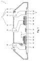
- Fig. 1 shows an inventive arrangement in an embodiment of a power semiconductor module.
- FIG. 2 shows an arrangement according to the invention in the embodiment of a single, housed power semiconductor component.
- FIG. 3 shows a three-dimensional representation of a first arrangement of a metal molding on a power semiconductor component.
- FIG. 4 shows, in a three-dimensional representation, a second arrangement of a shaped metal body on a power semiconductor component.
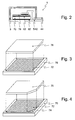
- Fig. 5 shows steps of the manufacturing method according to the invention.
- FIG. 1 shows an arrangement (1), here a power semiconductor module, having a housing (3) which has a frame-like housing part (32) and a cover (34) with latching lugs (36) for snap-latching connection to the frame-like housing part (FIG. 32).
- the frame-like housing part (32) encloses a substrate (5).
- This has an insulating body (52), preferably an insulating ceramic, such as aluminum oxide or aluminum nitrite, and on the interior of the power semiconductor module facing first major surface on a self-structured Kupferkaschtechnik.
- the individual sections of this copper lamination form the conductor tracks (54) of the power semiconductor module.
- Power semiconductor components (70), connection elements (42, 44, 46) for load connections and connecting elements (40) are arranged on these conductor tracks (54). All these components are connected by solder joints with the tracks (54).
- the load connection elements (42, 44, 46) serve for the external connection of the power semiconductor components (70)
- the connection elements (40) serve for the circuit-compatible internal connection of the power semiconductor components (70).
- This metal shaped body (76) is preferably made of copper and is provided in the region of the pressure sintered connection with a galvanically applied noble metal surface. This metal shaped body (76) is connected by soldering to a connecting element (40). This is a particular advantage of pressure sintered connections, which allow even at higher temperatures, for example in the range of 300 ° C still a permanently secure electrical connection with high mechanical stability. Thus, subsequent executed connections such as solder, bond or other pressure sintered connections with this composite of power semiconductor device (70) and metal moldings (76) are possible.
- This combination of power semiconductor component (70) and metal shaped body (76) is particularly advantageous, since the current injection into the power semiconductor component (70) takes place uniformly over the entire contact area for bonding or non-planar solder joints by means of this metal shaped body (76) and thus the power semiconductor component (FIG. 70) is loaded homogeneously over its extension, which provides improved performance and reliability.
- FIG. 2 shows an arrangement (1) according to the invention in the form of a single power semiconductor component (70), which is modeled in so-called "TO" packages by way of example.
- a substrate (5) in this case a planar metal body which is simultaneously formed as a load connection element (42), the power semiconductor component (70), a further connection element (44) and a housing covering the substrate (3).
- the substrate (5) is electrically conductively connected to the power semiconductor device (70) by means of a pressure sintered connection.
- a metal shaped body (76) is arranged on the first main surface of the power semiconductor component (70) facing away from the substrate (5).
- the second load connection element (44) is connected by means of a third pressure sintered connection or by means of a soldered or glued connection.
- FIG. 3 shows, in a three-dimensional representation, a first arrangement of a metal molding (76) on an uncontrolled power semiconductor component (70), here a power diode.
- the power diode (70) has a contact surface (72) on its first main surface.
- This contact surface (72) has a multilayer metallization structure, wherein the uppermost layer consists of a noble metal, since this is necessary for a pressure sintered connection.
- a metal shaped body (76) with the lateral expansions of the contact surface (76) is arranged on this power semiconductor component (70) for reasons of clarity, and electrically conductively connected thereto by means of a pressure sintered connection.
- the metal molding (76) is formed as a cuboid made of copper or molybdenum or of an alloy containing these two metals to at least 80 of 100 parts by volume.
- the metal moldings (76) on a noble metal layer which corresponds at least to the size of the contact surface (72) of the power semiconductor device (70).
- the entire metal moldings (76) is coated with a galvanically applied noble metal layer.
- the flat, cuboid-shaped, metal shaped body (76) has a thickness of maximum 50 of 100 of its greatest lateral extent.
- the composite of power semiconductor component (70) and arranged by means of pressure sintering metal moldings (76) can be connected in circuits with Drucktern-, solder, adhesive or other pressure sintered connections circuit.
- FIG. 4 shows, in a three-dimensional representation, a second arrangement of a shaped metal body (76) on a power semiconductor component (70), here a controlled power switch, for example an IGBT (insulated gate bipolar transistor).
- the first main surface of the power semiconductor device (70) in this case has two contact surfaces (72, 74), a large area (72) for load connection and a further contact surface (74) lesser extent to the control connection.
- the contact surface (74) for the control connection is not covered by the associated metal shaped body (76) and can thus be connected, for example, by means of wire bonding technology according to the prior art.
- the metal molding (76) is therefore formed with a recess at a corner.
- Fig. 5 shows steps of the manufacturing method according to the invention.
- the starting point here is a plurality of power semiconductor components (70) in the wafer composite on a carrier film (90) arranged in a frame (92).
- Each power semiconductor component (70) has at least one contact surface on the first main surface facing away from the carrier film. This contact surface in turn has an uppermost metallization layer of a noble metal.
- a pasty layer of a metal powder and a solvent is selectively applied to a plurality of contact surfaces of the power semiconductor components.
- spraying (80) through a spray mask or the screen printing of the paste is particularly preferred.
- the metal moldings (76) are arranged on the contact surfaces of the power semiconductor components (70). It is here particularly preferred when the metal moldings (76) in the composite, so a plurality are arranged simultaneously.
- the metal moldings (76) can be connected to each other by means of webs (78) or the metal moldings (76) themselves are also arranged on a carrier material, similar to the carrier film (90) of the power semiconductor components (70).
- the pasty layer is dried either before or after this production step of applying the metal moldings (76).
- the simultaneous pressurization (82) takes place on a plurality of power semiconductor components (70) with metal moldings (76) arranged thereon for their respective sintered connection.
- the power semiconductor components (70) with metal moldings (76) arranged thereon preferably by means of sawing, isolated (84) and by known methods (86) are removed from the carrier film and arranged by way of example in a power semiconductor module.
Landscapes
- Engineering & Computer Science (AREA)
- Microelectronics & Electronic Packaging (AREA)
- Power Engineering (AREA)
- Computer Hardware Design (AREA)
- Physics & Mathematics (AREA)
- Condensed Matter Physics & Semiconductors (AREA)
- General Physics & Mathematics (AREA)
- Manufacturing & Machinery (AREA)
- Die Bonding (AREA)
- Cooling Or The Like Of Semiconductors Or Solid State Devices (AREA)
Applications Claiming Priority (1)
| Application Number | Priority Date | Filing Date | Title |
|---|---|---|---|
| DE102005047566A DE102005047566C5 (de) | 2005-10-05 | 2005-10-05 | Anordnung mit einem Leistungshalbleiterbauelement und mit einem Gehäuse sowie Herstellungsverfahren hierzu |
Publications (3)
| Publication Number | Publication Date |
|---|---|
| EP1772900A2 true EP1772900A2 (fr) | 2007-04-11 |
| EP1772900A3 EP1772900A3 (fr) | 2008-07-16 |
| EP1772900B1 EP1772900B1 (fr) | 2012-04-25 |
Family
ID=37603438
Family Applications (1)
| Application Number | Title | Priority Date | Filing Date |
|---|---|---|---|
| EP06020799A Not-in-force EP1772900B1 (fr) | 2005-10-05 | 2006-10-04 | Procédé de fabrication d'un dispositif avec des composants semi-conducteurs de puissance incluant une étape de frittage sous pression |
Country Status (5)
| Country | Link |
|---|---|
| EP (1) | EP1772900B1 (fr) |
| JP (1) | JP5193452B2 (fr) |
| AT (1) | ATE555498T1 (fr) |
| DE (1) | DE102005047566C5 (fr) |
| DK (1) | DK1772900T3 (fr) |
Cited By (11)
| Publication number | Priority date | Publication date | Assignee | Title |
|---|---|---|---|---|
| WO2009019091A1 (fr) * | 2007-08-09 | 2009-02-12 | Robert Bosch Gmbh | Module et fabrication d'un tel module |
| EP2019421A3 (fr) * | 2007-07-26 | 2012-10-31 | SEMIKRON Elektronik GmbH & Co. KG | Dispositif semi-conducteur de puissance avec couche de contact métallique et procédé de fabrication correspondant |
| WO2013053420A1 (fr) * | 2011-10-15 | 2013-04-18 | Danfoss Silicon Power Gmbh | Puce de semi-conducteur de puissance dotée de corps moulés métalliques pour la mise en contact électrique avec de gros fils ou des bandelettes, et procédé de production |
| WO2013053419A1 (fr) * | 2011-10-15 | 2013-04-18 | Danfoss Silicon Power Gmbh | Procédé de réalisation d'une liaison entre des corps moulés métalliques et une puce de semi-conducteur de puissance, qui sont destinés à être reliés à de gros fils ou des bandelettes |
| DE102012202281A1 (de) * | 2012-02-15 | 2013-08-22 | Infineon Technologies Ag | Halbleiteranordnung für Druckkontaktierung |
| DE102012212249A1 (de) * | 2012-07-12 | 2014-01-16 | Infineon Technologies Ag | Verfahren zur Herstellung eines Verbundes und eines Halbleitermoduls |
| WO2016005146A1 (fr) * | 2014-07-11 | 2016-01-14 | Heraeus Deutschland Gmbh | Procédé de production d'un adaptateur de substrat, adaptateur de substrat et procédé d'interconnexion d'un élément semi-conducteur |
| EP3026702A1 (fr) * | 2014-11-25 | 2016-06-01 | Heraeus Deutschland GmbH & Co. KG | Procede de fabrication d'un element semi-conducteur dote d'un adaptateur de substrat, element semi-conducteur dote d'un adaptateur de substrat et procede de mise en contact d'un element semi-conducteur |
| WO2016155965A3 (fr) * | 2015-03-30 | 2016-11-24 | Robert Bosch Gmbh | Dispositif de contact et son procédé de fabrication |
| US10607962B2 (en) | 2015-08-14 | 2020-03-31 | Danfoss Silicon Power Gmbh | Method for manufacturing semiconductor chips |
| US10847494B2 (en) | 2016-10-06 | 2020-11-24 | Agile Power Switch 3D-Integration Apsi3D | Method of determining thermal impedance of a sintering layer and a measurement system |
Families Citing this family (11)
| Publication number | Priority date | Publication date | Assignee | Title |
|---|---|---|---|---|
| US8164176B2 (en) | 2006-10-20 | 2012-04-24 | Infineon Technologies Ag | Semiconductor module arrangement |
| DE102007022336A1 (de) * | 2007-05-12 | 2008-11-20 | Semikron Elektronik Gmbh & Co. Kg | Leistungshalbleitersubstrat mit Metallkontaktschicht sowie Herstellungsverfahren hierzu |
| EP2144284A1 (fr) * | 2008-07-11 | 2010-01-13 | Siemens Aktiengesellschaft | Procédé de fabrication d'un connecteur sur un élément semi-conducteur pour un distributeur d'énergie et composant électronique doté d'un connecteur fabriqué de cette manière sur un composant semi-conducteur |
| DE102008033410B4 (de) * | 2008-07-16 | 2011-06-30 | SEMIKRON Elektronik GmbH & Co. KG, 90431 | Leistungselektronische Verbindungseinrichtung mit einem Leistungshalbleiterbauelement und Herstellungsverfahren hierzu |
| DE102008055134A1 (de) * | 2008-12-23 | 2010-07-01 | Robert Bosch Gmbh | Elektrisches oder elektronisches Verbundbauteil sowie Verfahren zum Herstellen eines elektrischen oder elektronischen Verbundbauteils |
| DE102008055137A1 (de) * | 2008-12-23 | 2010-07-01 | Robert Bosch Gmbh | Elektrisches oder elektronisches Verbundbauteil sowie Verfahren zum Herstellen eines elektrischen oder elektronischen Verbundbauteils |
| JP5664028B2 (ja) * | 2010-08-31 | 2015-02-04 | 富士通株式会社 | 電子装置の製造方法 |
| DE112012007149B4 (de) | 2012-11-20 | 2020-07-09 | Denso Corporation | Halbleitervorrichtung |
| DE102014117246B4 (de) * | 2014-11-25 | 2018-11-15 | Heraeus Deutschland GmbH & Co. KG | Verfahren zum Herstellen eines Substratadapters, Substratadapter und Verfahren zum Kontaktieren eines Halbleiterelements |
| WO2018025571A1 (fr) | 2016-08-05 | 2018-02-08 | 三菱電機株式会社 | Dispositif à semi-conducteur de puissance |
| DE102016121801B4 (de) * | 2016-11-14 | 2022-03-17 | Infineon Technologies Ag | Baugruppe mit Verbindungen, die verschiedene Schmelztemperaturen aufweisen, Fahrzeug mit der Baugruppe und Verfahren zum Herstellen derselben und Verwendung der Baugruppe für eine Automobilanwendung |
Citations (1)
| Publication number | Priority date | Publication date | Assignee | Title |
|---|---|---|---|---|
| US5499178A (en) | 1991-12-16 | 1996-03-12 | Regents Of The University Of Minnesota | System for reducing harmonics by harmonic current injection |
Family Cites Families (15)
| Publication number | Priority date | Publication date | Assignee | Title |
|---|---|---|---|---|
| NL135880C (fr) * | 1961-07-12 | 1900-01-01 | ||
| DE3414065A1 (de) * | 1984-04-13 | 1985-12-12 | Siemens AG, 1000 Berlin und 8000 München | Anordnung bestehend aus mindestens einem auf einem substrat befestigten elektronischen bauelement und verfahren zur herstellung einer derartigen anordnung |
| DE4040753A1 (de) * | 1990-12-19 | 1992-06-25 | Siemens Ag | Leistungshalbleiterbauelement |
| DE59100737D1 (de) * | 1991-05-15 | 1994-01-27 | Abb Ixys Semiconductor Gmbh | Leistungshalbleitermodul und Verfahren zur Herstellung eines solchen Moduls. |
| DE4300516C2 (de) * | 1993-01-12 | 2001-05-17 | Ixys Semiconductor Gmbh | Leistungshalbleitermodul |
| DE19612838A1 (de) * | 1995-11-13 | 1997-05-15 | Asea Brown Boveri | Leistungshalbleiterbauelement sowie Verfahren zu dessen Herstellung |
| DE19719703C5 (de) * | 1997-05-09 | 2005-11-17 | eupec Europäische Gesellschaft für Leistungshalbleiter mbH & Co. KG | Leistungshalbleitermodul mit Keramiksubstrat |
| JP3220900B2 (ja) * | 1997-06-24 | 2001-10-22 | 三菱電機株式会社 | パワー半導体モジュール |
| DE19739684B4 (de) * | 1997-09-10 | 2006-04-13 | Robert Bosch Gmbh | Verfahren zur Herstellung von Chipstapeln |
| DE10062108B4 (de) * | 2000-12-13 | 2010-04-15 | Infineon Technologies Ag | Leistungsmodul mit verbessertem transienten Wärmewiderstand |
| DE10222609B4 (de) * | 2002-04-15 | 2008-07-10 | Schott Ag | Verfahren zur Herstellung strukturierter Schichten auf Substraten und verfahrensgemäß beschichtetes Substrat |
| DE10303103B4 (de) * | 2003-01-28 | 2009-07-09 | Ixys Semiconductor Gmbh | Halbleiterbauteil, insbesondere Leistungshalbleiterbauteil |
| DE10360573B4 (de) * | 2003-12-22 | 2008-02-14 | Infineon Technologies Ag | Leistungshalbleitermodul |
| DE102004019567B3 (de) * | 2004-04-22 | 2006-01-12 | Semikron Elektronik Gmbh & Co. Kg | Verfahren zur Befestigung von elektronischen Bauelementen auf einem Substrat |
| DE102004056702B3 (de) * | 2004-04-22 | 2006-03-02 | Semikron Elektronik Gmbh & Co. Kg | Verfahren zur Befestigung von elektronischen Bauelementen auf einem Substrat |
-
2005
- 2005-10-05 DE DE102005047566A patent/DE102005047566C5/de not_active Expired - Fee Related
-
2006
- 2006-10-04 JP JP2006272883A patent/JP5193452B2/ja not_active Expired - Fee Related
- 2006-10-04 DK DK06020799.0T patent/DK1772900T3/da active
- 2006-10-04 EP EP06020799A patent/EP1772900B1/fr not_active Not-in-force
- 2006-10-04 AT AT06020799T patent/ATE555498T1/de active
Patent Citations (1)
| Publication number | Priority date | Publication date | Assignee | Title |
|---|---|---|---|---|
| US5499178A (en) | 1991-12-16 | 1996-03-12 | Regents Of The University Of Minnesota | System for reducing harmonics by harmonic current injection |
Cited By (21)
| Publication number | Priority date | Publication date | Assignee | Title |
|---|---|---|---|---|
| EP2019421A3 (fr) * | 2007-07-26 | 2012-10-31 | SEMIKRON Elektronik GmbH & Co. KG | Dispositif semi-conducteur de puissance avec couche de contact métallique et procédé de fabrication correspondant |
| US8552306B2 (en) | 2007-08-09 | 2013-10-08 | Robert Bosch Gmbh | Assembly and production of an assembly |
| WO2009019091A1 (fr) * | 2007-08-09 | 2009-02-12 | Robert Bosch Gmbh | Module et fabrication d'un tel module |
| US9233436B2 (en) | 2007-08-09 | 2016-01-12 | Robert Bosch Gmbh | Assembly and production of an assembly |
| WO2013053419A1 (fr) * | 2011-10-15 | 2013-04-18 | Danfoss Silicon Power Gmbh | Procédé de réalisation d'une liaison entre des corps moulés métalliques et une puce de semi-conducteur de puissance, qui sont destinés à être reliés à de gros fils ou des bandelettes |
| CN103875067A (zh) * | 2011-10-15 | 2014-06-18 | 丹佛斯硅动力股份有限公司 | 在金属成型体和结合到厚布线或条片用的功率半导体间形成连接的方法 |
| CN103890924A (zh) * | 2011-10-15 | 2014-06-25 | 丹佛斯硅动力股份有限公司 | 具有用于接触厚布线或条片的金属成型体的功率半导体芯片及其制造方法 |
| CN103890924B (zh) * | 2011-10-15 | 2017-02-15 | 丹佛斯硅动力股份有限公司 | 具有用于接触厚布线或条片的金属成型体的功率半导体芯片及其制造方法 |
| WO2013053420A1 (fr) * | 2011-10-15 | 2013-04-18 | Danfoss Silicon Power Gmbh | Puce de semi-conducteur de puissance dotée de corps moulés métalliques pour la mise en contact électrique avec de gros fils ou des bandelettes, et procédé de production |
| US9318421B2 (en) | 2011-10-15 | 2016-04-19 | Danfoss Silicon Power Gmbh | Power semiconductor chip with a metallic moulded body for contacting thick wires or strips and method for the production thereof |
| CN103875067B (zh) * | 2011-10-15 | 2018-02-13 | 丹佛斯硅动力股份有限公司 | 在金属成型体和结合到厚布线或条片用的功率半导体间形成连接的方法 |
| US9786627B2 (en) | 2011-10-15 | 2017-10-10 | Danfoss Silicon Power Gmbh | Method for creating a connection between metallic moulded bodies and a power semiconductor which is used to bond to thick wires or strips |
| DE102012202281A1 (de) * | 2012-02-15 | 2013-08-22 | Infineon Technologies Ag | Halbleiteranordnung für Druckkontaktierung |
| DE102012212249A1 (de) * | 2012-07-12 | 2014-01-16 | Infineon Technologies Ag | Verfahren zur Herstellung eines Verbundes und eines Halbleitermoduls |
| DE102012212249B4 (de) * | 2012-07-12 | 2016-02-25 | Infineon Technologies Ag | Verfahren zur Herstellung eines Verbundes und eines Halbleitermoduls |
| WO2016005146A1 (fr) * | 2014-07-11 | 2016-01-14 | Heraeus Deutschland Gmbh | Procédé de production d'un adaptateur de substrat, adaptateur de substrat et procédé d'interconnexion d'un élément semi-conducteur |
| CN105632951A (zh) * | 2014-11-25 | 2016-06-01 | 贺利氏德国有限及两合公司 | 具有衬底适配器的半导体元件及其制造方法和其接触方法 |
| EP3026702A1 (fr) * | 2014-11-25 | 2016-06-01 | Heraeus Deutschland GmbH & Co. KG | Procede de fabrication d'un element semi-conducteur dote d'un adaptateur de substrat, element semi-conducteur dote d'un adaptateur de substrat et procede de mise en contact d'un element semi-conducteur |
| WO2016155965A3 (fr) * | 2015-03-30 | 2016-11-24 | Robert Bosch Gmbh | Dispositif de contact et son procédé de fabrication |
| US10607962B2 (en) | 2015-08-14 | 2020-03-31 | Danfoss Silicon Power Gmbh | Method for manufacturing semiconductor chips |
| US10847494B2 (en) | 2016-10-06 | 2020-11-24 | Agile Power Switch 3D-Integration Apsi3D | Method of determining thermal impedance of a sintering layer and a measurement system |
Also Published As
| Publication number | Publication date |
|---|---|
| JP2007103949A (ja) | 2007-04-19 |
| JP5193452B2 (ja) | 2013-05-08 |
| EP1772900B1 (fr) | 2012-04-25 |
| EP1772900A3 (fr) | 2008-07-16 |
| DE102005047566B4 (de) | 2009-05-14 |
| ATE555498T1 (de) | 2012-05-15 |
| DK1772900T3 (da) | 2012-07-23 |
| DE102005047566A1 (de) | 2007-04-12 |
| DE102005047566C5 (de) | 2011-06-09 |
Similar Documents
| Publication | Publication Date | Title |
|---|---|---|
| EP1772900B1 (fr) | Procédé de fabrication d'un dispositif avec des composants semi-conducteurs de puissance incluant une étape de frittage sous pression | |
| DE112014001487B4 (de) | Halbleitermodul | |
| DE102009044641B4 (de) | Einrichtung mit einem Halbleiterchip und Metallfolie sowie ein Verfahren zur Herstellung der Einrichtung | |
| EP1772902B1 (fr) | Module semiconducteur de puissance avec couche isolante intermédiaire et méthode de fabrication | |
| DE102009017853B4 (de) | Verfahren zur Herstellung einer Halbleitervorrichtung | |
| DE102009039227B4 (de) | Verfahren zur Herstellung eines Halbleiterbauelements | |
| EP1956647A1 (fr) | Installation de commutation dotée d'un dispositif de liaison et son procédé de fabrication | |
| DE102010037439B4 (de) | Bauelement mit einem Halbleiterchip und einem Träger und Fabrikationsverfahren | |
| DE102016206542B4 (de) | Verfahren zum Herstellen einer Halbleitervorrichtung | |
| WO2006021191A1 (fr) | Composant a semiconducteurs a conducteurs plats pourvu d'une puce de semiconducteur | |
| DE102009000587A1 (de) | Modul mit einer gesinterten Verbindung zwischen einem Halbleiterchip und einer Kupferoberfläche und Verfahren zur Herstellung eines Moduls mit einer gesinterten Verbindung zwischen einem Halbleiterchip und einer Kupferoberfläche | |
| DE102009026480A1 (de) | Modul mit einer gesinterten Fügestelle | |
| DE102015109186A1 (de) | Halbleiteranordnung, Halbleitersystem und Verfahren zur Ausbildung einer Halbleiteranordnung | |
| DE102009018541A1 (de) | Kontaktierungsmittel und Verfahren zur Kontaktierung elektrischer Bauteile | |
| DE102004057421B4 (de) | Druckkontaktiertes Leistungshalbleitermodul für hohe Umgebungstemperaturen und Verfahren zu seiner Herstellung | |
| DE102005050534B4 (de) | Leistungshalbleitermodul | |
| DE102015107109B4 (de) | Elektronische Vorrichtung mit einem Metallsubstrat und einem in einem Laminat eingebetteten Halbleitermodul | |
| EP3300105B1 (fr) | Module semi-conducteur de puissance et procédé de fabrication d'un module semi-conducteur de puissance | |
| EP1993132A2 (fr) | Substrat semi-conducteur de puissance doté d'une couche de contact métallique et procédé de fabrication associé | |
| DE102014105367B4 (de) | Pressmasse und Verfahren zum Verpacken von Halbleiterchips | |
| DE102014203306A1 (de) | Herstellen eines Elektronikmoduls | |
| WO2018037047A1 (fr) | Module de puissance, procédé de fabrication et circuit électronique de puissance | |
| DE102008040290A1 (de) | Hybridschaltungsstruktur mit keramischen Schaltungsträgern | |
| DE102005024096A1 (de) | Vorrichtung und Verfahren zur Montage elektrischer Bauteile | |
| DE102021116053A1 (de) | Elektrischer Leiter, elektronische Baugruppe mit elektrischem Leiter und Verfahren zum Herstellen einer elektronischen Baugruppe mit einem elektrischen Leiter |
Legal Events
| Date | Code | Title | Description |
|---|---|---|---|
| PUAI | Public reference made under article 153(3) epc to a published international application that has entered the european phase |
Free format text: ORIGINAL CODE: 0009012 |
|
| AK | Designated contracting states |
Kind code of ref document: A2 Designated state(s): AT BE BG CH CY CZ DE DK EE ES FI FR GB GR HU IE IS IT LI LT LU LV MC NL PL PT RO SE SI SK TR |
|
| AX | Request for extension of the european patent |
Extension state: AL BA HR MK YU |
|
| PUAL | Search report despatched |
Free format text: ORIGINAL CODE: 0009013 |
|
| AK | Designated contracting states |
Kind code of ref document: A3 Designated state(s): AT BE BG CH CY CZ DE DK EE ES FI FR GB GR HU IE IS IT LI LT LU LV MC NL PL PT RO SE SI SK TR |
|
| AX | Request for extension of the european patent |
Extension state: AL BA HR MK RS |
|
| RIC1 | Information provided on ipc code assigned before grant |
Ipc: H01L 21/60 20060101AFI20070122BHEP Ipc: H01L 23/492 20060101ALI20080606BHEP Ipc: H01L 25/07 20060101ALI20080606BHEP |
|
| 17P | Request for examination filed |
Effective date: 20080707 |
|
| 17Q | First examination report despatched |
Effective date: 20080826 |
|
| AKX | Designation fees paid |
Designated state(s): AT BE BG CH CY CZ DE DK EE ES FI FR GB GR HU IE IS IT LI LT LU LV MC NL PL PT RO SE SI SK TR |
|
| REG | Reference to a national code |
Ref country code: DE Ref legal event code: R079 Ref document number: 502006011340 Country of ref document: DE Free format text: PREVIOUS MAIN CLASS: H01L0021600000 Ipc: H01L0021980000 |
|
| RIC1 | Information provided on ipc code assigned before grant |
Ipc: H01L 25/07 20060101ALI20111114BHEP Ipc: H01L 23/492 20060101ALI20111114BHEP Ipc: H01L 21/60 20060101ALI20111114BHEP Ipc: H01L 21/98 20060101AFI20111114BHEP |
|
| RTI1 | Title (correction) |
Free format text: FABRICATION METHOD OF A DEVICE WITH POWER SEMICONDUCTOR COMPONENTS INCLUDING A PRESSURE SINTERING STEP |
|
| GRAP | Despatch of communication of intention to grant a patent |
Free format text: ORIGINAL CODE: EPIDOSNIGR1 |
|
| GRAS | Grant fee paid |
Free format text: ORIGINAL CODE: EPIDOSNIGR3 |
|
| GRAA | (expected) grant |
Free format text: ORIGINAL CODE: 0009210 |
|
| AK | Designated contracting states |
Kind code of ref document: B1 Designated state(s): AT BE BG CH CY CZ DE DK EE ES FI FR GB GR HU IE IS IT LI LT LU LV MC NL PL PT RO SE SI SK TR |
|
| REG | Reference to a national code |
Ref country code: GB Ref legal event code: FG4D Free format text: NOT ENGLISH |
|
| REG | Reference to a national code |
Ref country code: CH Ref legal event code: EP |
|
| REG | Reference to a national code |
Ref country code: CH Ref legal event code: NV Representative=s name: BRAUNPAT BRAUN EDER AG Ref country code: AT Ref legal event code: REF Ref document number: 555498 Country of ref document: AT Kind code of ref document: T Effective date: 20120515 |
|
| REG | Reference to a national code |
Ref country code: IE Ref legal event code: FG4D Free format text: LANGUAGE OF EP DOCUMENT: GERMAN |
|
| REG | Reference to a national code |
Ref country code: DE Ref legal event code: R096 Ref document number: 502006011340 Country of ref document: DE Effective date: 20120614 |
|
| REG | Reference to a national code |
Ref country code: DK Ref legal event code: T3 |
|
| REG | Reference to a national code |
Ref country code: SE Ref legal event code: TRGR |
|
| REG | Reference to a national code |
Ref country code: NL Ref legal event code: VDEP Effective date: 20120425 |
|
| REG | Reference to a national code |
Ref country code: SK Ref legal event code: T3 Ref document number: E 11879 Country of ref document: SK |
|
| LTIE | Lt: invalidation of european patent or patent extension |
Effective date: 20120425 |
|
| PG25 | Lapsed in a contracting state [announced via postgrant information from national office to epo] |
Ref country code: FI Free format text: LAPSE BECAUSE OF FAILURE TO SUBMIT A TRANSLATION OF THE DESCRIPTION OR TO PAY THE FEE WITHIN THE PRESCRIBED TIME-LIMIT Effective date: 20120425 Ref country code: CY Free format text: LAPSE BECAUSE OF FAILURE TO SUBMIT A TRANSLATION OF THE DESCRIPTION OR TO PAY THE FEE WITHIN THE PRESCRIBED TIME-LIMIT Effective date: 20120425 Ref country code: IS Free format text: LAPSE BECAUSE OF FAILURE TO SUBMIT A TRANSLATION OF THE DESCRIPTION OR TO PAY THE FEE WITHIN THE PRESCRIBED TIME-LIMIT Effective date: 20120825 Ref country code: LT Free format text: LAPSE BECAUSE OF FAILURE TO SUBMIT A TRANSLATION OF THE DESCRIPTION OR TO PAY THE FEE WITHIN THE PRESCRIBED TIME-LIMIT Effective date: 20120425 Ref country code: PL Free format text: LAPSE BECAUSE OF FAILURE TO SUBMIT A TRANSLATION OF THE DESCRIPTION OR TO PAY THE FEE WITHIN THE PRESCRIBED TIME-LIMIT Effective date: 20120425 |
|
| PG25 | Lapsed in a contracting state [announced via postgrant information from national office to epo] |
Ref country code: SI Free format text: LAPSE BECAUSE OF FAILURE TO SUBMIT A TRANSLATION OF THE DESCRIPTION OR TO PAY THE FEE WITHIN THE PRESCRIBED TIME-LIMIT Effective date: 20120425 Ref country code: GR Free format text: LAPSE BECAUSE OF FAILURE TO SUBMIT A TRANSLATION OF THE DESCRIPTION OR TO PAY THE FEE WITHIN THE PRESCRIBED TIME-LIMIT Effective date: 20120726 Ref country code: PT Free format text: LAPSE BECAUSE OF FAILURE TO SUBMIT A TRANSLATION OF THE DESCRIPTION OR TO PAY THE FEE WITHIN THE PRESCRIBED TIME-LIMIT Effective date: 20120827 Ref country code: LV Free format text: LAPSE BECAUSE OF FAILURE TO SUBMIT A TRANSLATION OF THE DESCRIPTION OR TO PAY THE FEE WITHIN THE PRESCRIBED TIME-LIMIT Effective date: 20120425 |
|
| PG25 | Lapsed in a contracting state [announced via postgrant information from national office to epo] |
Ref country code: EE Free format text: LAPSE BECAUSE OF FAILURE TO SUBMIT A TRANSLATION OF THE DESCRIPTION OR TO PAY THE FEE WITHIN THE PRESCRIBED TIME-LIMIT Effective date: 20120425 Ref country code: NL Free format text: LAPSE BECAUSE OF FAILURE TO SUBMIT A TRANSLATION OF THE DESCRIPTION OR TO PAY THE FEE WITHIN THE PRESCRIBED TIME-LIMIT Effective date: 20120425 Ref country code: CZ Free format text: LAPSE BECAUSE OF FAILURE TO SUBMIT A TRANSLATION OF THE DESCRIPTION OR TO PAY THE FEE WITHIN THE PRESCRIBED TIME-LIMIT Effective date: 20120425 Ref country code: RO Free format text: LAPSE BECAUSE OF FAILURE TO SUBMIT A TRANSLATION OF THE DESCRIPTION OR TO PAY THE FEE WITHIN THE PRESCRIBED TIME-LIMIT Effective date: 20120425 |
|
| PG25 | Lapsed in a contracting state [announced via postgrant information from national office to epo] |
Ref country code: IT Free format text: LAPSE BECAUSE OF FAILURE TO SUBMIT A TRANSLATION OF THE DESCRIPTION OR TO PAY THE FEE WITHIN THE PRESCRIBED TIME-LIMIT Effective date: 20120425 |
|
| PLBE | No opposition filed within time limit |
Free format text: ORIGINAL CODE: 0009261 |
|
| STAA | Information on the status of an ep patent application or granted ep patent |
Free format text: STATUS: NO OPPOSITION FILED WITHIN TIME LIMIT |
|
| 26N | No opposition filed |
Effective date: 20130128 |
|
| BERE | Be: lapsed |
Owner name: SEMIKRON ELEKTRONIK G.M.B.H. & CO. KG PATENTABTEI Effective date: 20121031 |
|
| PG25 | Lapsed in a contracting state [announced via postgrant information from national office to epo] |
Ref country code: ES Free format text: LAPSE BECAUSE OF FAILURE TO SUBMIT A TRANSLATION OF THE DESCRIPTION OR TO PAY THE FEE WITHIN THE PRESCRIBED TIME-LIMIT Effective date: 20120805 |
|
| REG | Reference to a national code |
Ref country code: DE Ref legal event code: R097 Ref document number: 502006011340 Country of ref document: DE Effective date: 20130128 |
|
| PG25 | Lapsed in a contracting state [announced via postgrant information from national office to epo] |
Ref country code: MC Free format text: LAPSE BECAUSE OF NON-PAYMENT OF DUE FEES Effective date: 20121031 |
|
| REG | Reference to a national code |
Ref country code: IE Ref legal event code: MM4A |
|
| PG25 | Lapsed in a contracting state [announced via postgrant information from national office to epo] |
Ref country code: BE Free format text: LAPSE BECAUSE OF NON-PAYMENT OF DUE FEES Effective date: 20121031 Ref country code: IE Free format text: LAPSE BECAUSE OF NON-PAYMENT OF DUE FEES Effective date: 20121004 Ref country code: BG Free format text: LAPSE BECAUSE OF FAILURE TO SUBMIT A TRANSLATION OF THE DESCRIPTION OR TO PAY THE FEE WITHIN THE PRESCRIBED TIME-LIMIT Effective date: 20120725 |
|
| REG | Reference to a national code |
Ref country code: AT Ref legal event code: MM01 Ref document number: 555498 Country of ref document: AT Kind code of ref document: T Effective date: 20121031 |
|
| PG25 | Lapsed in a contracting state [announced via postgrant information from national office to epo] |
Ref country code: AT Free format text: LAPSE BECAUSE OF NON-PAYMENT OF DUE FEES Effective date: 20121031 |
|
| PG25 | Lapsed in a contracting state [announced via postgrant information from national office to epo] |
Ref country code: TR Free format text: LAPSE BECAUSE OF FAILURE TO SUBMIT A TRANSLATION OF THE DESCRIPTION OR TO PAY THE FEE WITHIN THE PRESCRIBED TIME-LIMIT Effective date: 20120425 |
|
| PG25 | Lapsed in a contracting state [announced via postgrant information from national office to epo] |
Ref country code: LU Free format text: LAPSE BECAUSE OF NON-PAYMENT OF DUE FEES Effective date: 20121004 |
|
| PG25 | Lapsed in a contracting state [announced via postgrant information from national office to epo] |
Ref country code: HU Free format text: LAPSE BECAUSE OF FAILURE TO SUBMIT A TRANSLATION OF THE DESCRIPTION OR TO PAY THE FEE WITHIN THE PRESCRIBED TIME-LIMIT Effective date: 20061004 |
|
| REG | Reference to a national code |
Ref country code: FR Ref legal event code: PLFP Year of fee payment: 10 |
|
| REG | Reference to a national code |
Ref country code: FR Ref legal event code: PLFP Year of fee payment: 11 |
|
| PGFP | Annual fee paid to national office [announced via postgrant information from national office to epo] |
Ref country code: SK Payment date: 20160928 Year of fee payment: 11 |
|
| PGFP | Annual fee paid to national office [announced via postgrant information from national office to epo] |
Ref country code: SE Payment date: 20161025 Year of fee payment: 11 |
|
| REG | Reference to a national code |
Ref country code: FR Ref legal event code: PLFP Year of fee payment: 12 |
|
| REG | Reference to a national code |
Ref country code: CH Ref legal event code: PCAR Free format text: NEW ADDRESS: HOLEESTRASSE 87, 4054 BASEL (CH) |
|
| REG | Reference to a national code |
Ref country code: SE Ref legal event code: EUG |
|
| REG | Reference to a national code |
Ref country code: SK Ref legal event code: MM4A Ref document number: E 11879 Country of ref document: SK Effective date: 20171004 |
|
| PG25 | Lapsed in a contracting state [announced via postgrant information from national office to epo] |
Ref country code: SK Free format text: LAPSE BECAUSE OF NON-PAYMENT OF DUE FEES Effective date: 20171004 |
|
| PG25 | Lapsed in a contracting state [announced via postgrant information from national office to epo] |
Ref country code: SE Free format text: LAPSE BECAUSE OF NON-PAYMENT OF DUE FEES Effective date: 20171005 |
|
| REG | Reference to a national code |
Ref country code: FR Ref legal event code: PLFP Year of fee payment: 13 |
|
| PGFP | Annual fee paid to national office [announced via postgrant information from national office to epo] |
Ref country code: GB Payment date: 20211022 Year of fee payment: 16 Ref country code: DK Payment date: 20211021 Year of fee payment: 16 Ref country code: DE Payment date: 20211031 Year of fee payment: 16 |
|
| PGFP | Annual fee paid to national office [announced via postgrant information from national office to epo] |
Ref country code: FR Payment date: 20211022 Year of fee payment: 16 Ref country code: CH Payment date: 20211022 Year of fee payment: 16 |
|
| REG | Reference to a national code |
Ref country code: DE Ref legal event code: R119 Ref document number: 502006011340 Country of ref document: DE |
|
| REG | Reference to a national code |
Ref country code: DK Ref legal event code: EBP Effective date: 20221031 |
|
| REG | Reference to a national code |
Ref country code: CH Ref legal event code: PL |
|
| GBPC | Gb: european patent ceased through non-payment of renewal fee |
Effective date: 20221004 |
|
| PG25 | Lapsed in a contracting state [announced via postgrant information from national office to epo] |
Ref country code: LI Free format text: LAPSE BECAUSE OF NON-PAYMENT OF DUE FEES Effective date: 20221031 Ref country code: FR Free format text: LAPSE BECAUSE OF NON-PAYMENT OF DUE FEES Effective date: 20221031 Ref country code: DE Free format text: LAPSE BECAUSE OF NON-PAYMENT OF DUE FEES Effective date: 20230503 Ref country code: CH Free format text: LAPSE BECAUSE OF NON-PAYMENT OF DUE FEES Effective date: 20221031 |
|
| PG25 | Lapsed in a contracting state [announced via postgrant information from national office to epo] |
Ref country code: GB Free format text: LAPSE BECAUSE OF NON-PAYMENT OF DUE FEES Effective date: 20221004 Ref country code: DK Free format text: LAPSE BECAUSE OF NON-PAYMENT OF DUE FEES Effective date: 20221031 |