EP1769876B1 - Reibrührpunktschweissverfahren und -vorrichtung mit einem einen einschränkenden Teil aufweisenden Behalter - Google Patents
Reibrührpunktschweissverfahren und -vorrichtung mit einem einen einschränkenden Teil aufweisenden Behalter Download PDFInfo
- Publication number
- EP1769876B1 EP1769876B1 EP06019390A EP06019390A EP1769876B1 EP 1769876 B1 EP1769876 B1 EP 1769876B1 EP 06019390 A EP06019390 A EP 06019390A EP 06019390 A EP06019390 A EP 06019390A EP 1769876 B1 EP1769876 B1 EP 1769876B1
- Authority
- EP
- European Patent Office
- Prior art keywords
- tool
- rotating tool
- joining
- metal members
- metal
- Prior art date
- Legal status (The legal status is an assumption and is not a legal conclusion. Google has not performed a legal analysis and makes no representation as to the accuracy of the status listed.)
- Expired - Fee Related
Links
Images


Classifications
-
- B—PERFORMING OPERATIONS; TRANSPORTING
- B23—MACHINE TOOLS; METAL-WORKING NOT OTHERWISE PROVIDED FOR
- B23K—SOLDERING OR UNSOLDERING; WELDING; CLADDING OR PLATING BY SOLDERING OR WELDING; CUTTING BY APPLYING HEAT LOCALLY, e.g. FLAME CUTTING; WORKING BY LASER BEAM
- B23K20/00—Non-electric welding by applying impact or other pressure, with or without the application of heat, e.g. cladding or plating
- B23K20/12—Non-electric welding by applying impact or other pressure, with or without the application of heat, e.g. cladding or plating the heat being generated by friction; Friction welding
- B23K20/122—Non-electric welding by applying impact or other pressure, with or without the application of heat, e.g. cladding or plating the heat being generated by friction; Friction welding using a non-consumable tool, e.g. friction stir welding
- B23K20/1265—Non-butt welded joints, e.g. overlap-joints, T-joints or spot welds
-
- B—PERFORMING OPERATIONS; TRANSPORTING
- B23—MACHINE TOOLS; METAL-WORKING NOT OTHERWISE PROVIDED FOR
- B23K—SOLDERING OR UNSOLDERING; WELDING; CLADDING OR PLATING BY SOLDERING OR WELDING; CUTTING BY APPLYING HEAT LOCALLY, e.g. FLAME CUTTING; WORKING BY LASER BEAM
- B23K20/00—Non-electric welding by applying impact or other pressure, with or without the application of heat, e.g. cladding or plating
- B23K20/12—Non-electric welding by applying impact or other pressure, with or without the application of heat, e.g. cladding or plating the heat being generated by friction; Friction welding
- B23K20/122—Non-electric welding by applying impact or other pressure, with or without the application of heat, e.g. cladding or plating the heat being generated by friction; Friction welding using a non-consumable tool, e.g. friction stir welding
- B23K20/1245—Non-electric welding by applying impact or other pressure, with or without the application of heat, e.g. cladding or plating the heat being generated by friction; Friction welding using a non-consumable tool, e.g. friction stir welding characterised by the apparatus
- B23K20/125—Rotary tool drive mechanism
-
- B—PERFORMING OPERATIONS; TRANSPORTING
- B23—MACHINE TOOLS; METAL-WORKING NOT OTHERWISE PROVIDED FOR
- B23K—SOLDERING OR UNSOLDERING; WELDING; CLADDING OR PLATING BY SOLDERING OR WELDING; CUTTING BY APPLYING HEAT LOCALLY, e.g. FLAME CUTTING; WORKING BY LASER BEAM
- B23K20/00—Non-electric welding by applying impact or other pressure, with or without the application of heat, e.g. cladding or plating
- B23K20/12—Non-electric welding by applying impact or other pressure, with or without the application of heat, e.g. cladding or plating the heat being generated by friction; Friction welding
- B23K20/122—Non-electric welding by applying impact or other pressure, with or without the application of heat, e.g. cladding or plating the heat being generated by friction; Friction welding using a non-consumable tool, e.g. friction stir welding
- B23K20/1245—Non-electric welding by applying impact or other pressure, with or without the application of heat, e.g. cladding or plating the heat being generated by friction; Friction welding using a non-consumable tool, e.g. friction stir welding characterised by the apparatus
- B23K20/126—Workpiece support, i.e. backing or clamping
Definitions
- the present invention relates to a frictional spot joining method and apparatus according to the preamble of, respectively, claims 1 and 5 (see, for example, JP 2004/167511 A ), in which a plurality of metal members are provided to at least partly lap over and these metal members are joined with a frictional heat by a rotating tool.
- a frictional spot joining is known as an appropriate joining method that can be applied with reasonably low costs.
- a plurality of metal members are provided to lap over, a rotating tool is pushed against the metal members such that the metal member is softened and made in a plastic flow state by a frictional heat, whereby the metal members can be joined in a solid state (joining in a slid state without melting) with a temperature lower than a melting point of a work to be joined (metal members).
- EP Patent Application Publication No. 1498210 A1 discloses a frictional spot joining method and apparatus for a zinc-plating steel plate and an aluminum plate.
- This apparatus comprises a joining device that integrally has a rotating tool, a receiving tool that is disposed to face the rotating tool on a rotational axis of the rotating tool, and a drive device operative to rotate and move the rotating tool in a pushing direction.
- a rotational runout of the rotating tool tends to occur when a tip (shoulder portion) of the rotating tool contacts a work in this frictional spot joining.
- a continuous movement of the receiving tool in a direction that is at an angle different from 0° or 180°, preferably substantially perpendicular to the rotational axis of the rotating tool tends to occur due to a rapid increase of the contact resistance.
- a projection (pin) with a smaller diameter is formed at the shoulder portion in order to restrain the above-described rotational runout.
- the pin contacts first with a small contact resistance at the joining, thereby providing a proper centering (anchor function).
- the rotational runout can be restrained by this anchor function.
- Japanese Patent Laid-Open Publication No. 2003-205374 discloses a frictional spot joining device equipped with a fixing device having a spring and a pressing member that are provided around the rotating tool, which is operative to restrain the rotational runout (corresponding to a lateral runout in this publicaiton).
- the pressing member of this fixing device is a substantially cylindrical member that is provided coaxially outside the rotating tool, which restrains via a bearing a movement of the rotating member in a direction that is perpendicular to the rotational axis of the rotating member. And, when the joining is executed, this member contacts the work first, prior to the rotating member contacting the work, and is pressed against the work by the spring.
- the work and pressing member are integrated temporarily, so the movement of the rotating tool in the direction perpendicular to the rotational axis relative to the work is restrained via the bearing. Namely, the rotational runout can be restrained.
- the fixing device shown in the above-described latter publication comprises the spring, bearing and so on, therefore its structure would be rather complicated. Also, its size would be relatively large so as to enclose the rotating tool, so that the joining in a narrow space would be difficult. In fact, the rotating tool is required to go through a narrow gap space between clamping tools fixing the work and approach to the work, so a large-sized device would be inappropriate.
- Document JP 2004/167511 discloses a friction stir joining apparatus and a method therefor.
- the apparatus comprises a joining tool, a backing tool, and a clamping member.
- Document JP 2004/167510 A discloses a holding apparatus for a friction stir joining apparatus.
- the apparatus comprises two holding parts, which hold the objects to be joined, a joining tool and a backing member.
- the holding parts can move the objects to be joined such that the joining tool does not abut on the objects to be joined prior to the baking member.
- Document US 2004/0079787 discloses a discontinuous friction stir welding apparatus and welding method.
- the tool, a moving mechanism of the tool and a backing member for the welded material are received in one frame.
- the tool has a pin portion with a small diameter in a leading end of a shoulder portion with a large diameter protruding in axial direction.
- the welding is carried out by moving only said tool in a weld line direction of the welded material without moving said frame.
- the present invention has been devised in view of the above-described problem, and an object of the present invention is to provide a frictional spot joining method and apparatus that allows a more effective and better joining.
- An object of the present invention is to provide a frictional spot joining method and apparatus that can restrain the rotational runout (movement) of the rotating tool effectively with a simple structure of properly small-sized rotating tool and receiving tool.
- a frictional spot joining method in which a plurality of metal members that at least partly lap over are jointed with a joining device that (preferably integrally) has a rotating tool, a receiving tool that is disposed to substantially face the rotating tool substantially on a rotational axis of the rotating tool and a drive device operative to rotate and move the rotating tool in a pushing direction substantially toward the metal members, the metal members at least partly lapping over being located between the rotating tool and the receiving tool of the joining device when being joined, the rotating tool being configured to be pushed against one of the metal members such that at least the one of the metal members is softened and made in a plastic flow state by a frictional heat generated by the rotating tool, the method comprising a step of providing a holding member to be located on a side of the receiving tool when the metal members are joined, the holding member having a restriction portion that is operative to restrain a movement of the receiving tool in a direction that is at an angle different from 0° or 180°, preferably substantially perpen
- the rotational runout of the rotating tool occurring would cause a vibration of the entire joining device. And, this vibration would be transmitted to the receiving tool integrally provided at the joining device as well. Namely, once the rotational runout occurs at the rotating tool, the vibration (runout) of the receiving tool would occur in the direction perpendicular to the rotational axis of the rotating tool.
- this runout of the receiving tool can be restrained properly by the restriction portion of the holding member of the present invention. And, the runout of the rotating tool can be also restrained properly with a reaction function of this restraint of the receiving tool by the holding member.
- the receiving tool since the receiving tool needs not to rotate, there is no need for providing a bearing member to restrain the runout of the receiving tool. Also, since the receiving tool is generally used in such a manner that it contacts the work prior to contacting of the rotating tool with the work, there may be no need for providing additional members such as springs to press it against the work. Further, since the holding member is provided beside or adjacent to the work, it may be unnecessary for any additional member to be provided at the rotating tool or the receiving tool. Accordingly, properly small-sized tools can be obtained.
- the present invention can restrain the rotational runout of the rotating tool effectively by the simple structure with the properly small-sized rotating tool and receiving tool.
- the restraint of the rotational runout can also prevent the adhesion of the work to the shoulder portion of the rotating tool.
- promotion of the rotational runout, decrease of joining quality, any damage of the rotating tool, its drive mechanism and/or clamping tool can be avoided properly.
- a frictional spot joining apparatus in which a plurality of metal members that at least partly lap over are jointed with a joining device that (preferably integrally) has a rotating tool, a receiving tool that is disposed to substantially face the rotating tool substantially on a rotational axis of the rotating tool and a drive device operative to rotate and move the rotating tool in a pushing direction substantially toward the metal members, the metal members at least partly lapping over being located between the rotating tool and the receiving tool of the joining device when being joined, the rotating tool being configured to be pushed against one of the metal members such that at least the one of the metal members is softened and made in a plastic flow state by a frictional heat generated by the rotating tool, the apparatus comprising a holding member that is located on a side of the receiving tool when the metal members are joined, the holding member having a restriction portion that is operative to restrain a movement of the receiving tool in a direction that is at an angle different from 0° or 180°, preferably substantially perpendicular to
- the metal members comprise a first metal member and a second metal member, a melting point of the second metal member being higher than that of the first metal member
- the rotating tool preferably comprises a shoulder portion that is formed at a tip thereof having a ring-shaped recess and a pin that projects from the shoulder portion to be located substantially on the rotational axis of the rotating tool, and the rotating tool is configured to be pushed against the first metal member such that the rotating tool at least partly goes into the first metal member substantially without reaching the second metal member, whereby only the first metal member can be softened and made in the plastic flow state by the frictional heat generated by the rotating tool and spot faces of the first and second metal members are joined in a solid state.
- the pin and shoulder portion having the ring-shaped recess are-pressed into only the first metal member having the lower melting point without reaching the second metal member.
- in the joining is performed at a first pressing force (that preferably is greater than a moving resistance of the rotating tool) for a first specified time period so as to bring the rotating tool to a specified (predetermined or predeterminable) position (preferably such as to contact the first metal member) and then at a second pressing force for a second specified time period, the second pressing force being higher than the first pressing force.
- a first pressing force that preferably is greater than a moving resistance of the rotating tool
- a specified (predetermined or predeterminable) position preferably such as to contact the first metal member
- the restriction portion comprises a through hole that is formed at the holding member, the through hole having a shape that allows the receiving tool to go therein when the metal members are joined.
- the restriction portion can be constituted by a very simple structure of the through hole.
- a clamping tool to fix the metal members at least partly lapping over in a joining position, and the holding member is fixed to the clamping tool that substantially contacts a face of a joining area of the metal members and a tip of the receiving tool supports the metal members via the clamping tool.
- any problems caused by a direct contact of the receiving tool with the work such as a pressing mark of the rotating tool that would be formed on the surface of the work, or the adhesion of zinc plating, which is softened or melt by the frictional heat, to the receiving tool, can be avoided properly.
- the moving device comprises a robot.
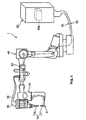
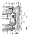
- FIG. 1 is a schematic constructive diagram of the frictional spot joining apparatus 1.
- the frictional spot joining apparatus 1 comprises mainly a joining gun 10 (joining device) and a robot 40 (moving device) to be equipped with the joining gun 10 at or near its arm's tip.
- a conventional six-axis multiple-articulated type of robot may be used as this robot 40.
- the robot 40 is coupled to a control device 50 via a harness 51.
- the joining gun 10 is coupled to the control device 50 via harnesses 52, 54 and 55 and a joint box 53.
- a control unit 50a is disposed in the control device 50, which controls the robot 40 such that the joining gun 10 can take a specific (predetermined or predeterminable) location or orientation and/or position.
- the control unit 50a controls a motor for pressing 14 and a motor for rotating 15 (see FIG. 2 ) that are installed at or on the joining gun 10, which will be described below, such that a joining tool 18 comprising a rotating tool 16 and a receiving tool 17 can perform a specific (predetermined or predeterminable) operation.
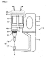
- FIG. 2 is an elevation view of the joining gun 10
- FIG. 3 is a side view of the joining gun 10.
- the joining gun 10 as shown in these figures, comprises an attaching box 11 for attachment to the robot 40, a substantially bent or L-shaped arm 12 that extends e.g. substantially downward from a lower face of the attaching box 11, a body case 13 that is attached to a side face of the attaching box 11 above the arm 12, the pressing motor 14 that is coupled via the harness 54, and the rotating motor 15 that is coupled via the harness 55.
- the rotating tool 16 At or near a lower end of the body case 13 is provided the rotating tool 16, one part of the joining tool 18. Meanwhile, at or near a tip or distal end of the arm 12 is provided the receiving tool 17, the other part of the joining tool 18, which is disposed to substantially face the rotating tool 18 substantially on a rotating axis X of the rotating tool 16.
- the frictional spot joining is executed with the rotating tool 16 and the receiving tool 17 in such a manner that a work to be joined (e.g. a plurality of metal members that at least partly lap over) is located (directly or indirectly) between these tools 16, 17.
- the receiving tool 17 receives the work such that a tip or end portion of the receiving tool 17 substantially contacts one face of the work (if necessary, via a clamping tool), and a tip or end portion of the rotating tool 16 that rotates around the rotational axis X is pressed against the other face of the work, which will be described in detail later.
- the frictional spot joining is or may be executed.
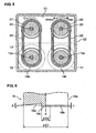
- FIG. 4 is a sectional view showing an inside structure of the body case 13, and FIG. 5 is a sectional view taken along line V-V of FIG. 4 .
- Inside the body case 13 are provided a screw shaft (elevating shaft) 24 and a spline shaft (rotating shaft) 25 that preferably extend substantially vertically in parallel so as to rotate around their axes independently.
- Respective upper ends or end portions of these shafts 24, 25 penetrate an upper lid member 21 and at least partly reach inside an upper cover 22, where driven pulleys 26, 27 are attached to the shafts 24, 25, respectively.
- the upper lid member 21 and upper cover 22 are, as shown in FIG.
- An elevating block 31 is engaged with a screw portion 24a of the screw shaft 24, and a rotating cylinder 35 is engaged with a spline portion 25a of the spline shaft 25.
- the rotating cylinder 35 is provided to rotate at least partly inside the elevating cylinder 33 that is integrally or unitarily coupled to the elevating block 31 via a coupling member 32.
- The-spline shaft 25, elevating cylinder 33 and rotating cylinder 35 are disposed substantially coaxially.
- an integral or unitary body of the elevating block 31, coupling member 32 and elevating cylinder 33 is referred to as an elevating member 30 as a whole.
- a (preferably substantially cylindrical-shaped) substantially downward-projecting portion 13a At the (lower) end face of the body case 13 is formed a (preferably substantially cylindrical-shaped) substantially downward-projecting portion 13a, a lower or distal end of which has a lower cover 23 attached thereto. Respective lower ends of the elevating cylinder 33 and rotating cylinder 35 penetrate the lower cover 23 and project substantially downward. The rotating cylinder 35 located inside projects substantially downward further from the elevating cylinder 33 located outside, and an attaching member 36 is fixed to its lower or distal end. The rotating tool 16 is detachably attached to this attaching member 36. The rotational axis X of the rotating tool 16 attached is substantially coaxial with an axis of the spline shaft 25.
- a bellows 34 preferably is provided between the lower cover 23 and the lower end of the elevating cylinder 33 to protect an outer surface of the elevating cylinder 33 e.g. from any pollution or the like outside the body case 13.
- bearings 25b, 35a and 33a are respectively disposed between the spline shaft 25 and the upper lid member 21, the elevating cylinder 33 and the rotating cylinder 35, and the elevating cylinder 33 and the attaching member 36.
- a servo motor operative to control and/or detect a rotational angle easily be used as the pressing motor 14, and that such a servo motor and/or an induction motor to control easily a rotational speed be used as the rotating motor 15.
- the motors 14, 15 preferably form part of a drive device operative to rotate and/or press the rotating tool 16 against the work.
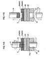
- FIG. 6 is an enlarged view of a tip of the rotating tool 16.
- the tip of the rotating tool 16 comprises a shoulder portion 16b, which is a lower end face (substantially circular-shaped) of a (preferably substantially cylindrical) body portion 16a, that substantially faces the work, a pin 16c that projects from the shoulder portion 16b toward the work by a specified (predetermined or predeterminable) length h having a smaller diameter than the shoulder portion 16b and is located substantially on the rotational axis X of the rotating tool 16, and a (preferably substantially ring-shaped) recess 16d that is provided at least partly around the pin 16c at the shoulder portion 16d.
- the ring-shaped recess 16d preferably is formed substantially in a cone or tronco-cone shape with its center preferably substantially coaxial with the rotational axis X of the rotating tool 16 in such a manner that a bottom face of the ring-shaped recess 16d is inclined with its recess depth outside gradually becomes smaller as shown in the figure.
- the rotating tool 16 has, for example, about 10 mm of a diameter D1 of the shoulder portion 16b, about 2 mm of a diameter D2 of the pin 16c, about 0.3 - 0.35 mm of the projection length h of the pin 16c, and about 5 - 7 degree of an inclined angle ⁇ of the bottom face (or a line tangent thereto) of the ring-shaped recess 16d relative to the shoulder portion 16b.
- a preferred shape of the rotating tool 16 may be determined according to usage factors such as work's material, thickness or the number. Accordingly, it is preferable that a number of different kinds of rotating tools 16 be prepared and the best one be selected among them according to its usage.
- the rotating tool 16 with the ring-shaped recess 16d shown in FIG. 6 is particularly effective in a case where different kinds of metal members having different melting points are joined.
- the pressing motor 14 operates to move the rotating tool 16 in the direction of the rotational axis X of the rotating tool 16 in such a manner that it approaches or goes away from the work located between the both tools 16, 17, which will be described in detail below.
- the pressing motor 14 is configured to press or urge the rotating tool 16 against the work, and herein a pressing force is changeable or controllable preferably according to an electric current supplied to the pressing motor 14.
- the pressing force may be supplied by means of a fluid pressing means (e.g. a hydraulic cylinder).
- a rotational speed of the rotating tool 16 is changeable or controllable preferably according to an electric current supplied to the rotating motor 15 as well.
- FIG. 7 shows a use state of a constructive member of an automotive vehicle body in the frictional spot joining according to the method of a preferred embodiment of the present invention.
- This constructive member of the automotive vehicle body comprises a reinforcement 63 of a trunk lid 60 and a bolt retainer 64 for attaching a hinge 70 (see FIG. 8 ) to the trunk lid 60.
- These members 63, 64 are provided at lateral (right and/or left) corner sides inside the trunk lid 60, which is formed with an outer panel 61 and an inner panel 62 that are attached with their peripheral edges hemmed each other.
- the reinforcement 63 preferably is made of 6000-based aluminum alloy (thickness of about 1.4 mm) and the bolt retainer 64 preferably is made of steel plate (thickness of about 1.0 mm) with an anti-oxidation layer such as a zinc-plating layer.
- the work that may be joined with the frictional spot joining comprises a plurality of metal members (at least a first metal member W1 and a second metal member W2 ).
- the metal members may be made of the same kind of material or different kinds of materials.
- the reinforcement 63 such as aluminum alloy
- the bolt retainer 64 such as zinc-plating steel plate
- the reinforcement 63 is attached to the inner panel 62 at the corner inside the trunk lid 60 via a proper means.
- the bolt retainer 64 is jointed to the reinforcement 63 with the frictional spot joining (with two joining points P ).
- Screw portions of bolts 65, 65 fixed to the bolt retainer 64 preferably by welding or the like project from the inner panel 62 and at least partly penetrate the hinge 70, and are to be fastened to the hinge 70 by nuts 66, 66.
- the frictional spot joining between the reinforcement 63 and the bolt retainer 64 functions as a temporary fixing of the bolt retainer 64 to the trunk lid 60 until the hinge 70 has been attached to the trunk lid 60.
- the one or more joining points P preferably are provided at or near bottom portions 63a, 64a of recesses formed at the reinforcement 63 and the bolt retainer 64.
- These recesses preferably are formed substantially in a circular shape, as apparent from FIG. 7 , in order to increase the rigidity of the reinforcement 63 and/or form a space to remove waste R (see FIG. 15 ) that may be generated during the joining.
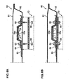
- FIG. 9 shows a process of the frictional spot joining with the reinforcement 63 and the bolt retainer 64 of the work being fixed by a clamping tool 80 (specifically, a first clamping tool 81 through a sixth clamping tool 86 ) of the frictional spot joining apparatus 1. Namely, it shows a state the joining of the first joining point P (on the left side) is done, which is right before the start of the joining of the second joining point P (on the right side).
- rotating tool 16 is set to be located substantially above and the receiving tool 17 is set to be located below in FIG. 9 , these tools may be set in any other orientation such as at reverse positions respectively.
- a bottom portion 63a of the reinforcement 63 and a bottom portion 64a of the bolt retainer 64 are set with a small gap S (preferably about 0.3 - 0.6 mm). This is to provide a certain gap around the joining point P after the joining, which allows an easier flowing-in of a coating material preferably in an electrodeposition coating process (detailed description is omitted).
- the both members can be set substantially without any gap between the both bottom portions 63a, 64a.
- the clamping tool 80 to fix or locate the reinforcement 63 and the bolt retainer 64 in specified (predetermined or predeterminable) positions comprises a first clamping tool 81, a second clamping tool 82 and a third clamping tool 83, which are located on a side of the bolt retainer 64, and a fourth clamping tool 84, a fifth clamping tool 85 and a sixth clamping tool 86, which are located on a side of the reinforcement 63.
- the second clamping tool 82 on the side of the bolt retainer 64 supports a base portion 64b of the bolt retainer 64.
- the third clamping tool 83 supports the bottom portion 64a of the bolt retainer 64.
- the first clamping tool 81 is located preferably in a lowermost position and supports the second and third clamping tools 82, 83 together.
- the fourth clamping tool 84 on the side of the reinforcement 63 supports a base portion 63b of the reinforcement 63.
- One or more bolt holes 84a are formed at the base portion 63b, and the one or more screw portions of the respective bolts 65 are at least partly inserted into these bolt holes 84a.
- the fifth clamping tool 85 which supports the bottom portion 63a of the reinforcement 63, specifically supports an intermediate portion between the two joining points P at the bottom portion 63a. This support is to preferably prevent the intermediate portion between the two joining points P from rising away from the bottom portion 64a.
- the sixth clamping tool 86 preferably is located in an uppermost position and supports the fourth and fifth clamping tools 84, 85 together.
- the holding member 90 is a member that restrains the runout of the receiving tool 17 (a movement in a direction at an angle different from 0° or 180°, preferably substantially perpendicular to the rotational axis X of the rotating tool 16 ) at the joining, not a member to fix the work.
- the holding member 90 includes one or more through holes 92 (restriction portions) at locations that substantially correspond to the one or more joining points P, respectively.
- Each through hole 92 has a diameter that is nearly an outer diameter of the receiving tool 17 (for example, (the outer diameter of the receiving tool 17 ) + 0.2 mm) so that the receiving tool can be allowed to at least partly go therein.
- clamping tool 80 and holding tool 90 are fixed firmly with a clamping mechanism having a hydraulic cylinder or the like, fixing bolts and so on (not illustrated here).
- FIG. 10 is a perspective view of the fifth clamping tool 85, when viewed from below.
- the first, second, third, fourth and sixth clamping tools 81, 82, 83, 84 and 86 preferably are of a substantially flat-plate shape, but the fifth clamping tool 85 preferably has a rather complicated shape since it is located to support in a narrow space.
- the fifth clamping tool 85 has a three-story or three-level structure, having a base portion 85a located in the uppermost position, a middle or intermediate portion 85b and a top end portion 85c located in the lowermost position.
- the base portion 85a in a substantially flat-plate shape has one or more (e.g. four) bolt holes 85e at corners.
- the fifth clamping tool 85 and the sixth clamping tool 86 are fixed together by one or more bolts, not illustrated, which are at least partly inserted into these bolt holes 85e.
- the middle or intermediate portion 85b preferably is of a substantially circular-plate shape, which seems like a shape that could be made by raising part of the base portion 85a except part of the bolt holes 85e. It has a hole or recess portion 85d that allows the base portion 85a and the middle portion 85b to at least partly go therein.
- the hole portion 85d preferably substantially has an oval cross section that encompasses the two joining points P and would not interfere with the rotating tool 16 located in any positions at the joining points P (a state of the rotating tool 16 located in the position at one joining point P is illustrated by a two-dotted broken line in the figure).
- the top end portion 85c is a member that is formed to project from the middle portion 85b .
- a tip of the portion 85c presses directly the intermediate portion between the joining points P of the bottom portion 63a of the reinforcement 63, and thereby the intermediate portion preferably can be prevented from rising (projecting) at the joining.
- the top end portion 85c is configured to at least partly cross the oval hole portion 85d like between straight-line portions of the hole portion 85d, so that it would not interfere with the rotating tool 16 located in any positions at the joining points P.
- the fifth clamping tool 85 can support the relatively narrow intermediate portion between the joining points P properly, without badly influencing on the movement of the rotating tool 16 at the joining.
- the rotating tool 16 is let go down into the hole portion 85d without substantially interfering with the top end portion 85c. Namely, it is let go down through a narrow space between the middle portion 85b and the top end portion 85c.
- the joining gun 10 is moved by the robot 40 so as to approach the joining point P, where the rotating tool 16 preferably is located on the side of the reinforcement 63 and the receiving tool 17 preferably is located on the side of the bolt retainer 64. Subsequently, the joining gun 10 is moved to the side of the bolt retainer 64, namely, such that the receiving tool 17 approaches the bolt retainer 64.
- the receiving tool 17 approaches the side of the bolt retainer 64 and then at least partly goes into the through hole 92, and eventually its tip 17a substantially contacts the lower face of the clamping tool 80 (specifically, the first clamping tool 81 ) and stops there. Then, in this state, the rotating tool 16 is rotated and moved toward the reinforcement 63 by the pressing motor 14 and rotating motor 15, and pressed to execute the frictional spot joining as shown in FIG. 11A .
- Process of this joining preferably comprises at least part of the following steps: an initial moving step, first pressing step, second pressing step, and third pressing step. Hereinafter, these steps will be described in detail.
- the rotating tool 16 In the initial moving step, the rotating tool 16 is moved to go down to or to be positioned at an initial position close to the reinforcement 63, where the tip of the pin 16c of the rotating tool 16 preferably is very close to the reinforcement 63, not contacting it.
- the rotating tool 16 may be or not under rotation in the initial moving step, it is under rotation preferably with the substantially same rotational speed as that in the subsequent first pressing step (with a first rotational speed) in the present embodiment, so that the rotating tool 16 can smoothly change its state to the first pressing step.
- the rotating tool 16 under rotation with the first rotational speed is pressed down or urged against the reinforcement 63 by the pressing motor 14 preferably with a first pressing force that is greater than a moving resistance of the rotating tool 16 in the initial moving step in such a manner that the shoulder portion 16b and pin 16c substantially contact the reinforcement 63 for a first specified (predetermined or predeterminable) period.
- a right-half part illustrates a state where there is provided the gap S between the reinforcement 63 and the bolt retainer 64
- a left-half part illustrates a state where no gap S is provided and the both contact each other.
- the above-described control unit 50a controls preferably the electric current supplied to the pressing motor 14 such that the pressing force can be the above-described first (predetermined or predeterminable) pressing force for the above-described specified (predetermined or predeterminable) period in the first pressing step.
- the control unit 50a controls the electric current supplied to the rotating motor 15 such that the rotational speed can be the above-described (predetermined or predeterminable) first rotational speed in the first pressing step (and the initial moving step).
- the above-described moving resistance which may be determined by a frictional resistance in a mechanism for moving the elevating cylinder 33 (rotating tool 16 ) that is comprised of the screw shaft 24, elevating member 30 and so on, is not stable, changeable according to the amount of gap or grease or lubrication between a moving portion and a fixed portion. Accordingly, if the first pressing force is less than the moving resistance, the time period before the first pressing force acts on the reinforcement 63 actually would be changeable according to the magnitude of the moving resistance, and therefore an actual time of pressing with the first pressing force would become unstable within the first specified period.
- the shoulder portion 16b and the pin 16c of the rotating tool 16 can be pressed against the reinforcement 63 with the first pressing force right after the starting of the first pressing step, regardless of the magnitude of moving resistance.
- the time period of the first pressing force acting on the reinforcement 63 can become substantially the same as the first specified time and therefore stable.
- the first pressing force be set to be substantially greater than a maximum magnitude of the moving resistance that preferably may change within a changing range (more preferably between about 2.45 and 3.43 kN). Also, it is preferable that the first rotational speed be set to be between about 1500 and about 3500 rpm, and/or that the first specified time be set to be between about 0.2 and about 2.0 sec.
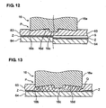
- the first pressing force, first rotational speed and first specified time are respectively set so properly that the rotating tool 16 can be pressed against the reinforcement 63 in such a manner that part of the bottom face of the ring-shaped recess 16d (a deep portion near the rotational axis X ) does not contact the reinforcement 63 but a peripheral edge portion of the shoulder 16b and the pin 16c substantially contact the reinforcement 63.
- the pressing of the peripheral edge portion of the shoulder portion 16b and the pin 16c under rotation around the axis X against the reinforcement 63 generate a frictional heat preferably at two contact points or areas.
- the frictional heat diffuses to part of the work between these two contact points or areas (a portion where the bottom face of the ring-shaped recess 16d does not contact) and then to a substantially entire part of the joining spot P, and thereby a substantially entire part of the reinforcement 63 that the shoulder portion 16b substantially faces (i.e., joining point P ) is softened properly.
- the zinc-plating layer Z formed on the surface of the bolt retainer 64 is softened at the joining point P. Accordingly, by properly setting the first pressing force, first rotational speed and/or first specified (predetermined or predeterminable) time, the reinforcement 63 can be softened effectively without occurring a shearing breakage.
- the pin 16c projecting by the length h from the shoulder portion 16b contacts the reinforcement 63 preferably in advance, prior to the shoulder portion 16b.
- This advanced contact of the narrow pin 16c can provide a proper centering of the rotating tool 16 with a smaller frictional resistance, thereby restraining the rotational runout in the-direction substantially perpendicular to the rotational axis X of the tool 16 (anchor function).
- the rotating tool 16 is rotated by the rotating motor 15 at the second rotational speed (preferably different from the first rotational speed) and the shoulder portion 16b and the pin 16c are pressed by the pressing motor 14 against the reinforcement 63 with the second pressing force preferably greater than the first pressing force for the second specified (predetermined or predeterminable) time.
- the shoulder portion 16b and the pin 16c go into the reinforcement 63 deeply, so that the substantially entire bottom face of the ring-shaped recess 16d, namely the substantially entire shoulder portion 16b including the pin and the recess 16d contacts the reinforcement 63.
- the plastic flow Q is schematically illustrated by broken lines in the figure 13 ).
- the reinforcement 63 is pushed toward the bolt retainer 64 by the plastic flow Q and the both contact each other closely.
- the reinforcement 63 in the plastic flow tends to move vertically in the figure, thereby preventing effectively its flowing out from a portion (joining point P ) that is located just below the rotating tool 16. Also, the second pressing force is focused on the joining point P by the ring-shaped recess 16d, thereby promoting the plastic flow Q of the reinforcement 63.
- part of the zinc-plating layer Z that has been softened or melt is substantially pushed out from the joining point P, so that a new uncovered surface of the bolt retainer 64 is exposed.
- an oxidation film, not illustrated, which has been formed on the surface of the reinforcement 63 due to oxygen in the air, is destroyed at the joining point P, so that a new uncovered surface of the reinforcement 63 is exposed.
- the second pressing force be set to be between about 3.92 and about 5.88 kN.
- the second rotational speed be set to be between about 2000 and about 3000 rpm, and/or that the second specified (predetermined or predeterminable) time be set to be between about 1.0 and about 2.0 sec.
- the second pressing force, second rotational speed and second specified time are respectively set so properly that the rotating tool 16 preferably does not go into reinforcement 63 more deeply from a specified (predetermined or predeterminable) position. This specified (predetermined or predeterminable) position is such that if the rotating tool 16 goes into further deeply, the reinforcement 63 may become too thin and be torn away.
- this rotation runout of the rotating tool 16 is effectively restrained by the holding member 90 and the one or more through holes 92 (restriction portion) as described below.
- the rotating tool 16 and the drive device are provided at the joining gun 10 (joining device) as shown in FIG. 2 . Accordingly, if the rotational runout of the rotating tool 16 occurs, the joining gun 10 also vibrate as a whole. This vibration is transmitted to the receiving tool 17 through the bent or L-shaped arm 12. Thus, unless there is provided any means to restrain the movement of the receiving tool 17, the runout of the receiving tool 17 (vibration in direction at an angle different from 0° or 180°, preferably substantially perpendicular to the rotational axis X ) is caused by the rotating tool 16 having the rotational runout.
- the receiving tool 17 is at least partly put into the through hole 92 of the holding member 90 as shown in FIG. 11A and thereby its runout is restrained. And, the vibration of the joining gun 10 is restrained by a reaction function of this restraint, and accordingly the rotational runout of the rotating tool 16 is also restrained. The adhesion of the work to the shoulder portion 16b is properly prevented by this restraint of the rotational runout. Thus, promotion of the rotational runout, decrease of joining quality, any damage of the rotating tool 16, its drive mechanism or the clamping tool 80 can be avoided properly.
- the runout restraint of the receiving tool 17 is achieved with a very simple structure of the through hole 92 formed at the (preferably substantially flat-plate-shaped) holding member 90. Accordingly, comparing with the conventional restraint structure of the rotating tool 16 using springs, bearings and so on, smaller size and low costs of the device can be further achieved. Also, this is particularly advantageous for the rotating tool 16 that needs to at least partly go through a narrow space between the middle or intermediate portion 85b and the top end portion 85c of the fifth clamping tool 85 to have access to the joining point P. Further, this should be advantageous when the receiving tool 17 is arranged to go through a narrow space as well.
- the second pressing step preferably is complete in the state where the rotational runout is effectively restrained accordingly.
- the joining at the joining point P may be finished with the completion of the second pressing step, the present embodiment preferably has additional third pressing step.
- the rotating tool 16 is rotated by the rotating motor 15 at the third rotational speed and the shoulder portion 16b and the pin 16c are pressed by the pressing motor 14 against the reinforcement 63 with the third pressing force preferably smaller than the second pressing force for the third specified (predetermined or predeterminable) time.
- the rotating tool 16 since the pressing force preferably is smaller than the second pressing force, the rotating tool 16 would not go into deeper from the above-described specified position and keep remained at the position when the second pressing step is complete. Thus, it is avoided that the reinforcement 63 would become too thin and be torn away. And, the temperature that preferably is substantially the same as that in the second pressing step is maintained and thereby a proper plastic flow is provided for a long period.
- this third pressing step is complete, the joining at the joining spot P is finished.
- the third pressing force be set to be lower than the first pressing force (more preferably between about 0.49 and about 1.47 kN). Also, it is preferable that the third rotational speed be set to be between about 1500 and about 3500 rpm, and/or that the third specified (predetermined or predeterminable) time be set to be between about 0.5 and about 2.5 sec.
- the third pressing force, third rotational speed and third specified time are respectively set so properly that the rotating tool 16 pressed against the reinforcement 63 can be kept in the position at the completion of the second pressing step and the plastic flow of the reinforcement can occur.
- a metal material pushed out by the rotating tool 16 rises out on the surface of the reinforcement 63 as the waste R and/or the zinc-plating layer Z is further pushed substantially out from the joining point P.
- the oxidation film preferably is further destroyed and thereby the exposure range of the new uncovered surfaces of the reinforcement 63 and bolt retainer 64 is enlarged (the range shown with x marks in FIG. 14 ). As a result, the both surfaces are joined together firmly in the solded state, so that the joining strength becomes stably high.
- a metal-mixed layer Y that is comprised of the metal (aluminum alloy) of the reinforcement 63 and the metal of the zinc-plating layer Z is formed.
- the joining gun 10 When the jointing at the joining spot P is complete, the joining gun 10 is moved to a standby position by the robot 40 controlled by the control unit 50a. In a case where the joining is executed to another joining spot P subsequently, the gun 10 is moved to that position and the joining process described above is repeated.
- a holding member 90 is provided on a side of the receiving tool 17, which has a restriction portion 92 to restrain a movement of the receiving tool 17 in a direction at an angle different from 0° or 180°, preferably substantially perpendicular to the rotational axis X, and the joining device is moved by a moving device 40 such that the receiving tool 17 is disposed at the restriction portion 92. Accordingly, the rotational runout of the rotating tool 16 can be restrained effectively with a simple structure of a properly small-sized rotating tool and receiving tool.
- the joining can be applied to other members.
- the material of those members should not be limited. The same material or different materials can be similarly applied.
- the number of members to be joined should not be limited to the two. Three members or more can be also applied.
- the shoulder portion 16b of the rotating tool 16 does not necessarily have the ring-shaped recess 16d. Instead, the shoulder portion 16 having a substantially flat face may be used.
- the restriction portion to restrain the runout of the receiving tool 17 comprises the through hole 92 formed at the holding member 90 in the above-described embodiment
- another structure may be applied.
- a plurality of slender cylinders may be provided so as to at least partly surround the side face of the receiving member 17 and restrain the runout of the receiving member 17.
- the receiving tool 17 may be provided at the joining gun 10 so as to move substantially vertically and it is moved to the restriction portion (through hole 92 ) by the drive device.
- the fixed disposition of the receiving tool 17 to the joining gun 10 may be better in terms of the effective restraint of the rotational runout of the rotating tool 16.
- the receiving tool 17 of the above-described embodiment is configured such that its tip 17a contacts the work via the clamping tool 80 that comprises two members (first clamping tool 81 and third clamping tool 82 ).
- the clamping tool 80 may comprise one member or three members or more.
- the receiving tool 17 may be configured such that its tip 17a contacts the work direction without any clamping tool.
- the above-described embodiment of the receiving tool 17 with the tip 17a contacting the work via the clamping tool can avoid any problems that would be caused by the constitution of the receiving tool 17 with the tip 17a directly contacting the work.
- the softened or melt zinc-plating layer Z of the bolt retainer 64 adheres to the receiving tool 17 by the heat and pressing force at the joining. Also, in a case where the face of the work that the receiving tool 17 contacts constitutes an outer surface of a vehicle panel, a pressing spot mark that may be formed by the contact of the receiving tool 17 would deteriorate the quality of a product of the vehicle.
- the holding member 90 may be formed integrally or unitarily to the clamping member 80.
- the first clamping tool 81 and the holding member 90 may be formed integrally or unitarily.
- the flexibility would be more superior. Because even if the location of the joining point P needs to be changed according to a design changing or a production with different kinds, this requirement may be met by exchanging and selecting a proper holding member having a suitable location of the through hole 92.
- the rotating tool 16 or the joining gun 10 need not to be provided at the robot 40, and it may be provided at an automatic machine that can move in a direction of three axes, X, Y and Z axes.
- the layout that these tools 16, 17 are provided at the robot 40 may provide a superior joining with a high moving flexibility where the joining can be executed properly even in a relatively narrow area.
- the shape (dimensions of portions) of the rotating tool 16, the gap between the receiving tool 17 and the through hole 92, or various parameters such as the pressing force may be properly determined according to usage or various conditions thereof.
Claims (10)
- Reibrührpunktschweißverfahren, in dem eine Vielzahl von Metallgliedern (63, 64), die zumindest teilweise überlappen, mit einer Verbindungsvorrichtung (10) verbunden wird, die hat: ein rotierendes Werkzeug (16), ein aufnehmendes Werkzeug (17), das derart angeordnet ist, dass es im Wesentlichen auf einer Rotationsachse (X) des rotierenden Werkzeugs (16) dem rotierenden Werkzeug (16) im Wesentlichen zugewandt ist, und eine Antriebsvorrichtung (14, 15), die betriebsfähig ist, um das rotierende Werkzeug (16) in einer Schubrichtung in Richtung der Metallglieder (63, 64) zu drehen und zu bewegen, wobei die zumindest teilweise überlappenden Metallglieder (63, 64), wenn sie verbunden werden, zwischen dem rotierenden Werkzeug (16) und dem aufnehmenden Werkzeug (17) der Verbindungsvorrichtung (10) angeordnet sind, wobei das rotierende Werkzeug (16) derart aufgebaut ist, dass es gegen eines der Metallglieder (63, 64) gedrückt werden soll, so dass zumindest das eine der Metallglieder (63, 64) durch von dem rotierenden Werkzeug (16) erzeugte Reibungswärme erweicht wird und in einen plastischen Fließzustand gebracht wird, wobei das Verfahren umfasst:einen Schritt zum Bereitstellen eines Halteelements (90),dadurch gekennzeichnet, dass das Halteelement (90) neben dem aufnehmenden Werkzeug (17) angeordnet ist, wenn die Metallglieder (63, 64) verbunden werden, und das Halteelement (90) ferner neben oder angrenzend an die Metallglieder (63, 64) vorgesehen ist,das Halteelement (90) einen einschränkenden Abschnitt bzw. Behälter (92) hat, der betriebsfähig ist, um eine Bewegung des aufnehmenden Werkzeugs (17) in einer Richtung zu beschränken, die in einem anderen Winkel als 0° oder 180°, bevorzugt im Wesentlichen senkrecht zu der Rotationsachse (X) des rotierenden Werkzeugs (16), angeordnet ist; unddas Reibrührpunktschweißverfahren ferner einen Schritt zum Bewegen der Verbindungsvorrichtung (10) durch eine Bewegungsvorrichtung (40) umfasst, so dass das aufnehmende Werkzeug (17) an dem einschränkenden Abschnitt (92) des Halteelements (90) angeordnet ist, wobei die Bewegung des aufnehmenden Werkzeugs (17) durch den einschränkenden Abschnitt (92) des Haltelements (90) beschränkt wird, wenn die Metallglieder (63, 64) verbunden werden.
- Reibrührpunktschweißverfahren nach Anspruch 1, wobei die Metallglieder (63, 64) ein erstes Metallglied (W1) und ein zweites Metallglied (W2) umfassen, wobei ein Schmelzpunkt des zweiten Metallglieds (W2) höher als der des ersten Metallglieds (W1) ist, und das rotierende Werkzeug (16) derart aufgebaut ist, dass es gegen das erste Metallglied (W1) gedrückt wird, so dass das rotierende Werkzeug (16) zumindest teilweise in das erste Metallglied (W1) geht, wobei es das zweite Metallglied (W2) im Wesentlichen nicht erreicht, wobei nur das erste Metallglied (W1) durch die von dem rotierenden Werkzeug (16) erzeugte Reibungswärme erweicht und in den plastischen Fließzustand gebracht werden kann und die Punktflächen der ersten und zweiten Metallglieder (W1, W2) in einem festen Zustand verbunden werden..
- Reibrührpunktschweißverfahren nach einem der vorangehenden Ansprüche, wobei das rotierende Werkzeug (16) einen Absatzabschnitt (16b) umfasst, der an dessen Spitze mit einer ringförmigen Vertiefung (16d) ausgebildet ist, und einen Stift (16c), der von dem Absatzabschnitt (16b) vorsteht, um im Wesentlichen auf der Rotationsachse (X) des rotierenden Werkzeugs (16) angeordnet zu sein.
- Reibrührpunktschweißverfahren nach einem der vorangehenden Ansprüche, wobei das Verbinden durchgeführt wird bei einer ersten Press- bzw. Druckkraft für eine erste spezifizierte Zeitspanne, um das rotierende Werkzeug (16) an eine spezifizierte Position zu bringen, und dann bei einer zweiten Druckkraft für eine zweite spezifizierte Zeitspanne, wobei die zweite Druckkraft höher als die erste Druckkraft ist.
- Reibrührpunktschweißvorrichtung (1), in der eine Vielzahl von Metallgliedern (63, 64), die zumindest teilweise überlappen, mit einer Verbindungsvorrichtung (10) verbunden ist, die hat: ein rotierendes Werkzeug (16), ein aufnehmendes Werkzeug (17), das derart angeordnet ist, dass es im Wesentlichen auf einer Rotationsachse (X) des rotierenden Werkzeugs (16) dem rotierenden Werkzeug (16) im Wesentlichen zugewandt ist, und eine Antriebsvorrichtung (14, 15), die betriebsfähig ist, um das rotierende Werkzeug (16) in einer Schubrichtung in Richtung der Metallglieder (63, 64) zu drehen und zu bewegen, wobei die zumindest teilweise überlappenden Metallglieder (63, 64), wenn sie verbunden werden, zwischen dem rotierenden Werkzeug (16) und dem aufnehmenden Werkzeug (17) der Verbindungsvorrichtung (10) angeordnet sind, wobei das rotierende Werkzeug (16) derart aufgebaut ist, dass es gegen eines der Metallglieder (63, 64) gedrückt werden soll, so dass zumindest das eine der Metallglieder (63, 64) durch von dem rotierenden Werkzeug (16) erzeugte Reibungswärme erweicht wird und in einen plastischen Fließzustand gebracht wird, wobei die Vorrichtung umfasst:ein Halteelement (90),dadurch gekennzeichnet, dass das Halteelement (90) auf einer Seite des aufnehmenden Werkzeugs (17) angeordnet ist, wenn die Metallglieder (63, 64) verbunden werden,das Halteelement (90) einen einschränkenden Abschnitt (92) hat, der betriebsfähig ist, um eine Bewegung des aufnehmenden Werkzeugs (17) in einer Richtungt zu beschränken, die in einem anderen Winkel als 0° oder 180°, bevorzug im Wesentlichen senkrecht zu der Rotationsachse (X) des rotierenden Werkzeugs (16), angeordnet ist; unddie Reibrührpunktschweißvorrichtung ferner eine Bewegungsvorrichtung (40) umfasst, die betriebsfähig ist, um die Verbindungsvorrichtung (10) zu bewegen, so dass das aufnehmende Werkzeug (17) an dem einschränkenden Abschnitt (92) des Halteelements (90) angeordnet ist, wobei die Bewegung des aufnehmenden Werkzeugs (17) durch den einschränkenden Abschnitt (92) des Haltelements (90) beschränkt werden kann, wenn die Metallglieder (63, 64) verbunden werden.
- Reibrührpunktschweißvorrichtung (1) nach Anspruch 5, wobei die Metallglieder (63, 64) ein erstes Metallglied (W1) und ein zweites Metallglied (W2) umfassen, wobei ein Schmelzpunkt des zweiten Metallglieds (W2) höher als der des ersten Metallglieds (W1) ist, und das rotierende Werkzeug (16) derart aufgebaut ist, dass es gegen das erste Metallglied (W1) gedrückt wird, so dass das rotierende Werkzeug (16) zumindest teilweise in das erste Metallglied (W1) geht, wobei es das zweite Metallglied (W2) im Wesentlichen nicht erreicht, wobei nur das erste Metallglied (W1) durch die von dem rotierenden Werkzeug (16) erzeugte Reibungswärme erweicht und in den plastischen Fließzustand gebracht werden kann und die Punktflächen der ersten und zweiten Metallglieder (W1, W2) in einem festen Zustand verbunden werden.
- Reibrührpunktschweißvorrichtung (1) nach Anspruch 5 oder 6, wobei das rotierende Werkzeug (16) einen Absatzabschnitt (16b) umfasst, der an dessen Spitze mit einer ringförmigen Vertiefung (16d) ausgebildet ist, und einen Stift (16c), der von dem Absatzabschnitt (16b) vorsteht, um im Wesentlichen auf der Rotationsachse (X) des rotierenden Werkzeugs (16) angeordnet zu sein.
- Reibrührpunktschweißvorrichtung (1) nach Anspruch 5, 6 oder 7, wobei der einschränkende Abschnitt ein Durchgangsloch (92) umfasst, das an dem Haltelement (90) ausgebildet ist, wobei das Durchgangsloch (92) eine Form hat, die dem aufnehmenden Werkzeug (17) erlaubt, in es hinein zu gehen, wenn die Metallglieder (63, 64) verbunden werden.
- Reibrührpunktschweißvorrichtung (1) nach einem der Ansprüche 5 bis 8, die ein Klemmwerkzeug (80) umfasst, um die zumindest teilweise überlappenden Metallglieder (63, 64) in einer Verbindungsposition zu befestigen, wobei das Halteelement (90) an dem Klemmwerkzeug (80) befestigt ist, das eine Fläche des Verbindungsbereichs der Metallglieder (63, 64) berührt, und wobei eine Spitze (17a) des aufnehmenden Werkzeugs (17) die Metallglieder (63, 64) über das Klemmwerkzeug (80) hält.
- Reibrührpunktschweißvorrichtung (1) nach einem der Ansprüche 5 bis 9, wobei die Bewegungsvorrichtung einen Roboter (40) umfasst.
Applications Claiming Priority (1)
| Application Number | Priority Date | Filing Date | Title |
|---|---|---|---|
| JP2005283707A JP4586698B2 (ja) | 2005-09-29 | 2005-09-29 | 摩擦点接合装置 |
Publications (2)
| Publication Number | Publication Date |
|---|---|
| EP1769876A1 EP1769876A1 (de) | 2007-04-04 |
| EP1769876B1 true EP1769876B1 (de) | 2008-08-27 |
Family
ID=37492440
Family Applications (1)
| Application Number | Title | Priority Date | Filing Date |
|---|---|---|---|
| EP06019390A Expired - Fee Related EP1769876B1 (de) | 2005-09-29 | 2006-09-15 | Reibrührpunktschweissverfahren und -vorrichtung mit einem einen einschränkenden Teil aufweisenden Behalter |
Country Status (5)
| Country | Link |
|---|---|
| US (1) | US7703655B2 (de) |
| EP (1) | EP1769876B1 (de) |
| JP (1) | JP4586698B2 (de) |
| CN (1) | CN1939635B (de) |
| DE (1) | DE602006002461D1 (de) |
Families Citing this family (15)
| Publication number | Priority date | Publication date | Assignee | Title |
|---|---|---|---|---|
| JP4134837B2 (ja) * | 2003-07-15 | 2008-08-20 | マツダ株式会社 | 摩擦接合方法および摩擦接合構造 |
| US20070039154A1 (en) * | 2005-08-02 | 2007-02-22 | Mazda Motor Corporation | Frictional spot joining method and frictional spot joining apparatus |
| JP4968447B2 (ja) * | 2006-12-25 | 2012-07-04 | マツダ株式会社 | 金属構成部材の接合方法及びその接合構造 |
| JP2009137387A (ja) * | 2007-12-05 | 2009-06-25 | Koito Mfg Co Ltd | 取付構造及び溶着方法 |
| JP5521241B2 (ja) * | 2010-09-03 | 2014-06-11 | 三菱日立製鉄機械株式会社 | 摩擦攪拌接合システムおよび摩擦攪拌接合方法 |
| EP2844415B1 (de) * | 2012-04-30 | 2016-08-03 | Université Catholique de Louvain | Verfahren zum verschweissen von mindestens zwei schichten |
| CN103801816A (zh) * | 2012-11-07 | 2014-05-21 | 上海航天设备制造总厂 | 搅拌摩擦点焊机器人装置和利用该装置焊接的方法 |
| CN103801815A (zh) * | 2012-11-07 | 2014-05-21 | 上海航天设备制造总厂 | 一种功率超声辅助搅拌摩擦点焊装置及焊接方法 |
| US20170008121A1 (en) * | 2015-07-06 | 2017-01-12 | GM Global Technology Operations LLC | Enhanced friction-stir-welding joint strength between steel and aluminum with surface coating and preformed local texture |
| DE102015217460A1 (de) * | 2015-09-11 | 2017-03-16 | Volkswagen Aktiengesellschaft | Verfahren zum Fügen eines Stahl aufweisenden Bauteils mit einem Aluminium aufweisenden Bauteil |
| EP3653329B1 (de) * | 2017-09-13 | 2023-10-11 | JFE Steel Corporation | Verfahren zum beidseitigen reibrührschweissen von metallplatten |
| WO2020017094A1 (ja) * | 2018-07-19 | 2020-01-23 | 日本軽金属株式会社 | 液冷ジャケットの製造方法 |
| CN109290711B (zh) * | 2018-11-29 | 2023-09-12 | 广东工业大学 | 门铰链与门板的焊接方法及焊接设备 |
| CN111014940B (zh) * | 2019-12-27 | 2021-12-24 | 中国航空制造技术研究院 | 一种机器人搅拌摩擦点焊镜像焊接方法 |
| CN111014939B (zh) * | 2019-12-27 | 2021-12-24 | 中国航空制造技术研究院 | 一种机器人搅拌摩擦点焊镜像焊接方法 |
Family Cites Families (16)
| Publication number | Priority date | Publication date | Assignee | Title |
|---|---|---|---|---|
| US5611479A (en) * | 1996-02-20 | 1997-03-18 | Rockwell International Corporation | Friction stir welding total penetration technique |
| JP3070735B2 (ja) * | 1997-07-23 | 2000-07-31 | 株式会社日立製作所 | 摩擦攪拌接合方法 |
| NL1011908C1 (nl) * | 1999-04-27 | 2000-10-30 | Fokker Aerostructures Bv | Wrijvingsroerlassen. |
| JP3867475B2 (ja) * | 2000-04-28 | 2007-01-10 | マツダ株式会社 | 金属部材の処理方法 |
| EP1345729B1 (de) | 2000-05-08 | 2008-07-09 | Brigham Young University | Drehendes rohrschweissen mittels eines superabrasiven werkzeuges |
| EP1372899B1 (de) * | 2001-03-29 | 2005-10-26 | Mazda Motor Corporation | Drehendes reibungschweissverfahren und vorrichtung |
| JP3471338B2 (ja) * | 2001-07-30 | 2003-12-02 | 川崎重工業株式会社 | 摩擦攪拌接合装置 |
| JP2004141898A (ja) * | 2002-10-23 | 2004-05-20 | Hitachi Ltd | 摩擦攪拌接合方法および装置 |
| JP3864888B2 (ja) * | 2002-10-28 | 2007-01-10 | マツダ株式会社 | 摩擦撹拌を用いた接合方法 |
| JP3859582B2 (ja) | 2002-11-18 | 2006-12-20 | 川崎重工業株式会社 | 摩擦撹拌接合装置および摩擦撹拌接合方法 |
| JP3911232B2 (ja) * | 2002-11-18 | 2007-05-09 | 川崎重工業株式会社 | 摩擦撹拌接合装置 |
| JP4134837B2 (ja) * | 2003-07-15 | 2008-08-20 | マツダ株式会社 | 摩擦接合方法および摩擦接合構造 |
| JP4542795B2 (ja) * | 2004-02-05 | 2010-09-15 | 本田技研工業株式会社 | 摩擦撹拌接合方法及びその治具 |
| US20050092809A1 (en) * | 2003-10-29 | 2005-05-05 | Mazda Motor Corporation | Friction agitation welding apparatus |
| JP4516410B2 (ja) * | 2004-11-10 | 2010-08-04 | 本田技研工業株式会社 | 積層体の接合方法 |
| JP4729921B2 (ja) * | 2004-12-24 | 2011-07-20 | マツダ株式会社 | 摩擦点接合方法およびその装置 |
-
2005
- 2005-09-29 JP JP2005283707A patent/JP4586698B2/ja not_active Expired - Fee Related
-
2006
- 2006-08-21 US US11/506,780 patent/US7703655B2/en not_active Expired - Fee Related
- 2006-09-15 DE DE602006002461T patent/DE602006002461D1/de active Active
- 2006-09-15 EP EP06019390A patent/EP1769876B1/de not_active Expired - Fee Related
- 2006-09-27 CN CN2006101423013A patent/CN1939635B/zh not_active Expired - Fee Related
Also Published As
| Publication number | Publication date |
|---|---|
| DE602006002461D1 (de) | 2008-10-09 |
| CN1939635A (zh) | 2007-04-04 |
| JP2007090393A (ja) | 2007-04-12 |
| JP4586698B2 (ja) | 2010-11-24 |
| US20070068993A1 (en) | 2007-03-29 |
| EP1769876A1 (de) | 2007-04-04 |
| CN1939635B (zh) | 2010-05-12 |
| US7703655B2 (en) | 2010-04-27 |
Similar Documents
| Publication | Publication Date | Title |
|---|---|---|
| EP1769876B1 (de) | Reibrührpunktschweissverfahren und -vorrichtung mit einem einen einschränkenden Teil aufweisenden Behalter | |
| US6726084B2 (en) | Friction stir heating/welding with pin tool having rough distal region | |
| EP1189723B1 (de) | Verfahren zum behandeln metallischer werkstoffe | |
| US8167188B2 (en) | Friction stir welding method | |
| JP3726786B2 (ja) | 接合方法及び接合ツール | |
| JP3400409B2 (ja) | 接合方法及び接合装置 | |
| US11806801B2 (en) | Joining method | |
| WO2004037478A1 (en) | Method and device for friction agitation welding | |
| JP2005161382A (ja) | 金属部材のスポット接合方法およびその装置。 | |
| JP2005034879A (ja) | 摩擦接合方法および摩擦接合構造 | |
| KR101799218B1 (ko) | 마찰 교반 접합 방법 | |
| JP4729921B2 (ja) | 摩擦点接合方法およびその装置 | |
| JP2002066760A (ja) | 金属の接合方法及び接合装置 | |
| JP4853184B2 (ja) | 摩擦点接合装置 | |
| JP3398135B2 (ja) | スポット接合装置、付加材料、付加材料供給装置およびスポット接合方法 | |
| JP4940246B2 (ja) | 摩擦攪拌点溶接装置 | |
| JP2002096182A (ja) | 摩擦熱に基づく接合方法、回転ツール及び接合体 | |
| JP6794945B2 (ja) | 接合方法 | |
| JP4661367B2 (ja) | 摩擦点接合方法及びその装置 | |
| JP4496942B2 (ja) | 摩擦点接合方法 | |
| JP2002066762A (ja) | 部材の接合方法及び接合装置 | |
| JP2004298902A (ja) | 摩擦攪拌接合方法及び装置 | |
| JP2002066766A (ja) | 部材の接合方法 | |
| JP2009208117A (ja) | 摩擦攪拌接合装置 |
Legal Events
| Date | Code | Title | Description |
|---|---|---|---|
| PUAI | Public reference made under article 153(3) epc to a published international application that has entered the european phase |
Free format text: ORIGINAL CODE: 0009012 |
|
| AK | Designated contracting states |
Kind code of ref document: A1 Designated state(s): AT BE BG CH CY CZ DE DK EE ES FI FR GB GR HU IE IS IT LI LT LU LV MC NL PL PT RO SE SI SK TR |
|
| AX | Request for extension of the european patent |
Extension state: AL BA HR MK YU |
|
| 17P | Request for examination filed |
Effective date: 20071004 |
|
| AKX | Designation fees paid |
Designated state(s): DE |
|
| GRAP | Despatch of communication of intention to grant a patent |
Free format text: ORIGINAL CODE: EPIDOSNIGR1 |
|
| GRAS | Grant fee paid |
Free format text: ORIGINAL CODE: EPIDOSNIGR3 |
|
| GRAA | (expected) grant |
Free format text: ORIGINAL CODE: 0009210 |
|
| AK | Designated contracting states |
Kind code of ref document: B1 Designated state(s): DE |
|
| REF | Corresponds to: |
Ref document number: 602006002461 Country of ref document: DE Date of ref document: 20081009 Kind code of ref document: P |
|
| PLBE | No opposition filed within time limit |
Free format text: ORIGINAL CODE: 0009261 |
|
| STAA | Information on the status of an ep patent application or granted ep patent |
Free format text: STATUS: NO OPPOSITION FILED WITHIN TIME LIMIT |
|
| 26N | No opposition filed |
Effective date: 20090528 |
|
| PGFP | Annual fee paid to national office [announced via postgrant information from national office to epo] |
Ref country code: DE Payment date: 20180904 Year of fee payment: 13 |
|
| REG | Reference to a national code |
Ref country code: DE Ref legal event code: R119 Ref document number: 602006002461 Country of ref document: DE |
|
| PG25 | Lapsed in a contracting state [announced via postgrant information from national office to epo] |
Ref country code: DE Free format text: LAPSE BECAUSE OF NON-PAYMENT OF DUE FEES Effective date: 20200401 |