EP1768126A1 - Treibanordnung - Google Patents
Treibanordnung Download PDFInfo
- Publication number
- EP1768126A1 EP1768126A1 EP05751181A EP05751181A EP1768126A1 EP 1768126 A1 EP1768126 A1 EP 1768126A1 EP 05751181 A EP05751181 A EP 05751181A EP 05751181 A EP05751181 A EP 05751181A EP 1768126 A1 EP1768126 A1 EP 1768126A1
- Authority
- EP
- European Patent Office
- Prior art keywords
- recording
- data
- replacement
- information
- location
- Prior art date
- Legal status (The legal status is an assumption and is not a legal conclusion. Google has not performed a legal analysis and makes no representation as to the accuracy of the status listed.)
- Withdrawn
Links
Images


Classifications
-
- G—PHYSICS
- G11—INFORMATION STORAGE
- G11B—INFORMATION STORAGE BASED ON RELATIVE MOVEMENT BETWEEN RECORD CARRIER AND TRANSDUCER
- G11B20/00—Signal processing not specific to the method of recording or reproducing; Circuits therefor
- G11B20/10—Digital recording or reproducing
- G11B20/12—Formatting, e.g. arrangement of data block or words on the record carriers
- G11B20/1217—Formatting, e.g. arrangement of data block or words on the record carriers on discs
-
- G—PHYSICS
- G11—INFORMATION STORAGE
- G11B—INFORMATION STORAGE BASED ON RELATIVE MOVEMENT BETWEEN RECORD CARRIER AND TRANSDUCER
- G11B20/00—Signal processing not specific to the method of recording or reproducing; Circuits therefor
- G11B20/10—Digital recording or reproducing
- G11B20/12—Formatting, e.g. arrangement of data block or words on the record carriers
-
- G—PHYSICS
- G06—COMPUTING; CALCULATING OR COUNTING
- G06F—ELECTRIC DIGITAL DATA PROCESSING
- G06F3/00—Input arrangements for transferring data to be processed into a form capable of being handled by the computer; Output arrangements for transferring data from processing unit to output unit, e.g. interface arrangements
- G06F3/06—Digital input from, or digital output to, record carriers, e.g. RAID, emulated record carriers or networked record carriers
-
- G—PHYSICS
- G11—INFORMATION STORAGE
- G11B—INFORMATION STORAGE BASED ON RELATIVE MOVEMENT BETWEEN RECORD CARRIER AND TRANSDUCER
- G11B20/00—Signal processing not specific to the method of recording or reproducing; Circuits therefor
- G11B20/10—Digital recording or reproducing
-
- G—PHYSICS
- G11—INFORMATION STORAGE
- G11B—INFORMATION STORAGE BASED ON RELATIVE MOVEMENT BETWEEN RECORD CARRIER AND TRANSDUCER
- G11B20/00—Signal processing not specific to the method of recording or reproducing; Circuits therefor
- G11B20/10—Digital recording or reproducing
- G11B20/18—Error detection or correction; Testing, e.g. of drop-outs
- G11B20/1883—Methods for assignment of alternate areas for defective areas
-
- G—PHYSICS
- G11—INFORMATION STORAGE
- G11B—INFORMATION STORAGE BASED ON RELATIVE MOVEMENT BETWEEN RECORD CARRIER AND TRANSDUCER
- G11B27/00—Editing; Indexing; Addressing; Timing or synchronising; Monitoring; Measuring tape travel
- G11B27/10—Indexing; Addressing; Timing or synchronising; Measuring tape travel
- G11B27/19—Indexing; Addressing; Timing or synchronising; Measuring tape travel by using information detectable on the record carrier
- G11B27/28—Indexing; Addressing; Timing or synchronising; Measuring tape travel by using information detectable on the record carrier by using information signals recorded by the same method as the main recording
- G11B27/30—Indexing; Addressing; Timing or synchronising; Measuring tape travel by using information detectable on the record carrier by using information signals recorded by the same method as the main recording on the same track as the main recording
- G11B27/3027—Indexing; Addressing; Timing or synchronising; Measuring tape travel by using information detectable on the record carrier by using information signals recorded by the same method as the main recording on the same track as the main recording used signal is digitally coded
-
- G—PHYSICS
- G11—INFORMATION STORAGE
- G11B—INFORMATION STORAGE BASED ON RELATIVE MOVEMENT BETWEEN RECORD CARRIER AND TRANSDUCER
- G11B27/00—Editing; Indexing; Addressing; Timing or synchronising; Monitoring; Measuring tape travel
- G11B27/10—Indexing; Addressing; Timing or synchronising; Measuring tape travel
- G11B27/19—Indexing; Addressing; Timing or synchronising; Measuring tape travel by using information detectable on the record carrier
- G11B27/28—Indexing; Addressing; Timing or synchronising; Measuring tape travel by using information detectable on the record carrier by using information signals recorded by the same method as the main recording
- G11B27/32—Indexing; Addressing; Timing or synchronising; Measuring tape travel by using information detectable on the record carrier by using information signals recorded by the same method as the main recording on separate auxiliary tracks of the same or an auxiliary record carrier
- G11B27/327—Table of contents
- G11B27/329—Table of contents on a disc [VTOC]
-
- G—PHYSICS
- G11—INFORMATION STORAGE
- G11B—INFORMATION STORAGE BASED ON RELATIVE MOVEMENT BETWEEN RECORD CARRIER AND TRANSDUCER
- G11B7/00—Recording or reproducing by optical means, e.g. recording using a thermal beam of optical radiation by modifying optical properties or the physical structure, reproducing using an optical beam at lower power by sensing optical properties; Record carriers therefor
- G11B7/004—Recording, reproducing or erasing methods; Read, write or erase circuits therefor
- G11B7/0045—Recording
-
- G—PHYSICS
- G11—INFORMATION STORAGE
- G11B—INFORMATION STORAGE BASED ON RELATIVE MOVEMENT BETWEEN RECORD CARRIER AND TRANSDUCER
- G11B20/00—Signal processing not specific to the method of recording or reproducing; Circuits therefor
- G11B20/10—Digital recording or reproducing
- G11B20/12—Formatting, e.g. arrangement of data block or words on the record carriers
- G11B20/1217—Formatting, e.g. arrangement of data block or words on the record carriers on discs
- G11B2020/1218—Formatting, e.g. arrangement of data block or words on the record carriers on discs wherein the formatting concerns a specific area of the disc
- G11B2020/1222—ECC block, i.e. a block of error correction encoded symbols which includes all parity data needed for decoding
-
- G—PHYSICS
- G11—INFORMATION STORAGE
- G11B—INFORMATION STORAGE BASED ON RELATIVE MOVEMENT BETWEEN RECORD CARRIER AND TRANSDUCER
- G11B20/00—Signal processing not specific to the method of recording or reproducing; Circuits therefor
- G11B20/10—Digital recording or reproducing
- G11B20/12—Formatting, e.g. arrangement of data block or words on the record carriers
- G11B2020/1264—Formatting, e.g. arrangement of data block or words on the record carriers wherein the formatting concerns a specific kind of data
- G11B2020/1265—Control data, system data or management information, i.e. data used to access or process user data
- G11B2020/1285—Status of the record carrier, e.g. space bit maps, flags indicating a formatting status or a write permission
-
- G—PHYSICS
- G11—INFORMATION STORAGE
- G11B—INFORMATION STORAGE BASED ON RELATIVE MOVEMENT BETWEEN RECORD CARRIER AND TRANSDUCER
- G11B20/00—Signal processing not specific to the method of recording or reproducing; Circuits therefor
- G11B20/10—Digital recording or reproducing
- G11B20/18—Error detection or correction; Testing, e.g. of drop-outs
- G11B2020/1873—Temporary defect structures for write-once discs, e.g. TDDS, TDMA or TDFL
-
- G—PHYSICS
- G11—INFORMATION STORAGE
- G11B—INFORMATION STORAGE BASED ON RELATIVE MOVEMENT BETWEEN RECORD CARRIER AND TRANSDUCER
- G11B20/00—Signal processing not specific to the method of recording or reproducing; Circuits therefor
- G11B20/10—Digital recording or reproducing
- G11B20/18—Error detection or correction; Testing, e.g. of drop-outs
- G11B20/1883—Methods for assignment of alternate areas for defective areas
- G11B2020/1893—Methods for assignment of alternate areas for defective areas using linear replacement to relocate data from a defective block to a non-contiguous spare area, e.g. with a secondary defect list [SDL]
-
- G—PHYSICS
- G11—INFORMATION STORAGE
- G11B—INFORMATION STORAGE BASED ON RELATIVE MOVEMENT BETWEEN RECORD CARRIER AND TRANSDUCER
- G11B2220/00—Record carriers by type
- G11B2220/20—Disc-shaped record carriers
-
- G—PHYSICS
- G11—INFORMATION STORAGE
- G11B—INFORMATION STORAGE BASED ON RELATIVE MOVEMENT BETWEEN RECORD CARRIER AND TRANSDUCER
- G11B2220/00—Record carriers by type
- G11B2220/20—Disc-shaped record carriers
- G11B2220/21—Disc-shaped record carriers characterised in that the disc is of read-only, rewritable, or recordable type
- G11B2220/215—Recordable discs
- G11B2220/218—Write-once discs
-
- G—PHYSICS
- G11—INFORMATION STORAGE
- G11B—INFORMATION STORAGE BASED ON RELATIVE MOVEMENT BETWEEN RECORD CARRIER AND TRANSDUCER
- G11B2220/00—Record carriers by type
- G11B2220/20—Disc-shaped record carriers
- G11B2220/25—Disc-shaped record carriers characterised in that the disc is based on a specific recording technology
- G11B2220/2537—Optical discs
- G11B2220/2541—Blu-ray discs; Blue laser DVR discs
Definitions
- the present invention relates to a drive apparatus for recording data in an information recording medium and for reproducing the data recorded in the information recording medium.
- a rewritable optical disc or a write-once optical disc is used.
- data can be rewritten repeatedly at the same location.
- write-once optical disc data can be written only once at the same location, while it is inexpensive.
- DVD-RAM discs As an example of rewritable optical discs, there are DVD-RAM discs and BD-RE (Blu-ray Disc Rewritable) discs and the like.
- BD-RE Blu-ray Disc Rewritable
- DVD-R discs As an example of write-once optical discs, there are DVD-R discs and BD-R (Blu-ray Disc Recordable) discs and the like.
- a defective management mechanism is introduced to improve the reliability of data recorded on the disc.
- the defective management mechanism includes a slipping replacement algorithm and a linear replacement algorithm.
- the slipping replacement algorithm is mainly performed when the disc is formatted.
- all of the ECC clusters in the user data area are checked for detecting a defective cluster.
- the location of the defective cluster is registered to a primary defect list (hereinafter, "PDL").
- PDL primary defect list
- the logical cluster corresponding to the defective cluster is shifted such that the logical cluster corresponds to a physical cluster which is next to the physical cluster corresponding to the defective cluster.
- the linear replacement algorithm is performed when a user data is recorded.
- a verify process is performed. In the verify process, the recording result is verified. If the data recording has failed, the ECC cluster including the recording location is determined as a defective cluster. Then, the location of the defective cluster is managed by a secondary defect list (hereinafter, "SDL").
- SDL secondary defect list
- the user data is recorded in the spare area which is located at the inner-most periphery or the outer-most periphery on the disc, instead of the defective cluster in the user data area.
- the verify process described above is performed during the replacement recording. If the data recording has succeeded, the location at which the user data is recorded is determined. An SDL entry which correlates the location of the defective cluster with an ECC cluster for replacement is generated. Then, the SDL entry is registered to the SDL.
- the SDL entry is provided for each of the all ECC clusters included in the spare area. It is possible to manage whether or not each ECC cluster in the spare area is available as a replacement cluster. If the ECC cluster is an unrecorded area in the spare area, then the ECC cluster is available as a replacement cluster. If the ECC cluster is a recorded area in the spare area, then the ECC cluster is not available as a replacement cluster. The unrecorded area in the spare area is also called a spare cluster.
- the reproduction process by referring to the PDL and the SDL, if necessary, the data is reproduced from the replacement cluster.
- the PDL and the SDL are recorded in a defect management area (hereinafter, "DMA") provided in the lead-in area on the disc.
- DMA defect management area
- information indicating the size of the spare area and the like is further recorded.
- the information on the defective management is updated by rewriting the DMA.
- FIG. 3 of the reference 1 shows a data structure of the disc.
- the DMA is provided in the lead-in area and the lead-out area.
- TDMA temporary defect management area
- the information on the defective management is updated by additionally recording defective information in the TDMA each time the defective information is updated.
- TDDS temporary defect management information
- TDFL temporary defect information
- FIG. 5B of the reference 1 shows a data structure of the TDDS.
- the TDDS includes pointer information to the TDFL.
- the TDFL can be recorded in the TDMA a plurality of times.
- the pointer information is recorded for the respective TDFLs.
- TDDS a last recorded address on the write-once optical disc is recorded.
- a single write-once optical disc can have a plurality of last recorded addresses.
- a last recorded replacement address on the write-once optical disc is recorded.
- a single write-once optical disc can have a plurality of last recorded replacement addresses.
- FIG. 6 of the reference 1 shows a data structure of the TDFL.
- the TDFL includes information regarding defect #1, #2 , ... and the like.
- the information regarding defect includes status information, a pointer to the defective cluster and a pointer to the replacement cluster.
- the information regarding defect has a data structure similar to the SDL entry included in the SDL.
- the information regarding defect performs a function similar to the SDL entry.
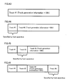
- Figures 33A and 33B show a method for updating the TDFL disclosed in FIG. 9A and FIG. 9B of the reference 1.
- Figure 33A shows a data structure of the TDFL #0.
- the TDFL #0 includes the information regarding defect #1, #2 and #3 corresponding to the defects #1, #2 and #3.
- the TDFL #1 shown in Figure 33B is recorded on the write-once optical disc.
- the TDFL #1 is generated by maintaining the information regarding defect #1, #2 and #3 included in the TDFL #0 and adding the information regarding defect #4 and #5 corresponding to the defects #4 and #5.
- FIG. 10 of the reference 1 shows a data structure of the information regarding defect.
- the information regarding defect includes status information.
- the status information includes information indicating that the defective area is a continuous defect block or a single defect block.
- the information regarding defect further includes a pointer to the defective area (the location of the defective area on the disc).
- the information regarding defect further includes a pointer to the replacement area corresponding to the defective area.
- the status information indicates that a pointer to the defective area designates a start location of the continuous defect block or an end location of the continuous defect block.
- the status information further indicates that a pointer to the replacement area designates a start location of the replacement block or an end location of the replacement block.
- the defective management mechanism can be implemented in the write-once optical disc.
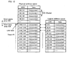
- the physical address at which the data is actually recorded is mapped to another location which is previously allocated, without changing the logical address at which the data is recorded.
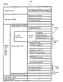
- Figure 31 shows a data structure after directories and files are recorded in the information recording medium 1 which is a write-once optical disc. In the state shown in Figure 31, it is assumed that the pseudo-overwrite recording has not been performed.
- the user data area on the disc is managed as a unit of track or session.
- the user data recorded in the user data area is managed by a file system.
- a space managed by the file system is referred to as a volume space 2.
- information recorded in the information recording medium 1 as the volume/file structure of the file system e.g. descriptor, pointer, metadata partition and metadata file
- descriptor e.g. pointer, metadata partition and metadata file
- UDF Universal Disc Format
- metadata file 6a and metadata mirror file 6b which is the duplication of the metadata file 6a are recorded.
- FE metadata file 7a and FE (metadata mirror file) 7b, each being a file entry (FE) indicating the recording location in the physical partition 4, are recorded. Further, datafile (File-a) 8 and data file (File-b) 9 are also recorded.
- All information on the file structure such as a file entry and directory file is allocated in the metadata partition, i.e. the metadata file.
- the respective recording locations of the metadata partition 5a and the file set descriptor (FSD) 12 are recorded in the volume structure area 3.
- Figure 32 shows a data structure after the pseudo-overwrite recording for data file (File-c) is completed.
- the required information on the file structure is updated or generated in order to add the data file (File-c). Specifically, FE (ROOT) 13 is updated and FE (File-c) 14 is generated, for example.
- the data file (File-c) 15 is recorded in an unrecorded area shown in Figure 31.
- Figure 32 shows a state at this time.
- the FE (File-c) 14 When the FE (File-c) 14 is recorded, the FE (File-c) 14 is recorded in the unrecorded area 11a in the metadata partition 5a (i.e., the metadata file 6a).
- the replacement information included in the disc management information 2 is updated such that the FE (ROOT) 13 is mapped to the FE (ROOT) 16.
- the location information of FE (metadata file) 7a and the location information of FSD 12 are obtained from the volume structure area 3 of the information recording medium 1.
- the file structure is reproduced.
- the FSD 12 is reproduced based on the location information of FE (metadata file) 7a and the location information of FSD 12.
- the location information of the FE (ROOT) 13 is obtained as a logical address from the reproduced FSD 12.
- the FE (ROOT) 13 is reproduced based on the location information of the FE (ROOT) 13.
- the FE (ROOT) 16 By referring to the replacement information, the FE (ROOT) 16, to which the FE (ROOT) 13 is mapped, is reproduced.
- the FE (ROOT) 16 includes the latest ROOT directory file. Accordingly, the FE (ROOT) 16 includes the location information of the FE (File-c) 14.
- the data file (File-c) 15 is reproduced using the location information of the data file (File-c) 15 which is obtained from the FE (File-c) 14.
- the size of the spare area is fixed at the time when the disc is formatted (initialized), unlike the rewritable optical disc in which the size of the spare area can be extended if required.
- the size of the spare area is determined as a relatively large size, the size of the user data area must be reduced. If the size of the spare area is determined as a relatively small size, a problem may be caused. The problem is that it is not possible to further perform the data recording even if there is an unrecorded area in the user data area. In either case, it is not possible to effectively utilize the user data area of the write-once optical disc.
- the present invention is intended to solve the problem described above .
- One of the purposes of the present invention is to provide a drive apparatus capable of utilizing the user data area without any loss in the pseudo-overwrite recording for the write-once optical disc.
- a drive apparatus for performing a sequential recording for a write-once recording medium, wherein the write-once recording medium includes a plurality of ECC clusters, the drive apparatus including: a recording/reproduction section for performing a recording operation or a reproduction operation for the write-once recording medium; and a drive control section for controlling the recording/reproduction section, wherein the drive control section at least performs a process including: receiving a recording instruction at least specifying a location at which data is to be recorded; determining whether a data recording which is performed in accordance with the recording instruction is an appending recording, a first time pseudo-overwrite recording or a second time or more pseudo-overwrite recording; generating data including location information before replacement having information set therein according to the result of the determination; and controlling the recording/reproduction section to record the data in one of the plurality of ECC clusters of the write-once recording medium, the drive control section performs a process including: when the data recording is determined to be the appending recording, setting information indicating that
- a drive apparatus for performing a sequential recording for a write-once recording medium, wherein the write-once recording medium includes a plurality of ECC clusters, each of the plurality of ECC clusters includes a plurality of physical sectors and a plurality of attribute information, the plurality of physical sectors respectively corresponding to the plurality of physical sectors, the drive apparatus including: a recording/reproduction section for performing a recording operation or a reproduction operation for the write-once recording medium; and a drive control section for controlling the recording/reproduction section, wherein the drive control section at least performs a process including: receiving a recording instruction at least specifying data to be recorded and a location at which the data is to be recorded; determining whether or not the data specified by the recording instruction can be recorded in at least one of the plurality of physical sectors included in one of the plurality of ECC clusters; and controlling the recording/reproduction section to record invalid data and the attribute information in each of the at least one physical sector when it is determined that the data specified by the recording instruction
- a drive apparatus for reproducing data recorded in a write-once recording medium, wherein the write-once recording medium includes a plurality of ECC clusters, each of the plurality of ECC clusters includes a plurality of physical sectors, location information before replacement is recorded in each of the plurality of ECC sectors, information indicating that a replacement recording is not performed is set in the location information before replacement when a data recording which is performed in accordance with a recording instruction is an appending recording, information indicating the location specified by the recording instruction is set in the location information before replacement when the data recording which is performed in accordance with the recording instruction is a first time pseudo-overwrite recording; and information indicating a replacement location for the location specified by the recording instruction is set in the location information before replacement when the data recording which is performed in accordance with the recording instruction is a second time or more pseudo-overwrite recording, attribute information is recorded in each of the plurality of physical sectors, first information or second information is set in the attribute information, in an RMW process of reproducing data recorded in
- Figure 1A shows an appearance of information recording medium 100 according to an embodiment of the present invention.
- a lead-in area 101 is located in an inner-most periphery of the information recording medium 100.
- a lead-out area 103 is located in an outer-most periphery of the information recording medium 100.
- a data area 102 is located between the lead-in area 101 and the lead-out area 103 of the information recording medium 100.
- the lead-in area 101 reference information necessary for an optical pickup included in the recording/reproduction section 314 which will be described below to access the information recording medium 100, information for identifying from other recording media, and the like are recorded.
- the lead-out area 103 similar information as those in the lead-in area 101 is recorded.
- a plurality of physical sectors are assigned to the lead-in area 101, the data area 102 and the lead-out area 103.
- Each physical sector is a minimum access unit.
- Each physical sector is identified by an address information such as a physical sector number (hereinafter, "PSN").
- PSN physical sector number
- the data recording/reproduction is performed for each ECC cluster (or each ECC block) including a plurality of physical sectors.
- An ECC cluster (or an ECC block) is a minimum unit for the data recording/reproduction.
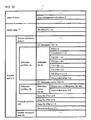
- Figure 1B shows a data structure of the information recording medium 100.
- the lead-in area 101, the data area 102 and the lead-out area 103 are shown in a lateral arrangement, although they are actually arranged in a concentric circular manner as shown in Figure 1A.
- the lead-in area 101 includes a disc management information area 104.
- the lead-out area 103 includes a disc management information area 105.
- Disc management information is recorded in each of the disc management information areas 104 and 105.
- the disc management information includes replacement management information, session management information, and space bitmap management information. This information will be described below.
- the disc management information areas 104 and 105 are used as an area for updating the disc management information.
- the area for updating the disc management information is also referred to as a temporal disc management information area.
- the term “discmanagement information area” in the present specification should be read as a "Disc Management Area (DMA)”
- the term “temporal disc management information area” in the present specification should be read as a “Temporal Disc Management Area (TDMA)”
- the term “disc management information” in the present specification should be read as a “Disc Management Structure (DMS)”
- the term “ temporal disc management information” in the present specification should be read as a “Temporal Disc Management Structure (TDMS)”.
- the data area 102 includes an inner spare area 106, a user data area 108 and an outer spare area 107.
- the user data area 108 is an area used for recording a user data.
- Figure 1C shows a data structure of the user data area 108.
- the user data area 108 includes a plurality of sessions. Each session includes a plurality of tracks.
- Each track is a contiguous area on the information recording medium 100.
- Each track is managed by track management information which will be described below.
- Each session includes a plurality of tracks which are contiguously allocated on the information recording medium 100.
- Each session is managed by session management information which will be described below.
- Figure 2A shows a data structure of the session management information 200 for managing the session.
- the session management information 200 is included in the disc management information.
- the session management information 200 includes header information 201 and a plurality of track management information.
- the header information 201 includes general information such as an identifier of the session management information 200 and the number of the track management information 210 shown in Figure 2B.
- the track management information #N contains information corresponding to the track #N shown in Figure 1C, where N denotes an integer greater than or equal to 1.
- Figure 2B shows a data structure of the track management information 210 for managing the track.
- the track management information 210 is included in the disc management information.
- the track management information 210 includes session start information 211 which indicates whether or not the track is a leading track of the session, track start location information 212 which indicates a start location of the track, and last recorded address information within track 213 which indicates a location at which data has been lastly recorded within the track.
- the last recorded address information within track 213 is referred to as LRA 213.
- a value e.g. "1" indicating that the track is located at a leading position of the session is set to session start information 211. Otherwise, a different value (e.g. "0") is set to session start information 211 .
- the track start location information 212 includes a physical address indicating a start location of the track.
- the LRA 213 includes a physical address indicating a location at which valid data has been lastly recorded within the track.
- Valid data maybe, for example, user data supplied from the host apparatus 305.
- the LRA 120 and the LRA 121 shown in Figure 1C are an example of the LRA 213.
- the location indicated by the LRA 213 does not always match the boundary of ECC clusters.
- the size of data specified by the recording instruction does not match multiple integral of the size of one ECC cluster.
- the LRA 213 indicates an address of the last physical sector among the physical sectors in which the data specified by the recording instruction is recorded.
- padding data is recorded after the valid data so that the end of the recorded data can match the boundary of ECC clusters.
- the data recording can be performed for each track.
- the recording of new data is started from a leading position of each track, and the new data is contiguously recorded within the track (a sequential recording).
- the location at which the data has been lastly recorded within the track is reflected to the LRA 213.
- a value of the LRA 213 is checked. By checking the value of the LRA 213, it is possible to determine a next writable address within the track.
- a predetermined value e.g. "0" indicating such a status can be set to the LRA 213.
- a next writable address (hereinafter, "NWA") indicates a location of a physical sector which is next to the physical sector indicated by the LRA 213.
- the NWA indicates a location of a leading position of an ECC cluster which is next to the ECC cluster including the physical sector indicated by the LRA 213.
- the location of the NWA is calculated according to Expression (1) below.
- the NWA indicates a leading position of the ECC cluster.
- a track where it is possible to record data is referred to as an open track.
- the track number of the open track is included in the header information 201 of the session management information 200 shown in Figure 2A (for example, a first open track number 203, a second open track number 204, etc.).
- Any track other than the open track is referred to as a closed track.
- a track which does not include any unrecorded area or a track designated by a user can be a closed track.
- the track number of the closed track is not stored in the header information 201 of the session management information 200.
- these managements are realized by utilizing the space bitmap management information 220 shown in Figure 2C and the disc management information recorded in the disc management information area 104 and 105.
- the space bitmap management information 220 shown in Figure 2C is recorded in the disc management information area 104.
- Figure 2C shows a data structure of space bitmap management information 220.
- the space bitmap management information 220 includes header information 221, managed area information 222 and space bitmap information 223.
- the header information 221 includes general information such as an identifier of the space bitmap management information 220.
- the managed area information 222 includes information which specifies an area in the user data area 108, wherein the recorded/unrecorded status of a sector included in the area is managed by the space bitmap management information 220.
- the managed area information 222 includes a start location of the area and a length of the area .
- the space bitmap information 223 includes information indicating whether each ECC cluster included in the area to be managed is a recorded ECC cluster or an unrecorded ECC cluster. For example, a single bit data is assigned to each ECC cluster, a predetermined value (e.g. "0") is set to the single bit data when the ECC cluster is an unrecorded ECC cluster, and a predetermined value (e.g. "1") is set to the single bit data when the ECC cluster is a recorded ECC cluster. This makes it possible to manage unrecorded areas for all ECC clusters in the area to be managed.
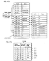
- the disc management information recorded in the disc management information area 104 includes disc structure information 1100 shown in Figure 3.
- the disc structure information 1100 includes last recorded address information 1107.
- the last recorded address information 1107 includes a physical address indicating a location at which data has been lastly recorded within the user data area 108.
- the disc structure information 1100 further includes general information 1101 concerning an entire disc structure information 1100, replacement management information list location information 1102 which indicates location information of the latest replacement management information list 1000 within the disc management information area 104, 105, user area start location information 1103 which indicates a start location of the user data area 108, user area end location information 1104 which indicates an end location of the user data area 108, disc management information area size 1107b, and spare area information 1105 and spare area management information 1108 which indicates the size of the inner spare area 106 and the outer spare area 107 and an area available for replacement.
- replacement management information list location information 1102 which indicates location information of the latest replacement management information list 1000 within the disc management information area 104, 105
- user area start location information 1103 which indicates a start location of the user data area 108
- user area end location information 1104 which indicates an end location of the user data area 108
- disc management information area size 1107b disc management information area size 1107b
- spare area information 1105 and spare area management information 1108 which indicates the size of
- the disc management information area size 1107b By using the disc management information area size 1107b, it is possible to change the size of the disc management information area for each information recording medium. Further, by using the disc management information area size 1107b, it is possible to change the temporal disc management information area described above in the inner- spare area 106 and the outer spare area 107 .
- the spare area information 1105 it is possible to change the size of the spare area for each information recording medium. For example, it is possible to set the size of the inner spare area 106 or the size of the outer spare area 107 to zero.
- the spare area management information 1108 includes next available location information indicating a next available location in the inner spare area 106 and the outer spare area 107.
- each spare area In each spare area, a sequential recording is performed in the same way in each track.
- the next available location in each spare area performs the similar function as the NWA in each track.
- the recording of new data to each spare area is performed sequentially from the location indicated by the next available location information.
- the disc structure information 1100 further includes session management information location information 1109 which indicates location information of the latest session management information 200 in the disc management information areas 104 and 105, and space bitmap management information location information 1110 which indicates location information of the latest space bitmap management information 220 in the disc management information areas 104 and 105.
- the session management information 200 or the space bitmap management information 220 it is possible to manage the status of unrecorded physical sectors on the information recording medium 100. Accordingly, it is possible to selectivelyuse one of the session management information 200 and the space bitmap management information 220 for its purposes. Alternatively, it is possible to use both information.
- the information concerning a method for managing unrecorded areas is included in the recording mode information 1106 of the disc structure information 1100.
- the disc management information area 105 is an extended area which is used to record duplication of the disc management information recorded in the disc management information area 104 or is used to record the information which cannot be recorded in the disc management information area 104 in updating the disc management information.
- the detailed description of the disc management information area 105 will be omitted. This is similar to the temporal disc management information recorded in the spare area.
- the user data recorded in the user data area 108 is managed by a file system.
- a space managed by the file system is referred to as a volume space 109.
- a plurality of logical sectors are assigned to the volume space 109.
- Each logical sector is identified by address information such as a logical sector number (hereinafter, "LSN").
- information recorded in the information recording medium 100 as the volume/file structure of the file system e.g. descriptor, pointer, metadata partition and metadata file
- the volume/file structure of the file system e.g. descriptor, pointer, metadata partition and metadata file
- UDF Universal Disc Format
- the information recording medium 100 shown in Figures 1A to 1C is described as an information recording medium having a single recording layer. However, the information recording medium 100 may have two or more recording layers.
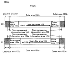
- Figure 4 shows a data structure of an information recording medium 100b having two recording layers.
- L0 denotes a first layer and L1 denotes a second layer
- the lead-in area 101 is located in an inner-most periphery of the first layer and the lead-out area 103a is located in an inner-most periphery of the second layer.
- the outer area 103b is located in an outer-most periphery of the first layer and the outer area 103a is located in an outer-most periphery of the second layer.
- the lead-in area 101, the outer area 103b, the lead-out area 103a and the outer area 103c includes a disc management information area 104, 105, 104a and 105a, respectively.
- the spare areas 106, 106a, 107 and 107a are provided. As described above, it is possible to change the size of each spare area for each information recording medium. It is also possible to provide an additional temporal disc management information area in each spare area.
- the user data areas 108 and 108a are logically treated as a single volume space having contiguous logical addresses.
- an information recording medium having a plurality of recording layers is described. It is possible to apply the description of the information recording medium having a single recording layer to an information recording medium having a plurality of recording layers. Therefore, an information recording medium having a plurality of recording layers is referred to only when a special description is required.
- the replacement information is defined as a replacement management information list (or a defect list) including replacement management information (or a defect list entry).
- the replacement management information (or the defect list entry) includes original location information indicating a location of a cluster in which a defect occurs on the information recording medium (i.e. a defective cluster) and replacement location information indicating a location of a replacement cluster which is used instead of the defective cluster.
- the present invention enables recording a replacement cluster in the user data area.
- the present invention realizes a pseudo-overwrite recording on a write-once information recording medium using the replacement information.
- the data area 102 includes the inner spare area 106, the user data area 108 and the outer spare area 107.
- At least a part of the inner spare area 106 and the outer spare area 107 is used as an area for replacement recording of the data to be recorded in the user data area 108.
- the inner spare area 106 and the outer spare area 107 is used as an area for recording a replacement cluster with which the defective cluster is replaced.
- At least apart of the inner spare area 106 and the outer spare area 107 can be used as an area for recording the updated data in the pseudo-overwrite recording described below.
- the replacement recording which is the combination of the replacement information with the spare area, is performed as well as a verify process.
- the verify process is a process including the steps of reproducing data immediately after the data is recorded, comparing the reproduced data with the recorded data and determining whether or not the data is recorded correctly based on the comparison result. Such a process including these steps is called a verify-after-write process.
- a replacement recording is performed. Specifically, the defective cluster is replaced by a replacement cluster and the data is recorded in the replacement cluster.
- the replacement cluster is recorded in the inner spare area 106 (or the outer spare area 107) or the user data area 108.
- the pseudo-overwrite recording is defined as a method for mapping a physical address at which the data is actually recorded to another physical address, such that it can be seen as if the logical address at which the data is recorded is not changed.
- the replacement cluster used in the pseudo-overwrite recording is recorded in the spare area or the user data area.
- the replacement management information list 1000 shown in Figure 5A is used as the replacement information for performing such a mapping process.
- this recording method is referred to as a pseudo-overwrite recording.
- FIG. 5A shows a data structure of a replacement management information list 1000 which is replacement information according to the present invention.
- the replacement management information list 1000 is used to map the location of the defective cluster to the location of the replacement cluster.
- the replacement management information list 1000 includes header information 1001 and a plurality of replacement management information 1010 (e.g. replacement management information #1, #2, #3).
- the header information 1001 includes the number of the replacement management information included in the replacement management information list 1000.
- the replacement management information includes information indicating the mapping described above.
- FIG. 5B shows a data structure of the replacement management information 1010.
- the replacement management information 1010 includes status information 1011, original location information 1012 and replacement location information 1013.
- the status information 1011 includes status information concerning the mapping described above.
- the status information indicates a type or an attribute of the replacement management information 1010, the valid/invalid status of the original location information 1012 and the replacement location information 1013 and like.
- the original location information 1012 indicates a location of original information (e.g. a defective cluster).
- the replacement location information 1013 indicates a location of replacement information (e..g. a replacement cluster).
- the location of the ECC cluster before overwrite is indicated by the original location information 1012, and the location of the ECC cluster after overwrite is indicated by the replacement location information 1013.
- the location of the ECC cluster before overwrite is mapped to the location of the ECC cluster after overwrite.
- the original location 1012 and the replacement location information 1013 registered in the replacement management information 1010 may be represented by a physical address (e.g. PSN) of the first sector in the corresponding ECC cluster. This is because a mapping is performed as a unit of ECC cluster in the defective management and the pseudo-overwrite recording.
- PSN physical address
- the replacement cluster is recorded in the spare area. Accordingly, in every case, the information indicating a location of the ECC cluster in the spare area is set to the replacement location information 1013.
- the location at which the replacement cluster can be recorded is not limited to the location in the spare area. It is possible to record the replacement cluster in the user data area. Accordingly, the information indicating a location of the ECC cluster in the spare area or the information indicating a location of the ECC cluster in the user data area may be set to the replacement location information 1013.
- the replacement location information 1013 may indicate a location of the ECC cluster recorded in one of two areas (i.e. the spare area and the user data area). In order to determine whether the replacement location information 1013 indicates a location of the ECC cluster in the spare area or a location of the ECC cluster in the user data area, information indicating one of the two cases may be defined. Such information may be incorporated into the status information 1011.
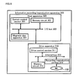
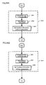
- Figure 6 shows a configuration of an information recording/reproduction apparatus 300 according to an embodiment of the present invention.
- the information recording/reproduction apparatus 300 includes a host apparatus 305 and a drive apparatus 310.
- the host apparatus 305 can be, for example, a computer system or a personal computer.
- the drive apparatus 310 can be, for example, any one of a recording apparatus, a reproduction apparatus and a recording/reproduction apparatus.
- the information recording/reproduction apparatus 300 as a whole also can be called any one of a recording apparatus, a reproduction apparatus and a recording/reproduction apparatus.
- the host apparatus 305 includes a system control section 301 and a memory circuit 302.
- the host apparatus 305 may further include magnetic disc apparatus 304 such as a hard disc drive.
- the components in the host apparatus 305 are connected to each other via an I/O bus 303.
- the system control section 301 can be implemented, for example, by a microprocessor including a system control program and a memory for operation.
- the system control section 301 controls various processes and performs various operations such as recording/reproduction of a volume structure/file structure of a file system, recording/reproduction of a metadata partition/file structure described below, recording/reproduction of files and recording/reproduction of the lead-in/lead-out areas.
- the memory circuit 302 is used to operate information such as a volume structure, a file structure, a metadata partition/file structure and files, and is used to temporarily store them.
- the drive apparatus 310 includes a drive control section 311, a memory circuit 312, and a recording/reproduction section 314. The components in the drive apparatus 310 are connected to each other via an internal bus 313.
- the drive control section 310 can be implemented, for example, by a microprocessor including a drive control pr ogram and a memory for operation .
- the drive control section 310 controls various processes and performs various operations such as recording/reproduction of the disc management information area and the spare area and the pseudo-overwrite recording/reproduction.
- the system control section 301 and drive control section 310 shown in Figure 6 can be implemented by a semiconductor integrated circuit such as an LSI. Alternatively, they can be implemented by a general processor and a memory (e.g. a ROM).
- a program is stored in the memory (e.g. a ROM).
- the program is executable by a computer (e.g. a general processor).
- This program may represent a reproduction process and/or a recording process according to the present invention described above or described below.
- a computer e.g. a general processor
- the memory circuit 312 is used to operate data concerning the disc management information area and the spare area and data transferred to the drive apparatus 310, and is used to temporarily store them.
- Track #1 401, track #2 402 and track #3 403 are allocated in the user data area 108.
- a volume space 109 is allocated in the user data area 108.
- a volume structure area 410, a physical partition 420 and a volume structure area 411 are allocated in the volume space 109.
- a metadata partition 430 is included in the physical partition 420.
- the metadata partition 430 is defined in a pseudo-overwrite method in version 2.5 or higher version of the UDF specification.
- a metadata file 440 is recorded.
- the metadata mirror file is a duplication of metadata file 440.
- the metadata mirror file can be also recorded.
- a FE (Metadata file) 441 is recorded.
- the FE (Metadata file) 441 is a file entry (FE) indicating a recording location of the metadata file 440 in the physical partition 420.
- the information on the file structure such as a file entry (FE) indicating a recording location of a user data file or a directory, is located in the metadata partition 430 (i.e. the metadata file 440).
- FE file entry
- the method for allocating tracks is not limited to the method shown in Figure 7. For example, more tracks can be allocated. It is possible to add a new track when it is required, while maintaining the state of the last track in the user data area such that the new track can be added to the last track.
- a plurality of physical addresses are assigned to the data area 102 of the information recording medium 100.
- a plurality of logical addresses are assigned to the user data area 108 of the information recording medium 100. It is assumed that a corresponding relationship between the plurality of logical addresses and the plurality of physical addresses is predetermined.
- Each of the plurality of logical addresses is represented by a logical sector number (LSN) or a logical block address (LBA).
- Each of the plurality of physical addresses is represented by a physical sector number (PSN) or physical block address (PBA). Further, it is assumed that at least one track is allocated in user data area 108.
- Step S101 Prior to recording the data file (File-a), the drive control section 311 performs a preparation process for the data recording. Such a preparation process for the data recording is performed, for example, when the information recording medium 100 is loaded into the drive apparatus 310.
- the drive control section 311 reads the latest disc management information from the disc management information area 104 (or the disc management information area 105) of the information recording medium 100.
- the drive control section 311 obtains the user area start location information 1103, the user area end location information 1104, the spare area information 1105 and like from the disc management information in order to determine a primary logical address-physical address mapping indicating the corresponding relationship between the plurality of logical addresses and the plurality of physical addresses assigned to the user data area 108.
- the drive control section 311 performs translation between the logical address and primary physical address in accordance with the primary logical address-physical address mapping.
- the drive control section 311 obtains track management information included in the disc management information area 104.
- the drive control section 311 receives a recording instruction from the host apparatus 305.
- the recording instruction includes a logical address indicating a location at which data is to be recorded. This logical address is represented, for example, by a logical sector number (LSN) or a logical block address (LBA).
- LSN logical sector number
- LBA logical block address
- the recording instruction may include a single logical address indicating a location at which single data is to be recorded, or it may include a plurality of logical addresses indicating a plurality of locations at which a plurality of data are to be recorded respectively.
- the logical address included in the recording instruction is determined, for example, by the host apparatus 305 based on a logical address indicating a location at which data is to be recorded the next time (i.e. a logical next writable address (a logical NWA)).
- a logical next writable address a logical NWA
- the logical NWA is output from the drive apparatus 310 to the host apparatus 305 in response to a request from the host apparatus 305 to the drive apparatus 310, for example.
- the logical NWA is obtained by translating the NWA determined by Expression (1) described above in accordance with the primary logical address-physical address mapping. This translation is performed by the drive control section 311.. The procedure for determining the NWA and the logical NWA will be described later in detail in embodiment 2 of the invention.
- the system control section 301 of the host apparatus 305 generates and updates file system information as necessary in order to record data file (File-a). For example, the system control section 301 generates an FE (File-a) for the data file (File-a) and updates the ROOT directory which is a parent directory of the data file (File-a) using the memory circuit 302.
- FE File-a
- ROOT directory which is a parent directory of the data file (File-a) using the memory circuit 302.
- the generated FE (File-a) for the data file (File-a) and the updated ROOT directory are recorded in the information recording medium 100 by outputting the recording instruction from the host apparatus 305 to the drive apparatus 310.
- the latest file system information is reflected on the information recording medium 100.
- the host apparatus 305 inquires the drive apparatus 310 using a predetermined command as to whether or not there is any remaining unrecorded area for performing a replacement recording.
- the instructions from the host apparatus 305 to the drive apparatus 310 may be a standardized command such as a SCSI multi-media command.
- a request for the logical NWA may be a READ TRACK INFORMATION command
- a recording instruction may be a WRITE command
- Step S103 The drive control section 311 translates the logical address included in the recording instruction received in step S102 into a physical address in accordance with the primary logical address-physical address mapping.
- Step S104 The drive control section 311 determines a track (an open track) of the at least one track allocated in the user data area 108 based on the physical address corresponding to the logical address included in the recording instruction and the track management information 210 ( Figure 2B) included in the disc management information.
- the drive control section 311 determines a physical address indicating a location at which data is to be recorded the next time (i.e. NWA) within the determined track, based on LRA 213 within the determined track.
- NWA is a next writable address determined in accordance with Expression (1) described above.
- the NWA may be determined in step S104.
- the NWA may be determined in other steps other than step S104 (e.g. in the preparation process for the data recording described above)
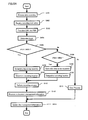
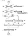
- Step S105 The drive control section 311 determines whether or not the physical address corresponding to the logical address included in the recording instruction is less than the NWA.
- the recording instruction is determined as a recording instruction for the recorded area in the user data area 108. In this case, the process proceeds to step S106. Otherwise, the process proceeds to step S108 .
- Step S106 The drive control section 311 determines data to be recorded.
- the drive control section 311 determines the data specified by the recording instruction as the data to be recorded. For example, if the recording location and the size of the data specified by the recording instruction match a boundary of the ECC clusters, then an entire ECC cluster is rewritten. In this case, the drive control section 311 determines the data itself specified by the recording instruction as the data to be recorded.
- the drive control section 311 performs a read-modify-write process described below. In this case, the drive control section 311 determines the data as a unit of ECC cluster which is obtained during the read-modify-write process as the data to be recorded.
- Step S107 The drive control section 311 determines the recording location of the data determined in step S106. Specifically, the drive control section 311 determines a specific location in the user data area 108, which is other than the location indicated by the physical address corresponding to the logical address included in the recording instruction, as the recording location of the data determined in step S106.
- the specific location may be the NWA within the track determined in step S104.
- the specific location may be a location indicated by an NWA within an open track which is different from the track determined in step S104.
- the NWA within the open track is an NWA which indicates a location which is closest to the location indicated by the physical address corresponding to the logical address included in the recording instruction.
- Step S108 The drive control section 311 determines whether or not the physical address corresponding to the logical address included in the recording instruction is equal to the NWA.
- the recording instruction is determined as a recording instruction to the location indicated by the NWA. That is, the data recording instructed by the recording instruction is determined as an appending recording (a new recording). In this case, the process proceeds to step S109. Otherwise, the process proceeds to step S111.
- Step S109 The drive control section 311 determines data to be recorded. Specifically, the drive control section 311 determines the data specified by the recording instruction as the data to be recorded.
- the drive control section 311 determines whether or not the end of the data specified by the recording instruction matches a boundary of the ECC clusters. If it does not match the boundary of the ECC clusters, padding data (e.g. data consisting of one or more "00"h) is inserted such that the end of the data after insertion matches the boundary of the ECC clusters. In this case, the drive control section 311 determines the data after insertion as the data to be recorded.
- padding data e.g. data consisting of one or more "00"h
- Step S110 The drive control section 311 determines the recording location of the data determined in step S106. Specifically, the drive control section 311 determines the location indicated by the physical address corresponding to the logical address included in the recording instruction (i.e. the location indicated by the NWA), as the recording location of the data determined in step S106.
- Step S111 The drive control section 311 performs an error process.
- Step S112 The drive control section 311 performs a recording process for the determined recording location.
- step S105 determines whether the determination result in step S105 is "Yes"
- the drive control section 311 controls the recording/reproduction section 314 to record the data determined in step S106 at the recording location determined in step S107.
- step S108 determines whether the determination result in step S108 is "Yes"
- the drive control section 311 controls the recording/reproduction section 314 to record the data determined in step S109 at the recording location determined in step S110.
- the drive control section 311 performs a verify process for the recorded data to determine whether or not the data recording has succeeded. If the data recording has succeeded, then the process proceeds to step S113.
- an unrecorded area in the spare area e.g. the inner spare area 106 or the user data area 108 is allocated as a replacement cluster, and the data is recorded in the replacement cluster.
- step S113 After the data recording has finally succeeded, the process proceeds to step S113.
- step S106 and step s112 described above is performed as a read-modify-write process (hereinafter RMW process).
- RMW process read-modify-write process
- the drive control section 311 controls the recording/reproduction section 314 to reproduce the data recorded in the ECC cluster including a physical sector at a location indicated by the physical address corresponding to the logical address included in the recording instruction, and it stores the data reproduced from the ECC cluster in the memory circuit 312 (i.e. "read" process).
- the drive control section 311 refers to the replacement management information list 1000, and, if necessary, it controls the recording/reproduction section 314 to reproduce the data recorded in the replacement cluster.
- the procedure of the data reproduction referring to the replacement management information list 1000 will be described later.
- the drive control section 311 replaces the data recorded in the physical sector at the location indicated by the physical address corresponding to the logical address included in the recording instruction among the data reproduced from the ECC cluster with the data included in the recording instruction (i.e. "modify" process). As a result, the data to be recorded in the replacement cluster is obtained.
- the drive control section 311 performs a read process and a modify process in step S106.
- Figure 8B shows the steps performed when the read process and the modify process are performed in step S106 shown in Figure 8A. Each step shown in Figure 8B is performed by the drive control section 311 of the drive apparatus 310.
- Step S151 The drive control section 311 determines whether or not the ECC cluster including the location specified by the recording instruction has been already replaced by a replacement cluster. Such a determination is made, for example, by retrieving the replacement management information list 1000.
- step S152A If the replacement management information 1010 which indicates the location specified by the recording instruction as original location is found, it is determined that the ECC cluster has been already replaced by the replacement cluster and the process proceeds to step S152A. Otherwise, the process proceeds to step S152B.
- step S151 By holding the determination result of step S151 as a value of the internal variable, it is possible to refer to the value of the internal variable. By referring to the value of the internal variable, if necessary, in the steps other than step S151, it is possible to determine whether or not the ECC cluster including the location specified by the recording instruction has been already replaced by a replacement cluster. This makes it possible to avoid repeatedly performing the same process. For example, if the determination result of step S151 is "Yes”, then the value of "1" may held as the value of the internal variable, and if the determination result of step S151 is "No", then the value of "0" may held as the value of the internal variable.
- Step S152A The drive control section 311 determines whether or not the RMW process is required. For example, if the location and the size specified by the recording instruction matches a boundary of the ECC clusters, then drive control section 311 determines that the RMW process is not required. If the location and the size specified by the recording instruction do not match any boundary of the ECC clusters , then drive control section 311 determines that the RMW process is required.
- step S153 If it is determined that the RMW process is required, then the process proceeds to step S153. Otherwise, the process proceeds to step S157.
- step S152A Similar to step S151, by holding the determination result of step S152A as a value of the internal variable, it is possible to refer to the value of the internal variable. By referring to the value of the internal variable, if necessary, in the steps other than step S152A, it is possible to determine whether or not the RMW process is required.
- Step S152B The drive control section 311 determines whether or not the RMW process is required. The process of step S152B is the same as the process of step S152A.
- step S154 If it is determined that the RMW process is required, then the process proceeds to step S154. Otherwise, the process proceeds to step S157 .
- Step S153 The drive control section 311 controls the recording/reproduction section 314 to reproduce the data recorded in the replacement cluster indicated by the replacement management information 1010 found in step S151, instead of the ECC cluster including the location specified by the recording instruction, and stores the reproduced data in the memory circuit 312.
- Step S154 The drive control section 311 controls the recording/reproduction section 314 to reproduce the data recorded in the ECC cluster including the location specified by the recording instruction, and stores the reproduced data in the memory circuit 312.
- Step S155 The drive control section 311 replaces the reproduced data by the data specified by the recording instruction so as to generate a modified data.
- Step S156 The drive control section 311 determines the modified data as the data to be recorded in the information recording medium 100.
- Step S157 The drive control section 311 determines the data specified by the recording instruction as the data to be recorded in the information recording medium 100.
- the drive control section 311 controls the recording/reproduction section 314 to record the data obtained as a result of the modify process (i.e. the data to be recorded in the replacement cluster) in a location of the original ECC cluster (i.e. "write" process).
- the drive control section 311 performs write process in step S112.
- the information recording medium is awrite-once recording medium, it is not possible to actually record the data in a location of the original ECC cluster.
- an unrecorded area in the spare area such as the inner spare area 106 or the user data area 108 is allocated as a replacement cluster, and the updated data is recorded in the replacement cluster.
- the drive control section 311 performs a verify process to determine whether or not the data recording has succeeded. When it is determined that the data recording has succeeded, the process proceeds to step S113.
- an unrecorded area in the spare area such as the inner spare area 106 or the user data area 108 is allocated as a further replacement cluster, and the data is recorded in the further replacement cluster.
- step S113 After the data recording has finally succeeded, the process proceeds to step S113.
- the entire ECC block is rewritten. In this case, the read process described above is not required.
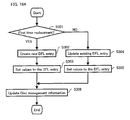
- Step S113 The drive control section 311 generates replacement management information 1010 in accordance with the process in step S112, and stores the replacement management information 1010 in memory circuit 312. For example, in step S112, when the drive control section 311 controls the recording/reproduction section 314 to record data at a specific location in the user data area 108 wherein the specific location is any location other than the location indicated by the physical address corresponding to the logical address included in the recording instruction, the drive control section 311 generates replacement management information 1010 which maps the physical address corresponding to the logical address included in the recording instruction to a physical address indicating the specific location.
- the drive control section 311 updates the replacement management information 1010 so as to set the physical address indication of the specific address as a new replacement location information 1013.
- the drive control section 311 If it is not found, the drive control section 311 generates new replacement management information 1010 and adds the new replacement management information 1010 to the replacement management information list 1000.
- the drive control section 311 sorts the replacement management information list 1000. For example, the drive control section 311 sorts the replacement management information list 1000 by the status information 1011, and then sorts it by the physical address indicated by the original location information 1012.
- a new replacement management information list 1000 including the replacement management information 1010 which maps the physical address corresponding to the logical address included in the recording instruction to the physical address indicating the specific location is generated.
- Step S114 The drive control section 311 updates the disc management information to reflect the recording process described above. For example, the drive control section 311 updates the last recorded address information 1107. In addition, the drive control section 311 updates the LRA 213 in each track management information 210 corresponding to the tracks in which data have been recorded to reflect the latest recording status.
- the drive control section 311 generates the new disc management information including the updated information such as the new replacement management information list 1000 and track management information 210.
- the drive control section 311 sets the replacement management information list location information 1102 and the session management information location information 1109 included in the new disc management information to indicate the latest recording location of the new replacement management information list 1000 and track management information 210 on the information recording medium 100.
- the drive control section 311 controls the recording/reproduction section 314 to record the new disc management information in a predetermined area (e.g. a temporal disc management information area) on the information recording medium 100.
- a predetermined area e.g. a temporal disc management information area
- the disc management information is updated to reflect the latest status.
- the drive apparatus 310 can notify the host apparatus 305 of the result of the recording process.
- the result of the recording process is, for example, information indicating that the data recording has succeeded or failed.
- Such a notification can be sent to the host apparatus 305 at a predetermined timing. For example, it is possible to send this notification to the host apparatus 305 at the timing of the end of step S108 or at the timing when an error occurs in step S112. Alternatively, it is possible to send this notification before the data recording is actually completed.. For example, it is possible to send anotification indicating that the data recording is completed to the host apparatus 305 at the timing when the interpretation of the received record instruction is completed correctly.
- the replacement recording process it is possible to retrieve an unrecorded area in a direction along which the PSNs are increased from the location of the original ECC cluster. If the unrecorded area is found during the retrieval, the unrecorded area is allocated as a replacement cluster.
- the retrieval for the unrecorded area reaches the end of the outer spare area 107 without finding any unrecorded area, it is possible to retrieve an unrecorded area in a direction along which the PSNs are increased from a predetermined location at the inner side of the information recording medium 100 (e.g. a leading position of the inner spare area 106 or a leading position of the user data area 108 or a location apart from its leading position by a predetermined distance).
- a predetermined location at the inner side of the information recording medium 100 e.g. a leading position of the inner spare area 106 or a leading position of the user data area 108 or a location apart from its leading position by a predetermined distance.
- steps S105 and S108 of the procedure of the recording process it is determined whether the data recording is a pseudo-overwrite recording or an appending recording by comparing the physical address corresponding to the logical address included in the recording instruction with the NWA.
- the reason why it is determined whether the data recording is a pseudo-overwrite recording or an appending recording based on such a comparison is that the information recording medium 100 is a write-once recording medium and that a sequential recording is performed for the write-once recording medium.
- the replacement recording method using the user data area described above according to the present invention is applicable to any rewritable optical disc.
- a more complex process is required. This is because, in the case of the rewritable optical disc, it is possible to randomly rewrite data at an arbitrary location on the optical disc.
- the drive apparatus manages an unrecorded area on the rewritable optical disc as described in the embodiment above, it is necessary to manage replacement management information corresponding to all ECC clusters on the rewritable optical disc using the SDL, as described in the background art of the present specification, for example. Further, in order to determine whether the data recording for recording data at a certain location in the user data area is an overwrite recording or a new recording, it is necessary to retrieve an entire replacement management information list 1000, for example. Similarly, in order to determine whether or not an ECC cluster is used as a replacement cluster, it is necessary to retrieve an entire replacement management information list 1000. The amount of such a retrieving process is increased as the size of the replacement management information list 1000 is increased. This should be a problem since the capacity of the optical disc is being increased more and more.
- the information recording medium 100 is a write-once recording medium, it is ensured that every area in a track which has an address less than the NWA is an unrecorded area.
- steps S105 and S108 it is possible to easily determine whether the data recording is a pseudo-overwrite recording or an appending recording, regardless of the size of the replacement management information list 1000. Further, it is possible to easily select a replacement cluster since the replacement cluster can be selected from any location after the NWA.
- the pseudo-overwrite recording in a random recording method for a write-once optical disc is performed in a similar way as the rewritable optical disc.
- a special structure such as the space bitmap management information 220 is required.
- the management of the unrecorded area for the random recording method using the space bitmap management information 220 requires significantly greater processing load to the drive control section 311, compared to the management of the unrecorded area for the sequential recording method.
- the sequential recording method it is possible to limit the number of open tracks to a predetermined number (for example, four at maximum) so that the utilization of a file system is not reduced.
- the number of open tracks depends on the structure of the file system, and it is independent from the capacity of the optical disc.
- the size of the space bitmap management information 220 is increased as the capacity of the optical disc is increased. As a result, the processing load is also increased.
- the effect of the present invention for performing a pseudo-overwrite in the sequential recording method is very significant for the optical disc, since the capacity of the optical disc is being increased more and more.
- One feature of the present invention is to determine an NWA in accordance with LRA 213 included in the latest track management information 210 and expression (1) in order to determine whether the data recording is a pseudo-overwrite recording or an appending recording.
- the following procedure is required, for example.
- the procedure includes the steps of determining a track including a physical address corresponding to the logical address included in the recording instruction, sequentially checking ECC clusters from a leading position of the determined track, and determining whether or not each of the ECC clusters is recorded.
- the ECC cluster is in a recorded state at a location indicated by the recording instruction, then it is determined that the data recording is a pseudo-overwrite recording.
- the present invention it is possible to easily determine whether the data recording is a pseudo-overwrite recording or an appending recording, regardless of the size of the track.
- LRA 213 is included in the track management information 210, it is possible to easily determine an NWA as well as the determination of a track in which the data is to be recorded when the drive apparatus 310 receives the recording instruction.
- Figure 9 shows a data structure on the information recording medium 100 after the data file has been recorded in accordance with the procedure of the data recording.
- data file (File-a) 460 is described as an example of the data file. It is assumed that a defective cluster #1 and a defective cluster #2 are detected in the data file (File-a) 460 in the procedure of the data recording.
- the disc management information including replacement management information indicating a replacement of the defective cluster #1 with a replacement cluster #1 and a replacement management information indicating a replacement of the defective cluster #2 with a replacement cluster #2 is recorded in the disc management information area 104.
- the replacement cluster #1 is recorded in the inner spare area 106 and the replacement cluster #2 is recorded in the user data area 108.
- the content of the data file (File-a) 460 is updated by the pseudo-overwrite recording.
- an overwritten cluster #3 and an overwritten cluster #4 correspond to the updated portions of the data file (File-a) 460 according to the pseudo-overwrite recording.
- the new data updated by the pseudo-overwrite recording is recorded in a replacement cluster #3 assigned as the substitute for the overwritten cluster #3 and is recorded in a replacement cluster #4 assigned as the substitute for the overwritten cluster #4.
- the corresponding replacement information is recorded in the disc management information area 104.
- the replacement cluster #3 is assigned in the inner spare area 106 and the replacement cluster #4 is assigned in the user data area 108..
- Step S201 Prior to performing a reproduction process, the drive control section 311 performs a preparation process for the data reproduction. Such a preparation process for the data reproduction is performed, for example, when the information recording medium 100 is loaded into the drive apparatus 310.
- the drive control section 311 reads disc management information from the disc management information area 104 (or the disc management information area 105) of the information recording medium 100.
- the drive control section 311 obtains user area start location information 1103, user area end location information 1104, spare area information 1105 and like from the disc management information to generate a primary logical address-physical address mapping indicating the corresponding relationship between the plurality of logical addresses and the plurality of physical addresses assigned to the user data area 108.
- the drive apparatus 310 performs translation between the logical address and the primary physical address in accordance with primary logical address-physical address mapping.
- the AVDP is a data structure defined by the UDF specification as an anchor point of the file system information.
- the AVDP is recorded in the volume structure area 410 and the volume structure area 411.
- Step S203 The system control section 301 obtains location information of a main volume descriptor sequence 410A recorded in the volume structure area 410 from the AVDP.
- the system control section 301 outputs an instruction to the drive apparatus 310 to reproduce the main volume structure 410A.
- system control section 301 obtains location information (LSN) of an FE (metadata file) 441 by retrieving the data structure from the reproduced main volume descriptor sequence 410A in steps,.
- LSN location information
- Step S204 The system control section 301 reproduces a file structure.
- the system control section 301 outputs a reproduction instruction to the drive apparatus 310 based on the obtained location information (LSN) of the FE (metadata file) 441 to reproduce the FE (metadata file) 441.
- the system control section 301 obtains location information of a metadata file 440 from the reproduced FE (metadata file) 441.. As a result, it is possible to access the metadata file 440.
- Step S205 In accordance with the procedure of the data reproduction based on the UDF specification, the FDS 433, the FE (ROOT) 442, the FE (File-a) 443 and the data file (File-a) 460 are reproduced in this order.. The description of the reproduction of the directory file is omitted.
- a reproduction instruction is output from the host apparatus 305 to the drive apparatus 310.
- the drive control section 311 of the drive apparatus 310 receives the reproduction instruction from the host apparatus 305, and performs a reproduction process in accordance with the reproduction instruction.
- the reproduction instruction includes a logical address indicating a location from which data is to be reproduced.
- the logical address is, for example, represented by a logical sector number (LSN).
- the logical address may be represented by a logical block address (LBA).
- the reproduction instruction is, for example, a READ command.
- the drive control section 311 translates the logical address included in the reproduction instruction into a physical address in accordance with the primary logical address-physical address mapping (for example, see Figure 12).
- the drive control section 311 determines whether or not the replacement management Information 1010 having the original location information 1012, which indicates the same location as the physical address corresponding to the logical address included in the reproduction instruction, is found in the replacement management information list 1000 by retrieving the replacement management information list 1000.
- the drive control section 311 refers to the replacement location information 1013 of the replacement management information 1010 and controls the recording/reproduction section 314 to reproduce data from the location indicated by the replacement location information 1013.
- the drive control section 311 controls the recording/reproduction section 314 to reproduce data from the location indicated by the physical address corresponding to the logical address included in the reproduction instruction.
- the reproduced data is sent back to the host apparatus 305.
- Figure 11 shows a data structure of the replacement management information 1010B.
- the replacement management information 1010B is a different embodiment of the replacement management information 1010 shown in Figure 5B.
- the status information 1011 of the replacement management information 1010B includes three information, i.e. Flag1, Flag2 and Flag3.
- Flag1 is information for classifying the replacement management information 1010B. Flag1 includes information indicating whether the replacement information is for the purpose of the replacement recording or for the purpose of the designation of the defective cluster.
- Flag2 is information on the recording location of the replacement cluster managed by the replacement management information 1010B . Flag2 includes information indicating whether the recording location of the replacement cluster is in the spare area (or there is no replacement cluster) or the recording location of the replacement cluster is in the user data area.
- Flag3 is information on the number of the clusters managed by the replacement management information 1010B. Flag3 includes information indicating whether the replacement information corresponds to a single cluster or a plurality of contiguous clusters. When the replacement information corresponds to a plurality of contiguous clusters, Flag3 further includes information indicating whether the replacement information corresponds to a start location of the contiguous range or an end location of the contiguous range.
- This replacement management information (type (1)) may be denoted by the replacement management information (1).
- Figure 12 shows an example of the data structure of the physical address space and the logical address space on the information recording medium 100 according to the present invention.
- Figure 12 also shows a corresponding relationship between the logical sector number (LSN) and the physical sector number (PSN) in a primary state.
- the logical sector number (LSN) is a logical address indicating a location which is seen from the host apparatus 305 on the information recording medium 100.
- the physical sector number (PSN) is a physical address indicating an actual location on the information recording medium 100.
- This corresponding relationship is referred to as a primary logical address-physical address mapping. This mapping is represented by broken line arrows in Figure 12 (or other figures).
- Each row shown in Figure 12 corresponds to one ECC cluster.
- a physical address (PSN) and a logical address (LSN) corresponding to the physical address (PSN) are shown in the same row.
- the values of the PSNs and the LSNs are shown as the values of the PSNs and the LSNs from the first sector to the last sector in the corresponding ECC cluster.
- one ECC cluster consists of 32 sectors.
- one ECC cluster may be any other configuration.
- the PSNs are assigned to the inner spare area 106, the outer spare area 107 and the user data area 108.
- the tracks are allocated from a leading position of the user data area 108.
- the LRA 500 designates a leading position of the user data area 108.
- the LSNs are assigned to only the user data area 108 (or the volume space 109).
- the host apparatus 305 instructs a recording process or a reproduction process. These instructions specify a specific logical sector on the information recording medium 100 using the LSN.
- the drive apparatus 310 translates the LSN received from the host apparatus 305 into a PSN using the primary logical address-physical address mapping, and accesses a physical sector or ECC cluster in accordance with the PSN.
- the primary logical address-physical address mapping is basically used.
- the replacement management information 1010 is used.
- the values of the PSNs and the LSNs are only examples for explanation. These values can be varied depending on the structure and the capacity of the information recording medium 100.
- the size of the disc management information and the spare area can be changed.
- the size of these is determined at the time when the format process is performed in response to an instruction from the host apparatus 305. After the format process, the start location and the end location of the user data area 108 is not changed.
- the drive apparatus 310 performs a verify process for the recorded data.
- the drive apparatus 310 generates replacement management information 511.
- the status information 1011 of the replacement management information 511 is set in accordance with Figure 11.
- the replacement management information 511 corresponds to solid line arrows shown in Figure 13A.
- the tail of each arrow represents the original location of the replacement management information 511 and the head of each arrow represents the replacement location of the replacement management information 511.
- a similar notation will be used.
- the recording of data "B” has failed.
- the replacement management information 512 is generated in response to this replacement recording.
- the status information 1011 of the replacement management information 512 is set in accordance with Figure 11.
- the data allocation and the replacement management information list after the data recording described above is completed are shown in Figure 13A and Figure 13B, respectively.
- the replacement management information (1) is used in the replacement management information list 1000A shown in Figure 13B.
- the replacement management information 513 is generated in response to this replacement recording.
- the replacement management information 514 is generated in response to this replacement recording.
- the replacement management information 514A is generated in response to this replacement recording.
- the replacement management information 514 becomes unnecessary. Accordingly, the replacement management information 514 is deleted from the replacement management information list 1000.
- the location of the LRA is updated to a location indicated by 500B.
- the replacement management information list 1000B ( Figure 14B) is sorted by Flag1 of the status information 1011, and then it is sorted by the value of PSN indicated by the original location information 1012.
- the replacement management information 516 and the replacement management information 517 are generated.
- Each of the replacement management information 516 and 517 indicates the first PSN of the ECC cluster corresponding to a start location of the replacement recording and the first PSN of the ECC cluster corresponding to an end location of the replacement recording.
- the replacement management information 516A is generated as information indicating a start point of the replacement recording.
- the replacement management information 517A is generated as information indicating an end point of the replacement recording.
- the replacement management information 516 and 517 become unnecessary. Accordingly, the replacement management information 516 and 517 are deleted from the replacement management information list 1000.
- the updated replacement management information list is recorded in the disc management information area.
- the drive control section 311 Prior to performing a reproduction process, the drive control section 311 performs a preparation process for the data reproduction. Such a preparation process for the data reproduction is performed, for example, in a manner similar to step S201 described above.
- the drive apparatus 310 performs the same reproduction process. Specifically, the drive apparatus 310 translates the received LSN into a PSN in accordance with the primary logical address-physical address mapping, and determines whether or not the replacement management information corresponding to the PSN is found in the replacement management information list 1000. If it is found, then the data is reproduced from the replacement cluster . If it is not found, then the data is reproduced from the PSN.
- the user data area 108 as an area for a replacement location without any loss in the pseudo-overwrite recording for the information recording medium 100.
- FIG 18 shows a data structure of a DFL entry 2010.
- the DFL entry 2010 is a different embodiment of the replacement management information 1010 and the replacement management information 1010B described above.
- the DFL entry 2010 includes status 1 2011A, status 2 2011B, a defective cluster first PSN 2012 and a replacement cluster leading PSN 2013.
- the status 1 2011A and the status 2 2011B correspond to the status information 1011 described above.
- the defective cluster first PSN 2012 corresponds to the original location information 1012 described above.
- the replacement cluster first PSN 2013 corresponds to the replacement location information 1013 described above.
- the defective cluster first PNS 2012 and the replacement cluster first PSN 2013 may be represented by a physical address (e.g. PSN) of the first sector in the corresponding ECC cluster. This is because a mapping is performed as a unit of ECC cluster in the defective management and the pseudo-overwrite recording.
- PSN physical address
- the DFL entry 2010 can be applied to all embodiments. With reference to the data structure of the DFL entry 2010 shown in Figure 18 and the flowchart shown in Figure 19A, an exemplary process for the replacement management information in step S113 of Figure 8A will be described in detail.
- step S112 shown in Figure 8A and then the process proceeds to step S113.
- Step S301 It is determined whether the pseudo-overwrite recording is a first time replacement recording or a second time or more replacement recording.
- This determination is performed, for example, by retrieving a DFL entry 2010 having a value of the first PSN of the ECC cluster including the physical address corresponding to the logical address included in the recording instruction as a value of the defective cluster first PSN 2012 in the latest replacement management information list.
- the physical address corresponding to the logical address included in the recording instruction is obtained in step S103 shown in Figure 8A.
- This latest replacement management information list is reproduced from the disc management information area and is stored in the memory circuit 312 in step S101 ( Figure 8A), for example.
- step S304 When the corresponding replacement management information is found in the replacement management information list, it is determined that the pseudo-overwrite recording is a second time or more replacement recording. As a result, the process proceeds to step S304.
- Whether the pseudo-overwrite recording is a first time replacement recording or a second time or more replacement recording may be predetermined in another step. For example, it may be predetermined in step S106.
- the determination result in step S106 may be held and may be used in step S301.
- Step S302 The first time replacement recording is performed as follows.
- the drive control section 311 creates a new DFL entry 2010 and stores it in the memory circuit 312.
- Step S303 The drive control section 311 sets values to the DFL entry 2010.
- An appropriate value is set to the status 1 2011A of the DFL entry 2010. For example, when the replacement recording is performed with the replacement cluster, the value of "0000" is set to the status 1 2011A of the DFL entry 2010.
- a value of a first PSN of the ECC cluster located at the physical address corresponding to the logical address included in the recording instruction is set to the defective cluster first PSN 2012 of the DFL entry 2010.
- a value of a first PSN of the replacement cluster in which the data is actually recorded in the replacement recording is set to the replacement cluster first PSN 2013 of the DFL entry 2010.
- An appropriate value is set to the status 2 2011B of the DFL entry 2010. For example, when the replacement recording is performed for the single cluster, the value of "0000" is set to the status 2 2011B of the DFL entry 2010.
- Step S304 The second time or more replacement recording is performed as follows.
- step S305 in order to update the DFL entry 2010 which has been found in step S301.
- Step S305 The status 1 2011A of the DFL entry 2010 is updated to an appropriate value. For example, when the replacement recording is performed and there exists a replacement cluster, the value of "0000" is set to the status 1 2011A of the DFL entry 2010.
- the replacement cluster first PSN 2013 of the DFL entry 2010 is updated to a value of a first PSN of the replacement cluster in which the data is actually recorded in the replacement recording. That is, the location of a new replacement cluster is set.
- the defective cluster first PSN 2012 of the DFL entry 2010 maintains the same value.
- the status 2 2011B of the DFL entry 2010 is updated to an appropriate value. For example, when the replacement recording is performed for the single cluster, the value of "0000" is set to the status 2 2011B of the DFL entry 2010.
- Step S306 the replacement management information list is updated. That is, a new DFL entry 2010 is added to the replacement management information list or the existing DFL entry 2010 in the replacement management information list is updated.
- the replacement management information list is sorted. For example, the replacement management information list is sorted by the status 1 2011A. Further, the replacement management information list is sorted by the defective cluster first PSN 2012, the status 2 2011B and the replacement cluster first PSN 2013, in this order.
- step S113 shown in Figure 8A The process of step S113 shown in Figure 8A is terminated
- the latest replacement management information list obtained in the process is additionally recorded in the (temporary) disc management information area.
- the replacement recording for the pseudo-overwrite recording is performed.
- the process can be also applied to the replacement recording due to the occurrence of the defective cluster.
- new replacement management information is added to the replacement management information list each time the replacement recording is performed, while maintaining the existing replacement management information in the replacement management information list.
- the number of the replacement management information is increased each time the replacement recording is performed, and the size of the replacement management information list is increased each time the replacement recording is performed. This is not preferable in implementing the drive apparatus and the like.
- the cluster which has been replaced with another cluster is not further replaced.
- the pseudo-overwrite recording as described in the present embodiment it is possible to further replace the cluster which has been replaced with another cluster . Accordingly, there is a possibility that the size of the replacement management information list is much increased.
- each of the plurality of replacement management information has the same value as the defective cluster first PSN 2012. Accordingly, an additional process and/or structure are required to obtain the latest replacement management information.
- the replacement management information is provided for every replacement cluster, regardless of whether or not the replacement cluster is actually used.
- step S113 shown in Figure 8A The respective steps shown in Figure 19B are included in step S113 shown in Figure 8A.
- the following description refers to a data structure of the DFL entry 2010 which is an example of the replacement management information shown in Figure 18.
- step S112 shown in Figure 8A and then the process proceeds to step S113.
- Step S601 The drive control section 311 determines whether or not the area specified by the recording instruction is a contiguous range in the physical address space.
- the drive control section 311 determines the size of the area on the physical address space based on the recording location specified by the recording instruction and the size of the data to be recorded specified by the recording instruction. When the size of the area on the physical address space which is thus determined is greater than the size of one ECC cluster, the drive control section 311 determines that the area specified by the recording instruction is a contiguous range in the physical address space.
- step S601 If the determination result in step S601 is "Yes”, then the process proceeds to step S602. If the determination result in step S601 is "No”, then the process proceeds to step S603.
- Step S602 The drive control section 311 determines whether or not the area in which the data is actually recorded in step S112 is a contiguous range in the physical address space.
- the drive control section 311 determines that the area in which the data is actually recorded in step S112 is a contiguous range in the physical address space.
- step S602 If the determination result in step S602 is "Yes”, then the process proceeds to step S604. If the determination result in step S602 is "No”, then the process proceeds to step S603.
- Step S603 The drive control section 311 performs the process described with reference to Figure 19A, for example.
- Step S604 The drive control section 311 determines whether the pseudo-overwrite recording is a first time replacement recording or a second time or replacement recording.
- step S607 When the first DFL entry 2010 and the second DFL entry 2010 are found in the replacement management information list, it is determined that the pseudo-overwrite recording is a second time or more replacement recording. As a result, the process proceeds to step S607.
- Step S605 The drive control section 311 creates new first DFL entry 2010 and a new second DFL entry 2010 and stores them in the memory circuit 312.
- Step S606 The drive control section 311 sets values to the first DFL entry 2010 and the second DFL entry 2010.
- a value of "0000" indicating that the replacement recording is performed and there exists a replacement cluster is set to the status 1 2011A of the first DFL entry 2010.
- a value of a first PSN of the ECC cluster including a start location of the area specified by the recording instruction is set to the defective cluster first PSN 2012 of the first DFL entry 2010.
- a value of a first PSN of the ECC cluster including a start location of the contiguous range in which the data is actually recorded is set to the replacement cluster first PSN 2013 of the first DFL entry 2010.
- a value of "0001" indicating a start location of the contiguous range is set to the status 2 2011B of the first DFL entry 2010.
- a value of "0000" indicating that the replacement recording is performed and there exists a replacement cluster is set to the status 1 2011A of the second DFL entry 2010.
- a value of a first PSN of the ECC cluster including an end location of the area specified by the recording instruction is set to the defective cluster first PSN 2012 of the second DFL entry 2010.
- the end location of the area specified by the recording instruction is calculated, for example, by the physical address corresponding to the logical address and the length of the data to be recorded, which are specified by the recording instruction.
- a value of a first PSN of the ECC cluster including an end location of the contiguous range in which the data is actually recorded is set to the replacement cluster first PSN 2013 of the second DFL entry 2010.
- a value of "0010" indicating an end location of the contiguous range is set to the status 2 2011B of the second DFL entry 2010.
- Step S607 The drive control section 311 performs an update process for the first DFL entry 2010 and the second DFL entry 2010 found in step S604. Specifically, the update process is performed by setting values to the first DFL entry 2010 and the second DFL entry 2010 in step S608.
- Step S608 The drive control section 311 sets values to the first DFL entry 2010 and the second DFL entry 2010.
- a value of a first PSN of the ECC cluster including a start location of the contiguous range in which the data is actually recorded is set to the replacement cluster first PSN 2013 of the first DFL entry 2010. That is, the start location of a new replacement range is set.
- the defective cluster first PSN 2012 of the first DFL entry 2010 maintains the same value.
- a value of a first PSN of the ECC cluster including an end location of the contiguous range in which the data is actually recorded is set to the replacement cluster first PSN 2013 of the second DFL entry 2010. That is, the end location of a new replacement range is set.
- the defective cluster first PSN 2012 of the second DFL entry 2010 maintains the same value.
- Step S609 the replacement management information list is updated. That is, a new first DFL entry 2010 and a new second DFL entry 2010 are added to the replacement management information list or the existing first DFL entry 2010 and the existing second DFL entry 2010 in the replacement management information list are updated.
- the replacement management information list is sorted.
- the replacement management information list is sorted by the status 1 2011A.
- the replacement management information list may be sorted by the defective cluster first PSN 2012, the status 2 2011B and the replacement cluster first PSN 2013, in this order.
- step S113 shown in Figure 8A is terminated.
- the latest replacement management information list obtained in the process is additionally recorded in the (temporary) disc management information area.
- the replacement recording for the pseudo-overwrite recording is performed.
- the process can be also applied to the replacement recording due to the occurrence of the defective cluster.
- Figure 20A shows a physical address space and a logical address space on the information recording medium 100, which is similar to Figure 13A and the like.
- Figure 20B shows a replacement management information list corresponding to Figure 20A.
- the replacement management information list includes header information 1001 only and does not include any replacement management information.
- Figure 21A shows a state in which the recording of data "A1" is completed.
- This replacement recording is a first time replacement recording. Accordingly, in accordance with step S302 and the subsequent steps shown in Figure 19A, the process for the first time replacement recording is performed. As a result, the DFL entry 2100A shown in Figure 21B is added to the replacement management information list.
- Figure 22A shows a state in which the recording of data "A2" is completed.
- This replacement recording is a second time or more replacement recording. Accordingly, in accordance with step S304 and the subsequent steps shown in Figure 19A , the process for the second time or more replacement recording is performed. As a result, the DFL entry 2100A is updated to the DFL entry 2100B shown in Figure 22B. That is, any DFL entry is not added to the replacement management information list.
- Figure 23A shows a state in which the recording of data "B0" and data "C0" is completed.
- This replacement recording is a first time replacement recording. Accordingly, in accordance with step S302 and the subsequent steps shown in Figure 19A, the process for the first time replacement recording is performed. As a result, the DFL entry 2101A shown in Figure 23B is added to the replacement management information list.
- Figure 24A shows a state in which the recording of data "C1" is completed.
- This replacement recording is a first time replacement recording. Accordingly, in accordance with step S302 and the subsequent steps shown in Figure 19A, the process for the first time replacement recording is performed. As a result, the DFL entry 2102A and the DFL entry 2103A shown in Figure 24B are added to the replacement management information list.
- the replacement is represented using the DFL entry 2012A indicating start location of the replacement range and the DFL entry 2103A indicating end location of the replacement range.
- the drive apparatus 310 in the pseudo-overwrite recording which replaces the contiguous range 2200 with the contiguous range 2201 in the user data area 108, the drive apparatus 310 generates a first replacement management information (DFL entry 2102A) for mapping the start location of the contiguous range 2200 to the start location of the contiguous range 2201 and a second replacement management information (DFL entry 2103A) for mapping the end location of the contiguous range 2200 to the end location of the contiguous range 2201.
- DFL entry 2102A for mapping the start location of the contiguous range 2200 to the start location of the contiguous range 2201
- DFL entry 2103A second replacement management information
- the replacement recording is performed for the contiguous range including three ECC clusters, only two DFL entries are added to the replacement management information list. This is an effect obtained by using the DFL entry 2102A and the DFL entry 2103A which map the contiguous range 2200 to the contiguous range 2201 in the user data area 108.
- logical NWA a next writable address represented by a logical address
- the logical NWA is determined in accordance with the following procedure in the present invention.
- An ECC cluster which is next to the ECC cluster including the physical sector indicated by the LRA is determined.
- This ECC cluster is a next writable ECC cluster .
- the first physical sector of the next writable ECC cluster is a next writable address.
- the next writable address represented by a physical address is the NWA described above.
- the logical NWA has a value which is obtained by translating the value of the PSN indicated by the NWA into a value of the LSN in accordance with the primary logical address-physical address mapping.
- the LRA 500 indicates a leading position of the user data area 108.
- the feature of the method for determining a logical NWA described above is to determine the logical NWA to maintain the relationship of the primary logical address-physical address mapping. Specifically, the NWA is determined from the LRA within a track and then the logical NWA is obtained in accordance with the primary logical address-physical address mapping. As a result, the replacement management information 1010B is not required for the new data recording.
- the host apparatus 305 instructs the drive apparatus 310 to record new data
- the host apparatus 305 outputs a recording instruction for recording data at the logical NWA corresponding to the LRA 501B.
- This recording causes a replacement recording. Accordingly, new replacement management information is required.
- the host apparatus 305 instructs the drive apparatus 310 to record new data
- the recording does not cause any replacement recording. Accordingly, any new replacement management information is not required.
- the host apparatus 305 obtains the latest logical NWA before recording a new data.
- the host apparatus 305 when the host apparatus 305 instructs the drive apparatus 310 to record new data, the host apparatus 305 outputs a request to the drive apparatus 310 immediately before step S102 shown in Figure 8A, for example, in order to obtain the latest logical NWA from the drive apparatus 310.
- the drive apparatus 310 determines the logical NWA from the LRA and the NWA in accordance with the process described above and returns the logical NWA back to the host apparatus 305.
- the host apparatus 305 Upon receipt of the logical NWA, the host apparatus 305 generates a next recording instruction based on the logical NWA and outputs the next recording instruction to the drive apparatus 310.
- the replacement management information 1010B is not required for recording new data.
- the replacement management information 1010B is required for performing the replacement recording only.
- a method for determining NWA described in the embodiment 2 causes a state in which a particular LSN is not used.
- Such a logical sector is referred to as an unrecorded logical sector or a unused logical sector, an orphan logical sector and the like.
- a logical cluster consisting of the unrecorded logical sectors is referred to as an unrecorded logical cluster.
- the LSNs are assigned to the unrecorded logical sectors in the same manner as other normal logical sectors. Further , it is the feature of the method for determining logical NWA according to the present embodiment that the LSNs of the logical sectors subsequent to the unrecorded logical sector are not changed.
- the pseudo-overwrite recording is performed in a similar manner as the embodiments described above. For example, the following process is performed.
- Figures 17A and 17B show a state after the recording of data "G" is completed.
- the relationship between the LSNs and the PSNs are predetermined in accordance with the primary logical address-physical address mapping.
- the procedure of the reproduction process will be described in a case where two logical clusters are assigned to one physical cluster..
- the drive apparatus 310 translates the LSN into the PSN in accordance with the primary logical address-physical address mapping.
- the PSN is referred to as a reproduction PSN.
- the replacement management information 514A is found.
- the drive apparatus 310 translates the LSN into the reproduction PSN in accordance with the primary logical address-physical address mapping.
- the host apparatus 305 when the host apparatus 305 outputs a reproduction instruction for the location of an unrecorded logical sector in which any data has not been logically recorded, it is possible to reproduce data recorded in the physical sector corresponding to the unrecorded logical sector.
- the drive apparatus 310 translates the LSN specified by the reproduction instruction into a PSN in accordance with the primary logical address-physical address mapping, and retrieves the replacement management information 1010B having the original location information 1012 corresponding to the translated PSN in the replacement management information list 1000.
- the replacement management information 1010B having the original location information 1012 corresponding to the translated PSN is found, the data is reproduced from the ECC cluster at the replacement location indicated by the replacement location information 1013 of the replacement management information 1010B in a similar manner as the other embodiments described above.
- the drive apparatus 310 retrieves the replacement management information 1010B having the replacement location information 1013 corresponding to the translated PSN in the replacement management information list 1000.
- the ECC cluster indicated by the replacement location information 1013 is determined as the replacement cluster in which the data has been already recorded.
- the drive apparatus 310 does not reproduce the data from the replacement cluster. Instead, the drive apparatus 310 returns a predetermined data (e.g. data having a value of "00...0") as the reproduced data back to the host apparatus 305.
- a predetermined data e.g. data having a value of "00...0"
- the data when it is instructed to reproduce data from the unrecorded logical sector, the data can be reproduced appropriately from the physical sector corresponding to the unrecorded logical sector.
- Such a reproduction process can be performed when the drive apparatus 310 receives the reproduction instruction from the host apparatus 305 in each step of the reproduction process described with reference to Figure 10.
- the logical LRA is managed, and a new data is recorded at the logical NWA which is adjacent to the logical LRA.
- the LSN indicating the logical NWA is translated into a PSN in accordance with the primary logical address-physical address mapping.
- the translated PSN is referred to as "PSN-1".
- the data is actually recorded at the NWA within an ECC cluster which is next to the ECC cluster including the PSN indicated by the LRA 213.
- the PSN indicated by the NWA is referred to as "PSN-2".
- the replacement recording is performed with the original location of PSN-1 and the replacement location of PSN-2.
- Figure 25 shows a data structure of the track management information 3210 according to the present embodiment.
- the track management information 3210 is used to manage the logical NWA.
- the last recorded logical address information within track 3214 is used to manage the last recorded address represented by LSN in the logical address space, whereas the last recorded address information within track (LRA) 213 is used to manage the last recorded address represented by PSN in the physical address space.
- the drive apparatus 310 can determine the logical NWA for each track by referring to the last recorded logical address information within track 3214.
- the last recorded logical address information within track 3214 is updated in the following manner.
- the value of "0" is set to the last recorded logical address information within track 3214 as an initial value.
- the drive apparatus 310 receives a recording instruction including a LSN. When the LSN in the recording instruction is greater than the last recorded logical address information within track 3214, the drive apparatus 310 updates the last recorded logical address information within track 3214 to the LSN.
- Figure 26A shows a data structure after the recording of data "A", “B”, “C”, “D”, “F” and “G” are completed in the same order as in Figures 13A, 14A and 17A in accordance with the procedure of NWA determining process described above.
- the method for determining NWA while allowing the occurrence of the unrecorded logical sector as described in embodiment 1 and embodiment 2 is more desirable rather than the method which refers to Figure 26A while not allowing the occurrence of the unrecorded logical sector in that the size of replacement management information list can be reduced.
- the replacement management information (7) in the replacement management information list 1000F it is possible to recognize the distribution of the defective clusters on the information recording medium 100.
- the distribution of the defective clusters can be used to optimize the reproduction process. Such an optimization is made, for example, by reading data in advance without reading data from the defective sectors.
- Figure 27 shows an exemplary data structure of the information recording medium 100 before performing the data recording according to the present embodiment.
- each symbol of triangle indicates a boarder between the ECC clusters.
- each symbol of triangle has the same meaning.
- the host apparatus 305 Prior to outputting the recording instruction, the host apparatus 305 outputs a request for the logical NWA to the drive apparatus 310.
- the drive apparatus 310 Upon the receipt of the request for the logical NWA, the drive apparatus 310 determines NWA 4611A from LRA 4610A and returns the logical NWA corresponding to the NWA 4611A back to the host apparatus 305.
- Figure 28 shows a recording result after the drive apparatus 310 performs a recording process for data "D1" 4622 and a recording process for data "E1" 4623 in accordance with the order of the recording instructions as instructed by the host apparatus 305.
- the data recording for data "D1" 4622 is determined as the pseudo-overwrite recording for the recorded area 4600.
- the replacement management information 1010 for data "D1" 4622 is generated, and the replacement management information 1010 for data "E1" 4623 is also generated. This causes a problem that the size of the replacement management information list 1000 is increased.
- This problem is caused by the drive apparatus 310 performing the replacement recording which is not expected by the host apparatus 305.
- the replacement management information 1010 for data "E1" 4623 is not generated during the recording process.
- the host apparatus 305 in the state shown in Figure 27, the host apparatus 305 first outputs a recording instruction for the appending recording. Then, the host apparatus 305 outputs a recording instruction for the pseudo-overwrite recording after outputting the recording instruction for the appending recording.
- Figure 29 shows a recording result after the drive apparatus 310 performs recording processes in accordance with the order of the recording instructions as instructed by the host apparatus 305.
- the file system operating on the host apparatus 305 can determine the order of the recording instructions, since it manages updating all existing files and creating new files.
- the replacement management information 1010 for data "E1" 4623B is not generated. As a result, it is possible to avoid increasing the size of the replacement management information list 1000.
- the host apparatus 305 when the host apparatus 305 instructs the drive apparatus 310 to perform both of the pseudo-overwrite recording and the appending recording, the host apparatus 305 outputs a recording instruction for the appending recording to the drive apparatus 310 prior to outputting a recording instruction for the pseudo-overwrite recording to the drive apparatus 310.
- This makes it possible to avoid generating the replacement management information 1010, thereby reducing the size of the replacement management information list 1000.
- the host apparatus 305 divides data having a size into a plurality of portions, such that each of the plurality of portions has a size of one ECC cluster. It is also assumed that the host apparatus 305 sequentially outputs a recording instruction for each portion of the data as a recording unit to the drive apparatus 310.
- the drive apparatus 310 records the respective portions of the data contiguously. It is assumed that a defective cluster including the recording location is detected, and a cluster which is adjacent to the defective cluster is used as a replacement cluster in order to replace the defective cluster with the replacement cluster.
- each cluster is replaced by an adjacent cluster which is located in a direction along which the PSNs increase.
- the replacement management information is required for each recording unit. Accordingly, when the size of data to be recorded is very large, the large number of replacement management information is required, thereby increasing the size of the replacement management information list 1000.
- a replacement recording is performed in accordance with the recording instruction from the host apparatus 305.
- the original location is original cluster 5700.
- the replacement location of the replacement recording is determined in the following manner.
- the replacement cluster maybe allocated in one of the unrecorded area 5601A (in track #N 5602), the unrecorded area 5612 (in track #N+1 5610), the unrecorded area 5622 (in track #N+2 5620) and the unrecorded area 5632 (in track #N+3 5630).
- Each of these unrecorded areas is a candidate area for the replacement cluster.
- a distance between the location of the original cluster 5700 (e.g. the location of the first physical sector in the original cluster 5700) and the location of the candidate area for the replacement cluster (e.g., the location of the NWA in the open track) is evaluated.
- the respective distances with respect to the respective candidate areas for the replacement cluster are D13, D12, D10 and D11, as shown in Figure 30.
- the unrecorded area 5622 which has a minimum distance D10 as an area for the replacement cluster, it is possible to minimize a distance between the original cluster and the replacement cluster. As a result, it is possible to minimize an access time in the data reproduction.
- the unrecorded area 5622 is included in the same track #N+2 5620 as the original cluster 5700. Accordingly, when the unrecorded area 5622 is selected as an area for the replacement cluster, it may cause a problem that the size of the replacement management information list 1000 is increased in the case where the drive apparatus 310 sequentially receives a plurality of recording instructions from the host apparatus 305 as described above.
- an unrecorded area which has a minimum distance from the original cluster is selected as an area for the replacement cluster.
- an unrecorded area included in the same track as the original cluster is excluded from the selection.
- the unrecorded area 5622 which has a minimum distance D10 is excluded from the selection.
- the unrecorded area 5632 which has the next minimum distance D11 is selected as an area for the replacement cluster.
- the drive apparatus 310 upon receipt of the recording instruction for the original cluster 5700 from the host apparatus 305, allocates the replacement cluster 5710 at the location of NWA in the unrecorded area 5632 and records data in the replacement cluster 5710.
- the drive apparatus 310 generates the replacement management information which maps the original cluster 5700 to the replacement cluster 5710 and records the replacement management information.
- the drive control section 311 when the drive control section 311 according to the present invention performs the pseudo-overwrite recording, it controls the recording/reproduction section 314 to record data at a specific location in the user data area 108, which is other than the location indicated by the physical address corresponding to the logical address included in the received recording instruction.
- the specific location is the NWA within an open track which is different from the track determined in step S104 ( Figure 8A).
- the NWA within the open track indicates a location which is the closest to the location indicated by the physical address corresponding to the logical address included in the recording instruction.
- the host apparatus 305 further outputs a recording instruction to the drive apparatus 310, the data recording for the unrecorded area 5622 does not cause any replacement recording.
- the addition of the replacement management information is not required.
- a distance between the original location and the replacement location becomes minimum, except for a case where the original location and the replacement location are included in the same track. As a result, it is possible to reduce an access time in the data reproduction.
- the drive apparatus 310 may determine the location of the replacement cluster by evaluating a distance between the original cluster and an unrecorded area which has PSNs greater than the PSNs of the original cluster. In the write-once recording mediums, a sequential recording is performed in a direction along which the PSNs increase. Accordingly, it is possible to efficiently access data by replacing the original cluster with the replacement cluster which has PSNs greater than the PSNs of the original cluster.
- the drive apparatus 310 may determine the location of the replacement cluster by evaluating a distance between the original cluster and an unrecorded area which has PSNs smaller than the PSNs of the original cluster.
- the distance between the original location and the replacement location may be determined from a difference between a PSN indicating the original location and a PSN indicating the replacement location.
- the distance may be determined from a physical distance between the original location and the replacement location. This is because the difference between the PSNs does not necessarily correspond to the physical distance, since the PSNs increase from the inner side to the outer side in a spiral manner in the information recording medium 100. For example, with respect to ECC clusters which are adjacent to each other in a radius direction, even if the physical distance is close to zero, the difference between the PSNs does not become minimum.
- Each ECC cluster and physical sector includes address information, various control information and attribute information (user control data) in addition to user data.
- Some of these information may be set in a unit of physical sector and others may be set in a unit of ECC cluster.
- the user data and the user control data are interleaved or scrambled in a unit of ECC cluster in order to improve the reliability of data to be recorded and they are then recorded on the information recording medium 100.
- attribute information such as Flag-A, Flag-B and Flag-C is set in each physical sector included in an ECC cluster according to the present invention.
- the padding data is an example of invalid data.
- the drive apparatus 310 inserts the padding data such that the size of data to be recorded matches the boundary of the ECC cluster.
- Flag-B 1.
- step S153 shown in Figure 8B if a reproduction from a certain physical sector fails, it is impossible to write data back, which results in a recording error.
- a drive control section 311 of the drive apparatus 310 records invalid data (e.g. dummy data only including 00h) in a replacement physical sector where there is no data to be recorded.
- Flag-C is an update flag and is set for each physical sector in a replacement cluster.
- each ECC cluster according to the present embodiment has location information before replacement as one of its attribute information. A procedure of setting the location information before replacement will be described later in detail.
- flag information is further added to status information 1011 which has been described with reference to Figure 11.
- Flag4 is set so as to determine a type of data, which is included in an ECC cluster indicated by original location information 1012.
- the type of data herein is information which is determined by the relationship between data included in the cluster indicated by the original location information 1012 and data included in the cluster indicated by the replacement location information 1013.
- a first data type corresponds to a case in which the original location information 1012 indicates a defective cluster.
- the value of Flag4 in this case is, for example, "00".
- a second data type corresponds to a case in which data included in the cluster indicated by the original location information 1012 is updated and the updated data is then recorded in the cluster indicated by the replacement location information 1013 by pseudo-overwriting.
- the value of Flag4 in this case is, for example, "01".
- a third data type corresponds to a case in which data is recorded in the cluster indicated by the replacement location information 1013 by pseudo-overwriting irrespective of data included in the cluster indicated by the original location information 1012.
- the value of Flag4 in this case is, for example, "10".
- this information can be included in status 2 2011B, for example.
- the value of status 2 2011B is "1000"
- this corresponds to Flag4 01.
- This Flag4 is set at the time of recording data. For example, in step S113 shown in Figure 8A, information of Flag4 is set. Alternatively, status 2 2011B equivalent to Flag4 is set. A procedure of setting Flag4 will be described later in detail.
- FIG 36A shows a detailed example of the process in step S156 shown in Figure 8B. Each step shown in Figure 36A is performed by the drive control section 311 of the drive apparatus 310.
- step S156 Prior to step S156 shown in Figure 8B, a read process is performed in step S153 or step S154 in Figure 8B. Thereafter, in step S155, a modify process is performed.
- the drive control section 311 holds the reproduced data in a memory circuit 312.
- the drive control section 311 inserts, in data held in the memory circuit 312, dummy data which is invalid data to be recorded in a physical sector in a replacement ECC sector corresponding to the physical sector, the reproduction of which has failed, in the original ECC cluster, in order to generate data to be recorded in the replacement ECC cluster.
- step S155 the data to be recorded held in the memory circuit 312 is modified with data indicated by a recording instruction.
- the generated result is held in the memory circuit 312 as data to be recorded.
- Step S501 The drive control section 311 determines data to be recorded on the information recording medium 100.
- Step S502 The drive control section 311 sets attribute information for the data to be recorded held in the memory circuit 312 .
- step S152 ( Figure 8B) , when it is determined that the RMW process is required, the value of the attribute information, which is obtained as a result of reproduction in step S153 or step S154, is held as it is.
- step S153 and step S154 when there is any physical sector, the reproduction of which has failed, in the original ECC cluster , dummy data is inserted as data to be recorded in the replacement ECC cluster, wherein the dummy data is invalid data to be recorded in a physical sector in the replacement ECC sector corresponding to the physical sector, the reproduction of which has failed, in the original ECC cluster.
- step S502 "1" is set in Flag-B, which corresponds to the physical sector where the invalid data is inserted.
- Flag-C 0 is set for a physical sector which has been per formed by the modify process in the RMW process.
- Step S503 The drive control section 311 sets location information before replacement for the data to be recorded held in the memory circuit 312.
- step S151 when it is determined that an ECC cluster including a location specified by a recording instruction is not replaced yet (i.e. the data recording performed in accordance with the recording instruction is first-time pseudo-overwrite recording), information indicating an address of an original cluster is set in the location information before replacement.
- the address of the original cluster indicates a location specified by the recording instruction (e.g. address indicated by a value of the first PSN of an ECC cluster including the physical address, which has been translated from a logical address specified by the recording instruction in accordance with the primary logical address-physical address mapping).
- step S151 when it is determined that an ECC cluster including a location specified by a recording instruction has been already replaced with a replacement ECC cluster (i.e. the data-recording performed in accordance with the recording instruction is a second time or more pseudo-overwrite recording), information indicating an address of an already replaced cluster is set in the location information before replacement in order to indicate the immediately previous replacement cluster.
- the address of the immediately previous replacement cluster has been previously obtained, for example, from the replacement management information in step S151 ( Figure 8B ).
- FIG 36B shows a detailed example of the process in step S157 shown in Figure 8B. Each step shown in Figure 36B is performed by the drive control section 311 of the drive apparatus 310.
- Step S506 The drive control section 311 determines the data specified by a recording instruction as the data to be recorded on the information recording medium 100.
- Step S507 The drive control section 311 sets attribute information for the data to be recorded held in the memory circuit 312.
- the generated result is held in the memory circuit 312 as data to be recorded.
- Step S508 The drive control section 311 sets location information before replacement for the data to be recorded held in the memory circuit 312. This step is the same as step S503 in Figure 36A.
- FIG 36C shows a detailed example of the process in step S109 shown in Figure 8A. Each step shown in Figure 36C is performed by the drive control section 311 of the drive apparatus 310.
- Step S511 The drive control section 311 determines data to be recorded. Specifically, the drive control section 311 determines the data specified by the recording instruction as data to be recorded.
- the drive control section 311 determines whether or not an end of the data specified by the recording instruction matches a boundary of the ECC clusters. If it does not match the boundary of the ECC clusters, padding data (e..g.. data only including "00"h) is inserted such that the end of the data after insertion matches the boundary of the ECC clusters. In this case, the drive control section 311 determines the data after insertion as the data to be recorded.
- padding data e..g. data only including "00"h
- Step S512 The drive control section 311 sets attribute information for the data to be recorded held in the memory circuit 312.
- Flag-A 1 is set for the physical sector in which padding data is recorded in step S511.
- the generated result is held in the memory circuit 312 as data to be recorded.
- Step S512 The drive control section 311 sets location information before replacement for the data to be recorded held in the memory circuit 312.
- information indicating that no replacement recording is performed is set in the location information before replacement.
- Each step shown in Figure 37 is performed by the drive control section 311 of the drive apparatus 310.
- Step S651 The drive control section 311 receives a reproduction instruction.
- Step S652 The drive control section 311 translates a logical address, which indicates a reproduction location included in the reproduction instruction, into a physical address in accordance with the primary logical address-physical address mapping.
- Step S653 The drive control section 311 retrieves replacement management information having, as an original location, the first PSN of an ECC cluster including the physical address which has been obtained in step S652.
- step 5654 When the corresponding replacement management information is found, then the process proceeds to step 5654.
- Step S654 The drive control section 311 sets a physical address indicated as a replacement location by the replacement management information found in step S653 as a reproduction location.
- Step S655 The drive control section 311 sets a physical address, which is obtained by translating the logical address specified by the reproduction instruction in accordance with the primary logical address-physical address mapping, as a reproduction location.
- Step S656 The drive control section 311 controls a recording/reproduction section 314 to reproduce data from the reproduction location set in the previous step.
- the drive control section 311 determines by using an error detection/correction function whether the reproduction has been successfully performed.
- step S657 When there is any physical sector, the reproduction of which has failed, the process proceeds to step S657.
- Step S657 The drive control section 311 determines whether another attempt at the reproduction process can be performed for the physical sector, the reproduction of which has failed.
- Flag-B 1 is set for the physical sector, the reproduction of which has failed.
- Flag4 of the replacement management information is "01" (or status 2 2011B is "1000") .
- the decision using Flag4 is especially useful when the reproduction has failed in step S656 and Flag-B has not been able to be reproduced.
- step S653 the process proceeds to step S658.
- Step S658 The drive control section 311 determines that a reproduction error has occurred. As a result, the reproduction process is completed.
- Step S659 The drive control section 311 sets the physical address indicated by the location information before replacement as a reproduction location.
- Step S660 The drive control section 311 controls the recording/reproduction section 314 to reproduce data from the reproduction location set in the previous step.
- step S658 When the reproduction has failed, the process proceeds to step S658.
- step S656 Upon the receipt of a reproduction instruction for an unrecorded logical sector, if the drive apparatus 310 reproduces data recorded in the physical cluster corresponding to the unrecorded logical sector, then the data which should not be essentially reproduced is reproduced as described in step S656. If such a data reproduction is inconvenient, it is possible to adopt the following procedure for the reproduction process.
- the drive apparatus 310 in reproducing data, the drive apparatus 310 translates the LSN specified by the reproduction instruction into a PSN in accordance with the primary logical address-physical address mapping, and retrieves the replacement management information 1010B having the original location information 1012 corresponding to the translated PSN in the replacement management information list 1000. When the corresponding original location information 1012 is not found, then data is reproduced from a physical sector having the translated PSN.
- the location information before replacement is obtained from an ECC cluster which includes the reproduced physical cluster and it is then checked if a valid value is registered in the location information before replacement.
- the valid value is registered in the location information before replacement, then it is recognized that the ECC cluster is an unrecorded logical cluster.
- the drive apparatus 310 does not return the data, which has been reproduced from the ECC cluster, back to the host apparatus 305. Instead, the drive apparatus 310 returns a predetermined value (e.g. value only having 0), as reproduced data, back to the host apparatus 305.
- a predetermined value e.g. value only having 0
- a predetermined value e.g. value only having 0
- Flag-C may be checked.
- Flag-C corresponding to the reproduced physical sector is obtained and the value of Flag-C is then checked.
- the drive apparatus 310 does not return the data, which has been reproduced from the physical cluster, back to the host apparatus 305. Instead, the drive apparatus 310 returns a predetermined value (e.g. value only having 0), as reproduced data, back to the host apparatus 305.
- the data when it is instructed to reproduce data from the unrecorded logical sector, the data can be reproduced appropriately from the physical sector corresponding to the unrecorded logical sector.
- ECC cluster #i 6000 is already recorded in the state shown in Figure 34. Thus, an RMW process and a replacement process are performed. In other words, the drive apparatus 310 reproduces ECC cluster #i 6000, inserts data "B1" for the reproduced data "A0" and then updates necessary flag values. The drive apparatus 310 also inserts padding data so as to match the boundary of the ECC cluster.
- ECC cluster #i+1 6001 which is an unrecorded area. Further, replacement management information 1010 having ECC cluster #i 6000 as an original location and ECC cluster #i+1 6001 as a replacement location is generated.
- a value of Flag-C for the physical sector , in which data "A0" is recorded, in ECC cluster #i+1 6001 is 1.
- the reason for this is because in the RMW process described above, the drive apparatus 310 has just copied data "A0" from ECC cluster #i to ECC cluster #i+1 and has not updated the value thereof.
- ECC cluster #i 6000 is already recorded.
- the RMW process and the replacement process are performed.
- the drive apparatus 310 reproduces ECC cluster #i+1 6001, inserts data "C2" and padding data for the reproduced data and then updates necessary flag values. Thereafter, the obtained data is recorded in ECC cluster #i+2 6002 which is an unrecorded area.
- replacement management information 6200 having ECC cluster #i 6000 as an original location and ECC cluster #i+2 6002 as a replacement location is generated, as shown in Figure 39B.
- each ECC cluster according to the present embodiment Since the data having the immediately previous state is read, each ECC cluster according to the present embodiment has location information before replacement as one of its attribute information.
- the recording of data "C2" to ECC cluster #i+2 6002, which has been described with reference to Figure 39A, is a second time or more replacement recording. Therefore, a value of PSN a2, which is address information of the first physical sector of immediately previous ECC cluster #i+1 6001 is set in the location information before replacement 6102.
- a write-once recording medium using ECC clusters has a characteristic that data updating is performed as pseudo-overwrite recording and thus new data is recorded with data having an immediately previous state remaining.
- attribute information which indicates whether data recorded by the drive apparatus 310 in each physical sector is valid data or invalid data given from the host apparatus 305, is provided.
- invalid data which is inserted because the size of data instructed by the host apparatus 305 for recording is small, and dummy data are distinguishable in a unit of physical sector.
- dummy data are distinguishable in a unit of physical sector.
- Flag4 00
- the original cluster is a defective cluster and thus a verify process failed at the time of recording the original cluster.
- the reproduction may be successfully performed this time.
- the reproduction may be successfully performed when the state of the information recording medium 100 is changed (e.g. stain has been removed or ambient temperature is different) from the time of the verify process, or a drive apparatus for performing the reproduction is different.
- the data is the same as the one to be reproduced from the replacement cluster. Therefore, even if the reproduction from the replacement cluster has failed, it is possible to reproduce necessary data from the original cluster, and the host apparatus 305 can receive correct data.
- Flag4 01
- the original cluster is a cluster before an update has been made.
- the reproduction of the ECC cluster can be performed.
- a portion of or entire data in the ECC cluster is rewritten by the RMW process at the time of updating.
- the unchanged data is valid data for the host apparatus 305.
- Flag-BandFlag-C which are attribute information of an ECC cluster, correspond to such information.
- Flag4 10
- data in an original cluster has no relationship with updated data.
- the reproduction of the data is not performed and the reproduction of the data is treated as a reproduction error.
- the original information 1012 of those replacement management information does not indicate the immediately previous replacement cluster.
- the drive apparatus 310 can reproduce data from ECC cluster #i+1, which is a cluster before updating, in order to reproduce ECC cluster #i+2 6002, so that data on the first sector of ECC cluster #i+1 6001 can be returned back to the host apparatus 305 instead of the first sector of ECC cluster #i+2 6002.
- Figure 41 is a diagram showing an example of data structure of the information recording medium 100 on which a plurality of recordings has been performed.
- ECC cluster #j 7000 is an original cluster, and a plurality of replacement recordings has been performed for ECC cluster #j 7000.
- Replacement clusters are designated as ECC cluster #j+1 7001, ECC cluster #j+2 7002 and ECC cluster #j-1 7003 in that order of replacement.
- This recording order when a replacement location is retrieved is determined, for example, as described above, by a retrieving procedure that first retrieves an unrecorded area along a direction in which the PSNs are increased from the location of the original ECC cluster and then, once the retrieving has reached the end location of user data, it goes back to the beginning of the user data.
- each ECC cluster includes location information before replacement shown in Figure 41.
- an information recording/reproduction apparatus 300B and a drive apparatus 310 reproduce each ECC cluster of the information recording medium 100 and then checks the location information before replacement held by each ECC cluster.
- the location information before replacement held by each ECC cluster of the information recording medium 100 is checked. Then, it is recognized that an ECC cluster, in which information indicating that no replacement recording is performed (e.g. value is "0") is set in the location information before replacement, is an original ECC cluster or an ECC cluster for which a replacement recording has not been performed.
- an ECC cluster in which a value of the location information before replacement is not information indicating that no replacement recording is performed, is a replacement ECC cluster.
- PSN b1
- the latest replacement location for ECC cluster #j 7000 is determined by using the location information before replacement. In other words, it is possible to determine the latest replacement cluster by checking the location information before replacement.
- This updating counter sets 0 to an ECC cluster for new recording. Regarding a replacement ECC cluster to be recorded, the updating counter increments by one every time an update is made.
- the ECC cluster which has the largest value in the updating counter holds the latest data.
- a flag indicating a type of recording may be provided as attribute information of an ECC cluster.
- ECC cluster #j 7000 described above becomes a defective cluster, there are cases in which it is not possible to reproduce attribute information of location information before replacement and the like included in ECC cluster #j 7000.
- Such information is useful in regenerating the replacement management information list 1000.
- Figure 42 is a diagram showing a data structure of track management information 8210 according to the present embodiment.
- the track management information 8210 is characterized that it has track generation information 8214 in addition to track management information 210.
- the track generation information 8214 is provided for storing various information when a track is added to an information recording medium 100.
- the host apparatus 305 instructs a size and location of a track.
- information indicating the addition of the new track is set in the track generation information 8214 of the track management information 8210 which corresponds to the track specified regarding the size and location.
- This information is, for example, a predetermined flag or ID information indicating its host apparatus.
- the drive apparatus 310 instructs a size and location of a track.
- a flag indicating the addition of the new track is set in the track generation information 8214 of the track management information 8210 which corresponds to the track specified regarding the size and location.
- ID information indicating its host apparatus may be set.
- a predetermined value is set for the track generation information 8214 in the track management information 8210 which corresponds to the track.
- the track generation information 8214 is set only having 00h.
- Figure 43 is a diagram showing the change of a state when a track is added to the information recording medium 100.
- Figure 43 shows an initial state, and the entire information recording medium is allocated to one track #1.
- Figure 44 shows a state in which a size of track #1 is specified by the host apparatus 305 and track #2 is added for the initial state shown in Figure 43.
- a flag indicating that track #1 is generated by the host apparatus 305 is set in the track generation information 8214 for track #1.
- Track #2 is not directly specified regarding its size and the like by the host apparatus 305.
- Track #2 is a track which has been added incidental to the specification of the size of track #1.
- Track #3 is not directly specified regarding its size and the like by the host apparatus 305.
- Track 3 is a track which has been added incidental to the specification of the size of track #2.
- 00h . is set in the track generation information 8214 for track #3.
- a flag indicating that track #4 is generated by the host apparatus 305 is set in the track generation information 8214 for track #4.
- the size of track #3 can be changed. However, since it is not directly specified by the host apparatus 305, the value of the track generation information 8214 does not change (remain as 00h).
- the track generation information 8241 described above is useful in the following case.
- a track is secured by the host apparatus 305 or the like for some purpose.
- the host apparatus 305 has instructed to add a new track for the track having an unrecorded area.
- tracks which were added, by the instruction from the host apparatus 305 before the new track is added, were added for some utilization purpose.
- a size which is allocated to each track is set with some purpose.
- addition of another track for such a certain track contradicts the purpose at the time when the track was initially added.
- the track generation information 8214 is referred to so as to determine if there are any tracks for which a size is not intentedly set by the host apparatus 305 or the like before a new track is added.
- the present invention is useful, since it provides a drive apparatus and the like capable of utilizing the user data area without any loss in the pseudo-overwrite recording for the write-once optical disc.
Applications Claiming Priority (9)
| Application Number | Priority Date | Filing Date | Title |
|---|---|---|---|
| JP2004177666 | 2004-06-15 | ||
| JP2004177668 | 2004-06-15 | ||
| JP2004177665 | 2004-06-15 | ||
| JP2004177663 | 2004-06-15 | ||
| JP2004177664 | 2004-06-15 | ||
| JP2004177662 | 2004-06-15 | ||
| JP2004189013 | 2004-06-25 | ||
| JP2004255440 | 2004-09-02 | ||
| PCT/JP2005/010963 WO2005124773A1 (ja) | 2004-06-15 | 2005-06-15 | ドライブ装置 |
Publications (2)
| Publication Number | Publication Date |
|---|---|
| EP1768126A1 true EP1768126A1 (de) | 2007-03-28 |
| EP1768126A4 EP1768126A4 (de) | 2013-03-13 |
Family
ID=35509961
Family Applications (2)
| Application Number | Title | Priority Date | Filing Date |
|---|---|---|---|
| EP05751185A Withdrawn EP1760716A4 (de) | 2004-06-15 | 2005-06-15 | Antriebsvorrichtung |
| EP05751181A Withdrawn EP1768126A4 (de) | 2004-06-15 | 2005-06-15 | Treibanordnung |
Family Applications Before (1)
| Application Number | Title | Priority Date | Filing Date |
|---|---|---|---|
| EP05751185A Withdrawn EP1760716A4 (de) | 2004-06-15 | 2005-06-15 | Antriebsvorrichtung |
Country Status (6)
| Country | Link |
|---|---|
| US (3) | US7940613B2 (de) |
| EP (2) | EP1760716A4 (de) |
| JP (5) | JP4495156B2 (de) |
| KR (1) | KR101138641B1 (de) |
| CN (4) | CN101877233B (de) |
| WO (3) | WO2005124774A1 (de) |
Cited By (1)
| Publication number | Priority date | Publication date | Assignee | Title |
|---|---|---|---|---|
| US8291296B2 (en) | 2008-01-10 | 2012-10-16 | Samsung Electronics Co., Ltd. | Information recording medium, recording/reproducing apparatus and recording/reproducing method |
Families Citing this family (22)
| Publication number | Priority date | Publication date | Assignee | Title |
|---|---|---|---|---|
| KR20040028469A (ko) | 2002-09-30 | 2004-04-03 | 엘지전자 주식회사 | 1 회 기록 가능한 광디스크의 디펙트 영역 관리방법 |
| MXPA05006119A (es) | 2002-12-11 | 2005-08-16 | Lg Electronics Inc | Metodo para gestionar la sobre-escritura y metodo para registrar la informacion de gestion de un disco optico de una sola escritura. |
| US7355934B2 (en) | 2003-01-27 | 2008-04-08 | Lg Electronics Inc. | Optical disc of write once type, method, and apparatus for managing defect information on the optical disc |
| WO2004100157A1 (en) | 2003-05-09 | 2004-11-18 | Lg Electronics Inc. | Write once optical disc, and method and apparatus for recovering disc management information from the write once optical disc |
| KR101036476B1 (ko) | 2003-07-04 | 2011-05-24 | 엘지전자 주식회사 | 1 회 기록 가능한 광디스크의 중첩기록 방법 및 장치 |
| US7313065B2 (en) | 2003-08-05 | 2007-12-25 | Lg Electronics Inc. | Write-once optical disc, and method and apparatus for recording/reproducing management information on/from optical disc |
| KR100667758B1 (ko) * | 2004-07-30 | 2007-01-11 | 삼성전자주식회사 | 정보 저장 매체, 기록/재생 장치 및 기록/재생 방법 |
| KR101215370B1 (ko) * | 2004-09-14 | 2012-12-26 | 엘지전자 주식회사 | 기록매체 및 기록매체의 기록 재생 방법 및 장치 |
| KR100667784B1 (ko) * | 2004-12-15 | 2007-01-11 | 삼성전자주식회사 | Low에 의한 rmw를 수행하는 기록/재생 장치, 그기록/재생 방법 및 그 정보 저장 매체 |
| FI120175B (fi) * | 2006-10-27 | 2009-07-15 | Tellabs Oy | Digitaalisen informaation siirtäminen kehitysvälitteisessä tiedonsiirtoverkossa |
| KR100793232B1 (ko) * | 2006-11-17 | 2008-01-10 | 엘지전자 주식회사 | 광디스크 장치에서의 타이틀 기록 및 재생방법 |
| JP4721063B2 (ja) * | 2006-12-12 | 2011-07-13 | ソニー株式会社 | 光ディスク装置及び記録制御方法 |
| JP4932505B2 (ja) * | 2007-01-19 | 2012-05-16 | ルネサスエレクトロニクス株式会社 | 光ディスクコントローラ及び光ディスクドライブシステム |
| JP5276663B2 (ja) * | 2007-08-22 | 2013-08-28 | トムソン ライセンシング | ハードディスクにおけるトランスパレント・ウェア・レベリングのためのセクタ/トラック・リマッピング |
| JP5000632B2 (ja) * | 2008-12-26 | 2012-08-15 | シャープ株式会社 | 情報記録媒体、情報記録再生装置、連携システム、これらの装置又はシステムの制御プログラム及びコンピュータ読み取り可能な記録媒体 |
| JPWO2011096201A1 (ja) * | 2010-02-04 | 2013-06-10 | パナソニック株式会社 | 情報再生装置および情報再生方法 |
| US9098428B2 (en) * | 2012-12-11 | 2015-08-04 | Sandisk Technologies Inc. | Data recovery on cluster failures and ECC enhancements with code word interleaving |
| JP2016042401A (ja) | 2014-08-19 | 2016-03-31 | ソニー株式会社 | 情報処理装置および方法、記録媒体、並びにプログラム |
| US10055267B2 (en) | 2015-03-04 | 2018-08-21 | Sandisk Technologies Llc | Block management scheme to handle cluster failures in non-volatile memory |
| JP6589981B2 (ja) * | 2015-05-25 | 2019-10-16 | ソニー株式会社 | 記録装置、記録方法、記録媒体 |
| US10042582B2 (en) | 2015-08-28 | 2018-08-07 | Panasonic Intellectual Property Management Co., Ltd. | Data erasing method |
| CN111785306B (zh) * | 2019-04-03 | 2021-06-08 | 光宝电子(广州)有限公司 | 一种光碟机系统中光碟片写入失败时的控制方法 |
Citations (4)
| Publication number | Priority date | Publication date | Assignee | Title |
|---|---|---|---|---|
| EP0350920A2 (de) * | 1988-07-13 | 1990-01-17 | Matsushita Electric Industrial Co., Ltd. | Verfahren zur Handhabung defekter Sektoren auf einem plattenförmigen Informations-Aufzeichnungsträger und Gerät zur Durchführung des Verfahrens |
| US4953122A (en) * | 1986-10-31 | 1990-08-28 | Laserdrive Ltd. | Pseudo-erasable and rewritable write-once optical disk memory system |
| US5448728A (en) * | 1991-08-08 | 1995-09-05 | Sharp Kabushiki Kaisha | Storage medium control system for controlling a write-once read-many storage medium |
| WO2004029968A2 (en) * | 2002-09-27 | 2004-04-08 | Koninklijke Philips Electronics N.V. | Methods and devices for defect and reallocation management on write-once media |
Family Cites Families (35)
| Publication number | Priority date | Publication date | Assignee | Title |
|---|---|---|---|---|
| JPS5877034A (ja) * | 1981-10-30 | 1983-05-10 | Hitachi Ltd | 記録方法 |
| JPS6086622A (ja) | 1983-10-19 | 1985-05-16 | Nec Corp | デイスク装置の入出力制御装置 |
| FI85112C (fi) * | 1989-09-11 | 1992-03-10 | Toolsystem Oy | Boejningsanordning foer tunnplaotar och foerfarande foer boejning av tunnplaotar. |
| JPH04105269A (ja) * | 1990-08-24 | 1992-04-07 | Sony Corp | ディスク記録装置及びディスク記録再生装置 |
| JPH0620442A (ja) * | 1992-07-02 | 1994-01-28 | Toshiba Corp | 光磁気ディスクの障害復旧方法 |
| JP3370724B2 (ja) | 1993-03-17 | 2003-01-27 | 株式会社リコー | 情報記録装置 |
| EP0879466A1 (de) * | 1995-03-03 | 1998-11-25 | Cirrus Logic, Inc. | Fehlerverwltung zur automatischen spurverarbeitung ohne id-feld |
| KR100228795B1 (ko) * | 1996-12-31 | 1999-11-01 | 윤종용 | 재할당 섹터가 있는 트랙에서의 억세스성능 향상방법 |
| JPH10320924A (ja) * | 1997-05-21 | 1998-12-04 | Canon Inc | 情報記録方法 |
| JPH11213626A (ja) | 1998-01-21 | 1999-08-06 | Toshiba Corp | データ記録媒体とデータ記録装置とデータ再生装置 |
| JPH11339385A (ja) | 1998-05-22 | 1999-12-10 | Canon Inc | 情報再生方法 |
| JP2000040306A (ja) * | 1998-07-23 | 2000-02-08 | Matsushita Electric Ind Co Ltd | 書換可能な記録膜を用いた追記型光ディスク、および光ディスク初期化方法および光ディスク再生方法および光ディスク追記方法、および光ディスク初期化装置および光ディスク再生装置および光ディスク追記装置 |
| DE69927851T2 (de) * | 1998-10-22 | 2006-07-27 | Matsushita Electric Industrial Co., Ltd., Kadoma | Informationsaufzeichnungsmedium sowie Verfahren und Vorrichtung zur Fehlerverwaltung darauf |
| KR100667729B1 (ko) * | 1998-11-10 | 2007-01-11 | 삼성전자주식회사 | 결함 관리를 위한 여유 공간과 그 관리 정보를 갖는 디스크, 여유 공간 할당 방법과 결함 관리 방법 |
| US6466532B1 (en) * | 1998-11-10 | 2002-10-15 | Samsung Electronics Co., Ltd. | Recording medium having spare area for defect management and information on defect management, and method and apparatus of allocating spare area and managing defects |
| JP4116740B2 (ja) * | 1999-03-08 | 2008-07-09 | 松下電器産業株式会社 | 情報記録媒体、情報記録方法、情報記録装置および情報再生装置 |
| US6552982B1 (en) * | 1999-03-08 | 2003-04-22 | Matsushita Electric Industrial Co., Ltd. | Information recording medium, information recording and reproduction method, and information recording and reproduction apparatus |
| US6160778A (en) * | 1999-03-08 | 2000-12-12 | Matsushita Electric Industrial Co., Ltd. | Information recording medium, information recording method, information recording apparatus and information reproducing apparatus |
| US6426928B1 (en) * | 1999-03-31 | 2002-07-30 | International Business Machines Corporation | Ability to distinguish true disk write errors |
| EP1232810B1 (de) * | 1999-11-05 | 2005-08-31 | Amada Company, Limited | Biegepresse und verfahren zum steuern einer bidirektionalen flüssigkeitspumpe eines hydraulikzylinders einer biegepresse |
| JP3735498B2 (ja) * | 1999-11-09 | 2006-01-18 | 株式会社東芝 | 情報記録媒体、情報記録装置、情報記録方法 |
| JP3975631B2 (ja) * | 1999-12-24 | 2007-09-12 | 株式会社日立製作所 | 光ディスク装置とそのデータ記録方法 |
| US6690879B2 (en) * | 2000-02-16 | 2004-02-10 | Matsushita Electric Industrial Co., Ltd. | Magnetic recording and reproducing apparatus of helical scan type |
| JP4344485B2 (ja) * | 2000-03-08 | 2009-10-14 | パナソニック株式会社 | 情報記録媒体、情報記録方法および情報再生方法 |
| AT411164B (de) * | 2000-08-16 | 2003-10-27 | Trumpf Maschinen Austria Gmbh | Verfahren zum betrieb einer biegepresse und biegepresse, insbesondere abkantpresse |
| KR20040027259A (ko) * | 2002-09-26 | 2004-04-01 | 엘지전자 주식회사 | 1 회 기록 가능한 광디스크의 디펙트 영역 관리방법 |
| JP4606693B2 (ja) * | 2002-11-22 | 2011-01-05 | ソニー株式会社 | 光ディスク、記録装置、再生装置、記録方法、再生方法 |
| MXPA05006119A (es) * | 2002-12-11 | 2005-08-16 | Lg Electronics Inc | Metodo para gestionar la sobre-escritura y metodo para registrar la informacion de gestion de un disco optico de una sola escritura. |
| CN2602625Y (zh) * | 2002-12-26 | 2004-02-11 | 李建波 | 充气式便携药物护踝 |
| JP2006521660A (ja) * | 2003-03-24 | 2006-09-21 | サムスン エレクトロニクス カンパニー リミテッド | 追記型情報記録媒体にデータを上書きする方法及び追記型情報記録媒体のためのデータ記録及び/または再生装置 |
| JP4095977B2 (ja) * | 2004-03-11 | 2008-06-04 | 株式会社リコー | 欠陥管理方法及び情報記録装置 |
| JP2005322337A (ja) * | 2004-05-10 | 2005-11-17 | Pioneer Electronic Corp | 情報記録媒体、情報記録媒体用の記録装置及び記録方法、情報記録媒体用の再生装置及び再生方法、記録又は再生制御用のコンピュータプログラム、並びに制御信号を含むデータ構造 |
| JPWO2005124766A1 (ja) * | 2004-06-15 | 2008-04-17 | 松下電器産業株式会社 | ドライブ装置 |
| KR101012378B1 (ko) * | 2004-08-16 | 2011-02-09 | 엘지전자 주식회사 | 광 저장매체의 기록 재생 방법 및 장치 |
| CN201030395Y (zh) * | 2006-12-29 | 2008-03-05 | 上海宝冶建设有限公司 | 钢板压弯机 |
-
2005
- 2005-05-15 US US11/570,727 patent/US7940613B2/en active Active
- 2005-06-15 CN CN2009102040587A patent/CN101877233B/zh not_active Expired - Fee Related
- 2005-06-15 EP EP05751185A patent/EP1760716A4/de not_active Withdrawn
- 2005-06-15 US US11/570,730 patent/US7924666B2/en not_active Expired - Fee Related
- 2005-06-15 JP JP2006514768A patent/JP4495156B2/ja active Active
- 2005-06-15 JP JP2006514769A patent/JP4451441B2/ja not_active Expired - Fee Related
- 2005-06-15 WO PCT/JP2005/010967 patent/WO2005124774A1/ja active Application Filing
- 2005-06-15 KR KR1020067026517A patent/KR101138641B1/ko active IP Right Grant
- 2005-06-15 US US11/570,728 patent/US7990825B2/en not_active Expired - Fee Related
- 2005-06-15 JP JP2006514764A patent/JPWO2005124772A1/ja active Pending
- 2005-06-15 CN CN2010101345152A patent/CN101807418B/zh not_active Expired - Fee Related
- 2005-06-15 WO PCT/JP2005/010957 patent/WO2005124772A1/ja active Application Filing
- 2005-06-15 CN CN2010101261941A patent/CN101777367B/zh not_active Expired - Fee Related
- 2005-06-15 CN CN2009102040572A patent/CN101882453B/zh not_active Expired - Fee Related
- 2005-06-15 EP EP05751181A patent/EP1768126A4/de not_active Withdrawn
- 2005-06-15 WO PCT/JP2005/010963 patent/WO2005124773A1/ja active Application Filing
-
2009
- 2009-11-30 JP JP2009272953A patent/JP4901943B2/ja not_active Expired - Fee Related
- 2009-11-30 JP JP2009272884A patent/JP5044632B2/ja not_active Expired - Fee Related
Patent Citations (4)
| Publication number | Priority date | Publication date | Assignee | Title |
|---|---|---|---|---|
| US4953122A (en) * | 1986-10-31 | 1990-08-28 | Laserdrive Ltd. | Pseudo-erasable and rewritable write-once optical disk memory system |
| EP0350920A2 (de) * | 1988-07-13 | 1990-01-17 | Matsushita Electric Industrial Co., Ltd. | Verfahren zur Handhabung defekter Sektoren auf einem plattenförmigen Informations-Aufzeichnungsträger und Gerät zur Durchführung des Verfahrens |
| US5448728A (en) * | 1991-08-08 | 1995-09-05 | Sharp Kabushiki Kaisha | Storage medium control system for controlling a write-once read-many storage medium |
| WO2004029968A2 (en) * | 2002-09-27 | 2004-04-08 | Koninklijke Philips Electronics N.V. | Methods and devices for defect and reallocation management on write-once media |
Non-Patent Citations (3)
| Title |
|---|
| ECMA: "ECMA 238 Data interchange on 130mm optical disks of type WORM using irreversible effects - capacity 2,6 Gbytes per cartridge", INTERNET CITATION, June 1996 (1996-06), XP002289010, Retrieved from the Internet: URL:http://www.ecma-international.org [retrieved on 2004-07-20] * |
| See also references of WO2005124773A1 * |
| TAKASHI YOKOZEKI ET AL: "A VIRTUAL OPTICAL DISK METHOD TO REALIZE REWRITABILITY AND REVISION CONTROL ON A WRITE-ONCE OPTICAL DISK", SYSTEMS & COMPUTERS IN JAPAN, WILEY, HOBOKEN, NJ, US, vol. 21, no. 8, 1 January 1990 (1990-01-01), pages 34-43, XP000177819, ISSN: 0882-1666 * |
Cited By (2)
| Publication number | Priority date | Publication date | Assignee | Title |
|---|---|---|---|---|
| US8291296B2 (en) | 2008-01-10 | 2012-10-16 | Samsung Electronics Co., Ltd. | Information recording medium, recording/reproducing apparatus and recording/reproducing method |
| TWI384464B (zh) * | 2008-01-10 | 2013-02-01 | Samsung Electronics Co Ltd | 非臨時性的資訊記錄媒體、記錄/再生裝置以及記錄/再生方法 |
Also Published As
| Publication number | Publication date |
|---|---|
| JP2010049793A (ja) | 2010-03-04 |
| CN101777367B (zh) | 2012-02-22 |
| CN101777367A (zh) | 2010-07-14 |
| EP1760716A4 (de) | 2012-02-22 |
| WO2005124774A1 (ja) | 2005-12-29 |
| JP4901943B2 (ja) | 2012-03-21 |
| JP4451441B2 (ja) | 2010-04-14 |
| JP5044632B2 (ja) | 2012-10-10 |
| US20080198710A1 (en) | 2008-08-21 |
| JP2010049795A (ja) | 2010-03-04 |
| EP1760716A1 (de) | 2007-03-07 |
| JP4495156B2 (ja) | 2010-06-30 |
| CN101882453A (zh) | 2010-11-10 |
| US7940613B2 (en) | 2011-05-10 |
| JPWO2005124773A1 (ja) | 2008-04-17 |
| WO2005124773A1 (ja) | 2005-12-29 |
| WO2005124772A1 (ja) | 2005-12-29 |
| CN101807418B (zh) | 2013-03-13 |
| US7924666B2 (en) | 2011-04-12 |
| US20080304377A1 (en) | 2008-12-11 |
| EP1768126A4 (de) | 2013-03-13 |
| CN101807418A (zh) | 2010-08-18 |
| KR101138641B1 (ko) | 2012-04-26 |
| US20080019247A1 (en) | 2008-01-24 |
| CN101882453B (zh) | 2012-06-20 |
| JPWO2005124774A1 (ja) | 2008-04-17 |
| CN101877233A (zh) | 2010-11-03 |
| US7990825B2 (en) | 2011-08-02 |
| KR20070029747A (ko) | 2007-03-14 |
| CN101877233B (zh) | 2013-01-02 |
| JPWO2005124772A1 (ja) | 2008-04-17 |
Similar Documents
| Publication | Publication Date | Title |
|---|---|---|
| EP1768126A1 (de) | Treibanordnung | |
| US7948845B2 (en) | Drive device | |
| US7911898B2 (en) | Drive apparatus for performing a sequential recording and reproduction on a write-once recording medium, and method of reproducing same | |
| US7986599B2 (en) | Drive device | |
| US7907478B2 (en) | Drive device |
Legal Events
| Date | Code | Title | Description |
|---|---|---|---|
| PUAI | Public reference made under article 153(3) epc to a published international application that has entered the european phase |
Free format text: ORIGINAL CODE: 0009012 |
|
| 17P | Request for examination filed |
Effective date: 20070110 |
|
| AK | Designated contracting states |
Kind code of ref document: A1 Designated state(s): DE FR GB |
|
| DAX | Request for extension of the european patent (deleted) | ||
| RBV | Designated contracting states (corrected) |
Designated state(s): DE FR GB |
|
| RAP1 | Party data changed (applicant data changed or rights of an application transferred) |
Owner name: PANASONIC CORPORATION |
|
| A4 | Supplementary search report drawn up and despatched |
Effective date: 20130213 |
|
| RIC1 | Information provided on ipc code assigned before grant |
Ipc: G11B 27/32 20060101ALI20130207BHEP Ipc: G11B 20/12 20060101AFI20130207BHEP Ipc: G06F 3/06 20060101ALI20130207BHEP Ipc: G11B 27/30 20060101ALI20130207BHEP Ipc: G11B 20/18 20060101ALI20130207BHEP |
|
| 17Q | First examination report despatched |
Effective date: 20130820 |
|
| STAA | Information on the status of an ep patent application or granted ep patent |
Free format text: STATUS: THE APPLICATION IS DEEMED TO BE WITHDRAWN |
|
| 18D | Application deemed to be withdrawn |
Effective date: 20140103 |