EP1762448A2 - Vorrichtung zum Befeuchten einer Scheibe eines Kraftfahrzeugs und Kombination einer solchen mit einem Karosserieteil - Google Patents
Vorrichtung zum Befeuchten einer Scheibe eines Kraftfahrzeugs und Kombination einer solchen mit einem Karosserieteil Download PDFInfo
- Publication number
- EP1762448A2 EP1762448A2 EP06014990A EP06014990A EP1762448A2 EP 1762448 A2 EP1762448 A2 EP 1762448A2 EP 06014990 A EP06014990 A EP 06014990A EP 06014990 A EP06014990 A EP 06014990A EP 1762448 A2 EP1762448 A2 EP 1762448A2
- Authority
- EP
- European Patent Office
- Prior art keywords
- opening
- nozzle body
- cavity
- nozzle
- cap
- Prior art date
- Legal status (The legal status is an assumption and is not a legal conclusion. Google has not performed a legal analysis and makes no representation as to the accuracy of the status listed.)
- Granted
Links
Images


Classifications
-
- B—PERFORMING OPERATIONS; TRANSPORTING
- B60—VEHICLES IN GENERAL
- B60S—SERVICING, CLEANING, REPAIRING, SUPPORTING, LIFTING, OR MANOEUVRING OF VEHICLES, NOT OTHERWISE PROVIDED FOR
- B60S1/00—Cleaning of vehicles
- B60S1/02—Cleaning windscreens, windows or optical devices
- B60S1/46—Cleaning windscreens, windows or optical devices using liquid; Windscreen washers
- B60S1/48—Liquid supply therefor
- B60S1/52—Arrangement of nozzles; Liquid spreading means
Definitions
- the present invention relates to a device for moistening a window of a motor vehicle, the device comprising a nozzle body, which accommodates a spray nozzle and in which a liquid connection is formed, and a carrier element fastened to a body part, to which the nozzle body is pivotally mounted, wherein the Carrier element has a cap and the liquid port on one side of the cap and the spray nozzle is arranged on the other side of the cap. Furthermore, the invention relates to the combination of such a moistening device with a body part of a motor vehicle.
- a nozzle head with a spherical spray nozzle for windscreen washers on motor vehicles is known.
- an inflow pipe is provided, which penetrates a vehicle wall.
- the nozzle head is fixed by means of a resilient clamping disc using a leather disc on the vehicle wall.
- a windscreen washer known, which consists of two mutually pivotable parts. The two parts can be pivoted against each other via a rod which passes through an opening of an engine compartment hood. Further, a part of the windshield washer is fastened via peg-shaped fastening elements in a hood, wherein the fastening element can simultaneously serve as a conduit for the washing liquid.
- an adjustable windscreen washer known with a nozzle housing which receives two windshield washer nozzles and in which a hose nozzle is formed.
- the nozzle housing is attached via a base plate and a plurality of bearings to two openings of the inner panel of the engine compartment hood.
- a device for moistening a disc of a motor vehicle which has a one-piece nozzle body, in which a nozzle insert is arranged, which receives a spray nozzle.
- On the nozzle body is a liquid connection educated.
- the nozzle body is held by two nozzle holder parts.
- the one nozzle holder part is rotationally fixed, preferably in one piece, formed with the nozzle body and rests on one side on an edge of an opening of a vehicle part.
- the stationary support part is designed as a cover shell arranged above the pivotable nozzle part with an inner cavity, and the nozzle part is arranged inside this hollow space.
- the moistening device according to the invention is characterized in that the carrier element has a diaphragm which extends away from the cap at a certain angle.
- the side of the moistening device, on which the fluid port is located can be sealed in a mounting cavity, so that, for example, no gases can pass from the engine compartment to the fluid port.
- not all parts of the nozzle body are enclosed by a covering shell, so that they remain accessible for mounting the moistening device.
- the diaphragm is provided, which is inexpensive and therefore cost-effective to the respective receiving locations and forms of the motor vehicle can be adjusted.
- the moistening device according to the invention is thus inexpensive to produce and adaptable to different vehicle types, since the nozzle body can be used unchanged in different types of vehicles and only the support element must be adjusted.
- the covering cap of the carrier element is plate-shaped. It has a recess for the passage of the nozzle body. Furthermore, the diaphragm has at least one opening which is arranged so that a liquid jet emerging from the spray nozzle passes through the opening. Furthermore, the nozzle body preferably has an adjusting device for adjusting the pivoting angle of the nozzle body, which can be actuated through the opening of the diaphragm or through a further opening in the diaphragm. In this way, the angle of the liquid jet, which exits through the spray nozzle during operation of the moistening device, is easily adjustable from the outside.
- a holder for pivotally receiving the nozzle body connects to the cover of the support member, wherein the end of the nozzle body, wherein the spray nozzle is arranged, is received with so much play from the opening of the aperture, that the Nozzle body can be pivoted about a certain pivot angle for adjusting the liquid jet angle.
- the inventive combination of a body part of a motor vehicle with the moistening device described above is characterized in that the body part has a cavity with an opening that the cap of the carrier element of the moistening device is placed on the opening of the cavity, that the fluid port is located within the cavity and the spray nozzle outside the cavity.
- the body part may in particular be an engine compartment hood of the motor vehicle, wherein the cap closes off the opening of the cavity in a gastight manner.
- the cavity is formed in particular between an outer panel and an inner panel of the engine compartment hood, wherein the opening of the cavity is formed in the inner panel of the engine compartment hood.
- the moistening device consists essentially of two parts, namely a nozzle body 1 and a carrier element 4.
- the nozzle body 1 is attached to the support member 4 that it is pivotable in a small angular range.
- the nozzle body 1 is a plastic part, in which at one end a liquid connection 3, e.g. a connecting piece, is formed. At the other end of the nozzle body 1, this receives a spray nozzle.
- the spray nozzle 2 may be formed in a separate part. However, it can also be integrally formed in the nozzle body 1.
- a liquid channel extends from the terminal 3 to the outlet opening of the spray nozzle 2.
- a fastening device is provided, through which the nozzle body 1 in a holder 17 of the support member 4 about the axis 11 can be pivotally mounted.
- the holder 17 for the pivotal receptacle of the nozzle body 1 is formed approximately in the center of the cap.
- the carrier element 4 consists essentially of a plate-shaped cap 4 and a diaphragm 6, which extends at an angle ⁇ of the cap 5 away.
- the ⁇ angle between the cap 5 and the diaphragm 6 is an acute angle. It is preferably in a range between 70 ° and 80 °. In the present embodiment, the angle ⁇ is about 77 °.
- the cover 5 of the support member 4 is a recess, in particular an opening, formed for the passage of the nozzle body.
- the nozzle body 1 is thus on the carrier element 4th attached, that the liquid port 3 is located on one side of the cap 5, the nozzle body 1 extends from the liquid port 3, starting through the recess or opening of the cap 5 and the part of the nozzle body 1, which receives the spray nozzle 2, on the other side of the cap 5 is arranged.
- the diaphragm 6 has an opening 8 in which the front end of the nozzle body 1 is flush. At this end of the nozzle body 1, the spray nozzle 2 is arranged so that a liquid jet, which exits at the spray nozzle 2, can be injected through the opening 8 of the diaphragm 6 on the disc of a motor vehicle.
- the diaphragm 6 has a further opening 9, in which an adjusting device 10 is arranged for adjusting the pivot angle of the nozzle body 1.
- the adjusting device 10 is a screw which is coupled to the nozzle body 1 and the carrier element 4 such that when the screw is rotated, the angle between the nozzle body 1 and the carrier element 4 changes. In order for such a pivoting of the nozzle body 1 is possible, so much play is provided between the front end of the nozzle body 1 and the opening 8 of the diaphragm 6, that the nozzle body 1 can be pivoted by the desired angular range.
- FIG. 6 shows the combination of a body part of a motor vehicle and the device for wetting a window of the motor vehicle explained above with reference to FIGS. 1 to 5.
- the engine compartment hood of the vehicle consists, at least in the section which is adjacent to the windshield, of an outer panel 14, which is visible from the outside, and of an inner panel 13, which is visible only when the engine compartment hood is open. Between the outer panel 14 and the inner panel 13, a cavity 16 is formed. The cavity 16 is accessible via an opening which is formed in the inner panel 13. Through this opening, the moistening device is inserted so that the opening is gas-tight and opaque covered or sealed by the cap 5 of the support member 4 of the moistening device.
- the humidifying device When the humidifying device is inserted into the opening of the inner panel of the engine compartment hood, the part of the nozzle body 1 in which the water port 3 is formed inside the cavity 16 and the part of the nozzle body 1 receiving the spray nozzle 2 is outside the cavity 16 ,
- a water hose 12 is also introduced, which emanates from a spray water reservoir.
- the end of the tube 12 is slipped over the liquid port 3 of the nozzle body 1 and fixed thereto.
- the opening in the inner panel 13 is therefore so large that you can reach into the cavity 16 with the fingers to the end of the Tube 12 to take.
- the cover cap 5 is clipped into the opening of the inner panel 13 by means of projections 7 (see FIGS. 2 and 3). After that, no gases can escape from the engine compartment into the cavity 16. In addition, you can not see the connections of the humidifier with the engine compartment hood open.
- a further vehicle part is provided below the inner panel 13 of the engine compartment hood.
- this is the cover 15 of the water box.
- the panel 6 of the carrier part 4 of the moistening device is designed so that it extends from the end of the cap 5 in the direction of the water box cover 15 and ends immediately in front of this cover 15. The panel 6 thus closes the gap between the inner panel 13 and the water box cover 15. Looking from the direction of the windshield of the motor vehicle in the area under the front edge of the engine compartment hood, only the front part of the inner panel 13, the diaphragm 6 and a part of the water tank cover 15 can be seen.
Landscapes
- Engineering & Computer Science (AREA)
- Water Supply & Treatment (AREA)
- Mechanical Engineering (AREA)
- Air-Conditioning For Vehicles (AREA)
- Rear-View Mirror Devices That Are Mounted On The Exterior Of The Vehicle (AREA)
- Window Of Vehicle (AREA)
- Nozzles (AREA)
- Superstructure Of Vehicle (AREA)
Abstract
Description
- Die vorliegende Erfindung betrifft eine Vorrichtung zum Befeuchten einer Scheibe eines Kraftfahrzeugs, wobei die Vorrichtung einen Düsenkörper, der eine Spritzdüse aufnimmt und bei dem ein Flüssigkeitsanschluss ausgebildet ist, und ein an einem Karosserieteil befestigbares Trägerelement aufweist, an dem der Düsenkörper schwenkbar befestigt ist, wobei das Trägerelement eine Abdeckkappe aufweist und der Flüssigkeitsanschluss auf einer Seite der Abdeckkappe und die Spritzdüse auf der anderen Seite der Abdeckkappe angeordnet ist. Ferner betrifft die Erfindung die Kombination einer solchen Befeuchtungsvorrichtung mit einem Karosserieteil eines Kraftfahrzeugs.
- Aus der
DE 1 838 995 U1 ist ein Düsenkopf mit einer kugelförmigen Spritzdüse für Scheibenwaschanlagen an Kraftfahrzeugen bekannt. Zur Befestigung des Düsenkopfes ist ein Zuflussstutzen vorgesehen, welcher eine Fahrzeugwand durchdringt. Der Düsenkopf ist mittels einer federnden Klemmscheibe unter Verwendung einer Lederscheibe an der Fahrzeugwand befestigt. - Aus der
DE 39 25 800 A1 ist eine Scheibenwaschvorrichtung bekannt, die aus zwei zueinander verschwenkbaren Teilen besteht. Die beiden Teile können über eine Stange gegeneinander verschwenkt werden, welche durch eine Öffnung einer Motorraumhaube durchtritt. Ferner ist ein Teil der Scheibenwaschvorrichtung über zapfenförmige Befestigungselemente in einer Motorhaube befestigt, wobei das Befestigungselement gleichzeitig als Leitung für die Waschflüssigkeit dienen kann. - Aus der
DE 43 05 245 A1 ist eine einstellbare Scheibenwaschvorrichtung bekannt mit einem Düsengehäuse, welches zwei Scheibenwaschdüsen aufnimmt und bei dem ein Schlauchstutzen ausgebildet ist. Das Düsengehäuse ist über eine Grundplatte und mehrere Lager an zwei Öffnungen des Innenblechs der Motorraumhaube befestigt. - Schließlich ist aus der
DE 196 41 460 A1 eine Vorrichtung zur Befeuchtung einer Scheibe eines Kraftfahrzeugs bekannt, welche einen einteiligen Düsenkörper aufweist, in dem ein Düseneinsatz angeordnet ist, welcher eine Spritzdüse aufnimmt. An dem Düsenkörper ist ein Flüssigkeitsanschluss ausgebildet. Der Düsenkörper wird von zwei Düsenhalterteilen gehalten. Das eine Düsenhalterteil ist drehfest, vorzugsweise einstückig, mit dem Düsenkörper ausgebildet und liegt auf einer Seite an einer Kante einer Öffnung eines Fahrzeugteils an. Zwischen dem zweiten Düsenhalterteil und dem ersten Düsenhalterteil besteht eine Verstellmöglichkeit um den Schwenkwinkel des Düsenkörpers zu ändern. - Bei Befeuchtungsvorrichtungen, die in der Motorraumhaube eines Kraftfahrzeugs eingebaut sind, ergibt sich das Problem, dass in dem Motorraum entweichende Gase in das Waschwasser gelangen können und über die Lüftung des Kraftfahrzeugs zu einer Geruchsbelästigung im Innenraum des Fahrzeugs führen können. Außerdem sollte die Befeuchtungsvorrichtung auf einfache Weise in der Motorraumhaube montiert und angeschlossen werden können. Ferner kann der aus der Motorraumhaube herausragende Teil der Befeuchtungsvorrichtung zu erhöhten Windgeräuschen und Problemen beim Waschen des Fahrzeugs mit herkömmlichen Waschanlagen führen. Zur Vermeidung des letztgenannten Problems schlägt die
DE 197 46 059 C2 eine Scheibenwaschvorrichtung mit einem feststehenden, an einer Fahrzeugkarosserie befestigbaren Trägerteil und einem Düsenteil vor, das gegenüber dem Trägerteil mittels eines Gelenks verschwenkbar ist. Dabei ist das feststehende Trägerteil als über dem verschwenkbaren Düsenteil angeordnete Abdeckschale mit einem innenliegenden Hohlraum ausgebildet und das Düsenteil ist innerhalb dieses Hohlraums angeordnet. - Es ist die Aufgabe der vorliegenden Erfindung, eine Befeuchtungsvorrichtung der eingangs genannten Art vorzuschlagen, welche kostengünstig herstellbar und einfach in dem Karosserieteil des Kraftfahrzeugs montierbar und anschließbar ist. Ferner soll eine Kombination eines Karosserieteils eines Kraftfahrzeugs mit einer solchen Befeuchtungsvorrichtung angegeben werden.
- Diese Aufgabe wird durch eine Vorrichtung mit den Merkmalen des Anspruchs 1 sowie eine Kombination mit den Merkmalen des Anspruchs 6 gelöst. Vorteilhafte Aus- und Weiterbildungen ergeben sich aus den Unteransprüchen.
- Die erfindungsgemäße Befeuchtungsvorrichtung ist dadurch gekennzeichnet, dass das Trägerelement eine Blende aufweist, die sich in einem bestimmten Winkel von der Abdeckkappe weg erstreckt. Durch die Abdeckkappe kann die Seite der Befeuchtungsvorrichtung, auf der sich der Flüssigkeitsanschluss befindet, in einem Montagehohlraum abgedichtet werden, so dass beispielsweise keine Gase aus dem Motorraum zum Flüssigkeitsanschluss gelangen können. Ferner werden nicht alle Teile des Düsenkörpers von einer Abdeckschale umschlossen, so dass sie weiterhin für die Montage der Befeuchtungsvorrichtung zugänglich bleiben. Für die Ansicht der Befeuchtungsvorrichtung von außen ist die Blende vorgesehen, welche ohne großen Aufwand und daher kostengünstig an die jeweiligen Aufnahmeorte und Formen des Kraftfahrzeugs angepasst werden kann. Die erfindungsgemäße Befeuchtungsvorrichtung ist somit kostengünstig herstellbar und an verschiedene Fahrzeugtypen anpassbar, da der Düsenkörper unverändert bei verschiedenen Fahrzeugtypen zum Einsatz kommen kann und nur das Trägerelement angepasst werden muss.
- Gemäß einer bevorzugten Ausgestaltung der erfindungsgemäßen Befeuchtungsvorrichtung ist die Abdeckkappe des Trägerelements plattenförmig. Sie besitzt eine Aussparung zum Durchtritt des Düsenkörpers. Ferner besitzt die Blende zumindest eine Öffnung, die so angeordnet ist, dass ein aus der Spritzdüse austretender Flüssigkeitsstrahl durch die Öffnung hindurchtritt. Ferner weist der Düsenkörper bevorzugt eine Einstelleinrichtung zum Einstellen des Schwenkwinkels des Düsenkörpers auf, die durch die Öffnung der Blende oder durch eine weitere Öffnung in der Blende betätigbar ist. Auf diese Weise ist der Winkel des Flüssigkeitsstrahls, welcher beim Betrieb der Befeuchtungsvorrichtung durch die Spritzdüse austritt, einfach von außen einstellbar.
- Gemäß einer bevorzugten Ausgestaltung der erfindungsgemäßen Befeuchtungsvorrichtung schließt sich an die Abdeckkappe des Trägerteils eine Halterung zur schwenkbaren Aufnahme des Düsenkörpers an, wobei das Ende des Düsenkörpers, bei dem die Spritzdüse angeordnet ist, mit so viel Spiel von der Öffnung der Blende aufgenommen ist, dass der Düsenkörper um einen bestimmten Schwenkwinkel zum Einstellen des Flüssigkeitsstrahlwinkels verschwenkt werden kann.
- Die erfindungsgemäße Kombination eines Karosserieteils eines Kraftfahrzeugs mit der vorstehend beschriebenen Befeuchtungsvorrichtung ist dadurch gekennzeichnet, dass das Karosserieteil einen Hohlraum mit einer Öffnung aufweist, dass die Abdeckkappe des Trägerelements der Befeuchtungsvorrichtung so auf die Öffnung des Hohlraums aufgesetzt ist, dass sich der Flüssigkeitsanschluss innerhalb des Hohlraums befindet und die Spritzdüse außerhalb des Hohlraums.
- Bei dem Karosserieteil kann es sich insbesondere um eine Motorraumhaube des Kraftfahrzeugs handeln, wobei die Abdeckkappe die Öffnung des Hohlraums gasdicht abschließt. Der Hohlraum ist insbesondere zwischen einem Außenblech und einem Innenblech der Motorraumhaube gebildet, wobei die Öffnung des Hohlraums in dem Innenblech der Motorraumhaube ausgebildet ist. Diese Ausgestaltung hat den Vorteil, dass die Befeuchtungsvorrichtung von außen kaum sichtbar ist, da sie in das Innenblech der Motorraumhaube eingesetzt ist. Da die Abdeckkappe den Aufnahmehohlraum in der Motorraumhaube gasdicht abschließt und blickdicht abdeckt, können einerseits keine Gase aus dem Motorraum in den Hohlraum gelangen, in dem sich der Flüssigkeitsanschluss befindet. Andererseits kann man auch beim Öffnen der Motorraumhaube nicht auf die Anschlüsse der Befeuchtungsvorrichtung blicken, was aus ästhetischer Sicht nachteilhaft wäre.
- Die Erfindung wird nun anhand eines Ausführungsbeispiels mit Bezug zu den Zeichnungen erläutert.
- Fig. 1
- zeigt schematisch einen Schnitt durch ein Ausführungsbeispiel der erfindungsgemäßen Befeuchtungsvorrichtung,
- Fig. 2
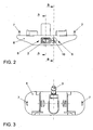
- zeigt eine Ansicht des Ausführungsbeispiels der Befeuchtungsvorrichtung in entgegengesetzter Richtung des Flüssigkeitsstrahls,
- Fig. 3
- zeigt eine Ansicht des Ausführungsbeispiels der Befeuchtungsvorrichtung von hinten,
- Fig. 4
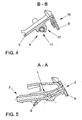
- zeigt einen Schnitt der Darstellung gemäß Fig. 2 entlang der Linie B-B,
- Fig. 5
- zeigt einen Schnitt der Ansicht gemäß Fig. 2 in Richtung der Linie A-A, und
- Fig. 6
- zeigt schematisch die Kombination des Ausführungsbeispiels der Befeuchtungsvorrichtung mit einem Karosserieteil eines Kraftfahrzeugs.
- Die Befeuchtungsvorrichtung besteht im Wesentlichen aus zwei Teilen, nämlich einem Düsenkörper 1 und einem Trägerelement 4. Dabei ist der Düsenkörper 1 so an dem Trägerelement 4 befestigt, dass er in einem kleinen Winkelbereich schwenkbar ist.
- Der Düsenkörper 1 ist ein Kunststoffteil, bei dem an einem Ende ein Flüssigkeitsanschluss 3, z.B. ein Anschlussstutzen, ausgebildet ist. An dem anderen Ende des Düsenkörpers 1 nimmt dieser eine Spritzdüse auf. Die Spritzdüse 2 kann in einem separaten Teil gebildet sein. Sie kann jedoch auch einstückig in dem Düsenkörper 1 ausgebildet sein. In dem Düsenkörper 1 erstreckt sich ein Flüssigkeitskanal von dem Anschluss 3 bis zur Austrittsöffnung der Spritzdüse 2. In Längsrichtung, etwa in der Mitte des Düsenkörpers 1, ist eine Befestigungseinrichtung vorgesehen, durch welche der Düsenkörper 1 in einer Halterung 17 des Trägerteils 4 um die Achse 11 schwenkbar befestigt werden kann. Die Halterung 17 für die schwenkbare Aufnahme des Düsenkörpers 1 ist etwa in der Mitte der Abdeckkappe ausgebildet.
- Das Trägerelement 4 besteht im Wesentlichen aus einer plattenförmigen Abdeckkappe 4 und einer Blende 6, die sich in einem Winkel α von der Abdeckkappe 5 weg erstreckt. Der α Winkel zwischen der Abdeckkappe 5 und der Blende 6 ist ein spitzer Winkel. Er ist vorzugsweise in einem Bereich zwischen 70° und 80°. Im vorliegenden Ausführungsbeispiel ist der Winkel α etwa 77°.
- In der Abdeckkappe 5 des Trägerelements 4 ist eine Aussparung, insbesondere eine Öffnung, zum Durchtritt des Düsenkörpers gebildet. Der Düsenkörper 1 ist so an dem Trägerelement 4 befestigt, dass sich der Flüssigkeitsanschluss 3 auf der einen Seite der Abdeckkappe 5 befindet, sich der Düsenkörper 1 von dem Flüssigkeitsanschluss 3 ausgehend durch die Aussparung oder Öffnung der Abdeckkappe 5 hindurch erstreckt und der Teil des Düsenkörpers 1, welcher die Spritzdüse 2 aufnimmt, auf der anderen Seite der Abdeckkappe 5 angeordnet ist.
- Die Blende 6 besitzt eine Öffnung 8, in welcher sich das vordere Ende des Düsenkörpers 1 bündig befindet. Bei diesem Ende des Düsenkörpers 1 ist die Spritzdüse 2 angeordnet, so dass ein Flüssigkeitsstrahl, der bei der Spritzdüse 2 austritt, durch die Öffnung 8 der Blende 6 auf die Scheibe eines Kraftfahrzeugs gespritzt werden kann.
- Die Blende 6 besitzt eine weitere Öffnung 9, in welcher eine Einstelleinrichtung 10 zum Einstellen des Schwenkwinkels des Düsenkörpers 1 angeordnet ist. Im vorliegenden Fall ist die Einstelleinrichtung 10 eine Schraube, die so mit dem Düsenkörper 1 und dem Trägerelement 4 gekoppelt ist, dass sich beim Drehen der Schraube der Winkel zwischen dem Düsenkörper 1 und dem Trägerelement 4 ändert. Damit ein solches Schwenken des Düsenkörpers 1 möglich ist, ist zwischen dem vorderen Ende des Düsenkörpers 1 und der Öffnung 8 der Blende 6 so viel Spiel vorgesehen, dass der Düsenkörper 1 um den gewünschten Winkelbereich verschwenkt werden kann.
- Fig. 6 zeigt die Kombination eines Karosserieteils eines Kraftfahrzeugs und der vorstehend mit Bezug zu den Fig. 1 bis 5 erläuterten Vorrichtung zum Befeuchten einer Scheibe des Kraftfahrzeugs. Die Motorraumhaube des Fahrzeugs besteht zumindest in dem Abschnitt, der benachbart zu der Windschutzscheibe ist, aus einem Außenblech 14, welches von außen sichtbar ist, und aus einem Innenblech 13, welches nur bei geöffneter Motorraumhaube sichtbar ist. Zwischen dem Außenblech 14 und dem Innenblech 13 ist ein Hohlraum 16 gebildet. Der Hohlraum 16 ist über eine Öffnung zugänglich, welche in dem Innenblech 13 gebildet ist. Durch diese Öffnung wird die Befeuchtungsvorrichtung so eingesetzt, dass die Öffnung gas- und blickdicht von der Abdeckkappe 5 des Trägerelements 4 der Befeuchtungsvorrichtung abgedeckt bzw. abgedichtet wird. Wenn die Befeuchtungsvorrichtung in die Öffnung des Innenblechs der Motorraumhaube eingesetzt ist, befindet sich der Teil des Düsenkörpers 1, bei welchem der Wasseranschluss 3 ausgebildet ist, innerhalb des Hohlraums 16 und der Teil des Düsenkörpers 1, welcher die Spritzdüse 2 aufnimmt, außerhalb des Hohlraums 16.
- In den Hohlraum 16 ist außerdem ein Wasserschlauch 12 eingeführt, welcher von einem Spritzwasserreservoir ausgeht. Bevor die Abdeckkappe 5 in der Öffnung des Innenblechs 13 befestigt wird, wird das Ende des Schlauches 12 über den Flüssigkeitsanschluss 3 des Düsenkörpers 1 gestülpt und an diesem befestigt. Die Öffnung in dem Innenblech 13 ist daher so groß, dass man mit den Fingern in den Hohlraum 16 hineingreifen kann, um das Ende des Schlauches 12 zu fassen. Nachdem der Schlauch an dem Düsenkörper 1 befestigt worden ist, wird die Abdeckkappe 5 mittels Vorsprüngen 7 (siehe Fig. 2 und 3) in die Öffnung des Innenblechs 13 eingeklippst. In den Hohlraum 16 können danach keine Gase aus dem Motorraum gelangen. Außerdem kann man bei geöffneter Motorraumhaube die Anschlüsse der Befeuchtungsvorrichtung nicht sehen.
- Unterhalb des Innenblechs 13 der Motorraumhaube ist ein weiteres Fahrzeugteil vorgesehen. Bei dem gezeigten Ausführungsbeispiel ist dies die Abdeckung 15 des Wasserkastens. Die Blende 6 des Trägerteils 4 der Befeuchtungsvorrichtung ist so ausgebildet, dass sie sich von dem Ende der Abdeckkappe 5 in Richtung der Wasserkastenabdeckung 15 erstreckt und unmittelbar vor dieser Abdeckung 15 endet. Die Blende 6 schließt somit die Lücke zwischen dem Innenblech 13 und der Wasserkastenabdeckung 15 ab. Blickt man aus der Richtung der Windschutzscheibe des Kraftfahrzeugs in den Bereich unter die vordere Kante der Motorraumhaube, ist nur der vordere Teil des Innenblechs 13, die Blende 6 und ein Teil der Wasserkastenabdeckung 15 zu sehen. Man kann aufgrund der Ausgestaltung der erfindungsgemäßen Befeuchtungsvorrichtung in Kombination mit den Karosserieteilen bzw. der Wasserkastenabdeckung 15 nicht weiter unter das Innenblech 13 der Motorraumhaube sehen. Außerdem können keine Fremdkörper durch diesen Spalt zwischen der Wasserkastenabdeckung 15 und der Motorraumhaube gelangen.
-
- 1.
- Düsenkörper
- 2
- Spritzdüse
- 3
- Flüssigkeitsanschluss
- 4
- Trägerelement
- 5
- Abdeckkappe
- 6
- Blende
- 7
- Befestigungsvorsprünge
- 8
- Öffnung für die Spritzdüse
- 9
- Öffnung für die Einstelleinrichtung
- 10
- Einstelleinrichtung
- 11
- Schwenkachse
- 12
- Schlauch
- 13
- Innenblech der Motorraumhaube
- 14
- Außenblech der Motorraumhaube
- 15
- Wasserkastenabdeckung
- 16
- Hohlraum
- 17
- Halterung des Trägerteils 4
Claims (8)
- Vorrichtung zum Befeuchten einer Scheibe eines Kraftfahrzeugs, wobei die Vorrichtung einen Düsenkörper (1), der eine Spritzdüse (2) aufnimmt und bei dem ein Flüssigkeitsanschluss (3) ausgebildet ist, und ein an einem Karosserieteil (13) befestigbares Trägerelement (4) aufweist, an dem der Düsenkörper (1) schwenkbar befestigt ist, wobei das Trägerelement (4) eine Abdeckkappe (5) aufweist und der Flüssigkeitsanschluss (3) auf einer Seite der Abdeckkappe (5) und die Spritzdüse (2) auf der anderen Seite der Abdeckkappe (5) angeordnet ist,
dadurch gekennzeichnet,
dass das Trägerelement (4) eine Blende (6) aufweist, die sich in einem Winkel (α) von der Abdeckkappe (5) weg erstreckt. - Vorrichtung nach Anspruch 1,
dadurch gekennzeichnet,
dass die Abdeckkappe (5) des Trägerelements (4) plattenförmig ist und eine Aussparung zum Durchtritt des Düsenkörpers (1) besitzt. - Vorrichtung nach Anspruch 1 oder 2,
dadurch gekennzeichnet,
dass die Blende (6) zumindest eine Öffnung (8) aufweist, die so angeordnet ist, dass ein aus der Spritzdüse (2) austretender Flüssigkeitsstrahl durch die Öffnung (8) durchtritt. - Vorrichtung nach einem der vorstehenden Ansprüche,
dadurch gekennzeichnet,
dass der Düsenkörper (1) eine Einstelleinrichtung (10) zum Einstellen des Schwenkwinkels des Düsenkörpers (1) aufweist, die durch die Öffnung der Blende (6) oder durch eine weitere Öffnung (9) in der Blende (6) betätigbar ist. - Vorrichtung nach Anspruch 3 oder 4,
dadurch gekennzeichnet,
dass sich an die Abdeckkappe (5) des Trägerteils (4) eine Halterung (17) zur schwenkbaren Aufnahme des Düsenkörpers (1) anschließt und dass das Ende des Düsenkörpers (1), bei dem die Spritzdüse (2) angeordnet ist, mit so viel Spiel von der Öffnung (9) der Blende (6) aufgenommen ist, dass der Düsenkörper (1) um einen bestimmten Schwenkwinkel zum Einstellen des Flüssigkeitsstrahlwinkels verschwenkt werden kann. - Kombination eines Karosserieteils (13, 14) eines Kraftfahrzeugs und einer Vorrichtung zum Befeuchten einer Scheibe des Kraftfahrzeugs nach einem der vorstehenden Ansprüche,
dadurch gekennzeichnet,
dass das Karosserieteil (13, 14) einen Hohlraum (16) mit einer Öffnung aufweist und dass die Abdeckkappe (5) des Trägerelements (4) der Befeuchtungsvorrichtung so auf die Öffnung des Hohlraums (16) aufgesetzt ist, dass sich der Flüssigkeitsanschluss (3) innerhalb des Hohlraums (16) befindet und die Spritzdüse (2) außerhalb des Hohlraums (16) befindet. - Kombination nach Anspruch 6,
dadurch gekennzeichnet,
dass das Karosserieteil (13, 14) eine Motorraumhaube des Kraftfahrzeugs ist und dass die Abdeckkappe (5) die Öffnung des Hohlraums (16) gasdicht abschließt. - Kombination nach Anspruch 7,
dadurch gekennzeichnet,
dass der Hohlraum (16) zwischen einem Außenblech (14) und einem Innenblech (13) der Motorraumhaube gebildet ist und dass die Öffnung des Hohlraums (16) in dem Innenblech (13) der Motorraumhaube ausgebildet ist.
Applications Claiming Priority (1)
| Application Number | Priority Date | Filing Date | Title |
|---|---|---|---|
| DE102005043080A DE102005043080A1 (de) | 2005-09-10 | 2005-09-10 | Vorrichtung zum Befeuchten einer Scheibe eines Kraftfahrzeugs und Kombination einer solchen mit einem Karosserieteil |
Publications (3)
| Publication Number | Publication Date |
|---|---|
| EP1762448A2 true EP1762448A2 (de) | 2007-03-14 |
| EP1762448A3 EP1762448A3 (de) | 2008-11-12 |
| EP1762448B1 EP1762448B1 (de) | 2011-05-11 |
Family
ID=37402657
Family Applications (1)
| Application Number | Title | Priority Date | Filing Date |
|---|---|---|---|
| EP06014990A Not-in-force EP1762448B1 (de) | 2005-09-10 | 2006-07-19 | Vorrichtung zum Befeuchten einer Scheibe eines Kraftfahrzeugs und Kombination einer solchen mit einem Karosserieteil |
Country Status (3)
| Country | Link |
|---|---|
| EP (1) | EP1762448B1 (de) |
| AT (1) | ATE508915T1 (de) |
| DE (1) | DE102005043080A1 (de) |
Citations (5)
| Publication number | Priority date | Publication date | Assignee | Title |
|---|---|---|---|---|
| DE1838995U (de) | 1959-03-10 | 1961-10-05 | Westfaelische Metall Ind K G H | Duesenkopf mit mindestens einer kugelfoermigen spritzduese fuer scheibenwaschanlagen an kraftfahrzeugen. |
| DE3925800A1 (de) | 1989-08-04 | 1991-02-07 | Bayerische Motoren Werke Ag | Scheibenwaschvorrichtung |
| DE4305245A1 (de) | 1993-02-20 | 1994-08-25 | Bayerische Motoren Werke Ag | Einstellbare Scheibenwaschvorrichtung |
| DE19641460A1 (de) | 1996-10-09 | 1998-04-30 | Volkswagen Ag | Vorrichtung zur Befeuchtung einer Scheibe eines Kraftfahrzeuges |
| DE19746059C2 (de) | 1997-10-17 | 2000-01-20 | Daimler Chrysler Ag | Scheibenwaschvorrichtung |
Family Cites Families (4)
| Publication number | Priority date | Publication date | Assignee | Title |
|---|---|---|---|---|
| DE19652083C2 (de) * | 1996-12-14 | 2002-07-11 | Siemens Ag | Zur Befestigung in einem Kraftfahrzeug vorgesehener Düsenstock |
| US6467701B2 (en) * | 1997-09-26 | 2002-10-22 | Mannesmann Vdo Ag | Shield cleaning system |
| JP3901873B2 (ja) * | 1999-05-27 | 2007-04-04 | 株式会社小糸製作所 | ヘッドランプクリーナ |
| DE10303410B4 (de) * | 2003-01-29 | 2013-10-31 | Volkswagen Ag | Kombination einer Scheibenwascheinrichtung mit einem Fahrzeugteil |
-
2005
- 2005-09-10 DE DE102005043080A patent/DE102005043080A1/de not_active Withdrawn
-
2006
- 2006-07-19 EP EP06014990A patent/EP1762448B1/de not_active Not-in-force
- 2006-07-19 AT AT06014990T patent/ATE508915T1/de active
Patent Citations (5)
| Publication number | Priority date | Publication date | Assignee | Title |
|---|---|---|---|---|
| DE1838995U (de) | 1959-03-10 | 1961-10-05 | Westfaelische Metall Ind K G H | Duesenkopf mit mindestens einer kugelfoermigen spritzduese fuer scheibenwaschanlagen an kraftfahrzeugen. |
| DE3925800A1 (de) | 1989-08-04 | 1991-02-07 | Bayerische Motoren Werke Ag | Scheibenwaschvorrichtung |
| DE4305245A1 (de) | 1993-02-20 | 1994-08-25 | Bayerische Motoren Werke Ag | Einstellbare Scheibenwaschvorrichtung |
| DE19641460A1 (de) | 1996-10-09 | 1998-04-30 | Volkswagen Ag | Vorrichtung zur Befeuchtung einer Scheibe eines Kraftfahrzeuges |
| DE19746059C2 (de) | 1997-10-17 | 2000-01-20 | Daimler Chrysler Ag | Scheibenwaschvorrichtung |
Also Published As
| Publication number | Publication date |
|---|---|
| EP1762448B1 (de) | 2011-05-11 |
| EP1762448A3 (de) | 2008-11-12 |
| DE102005043080A1 (de) | 2007-03-15 |
| ATE508915T1 (de) | 2011-05-15 |
Similar Documents
| Publication | Publication Date | Title |
|---|---|---|
| DE102007060252B4 (de) | Wischerblatt und Fahrzeugwischer | |
| DE102006050721A1 (de) | Wischerblatt und Fahrzeugwischereinrichtung | |
| EP0028370A1 (de) | Kraftfahrzeug mit einem den toten Winkel erfassenden Zusatzspiegel | |
| DE69836997T2 (de) | Konstruktion eines öffnungsfähigen Fahrzeugdaches | |
| DE2813909A1 (de) | Instrumententafel fuer kraftfahrzeuge | |
| DE4338685C1 (de) | Fahrzeugkarosserie | |
| DE3002134C2 (de) | ||
| DE102016012099A1 (de) | Scheibenwischer und Fahrzeug mit Scheibenwischer | |
| EP1549535B1 (de) | Waschvorrichtung für eine fahrzeugscheibe | |
| DE3908612A1 (de) | Belueftungsduese fuer fahrzeuginnenraeume | |
| DE102010005812A1 (de) | Instrumententafel eines Kraftfahrzeuges mit einem Ablagefach | |
| EP1978259B1 (de) | Schalldämpfer zur Verwendung an einem Kompressor | |
| EP1762448B1 (de) | Vorrichtung zum Befeuchten einer Scheibe eines Kraftfahrzeugs und Kombination einer solchen mit einem Karosserieteil | |
| DE102006031713B4 (de) | Düse einer Scheibenwaschanlage | |
| DE3818666A1 (de) | Luftkanal fuer ein kraftfahrzeug | |
| DE3512312A1 (de) | Windabweiseranordnung | |
| DE4034851A1 (de) | Vorrichtung zur geraeusch- und schwingungsminderung an schiebedachoeffnungen von kraftfahrzeugen | |
| DE19502793A1 (de) | Mehrzweck-Windschutzvorrichtung für Kraftfahrzeuge | |
| DE102005045410A1 (de) | Scheibenwischeranlage für ein Fahrzeug mit wenigstens einer waschflüssigkeitsführenden Wischerwelle | |
| DE10217490B4 (de) | Kraftfahrzeug mit wenigstens einer Bremsleuchte in einem oberen Heckscheiben-Randbereich | |
| DE102019001000A1 (de) | Belüftungseinheit eines Heizungs-, Lüftungs- und Klimatisierungssystems | |
| DE19858585B4 (de) | Vorrichtung zum Belüften eines Kraftfahrzeug-Fensters | |
| EP2125453B1 (de) | Gehäuseanordnung einer wischeranlage eines kraftfahrzeugs | |
| DE2823528C2 (de) | Belüftungssystem für den Fahrgastraum eines Kraftfahrzeuges | |
| DE10011840B4 (de) | Scheibenwascheinrichtung für eine Kraftfahrzeugfrontscheibe |
Legal Events
| Date | Code | Title | Description |
|---|---|---|---|
| PUAI | Public reference made under article 153(3) epc to a published international application that has entered the european phase |
Free format text: ORIGINAL CODE: 0009012 |
|
| AK | Designated contracting states |
Kind code of ref document: A2 Designated state(s): AT BE BG CH CY CZ DE DK EE ES FI FR GB GR HU IE IS IT LI LT LU LV MC NL PL PT RO SE SI SK TR |
|
| AX | Request for extension of the european patent |
Extension state: AL BA HR MK YU |
|
| PUAL | Search report despatched |
Free format text: ORIGINAL CODE: 0009013 |
|
| AK | Designated contracting states |
Kind code of ref document: A3 Designated state(s): AT BE BG CH CY CZ DE DK EE ES FI FR GB GR HU IE IS IT LI LT LU LV MC NL PL PT RO SE SI SK TR |
|
| AX | Request for extension of the european patent |
Extension state: AL BA HR MK RS |
|
| 17P | Request for examination filed |
Effective date: 20090512 |
|
| AKX | Designation fees paid |
Designated state(s): AT BE BG CH CY CZ DE DK EE ES FI FR GB GR HU IE IS IT LI LT LU LV MC NL PL PT RO SE SI SK TR |
|
| 17Q | First examination report despatched |
Effective date: 20100119 |
|
| GRAP | Despatch of communication of intention to grant a patent |
Free format text: ORIGINAL CODE: EPIDOSNIGR1 |
|
| GRAS | Grant fee paid |
Free format text: ORIGINAL CODE: EPIDOSNIGR3 |
|
| GRAA | (expected) grant |
Free format text: ORIGINAL CODE: 0009210 |
|
| AK | Designated contracting states |
Kind code of ref document: B1 Designated state(s): AT BE BG CH CY CZ DE DK EE ES FI FR GB GR HU IE IS IT LI LT LU LV MC NL PL PT RO SE SI SK TR |
|
| REG | Reference to a national code |
Ref country code: GB Ref legal event code: FG4D Free format text: NOT ENGLISH |
|
| REG | Reference to a national code |
Ref country code: CH Ref legal event code: EP |
|
| REG | Reference to a national code |
Ref country code: IE Ref legal event code: FG4D |
|
| REG | Reference to a national code |
Ref country code: DE Ref legal event code: R096 Ref document number: 502006009465 Country of ref document: DE Effective date: 20110622 |
|
| REG | Reference to a national code |
Ref country code: NL Ref legal event code: VDEP Effective date: 20110511 |
|
| PG25 | Lapsed in a contracting state [announced via postgrant information from national office to epo] |
Ref country code: LT Free format text: LAPSE BECAUSE OF FAILURE TO SUBMIT A TRANSLATION OF THE DESCRIPTION OR TO PAY THE FEE WITHIN THE PRESCRIBED TIME-LIMIT Effective date: 20110511 Ref country code: SE Free format text: LAPSE BECAUSE OF FAILURE TO SUBMIT A TRANSLATION OF THE DESCRIPTION OR TO PAY THE FEE WITHIN THE PRESCRIBED TIME-LIMIT Effective date: 20110511 Ref country code: PT Free format text: LAPSE BECAUSE OF FAILURE TO SUBMIT A TRANSLATION OF THE DESCRIPTION OR TO PAY THE FEE WITHIN THE PRESCRIBED TIME-LIMIT Effective date: 20110912 |
|
| PG25 | Lapsed in a contracting state [announced via postgrant information from national office to epo] |
Ref country code: IS Free format text: LAPSE BECAUSE OF FAILURE TO SUBMIT A TRANSLATION OF THE DESCRIPTION OR TO PAY THE FEE WITHIN THE PRESCRIBED TIME-LIMIT Effective date: 20110911 Ref country code: SI Free format text: LAPSE BECAUSE OF FAILURE TO SUBMIT A TRANSLATION OF THE DESCRIPTION OR TO PAY THE FEE WITHIN THE PRESCRIBED TIME-LIMIT Effective date: 20110511 Ref country code: ES Free format text: LAPSE BECAUSE OF FAILURE TO SUBMIT A TRANSLATION OF THE DESCRIPTION OR TO PAY THE FEE WITHIN THE PRESCRIBED TIME-LIMIT Effective date: 20110822 Ref country code: CY Free format text: LAPSE BECAUSE OF FAILURE TO SUBMIT A TRANSLATION OF THE DESCRIPTION OR TO PAY THE FEE WITHIN THE PRESCRIBED TIME-LIMIT Effective date: 20110511 Ref country code: GR Free format text: LAPSE BECAUSE OF FAILURE TO SUBMIT A TRANSLATION OF THE DESCRIPTION OR TO PAY THE FEE WITHIN THE PRESCRIBED TIME-LIMIT Effective date: 20110812 Ref country code: FI Free format text: LAPSE BECAUSE OF FAILURE TO SUBMIT A TRANSLATION OF THE DESCRIPTION OR TO PAY THE FEE WITHIN THE PRESCRIBED TIME-LIMIT Effective date: 20110511 Ref country code: LV Free format text: LAPSE BECAUSE OF FAILURE TO SUBMIT A TRANSLATION OF THE DESCRIPTION OR TO PAY THE FEE WITHIN THE PRESCRIBED TIME-LIMIT Effective date: 20110511 |
|
| REG | Reference to a national code |
Ref country code: IE Ref legal event code: FD4D |
|
| PG25 | Lapsed in a contracting state [announced via postgrant information from national office to epo] |
Ref country code: NL Free format text: LAPSE BECAUSE OF FAILURE TO SUBMIT A TRANSLATION OF THE DESCRIPTION OR TO PAY THE FEE WITHIN THE PRESCRIBED TIME-LIMIT Effective date: 20110511 |
|
| BERE | Be: lapsed |
Owner name: VOLKSWAGEN A.G. Effective date: 20110731 |
|
| PG25 | Lapsed in a contracting state [announced via postgrant information from national office to epo] |
Ref country code: IE Free format text: LAPSE BECAUSE OF FAILURE TO SUBMIT A TRANSLATION OF THE DESCRIPTION OR TO PAY THE FEE WITHIN THE PRESCRIBED TIME-LIMIT Effective date: 20110511 Ref country code: EE Free format text: LAPSE BECAUSE OF FAILURE TO SUBMIT A TRANSLATION OF THE DESCRIPTION OR TO PAY THE FEE WITHIN THE PRESCRIBED TIME-LIMIT Effective date: 20110511 Ref country code: CZ Free format text: LAPSE BECAUSE OF FAILURE TO SUBMIT A TRANSLATION OF THE DESCRIPTION OR TO PAY THE FEE WITHIN THE PRESCRIBED TIME-LIMIT Effective date: 20110511 |
|
| PG25 | Lapsed in a contracting state [announced via postgrant information from national office to epo] |
Ref country code: SK Free format text: LAPSE BECAUSE OF FAILURE TO SUBMIT A TRANSLATION OF THE DESCRIPTION OR TO PAY THE FEE WITHIN THE PRESCRIBED TIME-LIMIT Effective date: 20110511 Ref country code: MC Free format text: LAPSE BECAUSE OF NON-PAYMENT OF DUE FEES Effective date: 20110731 Ref country code: PL Free format text: LAPSE BECAUSE OF FAILURE TO SUBMIT A TRANSLATION OF THE DESCRIPTION OR TO PAY THE FEE WITHIN THE PRESCRIBED TIME-LIMIT Effective date: 20110511 Ref country code: RO Free format text: LAPSE BECAUSE OF FAILURE TO SUBMIT A TRANSLATION OF THE DESCRIPTION OR TO PAY THE FEE WITHIN THE PRESCRIBED TIME-LIMIT Effective date: 20110511 Ref country code: DK Free format text: LAPSE BECAUSE OF FAILURE TO SUBMIT A TRANSLATION OF THE DESCRIPTION OR TO PAY THE FEE WITHIN THE PRESCRIBED TIME-LIMIT Effective date: 20110511 |
|
| REG | Reference to a national code |
Ref country code: CH Ref legal event code: PL |
|
| PLBE | No opposition filed within time limit |
Free format text: ORIGINAL CODE: 0009261 |
|
| STAA | Information on the status of an ep patent application or granted ep patent |
Free format text: STATUS: NO OPPOSITION FILED WITHIN TIME LIMIT |
|
| 26N | No opposition filed |
Effective date: 20120214 |
|
| GBPC | Gb: european patent ceased through non-payment of renewal fee |
Effective date: 20110811 |
|
| PG25 | Lapsed in a contracting state [announced via postgrant information from national office to epo] |
Ref country code: LI Free format text: LAPSE BECAUSE OF NON-PAYMENT OF DUE FEES Effective date: 20110731 Ref country code: CH Free format text: LAPSE BECAUSE OF NON-PAYMENT OF DUE FEES Effective date: 20110731 Ref country code: BE Free format text: LAPSE BECAUSE OF NON-PAYMENT OF DUE FEES Effective date: 20110731 |
|
| PG25 | Lapsed in a contracting state [announced via postgrant information from national office to epo] |
Ref country code: IT Free format text: LAPSE BECAUSE OF FAILURE TO SUBMIT A TRANSLATION OF THE DESCRIPTION OR TO PAY THE FEE WITHIN THE PRESCRIBED TIME-LIMIT Effective date: 20110511 |
|
| REG | Reference to a national code |
Ref country code: DE Ref legal event code: R097 Ref document number: 502006009465 Country of ref document: DE Effective date: 20120214 |
|
| PG25 | Lapsed in a contracting state [announced via postgrant information from national office to epo] |
Ref country code: GB Free format text: LAPSE BECAUSE OF NON-PAYMENT OF DUE FEES Effective date: 20110811 |
|
| REG | Reference to a national code |
Ref country code: AT Ref legal event code: MM01 Ref document number: 508915 Country of ref document: AT Kind code of ref document: T Effective date: 20110719 |
|
| PG25 | Lapsed in a contracting state [announced via postgrant information from national office to epo] |
Ref country code: AT Free format text: LAPSE BECAUSE OF NON-PAYMENT OF DUE FEES Effective date: 20110719 |
|
| REG | Reference to a national code |
Ref country code: DE Ref legal event code: R084 Ref document number: 502006009465 Country of ref document: DE Effective date: 20130316 |
|
| PG25 | Lapsed in a contracting state [announced via postgrant information from national office to epo] |
Ref country code: LU Free format text: LAPSE BECAUSE OF NON-PAYMENT OF DUE FEES Effective date: 20110719 |
|
| PG25 | Lapsed in a contracting state [announced via postgrant information from national office to epo] |
Ref country code: BG Free format text: LAPSE BECAUSE OF FAILURE TO SUBMIT A TRANSLATION OF THE DESCRIPTION OR TO PAY THE FEE WITHIN THE PRESCRIBED TIME-LIMIT Effective date: 20110811 |
|
| PG25 | Lapsed in a contracting state [announced via postgrant information from national office to epo] |
Ref country code: TR Free format text: LAPSE BECAUSE OF FAILURE TO SUBMIT A TRANSLATION OF THE DESCRIPTION OR TO PAY THE FEE WITHIN THE PRESCRIBED TIME-LIMIT Effective date: 20110511 |
|
| PG25 | Lapsed in a contracting state [announced via postgrant information from national office to epo] |
Ref country code: HU Free format text: LAPSE BECAUSE OF FAILURE TO SUBMIT A TRANSLATION OF THE DESCRIPTION OR TO PAY THE FEE WITHIN THE PRESCRIBED TIME-LIMIT Effective date: 20110511 |
|
| REG | Reference to a national code |
Ref country code: FR Ref legal event code: PLFP Year of fee payment: 10 |
|
| REG | Reference to a national code |
Ref country code: FR Ref legal event code: PLFP Year of fee payment: 11 |
|
| REG | Reference to a national code |
Ref country code: FR Ref legal event code: PLFP Year of fee payment: 12 |
|
| REG | Reference to a national code |
Ref country code: FR Ref legal event code: PLFP Year of fee payment: 13 |
|
| P01 | Opt-out of the competence of the unified patent court (upc) registered |
Effective date: 20230523 |
|
| PGFP | Annual fee paid to national office [announced via postgrant information from national office to epo] |
Ref country code: DE Payment date: 20240731 Year of fee payment: 19 |
|
| PGFP | Annual fee paid to national office [announced via postgrant information from national office to epo] |
Ref country code: FR Payment date: 20240725 Year of fee payment: 19 |
|
| REG | Reference to a national code |
Ref country code: DE Ref legal event code: R119 Ref document number: 502006009465 Country of ref document: DE |
|
| PG25 | Lapsed in a contracting state [announced via postgrant information from national office to epo] |
Ref country code: DE Free format text: LAPSE BECAUSE OF NON-PAYMENT OF DUE FEES Effective date: 20260203 |
|
| PG25 | Lapsed in a contracting state [announced via postgrant information from national office to epo] |
Ref country code: FR Free format text: LAPSE BECAUSE OF NON-PAYMENT OF DUE FEES Effective date: 20250731 |