EP1760920B1 - Lautsprecher-gruppeneinrichtung und verfahren zum setzen eines schallstrahls einer lautsprechergruppeneinrichtung - Google Patents
Lautsprecher-gruppeneinrichtung und verfahren zum setzen eines schallstrahls einer lautsprechergruppeneinrichtung Download PDFInfo
- Publication number
- EP1760920B1 EP1760920B1 EP05753349.9A EP05753349A EP1760920B1 EP 1760920 B1 EP1760920 B1 EP 1760920B1 EP 05753349 A EP05753349 A EP 05753349A EP 1760920 B1 EP1760920 B1 EP 1760920B1
- Authority
- EP
- European Patent Office
- Prior art keywords
- sound
- speaker array
- audio
- output
- peaks
- Prior art date
- Legal status (The legal status is an assumption and is not a legal conclusion. Google has not performed a legal analysis and makes no representation as to the accuracy of the status listed.)
- Ceased
Links
Images





Classifications
-
- H—ELECTRICITY
- H04—ELECTRIC COMMUNICATION TECHNIQUE
- H04R—LOUDSPEAKERS, MICROPHONES, GRAMOPHONE PICK-UPS OR LIKE ACOUSTIC ELECTROMECHANICAL TRANSDUCERS; ELECTRIC HEARING AIDS; PUBLIC ADDRESS SYSTEMS
- H04R1/00—Details of transducers, loudspeakers or microphones
- H04R1/20—Arrangements for obtaining desired frequency or directional characteristics
- H04R1/32—Arrangements for obtaining desired frequency or directional characteristics for obtaining desired directional characteristic only
- H04R1/40—Arrangements for obtaining desired frequency or directional characteristics for obtaining desired directional characteristic only by combining a number of identical transducers
- H04R1/403—Arrangements for obtaining desired frequency or directional characteristics for obtaining desired directional characteristic only by combining a number of identical transducers loud-speakers
-
- H—ELECTRICITY
- H04—ELECTRIC COMMUNICATION TECHNIQUE
- H04R—LOUDSPEAKERS, MICROPHONES, GRAMOPHONE PICK-UPS OR LIKE ACOUSTIC ELECTROMECHANICAL TRANSDUCERS; ELECTRIC HEARING AIDS; PUBLIC ADDRESS SYSTEMS
- H04R3/00—Circuits for transducers
- H04R3/12—Circuits for transducers for distributing signals to two or more loudspeakers
-
- H—ELECTRICITY
- H04—ELECTRIC COMMUNICATION TECHNIQUE
- H04S—STEREOPHONIC SYSTEMS
- H04S7/00—Indicating arrangements; Control arrangements, e.g. balance control
- H04S7/30—Control circuits for electronic adaptation of the sound field
- H04S7/301—Automatic calibration of stereophonic sound system, e.g. with test microphone
-
- H—ELECTRICITY
- H04—ELECTRIC COMMUNICATION TECHNIQUE
- H04R—LOUDSPEAKERS, MICROPHONES, GRAMOPHONE PICK-UPS OR LIKE ACOUSTIC ELECTROMECHANICAL TRANSDUCERS; ELECTRIC HEARING AIDS; PUBLIC ADDRESS SYSTEMS
- H04R2201/00—Details of transducers, loudspeakers or microphones covered by H04R1/00 but not provided for in any of its subgroups
- H04R2201/40—Details of arrangements for obtaining desired directional characteristic by combining a number of identical transducers covered by H04R1/40 but not provided for in any of its subgroups
- H04R2201/401—2D or 3D arrays of transducers
-
- H—ELECTRICITY
- H04—ELECTRIC COMMUNICATION TECHNIQUE
- H04R—LOUDSPEAKERS, MICROPHONES, GRAMOPHONE PICK-UPS OR LIKE ACOUSTIC ELECTROMECHANICAL TRANSDUCERS; ELECTRIC HEARING AIDS; PUBLIC ADDRESS SYSTEMS
- H04R2203/00—Details of circuits for transducers, loudspeakers or microphones covered by H04R3/00 but not provided for in any of its subgroups
- H04R2203/12—Beamforming aspects for stereophonic sound reproduction with loudspeaker arrays
-
- H—ELECTRICITY
- H04—ELECTRIC COMMUNICATION TECHNIQUE
- H04R—LOUDSPEAKERS, MICROPHONES, GRAMOPHONE PICK-UPS OR LIKE ACOUSTIC ELECTROMECHANICAL TRANSDUCERS; ELECTRIC HEARING AIDS; PUBLIC ADDRESS SYSTEMS
- H04R2205/00—Details of stereophonic arrangements covered by H04R5/00 but not provided for in any of its subgroups
- H04R2205/022—Plurality of transducers corresponding to a plurality of sound channels in each earpiece of headphones or in a single enclosure
Definitions
- the present invention relates to a speaker array apparatus for outputting a plurality of audio beams to reproduce a surround-sound, and particularly relates to a speaker array apparatus having a high degree of freedom as to an installation location thereof so that the audio beams can be set easily.
- Fig. 12 is a top perspective view of a room where a speaker apparatus disclosed in JP-T-2003-510924 is installed.
- Fig. 12 shows an example of a speaker apparatus with a speaker array constituting a 5.1 ch surround-sound system.
- a front left channel L(Left)ch a front right channel R(Right)ch, a center channel C(Center)ch, a rear left channel SL(Surround Left)ch, a rear right channel SR(Surround Right)ch, and a subwoofer LFE(Low Frequency Effects)ch.
- a speaker apparatus 213 shown in Fig. 12 has several hundreds of speaker units disposed in a predetermined array in one panel.
- the speaker apparatus 213 adjusts the timing when a surround-sound is output from each speaker unit in each channel, so as to emit the surround-sound like beams.
- the speaker apparatus 213 delays and controls the audio beams so that the audio beams have a focus on a desired point in the space.
- the sound of each channel is reflected by the ceiling or wall so as to create a sound source toward the wall.
- a multi-channel sound field is reproduced. As shown in Fig.
- the speaker apparatus 213 disposed under a video apparatus 222 installed near a central portion of a room wall 220 and in front of a user U outputs sounds like a center speaker (C) and a bass compensating subwoofer (LEF) directly to the user.
- the speaker apparatus 213 makes walls 221 and 222 on the left and right sides of the user U reflect audio beams so as to create a virtual Rch speaker 214 and a virtual Lch speaker 215.
- the speaker apparatus 213 makes the walls 221 and 222 on the left and right sides of the user and a wall 223 at the rear of the user U reflect audio beams so as to create a virtual SRch speaker 216 and a virtual SLch speaker 217 on the rear left and right sides of the user U.
- audio signals from respective channels are delayed and controlled to be formed into beams, and these sounds formed into the beams are reflected by the walls so as to create a plurality of sound sources.
- a sense of surround-sound can be obtained as if a plurality of speakers were installed around the user U.
- the background-art speaker array apparatus When the background-art speaker array apparatus is installed, information about the listening position of the user and the width, depth and height of the room as information about the shape of the installation environment are given to the speaker array apparatus. Thus, angles of audio beams are automatically calculated so that the audio beams are set.
- a specialist adjusts the angles of audio beams manually while listening to a reproduced sound from the speaker array apparatus in the listening position.
- Reflective or resonant surfaces may be used to achieve a surround sound effect
- a microphone may be located in front of an array of loudspeakers
- beams of light may be used to identify the present focal position
- a limiting device may be used to ensure that clipping or distortion is reduced when more than one input signal is output by the same device and the concept of beam directivity may be used to achieve input nulls or beams in a microphone made up of an array of input transducers.
- sound field shaping information may be associated with an audio signal to be broadcast.
- US 2003/185404 A1 discloses an array of speakers which are fed from a single source of audio frequency sound but each speaker transmits the sound delayed by an amount which is determined by the distance between a particular speaker and a selected region in space, so that sound from each speaker constructively adds at the selected region in space.
- a sufficiently large number of speakers are employed so that when sound reaches a region in space at the same moment in time the audio volume will be increased substantially over sound in regions where there is not constructive interference.
- This simple technique allows audio frequency sound to be heard in only selected regions within the room or other auditory space. Multiple regions with multiple soundtracks can be created by simultaneously playing variously delayed soundtracks over each of the speakers in the array.
- a speaker array apparatus is provided as set forth in claim 1.
- the speaker array apparatus includes a signal processing portion for distributing an audio signal input from the outside to all or a part of the speakers of the speaker array, and controlling the output timings when sounds are output from these speakers, so that audio beams are output from the speaker array.
- the positions of the walls of the room where the audio beams output from the array speaker should be reflected so that a multi-channel audio signal can be reproduced optimally can be detected easily in a short time.
- sweep angles with which the peaks were detected are set as angles with which audio beams should be output in respective channels of the multi-channel audio signal.
- a direct sound output from the speaker array toward the listening position is set as an audio beam of a center channel of a multi-channel surround-sound regardless of the shape of the room where the speaker array apparatus is installed.
- the signal level of this direct sound is higher than that of an audio beam reflected by a wall.
- the direct sound is the highest in signal level. Therefore, if the highest peak is selected from the signal level of the test audio signal stored in the storage portion, a peak to be set as the output angle of the center channel can be detected easily.
- the output angle of the audio beam of the center channel is determined, left and right with respect to the user can be determined. Thus, based on this output angle, output angles of the other channels can be set easily.
- the beam output angle of the center channel of the multi-channel surround-sound is shifted from a direction perpendicular to the front surface of the speaker array by an angle not smaller than a predetermined angle.
- the surround-sound will be off balance.
- at least the information portion gives the user information to prompt the user to change the listening position or to prompt the user to change the sound reproduction method. Accordingly, in the aforementioned case, settings can be changed so that the surround-sound can be reproduced in a balanced manner.
- the beam setting portion forms a signal localization of one of the channels as a phantom using audio beams directed in a plurality of directions so as to form a symmetric sound field.
- the listener does not recognize these signals as individual, but recognizes them as one audio signal coming from this phantom.
- the phantom is adjusted to be formed in a position symmetric with a signal of the other channel, the surround-sound can be reproduced in a balanced manner.
- the speaker array outputs audio beams based on a test audio signal having no periodicity and no correlation and limited to a band where beams can be formed.
- the speaker array apparatus outputs sounds limited to a band where beams can be formed by the speaker array, and having no periodicity and no correlation as if they were noise. Accordingly, the audio beams can be turned within a desired range. Even if an audio beam which has not been reflected overlaps an audio beam which has been reflected by a wall or the like, there is no fear that there occurs interference, but it is possible to collect test sounds surely.
- a method for setting audio beams in a speaker array apparatus is provided as set forth in claim 7.
- a sweep angle of a peak where the signal level of the test sound is the highest is set as a beam output angle of a center channel of the multi-channel surround-sound.
- the method for setting audio beams further includes the step of providing at least information to prompt the user to change the listening position or to prompt the user to change a sound reproduction method when the beam output angle of the center channel of the multi-channel surround-sound set by the beam setting portion is shifted from a direction perpendicular to a front surface of the speaker array by an angle greater than or equal to a predetermined angle.
- a signal localization of one of the channels is formed as a phantom using audio beams directed in a plurality of directions so as to form a symmetric sound field.
- the signal level of the test sound is modulated with an envelope having a maximum at the center of a sweep range of the audio beams.
- Audio beams based on a test audio signal having no periodicity and no correlation and limited to a band where beams can be formed are output in the audio beam output step.
- a microphone When the speaker array apparatus according to the present invention is installed in a room, a microphone is placed in a listening position of a user, and a test sound is output from a speaker array so as to turn (sweep) audio beams automatically. In this event, the audio beams are collected by the microphone.
- sounds output from the speaker array directly to the microphone or sounds reflected from walls of the room to the microphone can be detected as peaks of the signal level.
- the positions of the walls of the room where the audio beams output from the array speaker should be reflected so that a multi-channel audio signal can be reproduced optimally can be detected easily in a short time.
- the user can easily perform setting to reproduce the multi-channel surround-sound after the installation of the speaker array apparatus regardless of the shape of the room where the speaker array apparatus is installed, the layout of furniture, or the like.
- Fig. 1 is a block diagram showing the schematic configuration of a speaker array apparatus according to an embodiment of the present invention.
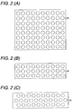
- Figs. 2 are views of layouts of speaker arrays, in which (A) shows the case where speakers are arrayed in a matrix, (B) shows the case where speakers are arrayed in three lines, and (C) shows the case where speakers are arrayed in three lines so that the speakers in the second line are displaced from the speakers in the first line and the speakers in the third line.
- A shows the case where speakers are arrayed in a matrix
- B shows the case where speakers are arrayed in three lines
- C shows the case where speakers are arrayed in three lines so that the speakers in the second line are displaced from the speakers in the first line and the speakers in the third line.
- the following description will be made about an example of a speaker array apparatus serving for a 5.1 ch surround-sound system.
- an audio signal of the LFEch has little directivity, but the audio signal is output from the speaker array apparatus directly to the user. Therefore, description about the processing of the audio signal of the LFEch will be omitted in the following description.
- the speaker array apparatus 1 has a microphone 2, an A/D converter 3, a system control portion 4, a storage portion 5, an operating portion 6, a display portion 7, a phantom formation portion 8, a beam formation portion 9, and a speaker array 10.
- the speaker array apparatus 1 has an Lch terminal, an Rch terminal, an SLch terminal, an SRch terminal and a Cch terminal as external input terminals of 5.1 ch surround-sound audio signals.
- the phantom formation portion 8 has Lch amplifiers 21a and 21b, Rch amplifiers 22a and 22b, SLch amplifiers 23a, 23b and 23c, SRch amplifiers 24a, 24b and 24c, an Lch adder 25, an Rch adder 26 and a Cch adder 27.
- the beam formation portion 9 has a delay portion 31 for performing delay processing upon five audio signals output from the phantom formation portion 8 individually, power amplifiers 32-1 to 32-5 for amplifying the five audio signals output from the delay portion 31, and an adder 33 for adding signals output from the power amplifiers 32-1 to 32-5 respectively.
- the beam formation portion 9 consists of n blocks, and the speaker array 10 consists of n speakers 30, so that the speakers 30 are connected to the outputs of the beam formation portion 9 respectively.
- the portion of the speaker array apparatus 1 excluding the microphone 2 will be referred to as a body 1 h.
- the microphone 2 is a non-directional microphone, which is connected to the A/D converter 3.
- the A/D converter 3 converts (samples) an analog audio signal collected by the microphone 2, into a digital audio signal, and outputs the digital audio signal to the system control portion 4.
- the system control portion 4 has a user I/F processing portion 11, a beam control processing portion 12, a measured data analysis processing portion 13, and a sound source position correction processing portion 14.
- the beam control processing portion 12 When an audio beam setting mode is carried out for setting the angles with which audio beams of the respective channels should be output, for example, when the speaker array apparatus 1 is installed, the beam control processing portion 12 outputs a test audio signal to the beam formation portion 9 so as to sweep (turn) audio beams of a test sound output from the speaker array 10.
- the measured data analysis processing portion 13 makes the storage portion 5 store the test audio signal output from the speaker array 10 and collected by the microphone 2 when the audio beam setting mode is carried out.
- the measured data analysis processing portion 13 reads the audio signal stored in the storage portion 5 and detects peaks in the audio signal. Based on the peaks, the measured data analysis processing portion 13 sets the angles with which sounds of the respective channels Cch, Lch, Rch, SLch and SRch should be output.
- the measured data analysis processing portion 13 outputs the results to the beam control processing portion 12.
- the beam control processing portion 12 Based on the analysis results output from the measured data analysis processing portion 13, the beam control processing portion 12 outputs angle setting signals to the beam formation portion 9.
- the angle setting signals will be used for setting the angles of the channels respectively.
- the measured data analysis processing 13 outputs a signal to the sound source position correction processing portion 14 when the angle balance among the channels is not good.
- the sound source position correction processing portion 14 outputs a sound source position correction signal to the phantom formation portion 8 based on the signal received from the measured data analysis processing portion 13.
- the storage portion 5 stores digital audio signals output from the A/D converter 3 through the system control portion 4.
- the operating portion 6 accepts inputs of various settings from the user and outputs a signal to the system control portion 4 in accordance with the inputs.
- the speaker array 10 has a plurality ( n ) of speakers 30 disposed in a predetermined array of a matrix, lines or the like on one panel.
- the speaker array 10 adjusts the timing when a surround-sound is output from each speaker in each channel, so as to emit the surround-sound like beams.
- the speaker array 10 delays and controls the audio beams so that the audio beams have a focus in a desired position on the wall surface or the like.
- the sounds of the respective channels are reflected by the walls of the room where the speaker array apparatus 1 is installed, so that a sound source is created at a desired point.
- a multi-channel sound field is formed to reproduce the surround-sound.
- FIGs. 3 are top views of the room where the speaker array apparatus is installed.
- Figs. 3 are views for explaining the operation of the speaker array apparatus sweeping the audio beams and the operation of the microphone collecting the audio beams.
- description will be made about the case that a room 40 where the speaker array apparatus 1 is installed is a rectangular parallelepiped having an ideal shape, and the body 1h of the speaker array apparatus 1 is placed near the center of a front wall 41 of the room 40, in order to make the present invention understood easily.
- the audio beams are reflected by a left wall 42, the rear wall 43 and a right wall 44 of the room 40 in accordance with the sweep angle ⁇ of the audio beams output from the speaker array 10.
- direct sounds of the audio beams and indirect sounds of the audio beams reflected by the respective walls are collected by the microphone 2, and optimized angles with which the audio beams should be output are obtained.
- the audio beams output from the speaker array 10 in the audio beam setting mode are set by the system control portion 4 so as to have no correlation but to output audio signals whose beam angles are limited to a controllable range though the beam angles should depend on the shape of the speaker array apparatus 1 and the layout of the respective speakers of the speaker array 10.
- Acoustic waves having no periodicity for example, around 4 kHz, or acoustic waves such as noise having no periodicity are suitable as test audio signals.
- the audio beams can be turned within a predetermined range.
- the elevation angles (depression angles) of the audio beams output from the front surface of the speaker array 10 can be set at desired angles in accordance with the position and height where the speaker array apparatus 1 is installed.
- the speaker array apparatus 1 may be designed in such a manner that the elevation angles (depression angles) are changed whenever sweeping of the audio beams is performed over the range of from 0 degree to 180 degrees, so that the audio beams are output all over the room.
- an optimum acoustic field can be formed, for example, when a virtual speaker can be formed in an optimum position by the audio beams reflected by the ceiling and the rear wall.
- the output angle of the Cch audio beam is set at 90°.
- the detectivity (S/N ratio) of each surround-sound channel having a long beam path can be increased. Further, an optimum angle can be set easily for an audio beam of each channel.
- the focal length of the sweep signal is set so that the beam diameter is the narrowest in the listening position of the user in each sweep angle. That is, as shown in Fig. 4(B) , setting may be done so that the focal length with which the beam diameter is the narrowest varies in a parabola having a peak at 90°. Thus, it is possible to improve the angular sensitivity of the beams in the microphone position.
- the system control portion 4 selects and detects how many peaks beyond the threshold value of the gain are present in areas on the opposite sides (temporally in front and behind and angularly left and right) with respect to the peak set as Cch, excluding peaks too close to the peak 57 set as Cch or peaks corresponding to angles which are impossible as the installation angles of virtual speakers based on common sense.
- the system control portion 4 assigns the peaks to the surround-sound channel and the front channel in order of increasing distance from the peak 57 set as Cch, and calculates the angles corresponding to the peaks.
- the system control portion 4 of the speaker array apparatus 1 sets stereophonic reproduction with two peaks close to the center peak as the surround-sound channels and with a direct sound as the front channel.
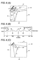
- the speaker array apparatus 1 outputs, to the user U, the Cch, Lch and Rch sounds as direct sounds, the SLch sound as a reflected sound reflected once by the rear wall 63, and the SRch sound as a reflected sound reflected once by the right wall 64, as shown in Fig. 6(C) .
- the user U can enjoy listening the ideal surround-sound in the listening position.
- Figs. 7 are diagrams for explaining the operation for installing the speaker array apparatus: (A) is a top view showing the operation for measuring audio beams when the speaker array apparatus is installed near the center of the front wall but in a different position from that in Figs. 5 in a room having a rectangular parallelepiped shape; and (B) is a graph showing measured data.
- the system control portion 4 selects and detects how many peaks beyond the threshold value of the gain are present in areas on the opposite sides with respect to the peak 71 set as Cch, excluding peaks too close to the peak set as Cch or peaks corresponding to angles which are impossible as the installation angles of virtual speakers based on common sense.
- the listening position is widely displaced from the front of the speaker array 10.
- the speaker array apparatus 1 makes the display portion 7 display an instruction to select a setting mode to stereophonically reproduce all the channels or to reproduce Lch and Rch as stereophonic sounds and reproduce SLch and SRch as surround-sounds.
- the speaker array apparatus 1 When an audio sound or the like is input from the outside, the speaker array apparatus 1 outputs, to the user U, the Cch, Lch and Rch sounds as direct sounds, the SLch sound as a reflected sound reflected once by the left wall 77, and the SRch sound as a reflected sound reflected once by the left wall 81, as shown in Fig. 8(C) .
- the user U can reproduce surround-sound properly even in the room 75 whose shape is not ideal.
- Figs. 9 are graphs showing examples of data collected in the audio beam setting mode by the speaker array apparatus.
- the room where the speaker array apparatus 1 is installed is not ideal. Even if the room has an ideal shape, there may be a case where the number of peaks higher than the threshold value is larger or smaller than the required number of channels in some layout of furniture.
- the audio beam setting mode is carried out to sweep audio beams, with the result that data shown in Fig. 9(A) are obtained.
- the system control portion 4 of the speaker array apparatus 1 selects a peak value whose gain level is the highest of peaks located within a valid range as described above. In the data shown in Fig.
- the gain level of a peak 96 is the highest, but the waveform thereof is pulsed and has a width not larger than a constant value. Such a waveform is impossible as an audio beam. Thus, the peak 96 is excluded as noise.
- the system control portion 4 sets a peak 94 having the highest gain level apart from the peak 96, as the angle with which the Cch audio beam should be output. Subsequently, the system control portion 4 selects and detects how many peaks beyond the threshold value of the gain are present in areas on the opposite sides with respect to the peak set as Cch. In this event, peaks 93 and 95 too close to the peak 94 set as Cch are excluded because the beam may overlap the user so that the localization can be set at the speaker direction.
- the difference in angle between the peak 103 and a peak 101 is substantially equal to that between the peak 103 and a peak 106
- the difference in angle between the peak 103 and a peak 102 is substantially equal to that between the peak 103 and a peak 104. Therefore, a peak 105 is excluded, and the peak 101, the peak 102, the peak 104 and the peak 106 are set as the output angles of the Lch, SLch, SRch and Rch audio beams respectively.
- peaks located within a valid range are selected.
- Adjacent peaks 113 and 115 on both sides of the peak 114 set as Cch are valid peaks, and correspond to substantially symmetric angles with respect to the peak 114. Accordingly, the peak 113 and the peak 115 are set as the angles with which SLch and SRch should be output, respectively, by the system control portion 4.
- the system control portion 4 can do setting so that peaks located within a valid range and having as large a distance from the peaks assigned to the rear surround-sounds as possible are assigned to the front channels.
- peaks 112 and 116 are not used, but a peak 111 is set as the output angle of Lch, and a peak 117 is set as the output angle of Rch.
- the difference in angle between the peak 123 and a peak 121 is substantially equal to that between the peak 123 and a peak 124. Therefore, a peak 122 is excluded, and the peak 121 and the peak 124 are set as the output angles of SLch and Rch respectively. Lch and Rch are set to be reproduced as stereo sounds.
- the system control portion 4 of the speaker array apparatus 1 sets a peak 126, which is a peak having the highest gain level of peaks located within a valid range, as the output angle of Cch. Subsequently, the system control portion 4 selects and detects how many peaks beyond the threshold value of the gain are present in areas on the opposite sides with respect to the peak set as Cch. In the case of the data shown in Fig. 9(E) , one peak is on one side with respect to the peak 123 set as Cch, while no peak is on the other side. Therefore, there is no symmetry. For that reason, the system control portion 4 sets Lch and Rch as direct sounds so as to reproduce them as stereophonic sounds, or sets Cch as a direct sound so as to reproduce it as a monaural sound.
- FIGs. 10 are diagrams for explaining the operation for installing the speaker array apparatus: (A) is a top view showing the operation for measuring audio beams when the speaker array apparatus is installed near the left of the front wall of a room having a rectangular parallelepiped shape; (B) is a graph showing measured data; and (C) is a top view of the rectangular parallelepiped room after the speaker array apparatus has been installed.
- the user places the microphone 2 in a listening position of surround-sound, and sets the audio beam setting mode to collect audio data.
- the system control portion 4 sets a sweep angle of a peak 137, which has the highest gain level of peaks located within a valid range, as the output angle of Cch.
- the system control portion 4 selects and detects how many peaks beyond the threshold value of the gain are present in areas on the opposite sides with respect to the peak set as Cch.
- the system control portion 4 determines whether each peak 135, 136, 138, 139 other than the peak 137 set as Cch has a valid angle or not, and whether the peaks are symmetric or not.
- ⁇ front and ⁇ surround are values larger than the predetermined threshold value. Therefore, the system control portion 4 performs processing for forming a phantom sound source.
- the system control portion 4 of the speaker array apparatus 1 is designed so that the phantom sound source is formed in a position symmetrical to, of audio beams reaching the listener, an audio beam having a smaller angle with respect to an audio beam set as Cch.
- a phantom sound source is formed in accordance with a smaller angle of an angle ⁇ 11 between the peak 135 corresponding to Lch and the peak 137 set as Cch and an angle ⁇ 12 between the peak 139 corresponding to Rch and the peak 137 set as Cch. That is, the system control portion 4 compares the angle c between the peak 137 set as Cch and the peak 135 with the angle d between the peak 137 and the peak 139 based on the data shown in Fig. 10(B) , and selects the smaller angle ⁇ c.
- a phantom sound source is formed in accordance with a smaller angle of an angle ⁇ 13 between the peak 136 corresponding to SLch and the peak 137 set as Cch and an angle ⁇ 14 between the peak 138 corresponding to SRch and the peak 137 set as Cch. That is, the system control portion 4 compares the angle a between the peak 137 set as Cch and the peak 136 adjacent thereto with the angle ⁇ b between the peak 137 and the peak 138 based on the data shown in Fig. 10(B) , and selects the larger angle ⁇ b.
- the system control portion 4 outputs a sound source position correction signal to the phantom formation portion 8 so as to form a phantom sound source for Lch out of Cch and Lch and form a phantom sound source for Rch out of Cch and Rch.
- the system control portion 4 outputs a sound source position correction signal to the phantom formation portion 8 so as to form a phantom sound source for SLch out of Lch and SLch and form a phantom sound source for SRch out of Rch and SRch.
- the system control portion 4 outputs a sound source position correction signal to the phantom formation portion 8 so as to form a phantom sound source for SLch out of Cch and SLch and form a phantom sound source for SRch out of Cch and SRch.
- the system control portion 4 forms Lch and Rch as surround-sounds out of the audio beams 135 and 138, and forms phantoms 140 and 141 for SLch and SRch as shown in Fig. 10(C) .
- the listening position of the user is not in the center of the room 130 but asymmetric, the user can enjoy listening surround-sound reproduced properly.
- the speaker array apparatus 1 After automatic control for performing setting thus, the speaker array apparatus 1 prompts the user U to confirm the setting through a test tone. If there is no problem, optimum surround-sound can be further provided to the user U by automatic adjustment sequences such as level adjustment of each channel, frequency characteristic adjustment, time alignment adjustment, etc.
- Fig. 11 is a flow chart for explaining the operation with which the speaker array apparatus carries out the audio beam setting mode.
- the user U installs the body 1h of the speaker array apparatus 1 in a desired position of the room, and places the microphone 2 in the listening position.
- the user U operates the operating portion 6 of the body 1h to input the installation position (in a corner or along a wall) of the speaker array apparatus 1 in the room, and then starts the audio beam setting mode.
- the system control portion 4 of the speaker array apparatus 1 detects the input for starting the audio beam setting mode after the input of the installation position of the speaker array apparatus 1 due to the operation of the operating portion 6 (s1), the system control portion 4 forms a sweep signal and outputs the sweep signal to the beam formation portion 9.
- a beam signal formed by the beam formation portion 9 is supplied to the speaker array 10 so as to sweep the range from the 0-degree direction to the 180-degree direction with the sweep signal.
- Sounds reflected by the walls of the room and direct sounds output from the speaker array 10 are collected by the microphone 2.
- the collected sound data are converted into digital audio signals by the A/D converter 3, and accumulated in the storage 5 (s2).
- Step s4 the system control portion 4 checks, selects and detects how many peaks (side peaks) beyond the threshold value of the gain are present in areas on the opposite sides (temporally in front and behind and angularly left and right) with respect to the peak set as Cch, excluding peaks too close to the peak set as Cch or peaks corresponding to angles which are impossible as the installation angles of virtual speakers based on common sense. In this event, symmetry of the side peaks with respect to Cch is examined (s6).
- Step s8 When the installation position of the speaker array apparatus 1 is a corner in the room in Step s8 (s8), and when one peak is present on each of the opposite sides with respect to the Cch in Step s9, the peaks are assigned to the surround-sounds so as to reproduce the surround-sounds as audio beams, while the front sounds are set for stereophonic reproduction (s12). Then, processing of Step s13 is performed.
- the system control portion 4 determines whether the difference in angle between the beam sound channels assigned to the surround-sounds is larger than a threshold value or not (s14). When the difference in angle is larger than the threshold value, the system control portion 4 performs angle correction and performs processing for forming a phantom sound source (s15). When Step s15 is terminated or when the difference in angle is not larger than the threshold value in Step s14, the system control portion 4 makes the display portion 7 display contents to prompt the user to perform checking to confirm the settings of the surround-sounds, and waits for an input from the operating portion 6 (s17).
- setting of audio beams which has been difficult in a background-art speaker array apparatus can be performed easily and quickly.
- the setting is superior in affinity to automatic level, quality and distance correction techniques.
- a series of audio beam settings can be performed by automatic measuring.
- a microphone When a speaker array apparatus according to the present invention is installed in a room, a microphone is placed in a position where a user will listen, and a test sound is output from a speaker array so that audio beams are automatically turned (swept). In this event, the audio beams are collected by the microphone so that sounds output from the speaker array directly to the microphone and sounds reflected from walls of the room to the microphone can be detected as peaks of a signal level.
- the positions of the walls of the room where the audio beams output from the array speaker should be reflected so that a multi-channel audio signal can be reproduced optimally can be detected easily in a short time.
Landscapes
- Physics & Mathematics (AREA)
- Engineering & Computer Science (AREA)
- Acoustics & Sound (AREA)
- Signal Processing (AREA)
- Health & Medical Sciences (AREA)
- Otolaryngology (AREA)
- General Health & Medical Sciences (AREA)
- Stereophonic System (AREA)
- Circuit For Audible Band Transducer (AREA)
- Obtaining Desirable Characteristics In Audible-Bandwidth Transducers (AREA)
Claims (12)
- Lautsprechergruppenvorrichtung (1), die Folgendes aufweist:eine Lautsprecher-Array bzw. -Gruppe (10), die eine Vielzahl von Lautsprechern (30) zum Ausgeben von Audiostrahlen (34a, 34b, 34c, 34d) basierend auf einem Testaudiosignal aufweist;einen Testklangschwenkteil, der die Audiostrahlen (34a, 34b, 34c, 34d) schwenkt;ein Mikrofon (2), das in einer Abhörposition angeordnet wird und einen Testklang auffängt, und zwar einschließlich indirekter Klänge und reflektierter Klänge der Audiostrahlen (34a, 34b, 34c, 34d), die von der Lautsprechergruppe (10) ausgegeben werden;einen Speicherteil (5), der einen Signalpegel des Testklangs speichert, der durch das Mikrofon (2) aufgefangen wird, und die Winkel schwenkt, wenn die Audiostrahlen (34a, 34b, 34c, 34d) zugehörig zu den Testklängen von der Lautsprechergruppe (10) ausgegeben werden;einen Auswahlteil, der eine Vielzahl von Spitzen (55-59; 65-69; 70-74; 82-86; 91-97; 101-106; 111-117; 135-139) des Signalpegels auswählt, und zwar basierend auf dem Signalpegel des Testklangs, der in dem Speicherteil gespeichert ist; undeinen Strahleinstellungsteil, der die Schwenkwinkel der ausgewählten Vielzahl von Spitzen (55-59; 65-69; 70-74; 82-86; 91-97; 101-106; 111-117; 135-139) als Strahlausgabewinkel einstellt, die Winkel zur jeweiligen Ausgabe von Audiostrahlen der Kanäle eines Multikanal-Raumklangs bzw. -Surround-Sounds sind;dadurch gekennzeichnet, dassder Strahleinstellungsteil einen Schwenkwinkel einer Spitze (57, 67, 71, 84, 94, 103, 114, 137), in der der Signalpegel des Testklangs der höchste ist, als einen Strahlenausgabewinkel eines mittleren Kanals (C) des Mehrkanal-Surround-Sounds einstellt; undwenn die Ausgabewinkel für die entsprechenden Kanäle asymmetrisch in Bezug auf den Strahlausgabewinkel des mittleren Kanals (C) sind, der Strahleinstellungsteil eine Signallokalisierung von einem der Kanäle als ein Phantom unter Verwendung von Audiostrahlen (34a, 34b, 34c, 34d) bildet, die in eine Vielzahl von Richtungen gerichtet sind, um ein symmetrisches Klangfeld zu bilden.
- Lautsprechergruppenvorrichtung gemäß Anspruch 1, wobei wenn die Anzahl der Spitzen (55-59; 65-69; 70-74; 82-86; 91-97; 101-106; 111-117; 135-139), die aus dem Signalpegel des Testklangs ausgewählt werden, der in dem Speicherteil (5) gespeichert ist, kleiner als die Anzahl der Kanäle des Mehrkanal-Surround-Sounds ist, der Strahleinstellungsteil die Schwenkwinkel der ausgewählten Spitzen als Strahlausgabewinkel von einem oder mehreren Kanälen des Mehrkanal-Surround-Sounds einstellt, und die Klänge der anderen Kanäle als der Kanäle für die Klangausgabewinkel eingestellt werden, als direkte Klänge einstellt, die ausgegeben werden, um direkt zu der Hörposition übertragen zu werden.
- Lautsprechergruppenvorrichtung gemäß Anspruch 1, die ferner einen Informationsteil aufweist, der zumindest Information vorsieht, um einen Benutzer (U) zu veranlassen, die Hörposition zu wechseln, oder um den Benutzer (U) zu veranlassen, ein Klangreproduktionsverfahren zu verändern, wenn der Strahlausgabewinkel des mittleren Kanals (C) des Mehrkanal-Surround-Sounds, der durch den Strahleinstellungsteil eingestellt wird, von einer Richtung, die senkrecht zu einer vorderen Oberfläche der Lautsprechergruppe (10) um einen Winkel, der größer oder gleich einem vorbestimmten Winkel ist, versetzt ist.
- Lautsprechergruppenvorrichtung gemäß Anspruch 1, die ferner einen Eingabeteil aufweist, der eine Eingabe der Installationspositionsinformation eines Körpers (1h) der Lautsprechergruppenvorrichtung (1) aufnimmt;
wobei der Strahleinstellungsteil eine Vielzahl von Spitzen (55-59; 65-69; 70-74; 82-86; 91-97; 101-106; 111-117; 135-139) aus dem Signalpegel des Testklangs auswählt, der in dem Speicherteil (5) gespeichert ist, und zwar basierend auf der Installationspositionsinformation des Körpers (1h). - Lautsprechergruppenvorrichtung gemäß Anspruch 1, wobei der Testklangschwenkteil den Signalpegel des Testklangs mit einer Umhüllung bzw. Hüllkurve moduliert, die ein Maximum bei der Mitte des Schwenkbereichs der Audiostrahlen (34a, 34b, 34c, 34d) aufweist.
- Lautsprechergruppenvorrichtung gemäß Anspruch 1, wobei die Lautsprechergruppe (10) Audiostrahlen (34a, 34b, 34c, 34d) basierend auf einem Testaudiosignal ausgibt, das keine Periodizität und keine Korrelation aufweist und auf ein Band beschränkt ist, in dem Strahlen gebildet werden können.
- Verfahren zum Einstellen von Audiostrahlen (34a, 34b, 34c, 34d) in einer Lautsprechergruppenvorrichtung (1), das Folgendes aufweist:Ausgeben von Audiostrahlen (34a, 34b, 34c, 34d) basierend auf einem Testaudiosignal von einer Lautsprechergruppe (10) mit einer Vielzahl von Lautsprechern (30);Schwenken der Audiostrahlen (34a, 34b, 34c, 34d);Auffangen, in einer Abhör- bzw. Hörposition eines Testklangs, der direkte Klänge und reflektierte Klänge der Audiostrahlen (34a, 34b, 34c, 34d) aufweist, die von der Lautsprechergruppe (10) ausgegeben werden;Speichern von Signalpegeln des Testklangs, der in dem Klangauffangschritt aufgefangen wird, und von Schwenkwinkeln, wenn die Audiostrahlen (34a, 34b, 34c, 34d) zugehörig zu den Testklängen von der Lautsprechergruppe (10) ausgegeben werden, um die Signalpegel mit den Schwenkwinkeln zu assoziieren;Auswählen einer Vielzahl von Spitzen (55-59; 65-69; 70-74; 82-86; 91-97; 101-106; 111-117; 135-139) des Signalpegels basierend auf dem gespeicherten Signalpegel des Testklangs; undEinstellen von Schwenkwinkeln der Vielzahl von Spitzen (55-59; 65-69; 70-74; 82-86; 91-97; 101-106; 111-117; 135-139), die in dem Auswahlschritt ausgewählt werden, als Klangausgabewinkel, die Winkel sind, mit denen die Klangstrahlen der Kanäle eines Mehrkanal-Surround-Sounds ausgeben werden sollen;dadurch gekennzeichnet, dassin dem Strahleinstellungsschritt ein Schwenkwinkel einer Spitze (57, 67, 71, 84, 94, 103, 114, 137), wo der Signalpegel des Testklangs am höchsten ist, als ein Strahlausgabewinkel eines mittleren Kanals (C) des Mehrkanal-Surround-Sounds eingestellt wird; undin dem Strahleinstellungsschritt, wenn die Ausgabewinkel, die für die entsprechenden Kanäle eingestellt werden, asymmetrisch in Bezug auf die Strahlausgabewinkel des mittleren Kanals (C) sind, eine Signallokalisierung von einem der Kanäle als ein Phantom gebildet wird, das Audiostrahlen verwendet, die in eine Vielzahl von Richtung gerichtet sind, um ein symmetrisches Klangfeld zu bilden.
- Verfahren zum Einstellen von Klangstrahlen gemäß Anspruch 7, wobei in dem Strahleinstellungsschritt, wenn die Anzahl der Spitzen (55-59; 65-69; 70-74; 82-86; 91-97; 101-106; 111-117; 135-139), die aus dem gespeicherten Signalpegel des Testklangs ausgewählt wird, kleiner als die Anzahl der Kanäle des Mehrkanal-Surround-Sounds ist, die Schwenkwinkel der ausgewählten Spitzen als Strahlausgabewinkel von einem oder mehreren Kanälen des Mehrkanal-Surround-Sounds eingestellt werden, während Klänge der anderen Kanäle als den Kanälen, für die die Strahlausgabewinkel eingestellt werden, als direkte Klänge eingestellt werden, die ausgegeben werden sollen, um direkt zu der Hörposition weitergeleitet zu werden.
- Verfahren zum Einstellen von Audiostrahlen gemäß Anspruch 7, das ferner den Prozess des Vorsehens von zumindest Information zum Veranlassen eines Nutzers (U), die Hörposition zu verändern, oder zum Veranlassen des Nutzers (U) ein Klangreproduktionsverfahren zu verändern, aufweist, wenn der Strahlausgabewinkel des mittleren Kanals (C) des Mehrkanal-Surround-Sounds, der durch den Strahleinstellungsschritt eingestellt wird, von einer Richtung senkrecht zu einer vorderen Oberfläche der Lautsprechergruppe (10) um einen Winkel, der größer oder gleich einem vorbestimmten Winkel ist, versetzt ist.
- Verfahren zum Einstellen von Audiostrahlen gemäß Anspruch 7, das ferner den Prozess des Aufnehmens einer Eingabe der Installationspositionsinformation eines Körpers (1h) der Lautsprechergruppenanordnung (1) aufweist, wobei in dem Strahleinstellungsschritt eine Vielzahl von Spitzen (55-59; 65-69; 70-74; 82-86; 91-97; 101-106; 111-117; 135-139) aus dem Signalpegel des Testklangs ausgewählt werden, der in dem Speicherteil (5) gespeichert ist, und zwar basierend auf der Installationspositionsinformation des Körpers (1h).
- Verfahren zum Einstellen von Audiostrahlen gemäß Anspruch 7, wobei in dem Testklangschwenkschritt der Signalpegel des Testklangs mit einer Umhüllung bzw. Hüllkurve mit einem Maximum bei der Mitte eines Schwenkbereichs der Audiostrahlen (34a, 34b, 34c, 34d) moduliert wird.
- Verfahren zum Einstellen von Audiostrahlen gemäß Anspruch 7, wobei Audiostrahlen (34a, 34b, 34c, 34d) basierend auf einem Testaudiosignal, das keine Periodizität und keine Korrelation aufweist und auf ein Band beschränkt ist, in dem Strahlen gebildet werden können, in dem Audiostrahlausgabeschritt ausgegeben werden.
Applications Claiming Priority (2)
| Application Number | Priority Date | Filing Date | Title |
|---|---|---|---|
| JP2004185364A JP4127248B2 (ja) | 2004-06-23 | 2004-06-23 | スピーカアレイ装置及びスピーカアレイ装置の音声ビーム設定方法 |
| PCT/JP2005/011345 WO2006001272A1 (ja) | 2004-06-23 | 2005-06-21 | スピーカアレイ装置及びスピーカアレイ装置の音声ビーム設定方法 |
Publications (3)
| Publication Number | Publication Date |
|---|---|
| EP1760920A1 EP1760920A1 (de) | 2007-03-07 |
| EP1760920A4 EP1760920A4 (de) | 2009-12-30 |
| EP1760920B1 true EP1760920B1 (de) | 2018-03-21 |
Family
ID=35780444
Family Applications (1)
| Application Number | Title | Priority Date | Filing Date |
|---|---|---|---|
| EP05753349.9A Ceased EP1760920B1 (de) | 2004-06-23 | 2005-06-21 | Lautsprecher-gruppeneinrichtung und verfahren zum setzen eines schallstrahls einer lautsprechergruppeneinrichtung |
Country Status (5)
| Country | Link |
|---|---|
| US (2) | US7889878B2 (de) |
| EP (1) | EP1760920B1 (de) |
| JP (1) | JP4127248B2 (de) |
| CN (1) | CN1973465B (de) |
| WO (1) | WO2006001272A1 (de) |
Families Citing this family (86)
| Publication number | Priority date | Publication date | Assignee | Title |
|---|---|---|---|---|
| JP4107300B2 (ja) | 2005-03-10 | 2008-06-25 | ヤマハ株式会社 | サラウンドシステム |
| JP4949638B2 (ja) * | 2005-04-14 | 2012-06-13 | ヤマハ株式会社 | オーディオ信号供給装置 |
| JP2007259088A (ja) * | 2006-03-23 | 2007-10-04 | Yamaha Corp | スピーカ装置およびオーディオシステム |
| JP2009141385A (ja) * | 2006-03-30 | 2009-06-25 | Pioneer Electronic Corp | 音場制御方法、音場制御装置、集音装置、スピーカ装置及び音場制御用プログラム |
| WO2008013125A1 (en) | 2006-07-25 | 2008-01-31 | Nec Corporation | Semiconductor device and method for manufacturing same |
| JP4345784B2 (ja) * | 2006-08-21 | 2009-10-14 | ソニー株式会社 | 音響収音装置及び音響収音方法 |
| KR101365988B1 (ko) * | 2007-01-05 | 2014-02-21 | 삼성전자주식회사 | 지향성 스피커 시스템의 자동 셋-업 방법 및 장치 |
| KR101297300B1 (ko) | 2007-01-31 | 2013-08-16 | 삼성전자주식회사 | 스피커 어레이를 이용한 프론트 서라운드 재생 시스템 및그 신호 재생 방법 |
| JP4449998B2 (ja) | 2007-03-12 | 2010-04-14 | ヤマハ株式会社 | アレイスピーカ装置 |
| US8483395B2 (en) * | 2007-05-04 | 2013-07-09 | Electronics And Telecommunications Research Institute | Sound field reproduction apparatus and method for reproducing reflections |
| JP4561785B2 (ja) | 2007-07-03 | 2010-10-13 | ヤマハ株式会社 | スピーカアレイ装置 |
| JP4488036B2 (ja) | 2007-07-23 | 2010-06-23 | ヤマハ株式会社 | スピーカアレイ装置 |
| JP2009044359A (ja) * | 2007-08-08 | 2009-02-26 | Sony Corp | 衝立、制御装置および方法、プログラム、並びに記録媒体 |
| KR101292206B1 (ko) * | 2007-10-01 | 2013-08-01 | 삼성전자주식회사 | 어레이 스피커 시스템 및 그 구현 방법 |
| GB0721313D0 (en) * | 2007-10-31 | 2007-12-12 | 1 Ltd | Microphone based auto set-up |
| JP4609502B2 (ja) * | 2008-02-27 | 2011-01-12 | ヤマハ株式会社 | サラウンド出力装置およびプログラム |
| JP5156934B2 (ja) * | 2008-03-07 | 2013-03-06 | 学校法人日本大学 | 音響測定装置 |
| US8588431B2 (en) * | 2008-04-21 | 2013-11-19 | Snap Networks, Inc. | Electrical system for a speaker and its control |
| JP5316189B2 (ja) * | 2008-05-23 | 2013-10-16 | ヤマハ株式会社 | Avシステム |
| JP5211882B2 (ja) * | 2008-06-19 | 2013-06-12 | ヤマハ株式会社 | 放音システム |
| JP5141390B2 (ja) * | 2008-06-19 | 2013-02-13 | ヤマハ株式会社 | スピーカ装置およびスピーカシステム |
| US8274611B2 (en) * | 2008-06-27 | 2012-09-25 | Mitsubishi Electric Visual Solutions America, Inc. | System and methods for television with integrated sound projection system |
| WO2010013301A1 (ja) * | 2008-07-28 | 2010-02-04 | パイオニア株式会社 | コンテンツ再生装置及び方法 |
| KR101334964B1 (ko) * | 2008-12-12 | 2013-11-29 | 삼성전자주식회사 | 사운드 처리 장치 및 방법 |
| KR101295848B1 (ko) * | 2008-12-17 | 2013-08-12 | 삼성전자주식회사 | 어레이스피커 시스템에서 음향을 포커싱하는 장치 및 방법 |
| JP5577597B2 (ja) | 2009-01-28 | 2014-08-27 | ヤマハ株式会社 | スピーカアレイ装置、信号処理方法およびプログラム |
| JP5293291B2 (ja) | 2009-03-11 | 2013-09-18 | ヤマハ株式会社 | スピーカアレイ装置 |
| KR101613683B1 (ko) | 2009-10-20 | 2016-04-20 | 삼성전자주식회사 | 음향 방사 패턴 생성 장치 및 방법 |
| US8542854B2 (en) * | 2010-03-04 | 2013-09-24 | Logitech Europe, S.A. | Virtual surround for loudspeakers with increased constant directivity |
| US9264813B2 (en) * | 2010-03-04 | 2016-02-16 | Logitech, Europe S.A. | Virtual surround for loudspeakers with increased constant directivity |
| KR101753065B1 (ko) | 2010-09-02 | 2017-07-03 | 삼성전자주식회사 | 공간 음향 에너지 분포 조절 방법 및 장치 |
| TWI486068B (zh) * | 2010-09-13 | 2015-05-21 | Htc Corp | 行動電子裝置與其聲音播放方法 |
| JP5821172B2 (ja) * | 2010-09-14 | 2015-11-24 | ヤマハ株式会社 | スピーカ装置 |
| KR20120053587A (ko) * | 2010-11-18 | 2012-05-29 | 삼성전자주식회사 | 디스플레이장치 및 그 사운드 제어방법 |
| CN103167375A (zh) * | 2011-12-13 | 2013-06-19 | 新昌有限公司 | 人脸辨识喇叭装置及其声音指向调整方法 |
| US20130204629A1 (en) * | 2012-02-08 | 2013-08-08 | Panasonic Corporation | Voice input device and display device |
| JP5966738B2 (ja) * | 2012-08-01 | 2016-08-10 | ヤマハ株式会社 | 放音装置 |
| JP6003409B2 (ja) * | 2012-08-30 | 2016-10-05 | ヤマハ株式会社 | 放音装置および音響ビームの放音方向の調整方法 |
| US9794718B2 (en) * | 2012-08-31 | 2017-10-17 | Dolby Laboratories Licensing Corporation | Reflected sound rendering for object-based audio |
| KR101892643B1 (ko) * | 2013-03-05 | 2018-08-29 | 애플 인크. | 하나 이상의 청취자들의 위치에 기초한 스피커 어레이의 빔 패턴의 조정 |
| US9967437B1 (en) * | 2013-03-06 | 2018-05-08 | Amazon Technologies, Inc. | Dynamic audio synchronization |
| US9743201B1 (en) * | 2013-03-14 | 2017-08-22 | Apple Inc. | Loudspeaker array protection management |
| JP6405628B2 (ja) * | 2013-12-26 | 2018-10-17 | ヤマハ株式会社 | スピーカ装置 |
| CN104641659B (zh) | 2013-08-19 | 2017-12-05 | 雅马哈株式会社 | 扬声器设备和音频信号处理方法 |
| US9257113B2 (en) * | 2013-08-27 | 2016-02-09 | Texas Instruments Incorporated | Method and system for active noise cancellation |
| CN105096999B (zh) * | 2014-04-30 | 2018-01-23 | 华为技术有限公司 | 一种音频播放方法和音频播放设备 |
| WO2016004258A1 (en) | 2014-07-03 | 2016-01-07 | Gopro, Inc. | Automatic generation of video and directional audio from spherical content |
| JP2016019086A (ja) * | 2014-07-07 | 2016-02-01 | ヤマハ株式会社 | ビーム方向設定装置およびビーム方向設定システム |
| KR102197230B1 (ko) | 2014-10-06 | 2020-12-31 | 한국전자통신연구원 | 음향 특성을 예측하는 오디오 시스템 및 방법 |
| JP6414459B2 (ja) | 2014-12-18 | 2018-10-31 | ヤマハ株式会社 | スピーカアレイ装置 |
| US20160294484A1 (en) * | 2015-03-31 | 2016-10-06 | Qualcomm Technologies International, Ltd. | Embedding codes in an audio signal |
| KR102340202B1 (ko) | 2015-06-25 | 2021-12-17 | 한국전자통신연구원 | 실내의 반사 특성을 추출하는 오디오 시스템 및 방법 |
| US10033928B1 (en) | 2015-10-29 | 2018-07-24 | Gopro, Inc. | Apparatus and methods for rolling shutter compensation for multi-camera systems |
| US9973696B1 (en) | 2015-11-23 | 2018-05-15 | Gopro, Inc. | Apparatus and methods for image alignment |
| US9792709B1 (en) | 2015-11-23 | 2017-10-17 | Gopro, Inc. | Apparatus and methods for image alignment |
| US9848132B2 (en) | 2015-11-24 | 2017-12-19 | Gopro, Inc. | Multi-camera time synchronization |
| US9602795B1 (en) | 2016-02-22 | 2017-03-21 | Gopro, Inc. | System and method for presenting and viewing a spherical video segment |
| US9743060B1 (en) | 2016-02-22 | 2017-08-22 | Gopro, Inc. | System and method for presenting and viewing a spherical video segment |
| US9973746B2 (en) | 2016-02-17 | 2018-05-15 | Gopro, Inc. | System and method for presenting and viewing a spherical video segment |
| US9922398B1 (en) | 2016-06-30 | 2018-03-20 | Gopro, Inc. | Systems and methods for generating stabilized visual content using spherical visual content |
| KR20180033771A (ko) * | 2016-09-26 | 2018-04-04 | 엘지전자 주식회사 | 영상표시장치 |
| US9934758B1 (en) | 2016-09-21 | 2018-04-03 | Gopro, Inc. | Systems and methods for simulating adaptation of eyes to changes in lighting conditions |
| US10268896B1 (en) | 2016-10-05 | 2019-04-23 | Gopro, Inc. | Systems and methods for determining video highlight based on conveyance positions of video content capture |
| US10043552B1 (en) | 2016-10-08 | 2018-08-07 | Gopro, Inc. | Systems and methods for providing thumbnails for video content |
| US10684679B1 (en) | 2016-10-21 | 2020-06-16 | Gopro, Inc. | Systems and methods for generating viewpoints for visual content based on gaze |
| US10194101B1 (en) | 2017-02-22 | 2019-01-29 | Gopro, Inc. | Systems and methods for rolling shutter compensation using iterative process |
| CN106872944B (zh) * | 2017-02-27 | 2020-05-05 | 海尔优家智能科技(北京)有限公司 | 一种基于麦克风阵列的声源定位方法及装置 |
| US10349199B2 (en) | 2017-04-28 | 2019-07-09 | Bose Corporation | Acoustic array systems |
| US10469973B2 (en) | 2017-04-28 | 2019-11-05 | Bose Corporation | Speaker array systems |
| US10531196B2 (en) * | 2017-06-02 | 2020-01-07 | Apple Inc. | Spatially ducking audio produced through a beamforming loudspeaker array |
| US10469818B1 (en) | 2017-07-11 | 2019-11-05 | Gopro, Inc. | Systems and methods for facilitating consumption of video content |
| CN107424593B (zh) * | 2017-08-25 | 2021-04-13 | 广州丰谱信息技术有限公司 | 一种区域划动触控式曲面立体扬声器阵列的数码乐器 |
| CN107741113A (zh) * | 2017-10-13 | 2018-02-27 | 青岛海尔股份有限公司 | 一种智能语音模块及冰箱的测试方法 |
| CN108513243B (zh) * | 2018-02-28 | 2020-12-08 | 成都星环科技有限公司 | 一种智能声场校准系统 |
| US10587807B2 (en) | 2018-05-18 | 2020-03-10 | Gopro, Inc. | Systems and methods for stabilizing videos |
| US10440473B1 (en) * | 2018-06-22 | 2019-10-08 | EVA Automation, Inc. | Automatic de-baffling |
| US10432864B1 (en) | 2018-09-19 | 2019-10-01 | Gopro, Inc. | Systems and methods for stabilizing videos |
| US10397727B1 (en) * | 2018-10-19 | 2019-08-27 | Facebook Technologies, Llc | Audio source clustering for a virtual-reality system |
| CN109688491B (zh) * | 2018-12-24 | 2020-08-18 | 西安讯飞超脑信息科技有限公司 | 一种超指向性波束形成方法及装置 |
| US11095976B2 (en) | 2019-01-08 | 2021-08-17 | Vizio, Inc. | Sound system with automatically adjustable relative driver orientation |
| CN110691304B (zh) * | 2019-11-05 | 2021-11-09 | 常州听觉工坊智能科技有限公司 | 一种基于超声波的音箱及其声场定位的方法 |
| CN112104947B (zh) * | 2020-09-11 | 2022-08-09 | 冠捷显示科技(厦门)有限公司 | 一种自适应声场控制方法及其系统 |
| EP4338433A1 (de) * | 2021-06-29 | 2024-03-20 | Huawei Technologies Co., Ltd. | Tonwiedergabesystem und -verfahren |
| CN113938792B (zh) * | 2021-09-27 | 2022-08-19 | 歌尔科技有限公司 | 音频播放优化方法、设备和可读存储介质 |
| CN114245273B (zh) * | 2021-11-12 | 2022-08-16 | 华南理工大学 | 一种基于高低分频多扬声器阵列的波束投射方法 |
| WO2023130206A1 (en) * | 2022-01-04 | 2023-07-13 | Harman International Industries, Incorporated | Multi-channel speaker system and method thereof |
Family Cites Families (8)
| Publication number | Priority date | Publication date | Assignee | Title |
|---|---|---|---|---|
| WO2001023104A2 (en) | 1999-09-29 | 2001-04-05 | 1...Limited | Method and apparatus to direct sound using an array of output transducers |
| IL134979A (en) * | 2000-03-09 | 2004-02-19 | Be4 Ltd | A system and method for optimizing three-dimensional hearing |
| US7130430B2 (en) * | 2001-12-18 | 2006-10-31 | Milsap Jeffrey P | Phased array sound system |
| SG98479A1 (en) | 2002-03-18 | 2003-09-19 | Sony Electronics Singapore Pte | Methods and devices for preprocessing signals for a loudspeaker |
| EP1370115B1 (de) * | 2002-06-07 | 2009-07-15 | Panasonic Corporation | System zur Klangbildsteuerung |
| GB0301093D0 (en) * | 2003-01-17 | 2003-02-19 | 1 Ltd | Set-up method for array-type sound systems |
| JP4127156B2 (ja) * | 2003-08-08 | 2008-07-30 | ヤマハ株式会社 | オーディオ再生装置、ラインアレイスピーカユニットおよびオーディオ再生方法 |
| JP2006258442A (ja) * | 2005-03-15 | 2006-09-28 | Yamaha Corp | 位置検出システム、スピーカシステムおよびユーザ端末装置 |
-
2004
- 2004-06-23 JP JP2004185364A patent/JP4127248B2/ja not_active Expired - Fee Related
-
2005
- 2005-06-21 WO PCT/JP2005/011345 patent/WO2006001272A1/ja not_active Ceased
- 2005-06-21 EP EP05753349.9A patent/EP1760920B1/de not_active Ceased
- 2005-06-21 US US10/597,407 patent/US7889878B2/en active Active
- 2005-06-21 CN CN2005800208333A patent/CN1973465B/zh not_active Expired - Fee Related
-
2010
- 2010-09-28 US US12/892,322 patent/US8422704B2/en not_active Expired - Fee Related
Non-Patent Citations (1)
| Title |
|---|
| None * |
Also Published As
| Publication number | Publication date |
|---|---|
| JP2006013711A (ja) | 2006-01-12 |
| EP1760920A1 (de) | 2007-03-07 |
| US7889878B2 (en) | 2011-02-15 |
| US8422704B2 (en) | 2013-04-16 |
| US20110013778A1 (en) | 2011-01-20 |
| CN1973465B (zh) | 2012-04-18 |
| CN1973465A (zh) | 2007-05-30 |
| JP4127248B2 (ja) | 2008-07-30 |
| US20080165979A1 (en) | 2008-07-10 |
| EP1760920A4 (de) | 2009-12-30 |
| WO2006001272A1 (ja) | 2006-01-05 |
Similar Documents
| Publication | Publication Date | Title |
|---|---|---|
| US7889878B2 (en) | Speaker array apparatus and method for setting audio beams of speaker array apparatus | |
| US12348949B2 (en) | Active cancellation of a height-channel soundbar array's forward sound radiation | |
| US8223992B2 (en) | Speaker array apparatus | |
| US9167369B2 (en) | Speaker array apparatus | |
| US8638959B1 (en) | Reduced acoustic signature loudspeaker (RSL) | |
| JP4779381B2 (ja) | アレースピーカ装置 | |
| EP1796429B1 (de) | Audiowiedergabeeinrichtung mit Kontrolle der Lautsprecherrichtcharakteristik | |
| EP1667488B1 (de) | Korrektursystem für akustische eigenschaften | |
| US7123731B2 (en) | System and method for optimization of three-dimensional audio | |
| US8837743B2 (en) | Surround sound system and method therefor | |
| EP2229013A2 (de) | Gruppenlautsprecheranordnung und Schallstrahlsteuerverfahren | |
| EP2096883A2 (de) | Raumklangausgabeanordnung und Raumklangausgabeverfahren | |
| US7885424B2 (en) | Audio signal supply apparatus | |
| JP4175420B2 (ja) | スピーカアレイ装置 | |
| US10397692B2 (en) | Multi-driver array audio speaker system | |
| CN101138276B (zh) | 环绕声系统 | |
| JP4120663B2 (ja) | スピーカアレイ装置及びスピーカアレイ装置の音声ビーム設定方法 | |
| JP4375355B2 (ja) | スピーカアレイ装置及びスピーカアレイ装置の音声ビーム設定方法 | |
| JP4096958B2 (ja) | スピーカアレイ装置 | |
| US10820129B1 (en) | System and method for performing automatic sweet spot calibration for beamforming loudspeakers | |
| JPH0591596A (ja) | 多チヤンネルステレオ再生方式 |
Legal Events
| Date | Code | Title | Description |
|---|---|---|---|
| PUAI | Public reference made under article 153(3) epc to a published international application that has entered the european phase |
Free format text: ORIGINAL CODE: 0009012 |
|
| 17P | Request for examination filed |
Effective date: 20060609 |
|
| AK | Designated contracting states |
Kind code of ref document: A1 Designated state(s): DE FR GB |
|
| RAP1 | Party data changed (applicant data changed or rights of an application transferred) |
Owner name: YAMAHA CORPORATION |
|
| DAX | Request for extension of the european patent (deleted) | ||
| RBV | Designated contracting states (corrected) |
Designated state(s): DE FR GB |
|
| A4 | Supplementary search report drawn up and despatched |
Effective date: 20091202 |
|
| 17Q | First examination report despatched |
Effective date: 20160421 |
|
| REG | Reference to a national code |
Ref country code: DE Ref legal event code: R079 Ref document number: 602005053692 Country of ref document: DE Free format text: PREVIOUS MAIN CLASS: H04H0007000000 Ipc: H04R0001400000 |
|
| RIC1 | Information provided on ipc code assigned before grant |
Ipc: H04R 3/12 20060101ALI20170825BHEP Ipc: H04S 5/02 20060101ALI20170825BHEP Ipc: H04S 7/00 20060101ALI20170825BHEP Ipc: H04R 1/40 20060101AFI20170825BHEP |
|
| GRAP | Despatch of communication of intention to grant a patent |
Free format text: ORIGINAL CODE: EPIDOSNIGR1 |
|
| INTG | Intention to grant announced |
Effective date: 20171011 |
|
| GRAS | Grant fee paid |
Free format text: ORIGINAL CODE: EPIDOSNIGR3 |
|
| GRAA | (expected) grant |
Free format text: ORIGINAL CODE: 0009210 |
|
| AK | Designated contracting states |
Kind code of ref document: B1 Designated state(s): DE FR GB |
|
| REG | Reference to a national code |
Ref country code: GB Ref legal event code: FG4D |
|
| REG | Reference to a national code |
Ref country code: DE Ref legal event code: R096 Ref document number: 602005053692 Country of ref document: DE |
|
| REG | Reference to a national code |
Ref country code: FR Ref legal event code: PLFP Year of fee payment: 14 |
|
| REG | Reference to a national code |
Ref country code: DE Ref legal event code: R097 Ref document number: 602005053692 Country of ref document: DE |
|
| PLBE | No opposition filed within time limit |
Free format text: ORIGINAL CODE: 0009261 |
|
| STAA | Information on the status of an ep patent application or granted ep patent |
Free format text: STATUS: NO OPPOSITION FILED WITHIN TIME LIMIT |
|
| 26N | No opposition filed |
Effective date: 20190102 |
|
| PGFP | Annual fee paid to national office [announced via postgrant information from national office to epo] |
Ref country code: FR Payment date: 20230627 Year of fee payment: 19 Ref country code: DE Payment date: 20230620 Year of fee payment: 19 |
|
| PGFP | Annual fee paid to national office [announced via postgrant information from national office to epo] |
Ref country code: GB Payment date: 20230620 Year of fee payment: 19 |
|
| REG | Reference to a national code |
Ref country code: DE Ref legal event code: R119 Ref document number: 602005053692 Country of ref document: DE |
|
| GBPC | Gb: european patent ceased through non-payment of renewal fee |
Effective date: 20240621 |
|
| PG25 | Lapsed in a contracting state [announced via postgrant information from national office to epo] |
Ref country code: DE Free format text: LAPSE BECAUSE OF NON-PAYMENT OF DUE FEES Effective date: 20250101 |
|
| PG25 | Lapsed in a contracting state [announced via postgrant information from national office to epo] |
Ref country code: FR Free format text: LAPSE BECAUSE OF NON-PAYMENT OF DUE FEES Effective date: 20240630 |
|
| PG25 | Lapsed in a contracting state [announced via postgrant information from national office to epo] |
Ref country code: GB Free format text: LAPSE BECAUSE OF NON-PAYMENT OF DUE FEES Effective date: 20240621 |