EP1760065B1 - Verfahren zur Isolierung von Vinylacetat - Google Patents
Verfahren zur Isolierung von Vinylacetat Download PDFInfo
- Publication number
- EP1760065B1 EP1760065B1 EP06015532A EP06015532A EP1760065B1 EP 1760065 B1 EP1760065 B1 EP 1760065B1 EP 06015532 A EP06015532 A EP 06015532A EP 06015532 A EP06015532 A EP 06015532A EP 1760065 B1 EP1760065 B1 EP 1760065B1
- Authority
- EP
- European Patent Office
- Prior art keywords
- distillation column
- column
- organic phase
- gas
- vinyl acetate
- Prior art date
- Legal status (The legal status is an assumption and is not a legal conclusion. Google has not performed a legal analysis and makes no representation as to the accuracy of the status listed.)
- Active
Links
Images
Classifications
-
- C—CHEMISTRY; METALLURGY
- C07—ORGANIC CHEMISTRY
- C07C—ACYCLIC OR CARBOCYCLIC COMPOUNDS
- C07C67/00—Preparation of carboxylic acid esters
- C07C67/04—Preparation of carboxylic acid esters by reacting carboxylic acids or symmetrical anhydrides onto unsaturated carbon-to-carbon bonds
- C07C67/05—Preparation of carboxylic acid esters by reacting carboxylic acids or symmetrical anhydrides onto unsaturated carbon-to-carbon bonds with oxidation
- C07C67/055—Preparation of carboxylic acid esters by reacting carboxylic acids or symmetrical anhydrides onto unsaturated carbon-to-carbon bonds with oxidation in the presence of platinum group metals or their compounds
-
- C—CHEMISTRY; METALLURGY
- C07—ORGANIC CHEMISTRY
- C07C—ACYCLIC OR CARBOCYCLIC COMPOUNDS
- C07C67/00—Preparation of carboxylic acid esters
- C07C67/48—Separation; Purification; Stabilisation; Use of additives
- C07C67/52—Separation; Purification; Stabilisation; Use of additives by change in the physical state, e.g. crystallisation
- C07C67/54—Separation; Purification; Stabilisation; Use of additives by change in the physical state, e.g. crystallisation by distillation
Definitions
- the present invention relates to a process for the isolation of vinyl acetate from the gas mixture, which is formed in the reaction of ethylene with acetic acid and oxygen from palladium or palladium compounds containing catalysts in the gas phase, with recycling of the obtained in the recycle gas scrubber acetic acid solution in the first distillation column.
- the preparation of vinyl acetate by reacting ethylene with acetic acid and oxygen or oxygen-containing gases in fixed bed catalysts in the gas phase is already known.
- the reaction is generally carried out at pressures of 1 to 2.5 MPa and temperatures of 100 to 250 ° C.
- Suitable catalysts contain a precious metal portion and an activator portion.
- the noble metal content consists of palladium and / or its compounds; In addition, gold or its compounds can still be present.
- the Aktivatoranteil consists of compounds of elements of the 1st main group and / or the 2nd main group and / or cadmium. These active components are applied to carriers in a fine distribution, wherein as the carrier material is generally used silica or alumina.
- the palladium content in the catalyst is between 0.5 and 5 wt .-%.
- gold or one of its compounds is used, it is added in a proportion of 0.01 to 4% by weight.
- Each individual activator is also generally added in a proportion of 0.01 to 4% by weight.
- the metal content of the component is in each case based on the total mass of the supported catalyst.
- the following catalysts are preferred: palladium / alkali metal element / cadmium and palladium / gold / alkali metal element, it being possible for palladium or gold to be present as metals or compounds in the finished catalyst and potassium being preferred as the alkali metal element.
- Potassium is used in the form of a carboxylate, especially as acetate.
- the catalysts are particularly preferably palladium acetate / potassium acetate / cadmium acetate, as well as palladium acetate / barium acetoaurate / potassium acetate.
- H 2 C CH 2 + 3 O 2 ⁇ 2 CO 2 + 2 H 2 O
- Ethyl acetate may be contained in pure vinyl acetate only in a minor proportion of at most 250 ppm by weight.
- the separation of ethyl acetate requires a great deal of energy and the prior art treats various methods of reducing the energy expenditure in the purification of vinyl acetate to remove ethyl acetate and other by-products.
- the mixture used for the reaction contains a multiple of the stoichiometrically required amount of ethylene. Accordingly, the ethylene conversion is relatively low at about 10% and the unreacted ethylene must be recycled to the reaction zone. Vinyl acetate is usually separated in a multi-stage process from the mixture of gaseous reaction products.
- the hot gas mixture leaving the vinyl acetate reactor and consisting essentially of ethylene, acetic acid, vinyl acetate, water, carbon dioxide, oxygen and inerts such as nitrogen and argon containing the ethyl acetate is introduced into a first distillation column operating without additional heating, in which so-called pre-dewatering column.
- the gas mixture emerging at the top of this column is first brought into contact with the return to the pre-dewatering column in a heat exchanger, with the gas mixture cooling and the return being heated accordingly.
- the gas mixture then passes from the heat exchanger into a condenser.
- the liquefied components are collected in a collecting tank, in which it comes to the separation into the aqueous and organic phase.
- the aqueous phase is discharged while the organic Phase is completely or partially recycled as reflux to the head of the pre-dewatering column.
- the non-liquefied in the condenser shares still contain gaseous vinyl acetate. This is washed out of the gas mixture in a scrubbing column operated with acetic acid as a scrubbing liquid, which is also referred to as a recycle gas scrubber. The remaining residual gas is returned to the reactor. The bottoms of the recycle gas scrubber and the rest of the liquefied from the condensate of the pre-dewatering column organic phase is collected in another container, unless the entire condensed from the condensate organic phase is used as reflux in the pre-dewatering column.
- a mixture which consists of vinyl acetate, acetic acid and about half of the water of reaction and by-products.
- the other half of the water of reaction has already been separated without energy supply and forms the aqueous phase of the condensate, which is formed during the cooling of the overhead vapor of the pre-dewatering column.
- the bottom product of the pre-dewatering column is first fed to a collecting tank, which is also referred to as Rohvinylacetatsammel actuallyer, and then worked up in a second distillation column, the so-called azeotrope. It precipitates water-saturated vinyl acetate as the top product, an ethyl acetate-containing side stream and a bottom product, which is recycled as the back acetic acid in the system.
- the ethyl-containing side stream is discharged.
- the water-saturated vinyl acetate which is not added as reflux to the top of the second distillation column, is combined with the bottoms effluent of the recycle gas scrubber and the remainder of the organic phase liquefied from the condensate of the pre-dewatering column.
- the mixture is added to a further third distillation column, to the so-called dewatering column.
- the overhead vapor on this column is almost completely returned as reflux after condensation.
- the side stream is separated into an aqueous and organic phase, in which case the aqueous phase is discharged and the organic phase is added to the column again.
- a dry vinyl acetate / acetic acid mixture is withdrawn and added to a further fourth column, to the so-called Reinvinylacetatkolonne.
- EP-A2-0 423 658 Another variant of the known process for working up vinyl acetate is made EP-A2-0 423 658 known. Thereafter, the bottom product of the cycle gas scrubber is not combined directly with the obtained at the azeotrope aqueous vinyl acetate but first introduced into a further column in which the head product is a vinyl acetate-water azeotrope and acetic acid as the bottom product, which is recycled to the process. The obtained in this additional column aqueous vinyl acetate is combined with the obtained from the azeotrope water-saturated vinyl acetate and according to the method according to DE-A1-3 422 575 worked up in the downstream dewatering column and pure vinyl acetate.
- EP-A2-0 423 658 requires about the same amount of distillation energy for ethyl acetate separation as the method according to DE-A1-3 422 575
- a smaller number of column bottoms is required, which means less investment costs.
- the uncondensed part of the vinyl acetate from the pre-dewatering column, which is washed out in the cycle scrubber with acetic acid and obtained as an acetic acid solution, and the organic phase of the condensate from the pre-dewatering column contain almost no ethyl acetate more and an energetically complex liberation of vinyl acetate streams of ethyl acetate is eliminated.
- this process variant requires the operation of an additional distillation column for separating the bottoms effluent from the recycle gas scrubber.
- the gas formed during the expansion contains predominantly ethylene as well as carbon dioxide, nitrogen and other inert substances such as argon and organic constituents such as acetic acid and small amounts of vinyl acetate and ethyl acetate.
- This gas is also referred to as the return gas, which is returned to the process.
- Characteristic of the known work-up process is the merging of the acetic acid solution resulting from the bottoms of the recycle gas scrubber with the water-saturated vinyl acetate from the top product of the Azetropkolonne and the rest of the liquefied from the condensate of the pre-dewatering column organic phase. Therefore, the further purification stages, which take place in the downstream dehydration column and pure vinyl acetate, an acetic acid mixture is supplied, must be separated from the under high energy expenditure of acetic acid. In addition, drainage column and pure vinyl acetate column must be designed with corrosion resistant materials that are insensitive to acetic acid.
- an improved separation of water and ethyl acetate at a possible upstream processing step is desirable in order to prevent the carry-over of these undesirable substances throughout the work-up process as possible and to avoid the associated, energy-consuming separation in the pure vinyl acetate.
- step a) the gas mixture leaving the reaction zone is preferably first cooled to 115 ° C.-150 ° C. in countercurrent heat exchange with the colder circulating gas which is heated therewith and then returned to the reaction. In this case, no condensation of the liquefiable fractions occurs and the gas mixture is introduced into the first distillation column, also known as a predewatering column.
- step b) The amount of the organic phase formed in step b) is dependent on which temperature is cooled in this step.
- the part of the organic phase from step b) which is not used as reflux for step d) is withdrawn and depressurized in step m) from a pressure of 0.5 to 2.0 MPa to a pressure of 0.02 to 0.2 MPa, preferably 0.1 to 0.15 MPa.
- the resulting liquid is combined in step n) with the organic phase from the condensed overhead product of the second distillation column, also called azeotropic column (step i).
- azeotropic column Preferably, both organic phases are combined in the phase separator of the azeotropic column.
- the fraction of the organic phase which is not added as reflux to the top of the azeotrope column in step n) is introduced into a third distillation column, which is also referred to as a dehydration column.
- the cooling temperature in step b) and the proportion of the organic phase formed in b) are preferably chosen such that as little vinyl acetate as possible, but preferably all of the ethyl acetate, are contained in the bottom product of step a).
- Characteristic of the procedure according to the invention is the operation of the scrubbing column used in step e) and the recirculation of the bottoms effluent from the scrubbing column to the lower part of the first distillation column used in step a).
- a part of the bottom effluent from the scrubbing column which is also referred to as a recycle gas scrubber, is circulated by pumping, whereby the part of the bottom product guided in the recirculation is cooled from the scrubbing column.
- agents are used which are customary to the person skilled in the art, for example heat exchangers.
- the non-recirculated part of the bottoms product is withdrawn from the wash column, heated to a temperature of at least 30 ° C, preferably from 60 ° C to 120 ° C, especially from 60 ° C to 100 ° C, and to the lower part the first distillation column used in step a) driven.
- the bottoms product pumped out of the wash column is passed through a heat exchanger for heating.
- the heated bottom effluent from step I) is added to the 2nd to 15th, in particular to the 5th to 10th floor, calculated from the bottom of the column, the first distillation column.
- the temperature of the bottom effluent of the scrubbing column is first heated to a temperature of at least 30 ° C, preferably from 60 ° C to 120 ° C and especially from 60 ° C to 100 ° C, heated.
- the relaxation takes place in a collection, also called Rohvinylacetatsammel relieer, from a pressure of 0.5 to 2.0 MPa to a pressure of 0.02 to 0.2 MPa, preferably 0.1 to 0.15 MPa.
- the resulting in the expansion gas is also referred to as the return gas and it contains predominantly ethylene and carbon dioxide and other inerts such as nitrogen and argon, as well as organic components such as acetic acid and small amounts of vinyl acetate and ethyl acetate.
- ethylene and carbon dioxide and other inerts such as nitrogen and argon
- organic components such as acetic acid and small amounts of vinyl acetate and ethyl acetate.
- Vinyl acetate is present in the bottom product of the first distillation column, in the acetic acid wash solution formed in step e), which is recycled in step 1) to the lower part of the first distillation column and in the portion not used as reflux in step d) in step b ) formed organic phase.
- the vinyl acetate content in these three streams depends on the plant procedure and is not critical to the implementation of the method according to the invention.
- the top product of the first distillation column contains only very small amounts of ethyl acetate and the recycled in step d) and the non-recycled part of the organic phase is low in ethyl acetate and can be further processed without further measures requiring an ethyl acetate separation.
- the stripped organic phase is relaxed after step m) and the resulting liquid combined with the obtained in step i) organic phase, which is from the top product of the second distillation column, also called azeotropic column, is obtained.
- the combined organic phases are partly recycled as reflux to the top of the azeotrope column.
- the remainder is added to the third distillation column, also called a dewatering column (step n).
- the resulting in the relaxation in step m) gas is also referred to as a return gas and has about the same composition as the in step f) accumulating return gas.
- Both return gas streams are combined, then compressed in a recycle gas compressor and then returned to the process.
- the combined return gas is combined with the residual gas obtained in the acetic acid wash in step e), which is also referred to as recycle gas.
- the combined gas streams are compressed and recirculated to the vinyl acetate reactor after removal of an inert-containing fraction.
- step g At least some of the bottom product of the second distillation column (step g) is used.
- the bottom product consists mainly of acetic acid and contains at most 10% by weight of water.
- a portion of the bottoms product not required in step e) is preferably recycled to the reactor as back acetic acid after a small portion has been removed to remove high boilers and polymers.
- step n) it is preferable to recycle only as much of the organic phase recombined in step i) and m) that the top vapor of the second distillation column contains as little ethyl acetate as possible. That part of the organic phase which is not required for this purpose is introduced into the third distillation column, also called a dehydration column.
- step o the condensed overhead product of the third distillation column is not used completely as reflux, but a portion sufficient for low boiler and water removal is withdrawn.
- step p the bottom effluent of the third distillation column, which consists almost of dry vinyl acetate, is added to a fourth distillation column, the so-called pure vinyl acetate column, on which pure vinyl acetate is taken off as top product (step q).
- the first, second, third and fourth distillation columns used in the claimed work-up procedure of vinyl acetate are operated at temperature, pressure and reflux ratios resulting from plant utilization.
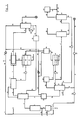
- FIG. 1 The inventive method is by FIG. 1 explained. Known measures, such as stabilizer additive, are not shown.
- the composed of ethylene, oxygen and CO 2 and inert and low organic content, such as acetic acid, existing recycle gas mixture, also referred to as recycle gas is passed via the line (1) in a formed as a plate column acetic acid evaporator (2), in which the gas stream with Acetic acid is charged, which is supplied via line (3).
- the gas mixture leaving the acetic acid evaporator (2) is fed to the vinyl acetate reactor (5) via a steam-heated line (4).
- the gaseous mixture leaving the vinyl acetate reactor (5) consisting essentially of ethylene, acetic acid, vinyl acetate, water, carbon dioxide, oxygen and inert gases, such as nitrogen and argon, is passed via line (6) to the first distillation column, the pre-dewatering column (7).
- the pre-dewatering column (7) is designed in a manner known per se.
- the gas mixture leaving the pre-dewatering column (7) passes via line (8) into a heat exchanger (9), where it is brought into countercurrent heat exchange with the return, which enters via line (16) and via line (10) into the pre-dewatering column (7) is returned.
- the gas mixture passes from the heat exchanger (9) via line (11) in a water-cooled condenser (12), in which it is cooled to about 35 ° C.
- the liquefied components pass via line (13) into containers (14), where they are collected.
- the portion of liquid exceeding a certain level in the collecting container (14) is pumped back into the pre-dewatering column (7) by means of pump (15) via line (16), heat exchanger (9) and line (10).
- the condensate accumulating in the sump (14) separates into two phases (17) and (18); From now on, the aqueous phase (17) is discharged via line (19) and only the organic phase (18) is wholly or partially via line (16), heat exchanger (9) and line (10) as reflux to the head of the pre-dewatering column (7) pumped back.
- the gas mixture leaving the condenser (12) via line (20) is washed with the acetic acid introduced via line (51) in the scrubbing column (21) (circulating gas scrubber) and freed from uncondensed vinyl acetate fractions.
- the bottom outlet from the cycle gas scrubber (21) is separated, wherein a partial flow through the conduit (22) is conducted in Umpump and is returned with cooling by means of the heat exchanger (23) to the lower part of the cycle gas scrubber (21), while the other part of the Sump drain via the line (24) through a heat exchanger (25) is passed, in which the sump trigger to a temperature of at least 30 ° C, preferably from 60 to 120 ° C and in particular from 60 to 100 ° C, heated.
- the thus heated bottom draw is then pumped back to the lower part of the pre-dewatering column (7), preferably to the 2nd to 15th, in particular to the 5th to 10th floor, calculated from the bottom of the column.
- liquid which consists mainly of vinyl acetate, acetic acid and water and contains almost all of the ethyl acetate is fed via line (31) a container (32), also referred to as Rohvinylacetatsammel personnel, fed and relaxed, preferably a pressure of 0.02 to 0.2 MPa, in particular to a pressure of 0.1 to 0.15 MPa.
- the formed return gas the predominantly ethylene and besides CO 2 , inerts such as nitrogen and argon, as well as organic components such as acetic acid, is discharged via the line (33), combined with the recirculated from line (57) return gas, which has approximately the same composition, and after compression in the recycle gas compressor (34) via the line (35) with the recirculated gas (26) recycled from the cycle gas scrubber (21).
- the organic phase which accumulates in the crude vinyl acetate collecting tank (32) is withdrawn via line (36) and introduced into the second distillation column (37), also called the azeotrope column.
- the overhead vapor of the second distillation column (37) is passed via line (38) in cooler (39) and condensed there.
- the condensate passing through the line (40) into the phase separator (41) separates into an aqueous phase (42), which is withdrawn via line (43) and an organic phase (44), which with the organic from the line (58) brought up Phase is merged.
- the combined in the phase separator (41) organic phase is removed by means of pump (45).
- a portion of the discharged organic phase is passed via the line (46) to the top of the Aezotropkolonne (37) and serves as reflux.
- the part not used as reflux is discharged via the line (47) and placed on a third distillation column (48), the dewatering column.
- the ethyl acetate passing via line (36) into column (37) is withdrawn from an enrichment zone above the bottom of column (37) via line (49).
- the bottom product of the column (37) contains almost completely obtained in the vinyl acetate working up acetic acid, at most 10 wt .-% water and small amounts of high boilers or polymers and only traces of vinyl acetate and ethyl acetate.
- the aqueous acetic acid is withdrawn from the bottom of the column (37) via line (50) and split.
- different amounts of acetic acid are required as washing liquid.
- the one for the Acetic acid wash in step e) required fraction is fed via line (51) and pump (52) of the wash column (21).
- the remainder is fed via the pump (53) and line (3) to the acetic acid evaporator (2).
- Fresh acetic acid is added to the top of the acetic acid evaporator (2) via line (54) according to the amount of acetic acid consumed in the reaction, and at the same time serves as a washing solution for the recirculated acetic acid introduced via line (3), which is also referred to as back acetic acid.
- the remainder of the organic phase (18) from collecting vessel (14) is fed via line (55), unless the entire organic phase (18) is used as reflux in the pre-dewatering column (7), to the flash tank (56).
- the return gas formed during the expansion to a pressure of 0.02 to 0.2 MPa, preferably to 0.1 to 0.15 MPa, is removed via line (57), combined with the return gas introduced via line (33) and after Compressed by the recycle gas compressor (34) via the line (35) fed back into the process.
- the liquid obtained in the container (56) is passed via line (58) onto the phase separator (41), from where the combined organic phases partly as reflux via the line (46) to the azeotrope column (37) and partly as inflow via the line (47) to the third distillation column (48), also called dewatering column.
- the feed to the dewatering column is almost free of acetic acid.
- the low boilers and last water residues contained in the overhead vapor of the column (48) are removed via line (59) and discharged from the work-up process.
- the measure essential for the work-up process according to the invention consists in the return of the heated acetic acid bottoms effluent from the scrubbing column (21) to the lower part of the pre-dewatering column (7), wherein the already heated, acetic acid bottoms effluent from the scrubbing column is reheated. Surprisingly, this measure is associated with many advantages.
- the total acetic acid is removed with the bottom of the azeotrope column (37), so that the feed to the dewatering column (48) and thus also to the pure vinyl acetate column (61) is acetic acid-free. Therefore, corrosion caused by acetic acid can be avoided in these parts of the system and less corrosion-resistant materials can be installed.
- By avoiding an acetic acid content in the feed to the pure vinyl acetate column (61) also reduces the distillation effort to obtain the pure vinyl acetate, since the separation of residual traces of acetic acid from vinyl acetate is very expensive. The distillation to obtain the pure vinyl acetate can therefore be operated with lower energy input and lower reflux ratio, which generally means a significant steam savings.
Landscapes
- Chemical & Material Sciences (AREA)
- Organic Chemistry (AREA)
- Crystallography & Structural Chemistry (AREA)
- Organic Low-Molecular-Weight Compounds And Preparation Thereof (AREA)
- Low-Molecular Organic Synthesis Reactions Using Catalysts (AREA)
Description
- Die vorliegende Erfindung betrifft ein Verfahren zur Isolierung von Vinylacetat aus dem Gasgemisch, das bei der Umsetzung von Ethylen mit Essigsäure und Sauerstoff aus Palladium oder Palladiumverbindungen enthaltenden Katalysatoren in der Gasphase gebildet wird, unter Rückführung der im Kreisgaswäscher anfallenden essigsauren Lösung in die erste Destillationskolonne.
- Die Herstellung von Vinylacetat durch Umsetzung von Ethylen mit Essigsäure und Sauerstoff oder sauerstoffhaltigen Gasen an Festbettkatalysatoren in der Gasphase ist bereits bekannt. Die Reaktion erfolgt im allgemeinen bei Drücken von 1 bis 2,5 MPa und Temperaturen von 100 bis 250°C. Geeignete Katalysatoren enthalten einen Edelmetallanteil und einen Aktivatoranteil. Der Edelmetallanteil besteht aus Palladium und/oder dessen Verbindungen; zusätzlich können noch Gold oder dessen Verbindungen anwesend sein. Der Aktivatoranteil besteht aus Verbindungen von Elementen der 1. Hauptgruppe und/oder der 2. Hauptgruppe und/oder Cadmium. Diese aktiven Komponenten werden auf Träger in feiner Verteilung aufgebracht, wobei als Tägermaterial im allgemeinen Kieselsäure oder Aluminiumoxid verwendet wird.
- Im allgemeinen liegt der Palladiumgehalt im Katalysator zwischen 0,5 und 5 Gew.-%.
- Wird Gold bzw. eine seiner Verbindungen eingesetzt, so wird es in einem Anteil von 0,01 bis 4 Gew.-% zugegeben.
- Jeder einzelne Aktivator wird im allgemeinen ebenfalls in einem Anteil von 0,01 bis 4 Gew.-% zugegeben. Bei allen drei Prozentangaben wird jeweils der Metallanteil der Komponente auf die Gesamtmasse des Trägerkatalysators bezogen. Bevorzugt sind folgende Katalysatoren: Palladium/Alkalielement/Cadmium sowie Palladium/Gold/Alkalielement, wobei Palladium bzw. Gold als Metalle oder Verbindungen im fertigen Katalysator vorliegen können und wobei als Alkalielement Kalium bevorzugt ist. Kalium wird in Form eines Carboxylats, insbesondere als Acetat, eingesetzt.
- Besonders bevorzugt sind die Katalysatoren Palladiumacetat/Kaliumacetat/Cadmiumacetat, sowie Palladiumacetat/Bariumacetoaurat/Kaliumacetat.
- In dem mehrstufigen katalytischen Prozess entstehen Vinylacetat und Wasser in äquimolaren Mengen, wie in der folgenden Bruttogleichung dargestellt:

- Aus der nicht ganz zu vermeidenden Totaloxidation des Ethylens entsteht CO2 und Wasser:
H2C=CH2 + 3 O2 → 2 CO2 + 2 H2O
- Es fällt daher mehr als 1 mol Wasser pro mol Vinylacetat an; im allgemeinen macht das Gewicht des Wassers ca. ein Vierteil des Gewichts des gebildeten Vinylacetats aus.
- Außer CO2 bilden sich in geringer Menge noch andere Nebenprodukte, darunter auch Ethylacetat, in einem Anteil von etwa 1000-2000 Gew.-ppm, bezogen auf das gebildete Vinylacetat.
- Ethylacetat darf in reinem Vinylacetat nur in einem geringen Anteil von höchstens 250 Gew.-ppm enthalten sein. Die Abtrennung von Ethylacetat erfordert einen hohen Energieaufwand und der Stand der Technik behandelt verschiedene Verfahren, den Energieaufwand bei der Reinigung von Vinylacetat unter Abtrennung von Ethylacetat und anderen Nebenprodukten zu reduzieren.
- Das zur Reaktion eingesetzte Gemisch enthält ein mehrfaches der stöchiometrisch erforderlichen Menge an Ethylen. Dementsprechend ist der Ethylenumsatz mit etwa 10% relativ gering und das nicht umgesetzte Ethylen muss in die Reaktionszone zurückgeführt werden. Vinylacetat wird üblicherweise in einem mehrstufigen Verfahren aus dem Gemisch der gasförmig anfallenden Reaktionsprodukte abgetrennt.
- Bei dem Verfahren gemäß
DE-A1-3 422 575 wird das den Vinylacetatreaktor verlassende heiße Gasgemisch, das im wesentlichen aus Ethylen, Essigsäure, Vinylacetat, Wasser, Kohlendioxid, Sauerstoff und Inerten, wie beispielsweise Stickstoff und Argon, besteht und das Ethylacetat enthält, in eine ohne zusätzliche Beheizung arbeitende erste Destillationskolonne eingeleitet, in die so genannte Vorentwässerungskolonne. Das am Kopf dieser Kolonne austretende Gasgemisch wird zunächst in einem Wärmetauscher mit dem Rücklauf auf die Vorentwässerungskolonne in Kontakt gebracht, wobei sich das Gasgemisch abkühlt und der Rücklauf entsprechend erwärmt. Das Gasgemisch gelangt anschließend aus dem Wärmetauscher in einen Kondensator. Die dabei verflüssigten Anteile werden in einem Sammelbehälter aufgefangen, in dem es zur Trennung in die wässrige und organische Phase kommt. Die wässrige Phase wird ausgeschleust während die organische Phase ganz oder teilweise als Rücklauf auf den Kopf der Vorentwässerungskolonne zurückgeführt wird. - Die nicht im Kondensator verflüssigten Anteile enthalten noch gasförmiges Vinylacetat. Dieses wird in einer mit Essigsäure als Waschflüssigkeit betriebenen Waschkolonne, die man auch als Kreisgaswäscher bezeichnet, aus dem Gasgemisch herausgewaschen. Das verbleibende Restgas wird zum Reaktor zurückgeführt. Der Sumpfablauf des Kreisgaswäschers sowie der Rest der aus dem Kondensat der Vorentwässerungskolonne verflüssigten organischen Phase wird in einem weiteren Behälter gesammelt, sofern nicht die gesamte aus dem Kondensat verflüssigte organische Phase als Rücklauf in der Vorentwässerungskolonne verwendet wird.
- Am Sumpf der Vorentwässerungskolonne fällt ein Gemisch an, das aus Vinylacetat, Essigsäure und etwa der Hälfte des Reaktionswassers sowie Nebenprodukten besteht. Die andere Hälfte des Reaktionswassers ist bereits ohne Energiezufuhr abgetrennt worden und bildet die wässrige Phase des Kondensats, das bei der Abkühlung des Kopfdampfes der Vorentwässerungskolonne entsteht.
- Das Sumpfprodukt der Vorentwässerungskolonne wird zunächst einem Sammelbehälter zugeführt, den man auch als Rohvinylacetatsammelbehälter bezeichnet, und anschließend in einer zweiten Destillationskolonne, der sogenannten Azeotropkolonne aufgearbeitet. Es fällt wassergesättigtes Vinylacetat als Kopfprodukt, ein Ethylacetat haltiger Seitenstrom sowie ein Sumpfprodukt an, das als Rückessigsäure in das System zurückgeführt wird. Der Ethylacetat haltige Seitenstrom wird ausgeschleust. Das wassergesättigte Vinylacetat, das nicht als Rücklauf auf den Kopf der zweiten Destillationskolonne gegeben wird, wird mit dem Sumpfablauf des Kreisgaswäschers und dem Rest der aus dem Kondensat der Vorentwässerungskolonne verflüssigten organischen Phase zusammengeführt.
- Anschließend wird das Gemisch auf eine weitere dritte Destillationskolonne, auf die sogenannte Entwässerungskolonne gegeben. Der Kopfdampf an dieser Kolonne wird nach Kondensation nahezu vollständig als Rücklauf zurückgeführt. Der Seitenstromabzug wird in eine wässrige und organische Phase getrennt, wobei dann die wässrige Phase ausgeschleust und die organische Phase wieder auf die Kolonne gegeben wird. Am Boden der Entwässerungskolonne wird ein trockenes Vinylacetat/Essigsäuregemisch abgezogen und auf eine weitere vierte Kolonne, auf die sogenannte Reinvinylacetatkolonne gegeben. Bei dieser Kolonne fällt als Kopfprodukt nahezu ethylacetatfreies Vinylacetat an, während der Sumpf dieser Kolonne, der Essigsäure, Hochsieder und Spuren von Vinylacetat und Ethylacetat enthält, unter Ausschleusen eines Teilstromes wieder in den Prozess zurückgeführt wird.
- Eine weitere Variante des bekannten Verfahrens zur Aufarbeitung von Vinylacetat ist aus
EP-A2-0 423 658 bekannt. Danach wird das Sumpfprodukt des Kreisgaswäschers nicht unmittelbar mit dem an der Azeotropkolonne anfallenden wasserhaltigen Vinylacetat zusammengeführt sondern zuerst in eine weitere Kolonne eingeleitet, in der als Kopfprodukt ein Vinylacetat-Wasser-Azeotrop und als Sumpfprodukt Essigsäure anfällt, die in den Prozess zurückgeführt wird. Das in dieser zusätzlichen Kolonne anfallende wässrige Vinylacetat wird mit dem aus der Azeotropkolonne erhaltenen wassergesättigtem Vinylacetat vereinigt und entsprechend dem Verfahren nachDE-A1-3 422 575 in der nachgeschalteten Entwässerungskolonne und Reinvinylacetatkolonne aufgearbeitet. Das Verfahren gemäßEP-A2-0 423 658 erfordert zur Ethylacetatabtrennung etwa denselben Aufwand an Destillationsenergie wie das Verfahren gemäßDE-A1-3 422 575 , allerdings ist eine geringere Zahl an Kolonnenböden erforderlich, was weniger Investitionskosten bedeutet. Der nicht kondensierte Teil des Vinylacetats aus der Vorentwässerungskolonne, der in dem Kreisgaswäscher mit Essigsäure herausgewaschen wird und als essigsaure Lösung anfällt, sowie die organische Phase des Kondensats aus der Vorentwässerungskolonne enthalten nahezu kein Ethylacetat mehr und eine energetisch aufwendige Befreiung dieser Vinylacetatströme von Ethylacetat entfällt. Allerdings erfordert diese Verfahrensvariante den Betrieb einer zusätzlichen Destillationskolonne zur Auftrennung des Sumpfablaufs aus dem Kreisgaswäscher. - Die bekannten Aufarbeitungsverfahren zur Gewinnung von reinem Vinylacetat weisen immer noch gewisse Nachteile auf. So enthält der Sumpfablauf des Kreisgaswäschers und der Sumpfablauf der Vorentwässerungskolonne erhebliche Mengen an Gasen gelöst, vor allem an Ethylen. Bei der Entspannung des Sumpfablaufs aus der Vorentwässerungskolonne und aus dem Kreisgaswäscher in dem Rohvinylacetatsammelbehälter wird daher eine beachtliche Menge Rückgas frei, die unter hohem Energieaufwand in einem Rückgasverdichter aufzukomprimieren ist, bevor sie wieder in den Reaktionskreislauf zurückgeführt werden kann. Im Allgemeinen wird das rohe Vinylacetat von einem Druck im Bereich von 0,5 bis 2,0 MPa auf eine Druckstufe von 0,02 bis 0,2 MPa entspannt. Das bei der Entspannung gebildete Gas enthält überwiegend Ethylen sowie Kohlendioxid, Stickstoff und weitere Inerte wie Argon sowie organische Bestandteile wie Essigsäure und geringe Mengen an Vinylacetat und Ethylacetat. Man bezeichnet dieses Gas auch als Rückgas, das in den Prozess zurückgeführt wird.
- Charakteristisch für den bekannten Aufarbeitungsprozess ist das Zusammenführen der aus dem Sumpfablauf des Kreisgaswäschers anfallenden essigsauren Lösung mit dem wassergesättigten Vinylacetat aus dem Kopfprodukt der Azetropkolonne und dem Rest der aus dem Kondensat der Vorentwässerungskolonne verflüssigten organischen Phase. Daher wird den weiteren Reinigungsstufen, die in der nachgeschalteten Entwässserungskolonne und Reinvinylacetatkolonne erfolgen, ein essigsaures Gemisch zugeführt, aus dem unter hohem Energieaufwand Essigsäure abgetrennt werden muss. Zudem müssen Entwässerungskolonne und Reinvinylacetatkolonne mit korrosionsbeständigen Materialien, die gegenüber Essigsäure unempfindlich sind, ausgelegt werden.
- Ebenfalls enthält das Kondensat der Vorentwässerungskolonne, das nicht als Rücklauf auf den Kopf der Vorentwässerungskolonne zurückgegeben wird, noch eine gewisse Menge Ethylacetat. Da dieser Stoffstrom erst nach der Azeotropkolonne mit dem dort als Kopfprodukt anfallenden, wassergesättigten Vinylacetat zusammengeführt wird, wird der nachgeschalteten Entwässerungs- und Reinvinylacetatkolonne ein ethylacetathaltiger Stoffstrom zugeführt, aus dem Ethylacetat nur unter hohem Energieaufwand abgetrennt werden kann.
- Schließlich ist eine verbesserte Abtrennung von Wasser und Ethylacetat an einer möglichst vorgeschalteten Aufarbeitungsstufe erstrebenswert, um das Durchschleppen dieser unerwünschten Stoffe durch den gesamten Aufarbeitungsprozess möglichst zu unterbinden und die damit verbundene, energetisch aufwendige Abtrennung bei der Reinvinylacetatdestillation zu vermeiden.
- Die Erfindung besteht daher in einem Verfahren zur Abtrennung von Vinylacetat aus dem Gasgemisch, das bei der Umsetzung von Ethylen mit Essigsäure und Sauerstoff an Palladium oder Palladiumverbindungen enthaltenden Katalysatoren in der Gasphase gebildet wird, wobei man
- a) das aus der Reaktionszone austretende Gasgemisch in eine erste Destillationskolonne einleitet,
- b) das am Kopf der ersten Destillationskolonne austretende Gasgemisch auf -20 bis +50°C abkühlt, wobei sich das anfallende Kondensat in eine Wasserphase und in eine organische Phase trennt,
- c) die in Schritt b) gebildete Wasserphase abzieht,
- d) die in Schritt b) gebildete organische Phase ganz oder teilweise als Rücklauf auf den Kopf der in Schritt a) benutzten ersten Destillationskolonne zurückführt und einen nicht als Rücklauf verwendeten Teil der organischen Phase abzieht,
- e) das in Schritt b) nicht kondensierte, Vinylacetat haltige Gas in einer Waschkolonne mit mindestens 90%iger wässriger Essigsäure wäscht und dabei am Sumpf eine Vinylacetat haltige, essigsaure Lösung gewinnt,
- f) das Vinylacetat, Ethylacetat, Essigsäure und Wasser enthaltende Sumpfprodukt von Schritt a) einem Sammelbehälter zuführt und die unter Druck stehende Flüssigkeit entspannt, wobei sich ein Gas bildet,
- g) die bei der Entspannung in Schritt f) anfallende Flüssigkeit einer zweiten Destillationskolonne zuführt und aus einer Anreicherungszone oberhalb von deren Sumpf einen Ethylacetat haltigen Seitenstrom abzieht,
- h) das Essigsäure und Wasser enthaltende Sumpfprodukt von Schritt g) ganz oder teilweise zur Gaswäsche in Schritt e) benutzt,
- i) den Kopfdampf von Schritt g) abkühlt, wobei sich das anfallende Kondensat in eine wässrige und eine organische Phase trennt,
- j) die in Schritt i) gebildete wässrige Phase abzieht,
- k) einen Teil der in Schritt i) gebildeten organischen Phase als Rücklauf auf den Kopf der in Schritt g) benutzten zweiten Destillationskolonne zurückführt und den restlichen Teil abzieht, dadurch gekennzeichnet, dass man
- l) einen Teil des Sumpfproduktes der in Schritt e) benutzten Waschkolonne unter Umpump zunächst kühlt und in den Sumpf der in Schritt e) benutzten Waschkolonne zurückführt, den restlichen Teil abzieht und den abgezogenen Teil auf eine Temperatur von wenigstens 30°C erwärmt und auf den unteren Teil der in Schritt a) benutzten ersten Destillationskolonne gibt,
- m) die in Schritt d) abgezogene restliche organische Phase entspannt, das bei der Entspannung gebildete Gas mit dem in Schritt f) gebildeten Gas vereinigt und das gemeinsame Gas wieder in den Prozess zurückführt,
- n) die in Schritt m) anfallende organische Phase mit der in Schritt i) anfallenden organischen Phase vereinigt und den in Schritt k) restlichen abgezogenen, nicht als Rücklauf verwendeten Teil der organischen Phase in eine dritte Destillationskolonne einleitet,
- o) das Kopfprodukt der dritten Destillationskolonne aus Schritt n) abkühlt und die dabei anfallenden Leichtsieder und das dabei anfallende Wasser abtrennt,
- p) das Sumpfprodukt der dritten Destillationskolonne aus Schritt n) in eine vierte Destillationskolonne einleitet,
- q) am Kopf der in Schritt p) verwendeten vierten Destillationskolonne reines Vinylacetat abzieht.
- In Schritt a) wird vorzugsweise das aus der Reaktionszone austretende Gasgemisch zunächst im Gegenstromwärmeaustausch mit dem kälteren Kreisgas, das damit aufgeheizt und dann zur Reaktion zurückgeführt wird, auf 115°C-150°C abgekühlt. Dabei tritt noch keine Kondensation der verflüssigbaren Anteile ein und das Gasgemisch wird in die erste Destillationskolonne, auch Vorentwässerungskolonne genannt, eingeleitet.
- Die Menge der in Schritt b) gebildeten organischen Phase ist abhängig davon, bis zu welcher Temperatur in diesem Schritt abgekühlt wird. Denjenigen Teil der organischen Phase aus Schritt b), den man für Schritt d) nicht als Rücklauf benutzt, zieht man ab und entspannt in Schritt m) von einer Druckstufe von 0,5 bis 2,0 MPa auf eine Druckstufe von 0,02 bis 0,2 MPa, vorzugsweise auf 0,1 bis 0,15 MPa. Die dabei anfallende Flüssigkeit vereinigt man in Schritt n) mit der organischen Phase aus dem kondensierten Kopfprodukt der zweiten Destillationskolonne, auch Azeotropkolonne genannt (Schritt i). Vorzugsweise werden beide organische Phasen im Phasentrenner der Azeotropkolonne vereinigt. Der in Schritt n) nicht als Rücklauf auf den Kopf der Azeotropkolonne gegebene Anteil der organischen Phase wird in eine dritte Destillationskolonne, die man auch als Entwässerungskolonne bezeichnet, eingeleitet.
- Vorzugsweise wählt man die Abkühlungstemperatur in Schritt b) und den als Rücklauf in Schritt d) benutzten Anteil der in b) gebildeten organischen Phase derart, dass möglichst wenig Vinylacetat, aber möglichst das gesamte Ethylacetat im Sumpfprodukt von Schritt a) enthalten sind.
- Charakteristisch für die erfindungsgemäße Arbeitsweise ist der Betrieb der in Schritt e) verwendeten Waschkolonne und die Rückführung des Sumpfablaufs aus der Waschkolonne auf den unteren Teil der in Schritt a) verwendeten ersten Destillationskolonne. Ein Teil des Sumpfabzugs aus der Waschkolonne, die man auch als Kreisgaswäscher bezeichnet, wird im Umpump geführt, wobei der im Umpump geführte Teil des Sumpfproduktes aus der Waschkolonne abgekühlt wird. Zur Abkühlung des Sumpfproduktes werden Mittel verwendet, die dem Fachmann gebräuchlich sind, beispielsweise Wärmetauscher. Der nicht in den Umpump geführte Teil des Sumpfproduktes wird aus der Waschkolonne abgezogen, auf eine Temperatur von wenigstens 30°C, vorzugsweise von 60°C bis 120°C, insbesondere von 60°C bis 100°C, erwärmt und auf den unteren Teil der in Schritt a) verwendeten ersten Destillationskolonne gefahren. Zweckmäßigerweise wird zur Erwärmung das aus der Waschkolonne abgepumpte Sumpfprodukt durch einen Wärmtauscher geleitet.
- Vorzugsweise wird der erwärmte Sumpfablauf aus Schritt I) auf den 2. bis 15., insbesondere auf den 5. bis 10. Boden, gerechnet vom Kolonnenboden, der ersten Destillationskolonne gegeben.
- Durch die Rückführung des erwärmten Sumpfproduktes aus der Waschkolonne aus Schritt e) auf den unteren Teil der in Schritt a) verwendeten ersten Destillationskolonne wird die Temperatur des Sumpfablaufs der Waschkolonne, dessen Temperatur ohne diese Maßnahme im allgemeinen bei 30 bis 50°C liegt, deutlich erhöht. Dabei wird zunächst in einem ersten Schritt der Sumpfablauf, beispielsweise in einem Wärmetauscher, auf eine Temperatur von wenigstens 30°C, vorzugsweise von 60°C bis 120°C und insbesondere von 60°C bis 100°C, erwärmt. Bei der Aufgabe des so erwärmten Sumpfablaufs des Kreisgaswäschers auf den unteren Teil der ersten Destillationskolonne wird dieser Stoffstrom nochmals erwärmt, im allgemeinen auf eine Temperatur von 80°C bis 150°C, was auch der Temperatur des Sumpfablaufs der ersten Destillationskolonne entspricht. Durch dieses Aufheizen des Sumpfablaufs der Waschkolonne verringert sich die Löslichkeit der gasförmigen Komponenten in dem essigsauren, rohen Vinylacetat. Die gasförmigen Komponenten, insbesondere Ethylen und Kohlendioxid, werden verstärkt über den Kopf der ersten Destillationskolonne ausgetrieben und an einer sehr frühen Stelle des Aufarbeitungsprozesses wieder in den Gaskreislauf zurückgeführt. Bei der Entspannung des Rohproduktes fällt daher weniger Gas an. Die Entspannung erfolgt dabei in einem Sammelbehälter, auch Rohvinylacetatsammelbehälter genannt, von einer Druckstufe von 0,5 bis 2,0 MPa auf eine Druckstufe von 0,02 bis 0,2 MPa, vorzugsweise auf 0,1 bis 0,15 MPa. Das bei der Entspannung anfallende Gas bezeichnet man auch als Rückgas und es enthält überwiegend Ethylen und daneben Kohlendioxid und weitere Inerte wie Stickstoff und Argon sowie auch organische Bestandteile wie Essigsäure und geringe Mengen an Vinylacetat und Ethylacetat. Bei der Rückführung des Rückgases in den Prozess ist daher ein geringerer Energieaufwand erforderlich, um das Rückgas wieder auf die Druckstufe des Reaktors zu komprimieren. Durch die erfindungsgemäße Rückführung des Sumpfablaufs aus der Waschkolonne aus Schritt e) wird daher der Rückgasverdichter entlastet, was eine bedeutende Energieeinsparung mit sich bringt.
- Weiterhin wird durch die Aufgabe der essigsauren Lösung aus der Waschkolonne auf den unteren Teil der ersten Destillationskolonne, vorzugsweise auf den 2. bis 15. Boden, insbesondere auf den 5. bis 10. Boden, gerechnet vom Kolonnenboden, eine Waschwirkung erzielt. Ethylacetat wird in den Sumpf der ersten Destillationskolonne gewaschen und über den Sumpf ausgeschleust.
- Vinylacetat befindet sich in dem Sumpfprodukt der ersten Destillationskolonne, in der in Schritt e) gebildeten essigsauren Waschlösung, die in Schritt l) auf den unteren Teil der ersten Destillationskolonne zurükgeführt wird sowie in dem nicht als Rücklauf in Schritt d) benutzten Anteil der in Schritt b) gebildeten organischen Phase. Der Vinylacetatgehalt in diesen drei Stoffströmen hängt von der Anlagenfahrweise ab und ist für die Durchführung des erfindungsgemäßen Verfahrens nicht kritisch.
- Das Kopfprodukt der ersten Destillationskolonne enthält nur noch sehr geringen Mengen an Ethylacetat und der in Schritt d) zurückgeführte Rücklauf sowie der nicht als Rücklauf verwendete Teil der organischen Phase ist ethylacetatarm und kann ohne weitere Maßnahmen, die eine Ethylacetatabtrennung erfordern, weiterverarbeitet werden. Dazu wird nach Schritt m) die abgezogene organische Phase entspannt und die dabei anfallende Flüssigkeit mit der in Schritt i) anfallenden organischen Phase vereinigt, die aus dem Kopfprodukt der zweiten Destillationskolonne, auch Azeotropkolonne genannt, erhalten wird. Die zusammengeführten organischen Phasen werden teilweise als Rücklauf auf den Kopf der Azeotropkolonne zurückgeführt. Der Rest wird auf die dritte Destillationskolonne, auch als Entwässerungskolonne bezeichnet, gegeben (Schritt n).
- Das bei der Entspannung in Schritt m) anfallende Gas bezeichnet man auch als Rückgas und weist etwa die gleiche Zusammensetzung auf, wie das in Schritt f) anfallende Rückgas. Beide Rückgasströme werden vereinigt, dann in einem Rückgasverdichter aufkomprimiert und anschließend in den Prozess zurückgeführt. Zweckmäßigerweise wird das vereinigte Rückgas mit dem bei der Essigsäurewäsche in Schritt e) anfallenden Restgas, das man auch als Kreisgas bezeichnet, vereinigt. Die vereinigten Gasströme werden komprimiert und nach Ausschleusung eines Inerte enthaltenden Anteils wieder in den Vinylacetatreaktor zurückgeführt.
- In der Gaswäsche von Schritt e) setzt man zumindest teilweise das Sumpfprodukt der zweiten Destillationskolonne (Schritt g)) ein. Das Sumpfprodukt besteht hauptsächlich aus Essigsäure und enthält höchstens 10 Gew.-% Wasser. Ein nicht in Schritt e) benötigter Anteil des Sumpfprodukts wird vorzugsweise als Rückessigsäure zum Reaktor zurückgeführt, nachdem ein kleiner Teil zur Entfernung von Hochsiedern und Polymeren ausgeschleust wurde.
- In Schritt n) führt man vorzugsweise nur soviel von der aus Schritt i) und m) zusammengeführten organischen Phase als Rücklauf zurück, dass der Kopfdampf der zweiten Destillationskolonne möglichst wenig Ethylacetat enthält. Denjenigen Teil der organischen Phase, der nicht für diesen Zweck benötigt wird, leitet man in die dritte Destillationskolonne, auch Entwässerungskolonne genannt, ein.
- In Schritt o) wird das kondensiert Kopfprodukt der dritten Destillationskolonne nicht ganz als Rücklauf benutzt, sondern es wird ein zur Leichtsieder- und Wasserabtrennung ausreichender Teil abgezogen.
- In Schritt p) wird der Sumpfablauf der dritten Destillationskolonne, der nahezu aus trockenem Vinylacetat besteht, auf eine vierte Destillationskolonne, der sogenannten Reinvinylacetatkolonne, an der reines Vinylacetat als Kopfprodukt abgezogen wird, gegeben (Schritt q).
- Die in dem beanspruchten Aufarbeitungsverfahren von Vinylacetat benutzte erste, zweite, dritte und vierte Destillationskolonne werden bei solchen Temperatur-, Druck- und Rücklaufverhältnissen betrieben, die sich von der Anlagenauslastung her ergeben.
- Das erfindungsgemäße Verfahren wird durch
Figur 1 erläutert. An sich bekannte Maßnahmen, wie Stabilisatorzusatz, werden nicht dargestellt. - Das aus Ethylen, Sauerstoff und CO2 sowie Inerten und geringen organischen Anteilen, wie Essigsäure, bestehende zurückgeführte Gasgemisch, auch als Kreisgas bezeichnet, wird über die Leitung (1) in einen als Bodenkolonne ausgebildeten Essigsäureverdampfer (2) geleitet, in dem der Gasstrom mit Essigsäure beladen wird, die über Leitung (3) zugeführt wird. Das den Essigsäureverdampfer (2) verlassende Gasgemisch wird über eine dampfbeheizte Leitung (4) dem Vinylacetatreaktor (5) zugeführt.
- Das den Vinylacetatreaktor (5) verlassende Gasgemisch, das im wesentlichen aus Ethylen, Essigsäure, Vinylacetat, Wasser, Kohlendioxid, Sauerstoff sowie inerten Gasen, wie zum Beispiel Stickstoff und Argon besteht, wird über die Leitung (6) in die erste Destillationskolonne, die Vorentwässerungskolonne (7), eingeleitet. Die Vorentwässerungskolonne (7) wird in an sich bekannter Weise ausgelegt.
- Das aus der Vorentwässerungskolonne (7) über Kopf austretende Gasgemisch gelangt über Leitung (8) in einen Wärmetauscher (9), wo es in Gegenstromwärmeaustausch mit dem Rücklauf gebracht wird, der über Leitung (16) eintritt und über Leitung (10) in die Vorentwässerungskolonne (7) zurückgeführt wird. Das Gasgemisch gelangt aus dem Wärmetauscher (9) über Leitung (11) in einen wassergekühlten Kondensator (12), in dem es auf etwa 35°C abgekühlt wird. Die dabei verflüssigten Anteile gelangen über Leitung (13) in Behälter (14), wo sie gesammelt werden. Der ein bestimmtes Niveau im Sammelbehälter (14) überschreitende Anteil an Flüssigkeit wird mittels Pumpe (15) über Leitung (16), Wärmetauscher (9) und Leitung (10) in die Vorentwässerungskolonne (7) zurückgepumpt. Nach einiger Zeit trennt sich das im Sammelbehälter (14) anfallende Kondensat in zwei Phasen (17) und (18); von nun an wird die wässrige Phase (17) über Leitung (19) ausgeschleust und nur die organische Phase (18) wird ganz oder teilweise über Leitung (16), Wärmetauscher (9) und Leitung (10) als Rücklauf auf den Kopf der Vorentwässerungskolonne (7) zurückgepumpt.
- Das den Kondensator (12) über Leitung (20) verlassende Gasgemisch wird mit der über Leitung (51) herangeführten Essigsäure in der Waschkolonne (21) (Kreisgaswäscher) gewaschen und von nicht kondensierten Vinylacetatanteilen befreit. Der Sumpfablauf aus dem Kreisgaswäscher (21) wird getrennt, wobei ein Teilstrom über die Leitung (22) im Umpump geführt wird und unter Kühlung mittels des Wärmetauschers (23) auf den unteren Teil des Kreisgaswäschers (21) zurückgeführt wird, während der andere Teil des Sumpfablaufs über die Leitung (24) durch einen Wärmetauscher (25) geleitet wird, in dem der Sumpfabzug auf eine Temperatur von wenigstens 30°C, vorzugsweise von 60 bis 120°C und insbesondere von 60 bis 100°C, erwärmt wird. Der so erwärmte Sumpfabzug wird anschließend auf den unteren Teil der Vorentwässerungskolonne (7) zurückgepumpt, vorzugsweise auf den 2. bis 15., insbesondere auf den 5. bis 10. Boden, gerechnet vom Kolonnenboden.
- Das die Waschkolonne (21) über Leitung (26) verlassende Restgas oder Kreisgas (Ethylen, nicht umgesetzter Sauerstoff und als Nebenprodukt gebildetes CO2), wird mit dem über Leitung (35) zugeführten Rückgas, das überwiegend Ethylen und daneben CO2, Inerte wie Stickstoff und Argon, sowie Essigsäure und geringe Mengen an Vinylacetat und Ethylacetat enthält, vereinigt, mittels des Kreisgaskompressor (27) komprimiert und über Leitung (1) und den Essigsäureverdampfer (2) zum Reaktor (5) zurückgeführt. Ein Teil des Kreisgases wird zur Ausschleusung von inerten Bestandteilen über Leitung (28) als Abgas entfernt. Über Leitung (29) wird frisches Ethylen und über Leitung (30) frischer Sauerstoff zugeführt.
- Die am Sumpf der Vorentwässerungskolonne (7) anfallende Flüssigkeit, die hauptsächlich aus Vinylacetat, Essigsäure und Wasser besteht und fast das gesamte Ethylacetat enthält, wird über Leitung (31) einem Behälter (32), auch als Rohvinylacetatsammelbehälter bezeichnet, zugeführt und entspannt, vorzugsweise auf einen Druck von 0,02 bis 0,2 MPa, insbesondere auf einen Druck von 0,1 bis 0,15 MPa. Das sich dabei gebildete Rückgas, das überwiegend Ethylen und daneben CO2, Inerte wie Stickstoff und Argon, sowie organische Bestandteile, wie Essigsäure enthält, wird über die Leitung (33) abgeführt, mit dem aus Leitung (57) herangeführten Rückgas, das etwa die gleiche Zusammensetzung aufweist, vereinigt, und nach Komprimierung im Rückgasverdichter (34) über die Leitung (35) mit dem über Leitung (26) herangeführten Kreisgas aus dem Kreisgaswäscher (21) vereinigt. Die in dem Rohvinylacetatsammelbehälter (32) nach Entspannung anfallende organische Phase wird über die Leitung (36) abgezogen und in die zweite Destillationskolonne (37), auch Azeotropkolonne genannt, eingeleitet.
- Der Kopfdampf der zweiten Destillationskononne (37) wird über Leitung (38) in Kühler (39) geleitet und dort kondensiert. Das über Leitung (40) in den Phasentrenner (41) gelangende Kondensat trennt sich in eine wässrige Phase (42), die über Leitung (43) abgezogen wird und eine organische Phase (44), die mit der aus Leitung (58) herangeführten organischen Phase zusammengeführt wird. Die im Phasentrenner (41) vereinigte organische Phase wird mittels Pumpe (45) abgeführt. Ein Teil der abgeführten organischen Phase wird über die Leitung (46) auf den Kopf der Aezotropkolonne (37) gegeben und dient dort als Rücklauf. Der nicht als Rücklauf verwendete Teil wird über die Leitung (47) abgeführt und auf eine dritte Destillationskolonne (48), die Entwässerungskolonne, gegeben. Das über Leitung (36) in Kolonne (37) gelangende Ethylacetat wird aus einer Anreicherungszone oberhalb des Sumpfes der Kolonne (37) über Leitung (49) abgezogen. Das Sumpfprodukt der Kolonne (37) enthält nahezu vollständig die in der Vinylacetataufarbeitungsstufe anfallende Essigsäure, höchstens 10 Gew.-% Wasser sowie geringe Mengen Hochsieder bzw. Polymere und nur noch Spuren von Vinylacetat und Ethylacetat.
- Die wässrige Essigsäure wird aus dem Sumpf der Kolonne (37) über die Leitung (50) abgezogen und aufgeteilt. Je nach Auslegung der Waschkolonne (21) und der Temperatur des zu waschenden Gases werden unterschiedliche Mengen an Essigsäure als Waschflüssigkeit benötigt. Der für die Essigsäurewäsche in Schritt e) benötigte Anteil wird über Leitung (51) und Pumpe (52) der Waschkolonne (21) zugeführt. Der Rest wird über Pumpe (53) und Leitung (3) dem Essigsäureverdampfer (2) zugeführt. Frische Essigsäure wird über Leitung (54) entsprechend der bei der Reaktion verbrauchten Essigsäuremenge auf den Kopf des Essigsäureverdampfers (2) gegeben und dient gleichzeitig als Waschlösung für die über Leitung (3) herangeführte, wiedergewonnenen Essigsäure, die man auch als Rückessigsäure bezeichnet.
- Der Rest der organischen Phase (18) aus Sammelbehälter (14) wird über die Leitung (55), falls nicht die gesamte organische Phase (18) als Rücklauf in der Vorentwässerungskolonne (7) verwendet wird, dem Entspannungsbehälter (56) zugeführt. Das bei der Entspannung auf einen Druck von 0,02 bis 0,2 MPa, vorzugsweise auf 0,1 bis 0,15 MPa gebildete Rückgas wird über die Leitung (57) abgeführt, mit dem über Leitung (33) herangeführten Rückgas vereinigt und nach Verdichtung mittels des Rückgasverdichters (34) über die Leitung (35) in den Prozess zurückgeführt.
- Die im Behälter (56) anfallende Flüssigkeit wird über Leitung (58) auf den Phasentrenner (41) gegeben, von wo aus die zusammengeführten organischen Phasen zum Teil als Rücklauf über die Leitung (46) auf die Azeotropkolonne (37) und zum Teil als Zufluß über die Leitung (47) auf die dritte Destillationskolonne (48), auch Entwässerungskolonne genannt, gegeben werden. Der Zulauf zur Entwässerungskolonne ist nahezu essigsäurefrei.
- Die im Kopfdampf der Kolonne (48) enthaltenen Leichtsieder und letzte Wasserreste werden über die Leitung (59) abgeführt und aus dem Aufarbeitungsprozess ausgeschleust.
- Das nahezu wasserfreie Vinylacetat, das am Sumpf der Kolonne (48) anfällt, wird über Leitung (60) zur vierten Destillationskolonne (61), auch Reinvinylacetatkolonne genannt, geführt. Der Kopfdampf dieser Kolonne geht über Leitung (62) zum Kondensator (63). Das anfallende Kondensat ist Ethylacetat freies reines Vinylacetat. Über Leitung (64) wird ein sehr kleiner Teil dieses Vinylacetats als Rücklauf in die Kolonne (61) zurückgeleitet. Über Leitung (65) wird reines Vinylacetat abgezogen. Das Sumpfprodukt der Kolonne (61), das geringe Mengen an Ethylacetat, Polymere und Hochsieder enthält, wird über Leitung (66) und Pumpe (67) zurückgeführt zur Kolonne (37). Aus dem Essigsäureverdampfer (2), in dem letztlich alle Hochsieder und Polymere zurückgeführt werden, wird über Leitung (67) ein Teilstrom zur Polymerenausschleusung abgezogen.
- Die für das erfindungsgemäße Aufarbeitungsverfahren wesentliche Maßnahme besteht in der Rückführung des erwärmten, essigsauren Sumpfablaufs aus der Waschkolonne (21) in den unteren Teil der Vorentwässerungskolonne (7), wobei sich der schon erwärmte, essigsaure Sumpfablauf aus der Waschkolonne nochmals erwärmt. Überraschenderweise ist diese Maßnahme mit vielfältigen Vorteilen verbunden.
- Durch diese Maßnahme erniedrigt sich die Löslichkeit der in dem Sumpfablauf des Kreisgaswäschers enthaltenen gasförmigen Komponenten, insbesondere von Ethylen und Kohlendioxid, die über den Kopf der ersten Destillationskolonne ausgetrieben werden und an einer frühen Prozessstufe wieder in das Kreisgas zurückgeschleust werden.
- Dadurch fällt bei der Entspannung weniger Rückgas an, das unter geringerem Energieaufwand in dem Rückgasverdichter (34) aufkomprimiert und in den Prozess zurückgeschleust wird. Der Rückgasverdichter wird somit entlastet.
- Durch die Aufgabe des erwärmten, essigsauren Sumpfablaufs aus der Waschkolonne (21) auf den unteren Teil der Vorentwässerungskolonne (7) wird eine Waschwirkung erzielt und nahezu das gesamte Ethylacetat wird in den Sumpf der Vorentwässerungskolonne (7) gewaschen und über den Sumpfablauf ausgeschleust. Nur ein sehr geringer Anteil an Ethylacetat wird in die organische Phase (18), die sich im Sammelbehälter (14) ansammelt, mitgeschleppt. Der über Leitung (55) abgezogene Stoffstrom enthält daher kaum noch Ethylacetat. Sein Anteil kann daher im Vergleich zu der bekannten Arbeitsweise verstärkt gefahren werden, wodurch die Belastung der Azeotropkolonne (37) gemindert wird, was ebenfalls zu weiteren Energieeinsparungen führt. So kann die Azeotropkolonne mit einem deutlich niedrigeren Rücklaufverhältnis betrieben werden im Vergleich zu der bekannten Arbeitsweise.
- Ebenfalls wird eine im Vergleich zu der bekannten Arbeitsweise größere Wassermenge über den Kopf der Vorentwässerungskolonne (7) abgeführt, wodurch sich der Wasseranfall in dem Behälter (14) erhöhen lässt. Daher kann die Wasserentfernung über die Vorentwässrungskolonne (7) effektiver betrieben werden. Wasser wird somit an einer frühen Prozessstufe verstärkt entfernt und spätere Prozessstufen zur Wasserentfernung werden entlastet.
- Ferner wird die gesamte Essigsäure mit dem Sumpf der Azeotropkolonne (37) abgeführt, so dass der Zulauf zur Entwässerungskolonne (48) und damit auch zur Reinvinylacetatkolonne (61) essigsäurefrei ist. Daher lassen sich in diesen Anlagenteilen durch Essigsäure verursachte Korrosionserscheinungen vermeiden und es können weniger korrosionsbeständige Materialien verbaut werden. Durch die Vermeidung eines Essigsäuregehalts in dem Zulauf zur Reinvinylacetatkolonne (61) verringert sich auch der Destillationsaufwand zur Gewinnung des reinen Vinylacetats, da die Abtrennung von Restspuren von Essigsäure aus Vinylacetat sehr aufwendig ist. Die Destillation zur Gewinnung des reinen Vinylacetats kann daher unter geringerem Energieeinsatz und geringerem Rücklaufverhältnis betrieben werden, was im allgemeinen eine erhebliche Dampfeinsparung bedeutet.
Claims (11)
- Verfahren zur Abtrennung von Vinylacetat aus dem Gasgemisch, das bei der Umsetzung von Ethylen mit Essigsäure und Sauerstoff an Palladium oder Palladiumverbindungen enthaltenden Katalysatoren in der Gasphase gebildet wird, wobei mana) das aus der Reaktionszone austretende Gasgemisch in eine erste Destillationskolonne einleitet,b) das am Kopf der ersten Destillationskolonne austretende Gasgemisch auf -20 bis +50°C abkühlt, wobei sich das anfallende Kondensat in eine Wasserphase und in eine organische Phase trennt,c) die in Schritt b) gebildete Wasserphase abzieht,d) die in Schritt b) gebildete organische Phase ganz oder teilweise als Rücklauf auf den Kopf der in Schritt a) benutzten ersten Destillationskolonne zurückführt und einen nicht als Rücklauf verwendeten Teil der organischen Phase abzieht,e) das in Schritt b) nicht kondensierte, Vinylacetat haltige Gas in einer Waschkolonne mit mindestens 90%iger wässriger Essigsäure wäscht und dabei am Sumpf eine Vinylacetat haltige, essigsaure Lösung gewinnt,f) das Vinylacetat, Ethylacetat, Essigsäure und Wasser enthaltende Sumpfprodukt von Schritt a) einem Sammelbehälter zuführt und die unter Druck stehende Flüssigkeit entspannt, wobei sich ein Gas bildet,g) die bei der Entspannung in Schritt f) anfallende Flüssigkeit einer zweiten Destillationskolonne zuführt und aus einer Anreicherungszone oberhalb von deren Sumpf einen Ethylacetat haltigen Seitenstrom abzieht,h) das Essigsäure und Wasser enthaltende Sumpfprodukt von Schritt g) ganz oder teilweise zur Gaswäsche in Schritt e) benutzt,i) den Kopfdampf von Schritt g) abkühlt, wobei sich das anfallende Kondensat in eine wässrige und eine organische Phase trennt,j) die in Schritt i) gebildete wässrige Phase abzieht,k) einen Teil der in Schritt i) gebildeten organischen Phase als Rücklauf auf den Kopf der in Schritt g) benutzten zweiten Destillationskolonne zurückführt und den restlichen Teil abzieht, dadurch gekennzeichnet, dass manl) einen Teil des Sumpfproduktes der in Schritt e) benutzten Waschkolonne unter Umpump zunächst kühlt und in den Sumpf der in Schritt e) benutzten Waschkolonne zurückführt, den restlichen Teil abzieht und den abgezogenen Teil auf eine Temperatur von wenigstens 30°C erwärmt und auf den unteren Teil der in Schritt a) benutzten ersten Destillationskolonne gibt,m) die in Schritt d) abgezogene restliche organische Phase entspannt, das bei der Entspannung gebildete Gas mit dem in Schritt f) gebildeten Gas vereinigt und das gemeinsame Gas wieder in den Prozess zurückführt,n) die in Schritt m) anfallende organische Phase mit der in Schritt i) anfallenden organischen Phase vereinigt und den in Schritt k) restlichen abgezogenen, nicht als Rücklauf verwendeten Teil der organischen Phase in eine dritte Destillationskolonne einleitet,o) das Kopfprodukt der dritten Destillationskolonne aus Schritt n) abkühlt und die dabei anfallenden Leichtsieder und das dabei anfallende Wasser abtrennt,p) das Sumpfprodukt der dritten Destillationskolonne aus Schritt n) in eine vierte Destillationskolonne einleitet,q) am Kopf der in Schritt p) verwendeten vierten Destillationskolonne reines Vinylacetat abzieht.
- Verfahren nach Anspruch 1, dadurch gekennzeichnet, dass man in Schritt l) das aus der Waschkolonne abgezogene Sumpfprodukt auf eine Temperatur von 60°C bis 120°C, insbesondere von 60°C bis 100°C, erwärmt.
- Verfahren nach Anspruch 1 oder 2, dadurch gekennzeichnet, dass man das in Schritt l) abgezogene Sumpfprodukt auf den 2. bis 15., vorzugsweise auf den 5. bis 10. Boden, gerechnet vom Kolonnenboden, der in Schritt a) benutzten ersten Destillationskolonne, gibt.
- Verfahren nach einem oder mehreren der Ansprüche 1 bis 3, dadurch gekennzeichnet, dass die Rückführung des in Schritt l) abgezogenen Sumpfproduktes in die in Schritt a) benutzte erste Destillationskolonne in der Weise erfolgt, dass der Sumpfablauf der ersten Destillationskolonne eine Temperatur von 80°C bis 150°C aufweist.
- Verfahren nach einem oder mehreren der Ansprüche 1 bis 4, dadurch gekennzeichnet, dass man in Schritt f) das Sumpfprodukt von Schritt a) in dem Sammelbehälter auf einen Druck von 0,02 bis 0,2 MPa, vorzugsweise auf 0,1 bis 0,15 MPa, entspannt.
- Verfahren nach einem oder mehreren der Ansprüche 1 bis 5, dadurch gekennzeichnet, dass man in Schrit m) eine in Schritt d) abgezogene restliche organische Phase einem Entspannungsbehälter zuführt und auf einen Druck von 0,02 bis 0,2 MPa, vorzugsweise auf 0,1 bis 0,15 MPa entspannt.
- Verfahren nach einem oder mehreren der Ansprüche 1 bis 6, dadurch gekennzeichnet, dass man die Abkühlungstemperatur in Schritt b) und den als Rücklauf in Schritt d) benutzten Anteil der in Schritt b) gebildeten organischen Phase derart wählt, dass möglichst das gesamte Ethylacetat im Sumpfprodukt der ersten Destillationskolonne von Schritt a) enthalten ist.
- Verfahren nach einem oder mehreren der Ansprüche 1 bis 7, dadurch gekennzeichnet, dass man den in Schritt d) nicht als Rücklauf verwendeten Teil der organischen Phase erhöht, wobei die in Schritt n) in einem Phasentrenner vereinigten organischen Phasen möglichst wenig Ethylacetat enthalten.
- Verfahren nach einem oder mehreren der Ansprüche 1 bis 8, dadurch gekennzeichnet, dass in Schritt n) nur soviel von der vereinigten organischen Phase als Rücklauf zurückgeführt wird, dass der Kopfdampf der zweiten Destillationskolonne möglichst wenig Essigsäure und Ethylacetat enthält.
- Verfahren nach einem oder mehreren der Ansprüche 1 bis 9, dadurch gekennzeichnet, dass man in Schritt o) soviel von dem abgekühlten Kopfprodukt als Rücklauf auf die dritte Destillationskolonne aufgibt, um einen ausreichenden Teil Leichtsieder und Wasser abzutrennen.
- Verfahren nach einem oder mehreren der Ansprüche 1 bis 10, dadurch gekennzeichnet, dass man in Schritt a) das aus der Reaktionszone austretende Gasgemisch zunächst im Gegenstromwärmeaustauscher mit dem kälteren Kreisgas auf 115°C bis 150°C abkühlt und erst dann in die erste Destillationskolonne einleitet.
Priority Applications (1)
| Application Number | Priority Date | Filing Date | Title |
|---|---|---|---|
| PL06015532T PL1760065T3 (pl) | 2005-08-05 | 2006-07-26 | Sposób wyodrębniania octanu winylu |
Applications Claiming Priority (1)
| Application Number | Priority Date | Filing Date | Title |
|---|---|---|---|
| DE102005036930.8A DE102005036930B4 (de) | 2005-08-05 | 2005-08-05 | Verfahren zur Isolierung von Vinylacetat |
Publications (2)
| Publication Number | Publication Date |
|---|---|
| EP1760065A1 EP1760065A1 (de) | 2007-03-07 |
| EP1760065B1 true EP1760065B1 (de) | 2009-03-18 |
Family
ID=37603063
Family Applications (1)
| Application Number | Title | Priority Date | Filing Date |
|---|---|---|---|
| EP06015532A Active EP1760065B1 (de) | 2005-08-05 | 2006-07-26 | Verfahren zur Isolierung von Vinylacetat |
Country Status (14)
| Country | Link |
|---|---|
| US (1) | US7301048B2 (de) |
| EP (1) | EP1760065B1 (de) |
| JP (1) | JP5060751B2 (de) |
| CN (1) | CN1907943B (de) |
| AT (1) | ATE425954T1 (de) |
| BR (1) | BRPI0603175B1 (de) |
| CA (1) | CA2555391C (de) |
| DE (2) | DE102005036930B4 (de) |
| ES (1) | ES2323541T3 (de) |
| MX (1) | MXPA06008721A (de) |
| MY (1) | MY138283A (de) |
| PL (1) | PL1760065T3 (de) |
| SG (1) | SG130116A1 (de) |
| TW (1) | TWI308146B (de) |
Families Citing this family (11)
| Publication number | Priority date | Publication date | Assignee | Title |
|---|---|---|---|---|
| DE102006038689B4 (de) * | 2006-08-17 | 2015-01-22 | Celanese Chemicals Europe Gmbh | Verfahren zur Aufarbeitung von Vinylacetat |
| DE102008001366A1 (de) * | 2008-04-24 | 2009-10-29 | Wacker Chemie Ag | Verfahren zur Herstellung von ungesättigten Carbonsäureestern |
| CA2746512C (en) * | 2008-12-13 | 2015-02-03 | Celanese Chemicals Europe Gmbh | Process for the manufacturing of vinyl acetate |
| RU2477268C1 (ru) * | 2008-12-13 | 2013-03-10 | Силаниз Кемикалз Юроп Гмбх | Способ получения винилацетата |
| DE102009002666A1 (de) * | 2009-04-27 | 2010-10-28 | Wacker Chemie Ag | Verfahren zur Herstellung von Vinylacetat |
| DE102010001097A1 (de) | 2010-01-21 | 2011-07-28 | Wacker Chemie AG, 81737 | Verfahren zur Herstellung von Vinylacetat |
| DE102012214064A1 (de) | 2012-08-08 | 2014-02-13 | Wacker Chemie Ag | Verfahren zur Aufreinigung von Kohlendioxid enthaltenden Prozessgasen aus der Herstellung von Vinylacetat |
| CN104718182B (zh) * | 2012-08-30 | 2016-08-31 | 国际人造丝公司 | 具有用于预脱水塔的侧线式反应器的乙酸乙烯酯制造方法 |
| DE102014206450A1 (de) | 2014-04-03 | 2015-10-08 | Wacker Chemie Ag | Verfahren zur Aufreinigung von Kohlendioxid enthaltenden Prozessgasen aus der Herstellung von Vinylacetat |
| DE102016205487A1 (de) * | 2016-04-04 | 2017-10-05 | Wacker Chemie Ag | Verfahren zur Herstellung von Vinylacetat |
| US11254636B2 (en) * | 2019-08-05 | 2022-02-22 | Lyondellbasell Acetyls, Llc | Ethyl acetate removal during VAM production |
Family Cites Families (8)
| Publication number | Priority date | Publication date | Assignee | Title |
|---|---|---|---|---|
| DE1278430C2 (de) * | 1967-02-25 | 1974-05-30 | Verfahren zur abtrennung der mischung eines vinylesters im molaren ueberschuss mit der entsprechenden carbonsaeure | |
| US3591463A (en) * | 1968-10-25 | 1971-07-06 | Du Pont | Separation of chloroform and/or ethyl acetate and/or methylethyl ketone from vinyl acetate by extractive distillation |
| DE2610624C2 (de) * | 1976-03-13 | 1985-02-14 | Hoechst Ag, 6230 Frankfurt | Verfahren zur Gewinnung von Vinylacetat aus den Gasgemischen, die bei dessen Herstellung anfallen |
| DE2943985A1 (de) * | 1979-10-31 | 1981-05-14 | Hoechst Ag, 6000 Frankfurt | Verfahren zur abtrennung von wasser aus gemischen mit vinylacetat und essigsaeure |
| DE3422575A1 (de) * | 1984-06-18 | 1985-12-19 | Hoechst Ag, 6230 Frankfurt | Verfahren zur abtrennung von vinylacetat |
| JPS6219554A (ja) * | 1985-07-17 | 1987-01-28 | Nippon Synthetic Chem Ind Co Ltd:The | 酢酸ビニル反応生成物の精製方法 |
| DE3934614A1 (de) * | 1989-10-17 | 1991-04-18 | Hoechst Ag | Verfahren zur isolierung von vinylacetat |
| DE10042695A1 (de) * | 2000-08-31 | 2002-03-28 | Wacker Chemie Gmbh | Verfahren zur Reduzierung von Polymerisationsinhibitoren bei der Herstellung von Vinylacetatmonomer (VAM) |
-
2005
- 2005-08-05 DE DE102005036930.8A patent/DE102005036930B4/de not_active Expired - Fee Related
-
2006
- 2006-07-11 US US11/484,419 patent/US7301048B2/en active Active
- 2006-07-26 EP EP06015532A patent/EP1760065B1/de active Active
- 2006-07-26 AT AT06015532T patent/ATE425954T1/de active
- 2006-07-26 ES ES06015532T patent/ES2323541T3/es active Active
- 2006-07-26 PL PL06015532T patent/PL1760065T3/pl unknown
- 2006-07-26 DE DE502006003159T patent/DE502006003159D1/de active Active
- 2006-08-01 MX MXPA06008721A patent/MXPA06008721A/es active IP Right Grant
- 2006-08-02 CN CN2006101083543A patent/CN1907943B/zh active Active
- 2006-08-03 JP JP2006211544A patent/JP5060751B2/ja active Active
- 2006-08-03 TW TW095128412A patent/TWI308146B/zh not_active IP Right Cessation
- 2006-08-03 SG SG200605232-8A patent/SG130116A1/en unknown
- 2006-08-03 CA CA2555391A patent/CA2555391C/en not_active Expired - Fee Related
- 2006-08-04 MY MYPI20063773A patent/MY138283A/en unknown
- 2006-08-04 BR BRPI0603175A patent/BRPI0603175B1/pt active IP Right Grant
Also Published As
| Publication number | Publication date |
|---|---|
| TWI308146B (en) | 2009-04-01 |
| BRPI0603175B1 (pt) | 2015-11-03 |
| PL1760065T3 (pl) | 2009-06-30 |
| JP2007045821A (ja) | 2007-02-22 |
| SG130116A1 (en) | 2007-03-20 |
| CA2555391C (en) | 2013-09-24 |
| JP5060751B2 (ja) | 2012-10-31 |
| CA2555391A1 (en) | 2007-02-05 |
| US7301048B2 (en) | 2007-11-27 |
| ATE425954T1 (de) | 2009-04-15 |
| CN1907943A (zh) | 2007-02-07 |
| CN1907943B (zh) | 2011-09-21 |
| ES2323541T3 (es) | 2009-07-20 |
| MY138283A (en) | 2009-05-29 |
| US20070032678A1 (en) | 2007-02-08 |
| MXPA06008721A (es) | 2007-02-05 |
| DE102005036930B4 (de) | 2014-01-23 |
| EP1760065A1 (de) | 2007-03-07 |
| BRPI0603175A (pt) | 2007-05-15 |
| DE502006003159D1 (de) | 2009-04-30 |
| DE102005036930A1 (de) | 2007-02-08 |
| TW200706533A (en) | 2007-02-16 |
Similar Documents
| Publication | Publication Date | Title |
|---|---|---|
| EP0423658B1 (de) | Verfahren zur Isolierung von Vinylacetat | |
| EP1760065B1 (de) | Verfahren zur Isolierung von Vinylacetat | |
| DE3422575C2 (de) | ||
| EP2526082B1 (de) | Verfahren zur herstellung von vinylacetat | |
| DE2364151A1 (de) | Verfahren zur abtrennung von aethylenglykol aus verduennten waessrigen loesungen | |
| EP2118044A1 (de) | Verfahren zur herstellung von sehr reinem 1,4-butandiol | |
| EP2598473B1 (de) | Verfahren zur herstellung von nitrobenzol durch adiabate nitrierung | |
| DE102006038689B4 (de) | Verfahren zur Aufarbeitung von Vinylacetat | |
| DE2610624C2 (de) | Verfahren zur Gewinnung von Vinylacetat aus den Gasgemischen, die bei dessen Herstellung anfallen | |
| JP2007045821A5 (de) | ||
| DE3002660A1 (de) | Verfahren zur gewinnung von methacrolein | |
| DE2201827C3 (de) | Verfahren zur Gewinnung von Essigsäure durch Extrakffvrektifikation | |
| DE1768412C3 (de) | Verfahren zur Gewinnung von Vinylacetat | |
| DE2301208B2 (de) | Verfahren zur Herstellung von Alkoholen durch Hydratisierung von Olefinen mit 2 - 3 C-Atomen | |
| EP1948585B1 (de) | Verfahren zur herstellung von vinylacetat unter nutzung der dabei freiwerdenden reaktionswärme | |
| EP0006523B1 (de) | Verfahren zur Herstellung von Acetaldehyd | |
| WO2021170397A1 (de) | Verfahren zur rückgewinnung von acrylsäure | |
| DE19815446C2 (de) | Verfahren zur Aufarbeitung eines Spaltgases aus der Spaltung von 1,2-Dichlorethan | |
| DE1768078C3 (de) | Verfahren zur Herstellung ungesättigter Ester von Carbonsäuren | |
| DE102011102971A1 (de) | Verfahren zur Herstellung von Ethylen | |
| DE1643977C3 (de) | Verfahren zur Herstellung ungesättigter Ester von Carbonsäuren | |
| RU2477268C1 (ru) | Способ получения винилацетата | |
| DE2061336B2 (de) | ||
| DE1160429B (de) | Verfahren zur Herstellung von Vinylchlorid | |
| DE1096344B (de) | Verfahren zur Gewinnung von Monovinylacetylen hoher Reinheit |
Legal Events
| Date | Code | Title | Description |
|---|---|---|---|
| PUAI | Public reference made under article 153(3) epc to a published international application that has entered the european phase |
Free format text: ORIGINAL CODE: 0009012 |
|
| AK | Designated contracting states |
Kind code of ref document: A1 Designated state(s): AT BE BG CH CY CZ DE DK EE ES FI FR GB GR HU IE IS IT LI LT LU LV MC NL PL PT RO SE SI SK TR |
|
| AX | Request for extension of the european patent |
Extension state: AL BA HR MK YU |
|
| 17P | Request for examination filed |
Effective date: 20070907 |
|
| AKX | Designation fees paid |
Designated state(s): AT BE BG CH CY CZ DE DK EE ES FI FR GB GR HU IE IS IT LI LT LU LV MC NL PL PT RO SE SI SK TR |
|
| GRAP | Despatch of communication of intention to grant a patent |
Free format text: ORIGINAL CODE: EPIDOSNIGR1 |
|
| GRAS | Grant fee paid |
Free format text: ORIGINAL CODE: EPIDOSNIGR3 |
|
| GRAA | (expected) grant |
Free format text: ORIGINAL CODE: 0009210 |
|
| AK | Designated contracting states |
Kind code of ref document: B1 Designated state(s): AT BE BG CH CY CZ DE DK EE ES FI FR GB GR HU IE IS IT LI LT LU LV MC NL PL PT RO SE SI SK TR |
|
| REG | Reference to a national code |
Ref country code: GB Ref legal event code: FG4D Free format text: NOT ENGLISH |
|
| REG | Reference to a national code |
Ref country code: CH Ref legal event code: NV Representative=s name: BOHEST AG Ref country code: CH Ref legal event code: EP |
|
| REG | Reference to a national code |
Ref country code: IE Ref legal event code: FG4D Free format text: LANGUAGE OF EP DOCUMENT: GERMAN |
|
| REF | Corresponds to: |
Ref document number: 502006003159 Country of ref document: DE Date of ref document: 20090430 Kind code of ref document: P |
|
| REG | Reference to a national code |
Ref country code: PL Ref legal event code: T3 |
|
| REG | Reference to a national code |
Ref country code: SE Ref legal event code: TRGR |
|
| REG | Reference to a national code |
Ref country code: ES Ref legal event code: FG2A Ref document number: 2323541 Country of ref document: ES Kind code of ref document: T3 |
|
| PG25 | Lapsed in a contracting state [announced via postgrant information from national office to epo] |
Ref country code: SI Free format text: LAPSE BECAUSE OF FAILURE TO SUBMIT A TRANSLATION OF THE DESCRIPTION OR TO PAY THE FEE WITHIN THE PRESCRIBED TIME-LIMIT Effective date: 20090318 Ref country code: FI Free format text: LAPSE BECAUSE OF FAILURE TO SUBMIT A TRANSLATION OF THE DESCRIPTION OR TO PAY THE FEE WITHIN THE PRESCRIBED TIME-LIMIT Effective date: 20090318 Ref country code: LT Free format text: LAPSE BECAUSE OF FAILURE TO SUBMIT A TRANSLATION OF THE DESCRIPTION OR TO PAY THE FEE WITHIN THE PRESCRIBED TIME-LIMIT Effective date: 20090318 |
|
| PG25 | Lapsed in a contracting state [announced via postgrant information from national office to epo] |
Ref country code: LV Free format text: LAPSE BECAUSE OF FAILURE TO SUBMIT A TRANSLATION OF THE DESCRIPTION OR TO PAY THE FEE WITHIN THE PRESCRIBED TIME-LIMIT Effective date: 20090318 |
|
| REG | Reference to a national code |
Ref country code: IE Ref legal event code: FD4D |
|
| PG25 | Lapsed in a contracting state [announced via postgrant information from national office to epo] |
Ref country code: IE Free format text: LAPSE BECAUSE OF FAILURE TO SUBMIT A TRANSLATION OF THE DESCRIPTION OR TO PAY THE FEE WITHIN THE PRESCRIBED TIME-LIMIT Effective date: 20090318 Ref country code: PT Free format text: LAPSE BECAUSE OF FAILURE TO SUBMIT A TRANSLATION OF THE DESCRIPTION OR TO PAY THE FEE WITHIN THE PRESCRIBED TIME-LIMIT Effective date: 20090826 Ref country code: EE Free format text: LAPSE BECAUSE OF FAILURE TO SUBMIT A TRANSLATION OF THE DESCRIPTION OR TO PAY THE FEE WITHIN THE PRESCRIBED TIME-LIMIT Effective date: 20090318 |
|
| PG25 | Lapsed in a contracting state [announced via postgrant information from national office to epo] |
Ref country code: IS Free format text: LAPSE BECAUSE OF FAILURE TO SUBMIT A TRANSLATION OF THE DESCRIPTION OR TO PAY THE FEE WITHIN THE PRESCRIBED TIME-LIMIT Effective date: 20090718 Ref country code: SK Free format text: LAPSE BECAUSE OF FAILURE TO SUBMIT A TRANSLATION OF THE DESCRIPTION OR TO PAY THE FEE WITHIN THE PRESCRIBED TIME-LIMIT Effective date: 20090318 Ref country code: RO Free format text: LAPSE BECAUSE OF FAILURE TO SUBMIT A TRANSLATION OF THE DESCRIPTION OR TO PAY THE FEE WITHIN THE PRESCRIBED TIME-LIMIT Effective date: 20090318 |
|
| PLBE | No opposition filed within time limit |
Free format text: ORIGINAL CODE: 0009261 |
|
| STAA | Information on the status of an ep patent application or granted ep patent |
Free format text: STATUS: NO OPPOSITION FILED WITHIN TIME LIMIT |
|
| PG25 | Lapsed in a contracting state [announced via postgrant information from national office to epo] |
Ref country code: BG Free format text: LAPSE BECAUSE OF FAILURE TO SUBMIT A TRANSLATION OF THE DESCRIPTION OR TO PAY THE FEE WITHIN THE PRESCRIBED TIME-LIMIT Effective date: 20090618 Ref country code: DK Free format text: LAPSE BECAUSE OF FAILURE TO SUBMIT A TRANSLATION OF THE DESCRIPTION OR TO PAY THE FEE WITHIN THE PRESCRIBED TIME-LIMIT Effective date: 20090318 |
|
| 26N | No opposition filed |
Effective date: 20091221 |
|
| PG25 | Lapsed in a contracting state [announced via postgrant information from national office to epo] |
Ref country code: MC Free format text: LAPSE BECAUSE OF NON-PAYMENT OF DUE FEES Effective date: 20090731 |
|
| PG25 | Lapsed in a contracting state [announced via postgrant information from national office to epo] |
Ref country code: GR Free format text: LAPSE BECAUSE OF FAILURE TO SUBMIT A TRANSLATION OF THE DESCRIPTION OR TO PAY THE FEE WITHIN THE PRESCRIBED TIME-LIMIT Effective date: 20090619 |
|
| PG25 | Lapsed in a contracting state [announced via postgrant information from national office to epo] |
Ref country code: LU Free format text: LAPSE BECAUSE OF NON-PAYMENT OF DUE FEES Effective date: 20090726 |
|
| PG25 | Lapsed in a contracting state [announced via postgrant information from national office to epo] |
Ref country code: HU Free format text: LAPSE BECAUSE OF FAILURE TO SUBMIT A TRANSLATION OF THE DESCRIPTION OR TO PAY THE FEE WITHIN THE PRESCRIBED TIME-LIMIT Effective date: 20090919 |
|
| PG25 | Lapsed in a contracting state [announced via postgrant information from national office to epo] |
Ref country code: CY Free format text: LAPSE BECAUSE OF FAILURE TO SUBMIT A TRANSLATION OF THE DESCRIPTION OR TO PAY THE FEE WITHIN THE PRESCRIBED TIME-LIMIT Effective date: 20090318 |
|
| PGFP | Annual fee paid to national office [announced via postgrant information from national office to epo] |
Ref country code: PL Payment date: 20130617 Year of fee payment: 8 |
|
| PGFP | Annual fee paid to national office [announced via postgrant information from national office to epo] |
Ref country code: CZ Payment date: 20130710 Year of fee payment: 8 Ref country code: SE Payment date: 20130711 Year of fee payment: 8 |
|
| REG | Reference to a national code |
Ref country code: CH Ref legal event code: PCAR Free format text: NEW ADDRESS: HOLBEINSTRASSE 36-38, 4051 BASEL (CH) |
|
| PGFP | Annual fee paid to national office [announced via postgrant information from national office to epo] |
Ref country code: TR Payment date: 20140620 Year of fee payment: 9 Ref country code: ES Payment date: 20140611 Year of fee payment: 9 |
|
| PGFP | Annual fee paid to national office [announced via postgrant information from national office to epo] |
Ref country code: FR Payment date: 20140708 Year of fee payment: 9 Ref country code: AT Payment date: 20140626 Year of fee payment: 9 |
|
| PGFP | Annual fee paid to national office [announced via postgrant information from national office to epo] |
Ref country code: IT Payment date: 20140716 Year of fee payment: 9 |
|
| REG | Reference to a national code |
Ref country code: SE Ref legal event code: EUG |
|
| PG25 | Lapsed in a contracting state [announced via postgrant information from national office to epo] |
Ref country code: CZ Free format text: LAPSE BECAUSE OF NON-PAYMENT OF DUE FEES Effective date: 20140726 |
|
| PG25 | Lapsed in a contracting state [announced via postgrant information from national office to epo] |
Ref country code: SE Free format text: LAPSE BECAUSE OF NON-PAYMENT OF DUE FEES Effective date: 20140727 |
|
| PGFP | Annual fee paid to national office [announced via postgrant information from national office to epo] |
Ref country code: CH Payment date: 20150713 Year of fee payment: 10 |
|
| REG | Reference to a national code |
Ref country code: PL Ref legal event code: LAPE |
|
| PG25 | Lapsed in a contracting state [announced via postgrant information from national office to epo] |
Ref country code: PL Free format text: LAPSE BECAUSE OF NON-PAYMENT OF DUE FEES Effective date: 20140726 |
|
| REG | Reference to a national code |
Ref country code: AT Ref legal event code: MM01 Ref document number: 425954 Country of ref document: AT Kind code of ref document: T Effective date: 20150726 |
|
| PG25 | Lapsed in a contracting state [announced via postgrant information from national office to epo] |
Ref country code: IT Free format text: LAPSE BECAUSE OF NON-PAYMENT OF DUE FEES Effective date: 20150726 |
|
| REG | Reference to a national code |
Ref country code: FR Ref legal event code: ST Effective date: 20160331 |
|
| PG25 | Lapsed in a contracting state [announced via postgrant information from national office to epo] |
Ref country code: AT Free format text: LAPSE BECAUSE OF NON-PAYMENT OF DUE FEES Effective date: 20150726 Ref country code: FR Free format text: LAPSE BECAUSE OF NON-PAYMENT OF DUE FEES Effective date: 20150731 |
|
| REG | Reference to a national code |
Ref country code: ES Ref legal event code: PC2A Owner name: CELANESE SALES GERMANY GMBH Effective date: 20160601 |
|
| REG | Reference to a national code |
Ref country code: GB Ref legal event code: 732E Free format text: REGISTERED BETWEEN 20160512 AND 20160518 |
|
| REG | Reference to a national code |
Ref country code: DE Ref legal event code: R082 Ref document number: 502006003159 Country of ref document: DE Representative=s name: DOMPATENT VON KREISLER SELTING WERNER - PARTNE, DE Ref country code: DE Ref legal event code: R081 Ref document number: 502006003159 Country of ref document: DE Owner name: CELANESE SALES GERMANY GMBH, DE Free format text: FORMER OWNER: CELANESE CHEMICALS EUROPE GMBH, 61476 KRONBERG, DE |
|
| REG | Reference to a national code |
Ref country code: NL Ref legal event code: HC Owner name: CELANESE SALES GERMANY GMBH; DE Free format text: DETAILS ASSIGNMENT: VERANDERING VAN EIGENAAR(S), VERANDERING VAN NAAM VAN DE EIGENAAR(S); FORMER OWNER NAME: NUTRINOVA NUTRITION SPECIALTIES & FOOD INGREDIENTS GMBH Effective date: 20160304 Ref country code: NL Ref legal event code: PD Owner name: NUTRINOVA NUTRITION SPECIALTIES & FOOD INGREDIENTS Free format text: DETAILS ASSIGNMENT: VERANDERING VAN EIGENAAR(S), SAMENVOEGEN; FORMER OWNER NAME: CELANESE CHEMICALS EUROPE GMBH Effective date: 20160304 |
|
| REG | Reference to a national code |
Ref country code: FR Ref legal event code: CA Effective date: 20160719 Ref country code: FR Ref legal event code: CD Owner name: CELANESE SALES GERMANY GMBH, DE Effective date: 20160719 Ref country code: FR Ref legal event code: TP Owner name: CELANESE SALES GERMANY GMBH, DE Effective date: 20160719 |
|
| REG | Reference to a national code |
Ref country code: ES Ref legal event code: FD2A Effective date: 20160826 |
|
| PG25 | Lapsed in a contracting state [announced via postgrant information from national office to epo] |
Ref country code: ES Free format text: LAPSE BECAUSE OF NON-PAYMENT OF DUE FEES Effective date: 20150727 |
|
| REG | Reference to a national code |
Ref country code: CH Ref legal event code: PL |
|
| PG25 | Lapsed in a contracting state [announced via postgrant information from national office to epo] |
Ref country code: LI Free format text: LAPSE BECAUSE OF NON-PAYMENT OF DUE FEES Effective date: 20160731 Ref country code: CH Free format text: LAPSE BECAUSE OF NON-PAYMENT OF DUE FEES Effective date: 20160731 |
|
| PG25 | Lapsed in a contracting state [announced via postgrant information from national office to epo] |
Ref country code: TR Free format text: LAPSE BECAUSE OF NON-PAYMENT OF DUE FEES Effective date: 20150726 |
|
| P01 | Opt-out of the competence of the unified patent court (upc) registered |
Effective date: 20230505 |
|
| PGFP | Annual fee paid to national office [announced via postgrant information from national office to epo] |
Ref country code: GB Payment date: 20240620 Year of fee payment: 19 |
|
| PGFP | Annual fee paid to national office [announced via postgrant information from national office to epo] |
Ref country code: NL Payment date: 20240619 Year of fee payment: 19 |
|
| PGFP | Annual fee paid to national office [announced via postgrant information from national office to epo] |
Ref country code: BE Payment date: 20240619 Year of fee payment: 19 |
|
| PGFP | Annual fee paid to national office [announced via postgrant information from national office to epo] |
Ref country code: DE Payment date: 20250620 Year of fee payment: 20 |
|
| REG | Reference to a national code |
Ref country code: NL Ref legal event code: MM Effective date: 20250801 |