EP1757895A1 - Verlegefahrzeug - Google Patents
Verlegefahrzeug Download PDFInfo
- Publication number
- EP1757895A1 EP1757895A1 EP06017510A EP06017510A EP1757895A1 EP 1757895 A1 EP1757895 A1 EP 1757895A1 EP 06017510 A EP06017510 A EP 06017510A EP 06017510 A EP06017510 A EP 06017510A EP 1757895 A1 EP1757895 A1 EP 1757895A1
- Authority
- EP
- European Patent Office
- Prior art keywords
- seat
- commander
- space
- laying
- laying vehicle
- Prior art date
- Legal status (The legal status is an assumption and is not a legal conclusion. Google has not performed a legal analysis and makes no representation as to the accuracy of the status listed.)
- Granted
Links
Images


Classifications
-
- F—MECHANICAL ENGINEERING; LIGHTING; HEATING; WEAPONS; BLASTING
- F41—WEAPONS
- F41H—ARMOUR; ARMOURED TURRETS; ARMOURED OR ARMED VEHICLES; MEANS OF ATTACK OR DEFENCE, e.g. CAMOUFLAGE, IN GENERAL
- F41H7/00—Armoured or armed vehicles
- F41H7/02—Land vehicles with enclosing armour, e.g. tanks
- F41H7/04—Armour construction
- F41H7/048—Vehicles having separate armoured compartments, e.g. modular armoured vehicles
-
- F—MECHANICAL ENGINEERING; LIGHTING; HEATING; WEAPONS; BLASTING
- F41—WEAPONS
- F41H—ARMOUR; ARMOURED TURRETS; ARMOURED OR ARMED VEHICLES; MEANS OF ATTACK OR DEFENCE, e.g. CAMOUFLAGE, IN GENERAL
- F41H7/00—Armoured or armed vehicles
- F41H7/02—Land vehicles with enclosing armour, e.g. tanks
Definitions
- the invention relates to a laying vehicle, in particular a laying armor, for laying bridge parts with the features specified in the preamble of claim 1.
- the seat of the commander is arranged in the cathedral in such a way that he has a good all-round visibility.
- the invention has for its object to provide a Vedege poverty, in which on the one hand the commander on the way to the place of use on his seat in the Dom provide a good overview and can direct the vehicle and on the other hand, the ballistic threat of the commander at the scene is low, without the need for additional ballistic protection of the dome.
- the invention is based essentially on the idea of selecting the size of the first space such that a seat adjacent to the driver is also provided or can be arranged for the commander, wherein the first and the second space are interconnected such that the commander If necessary, can make a corresponding change of seats within the laying vehicle.
- This possible change of seat allows the commander to continue to direct the vehicle over the seat in the dome when driving to the location where the ballistic threat is low.
- the commander can then make a seat change in the front, ballistically protected area of the laying vehicle and the opposite shore (eg via an open hatch in the roof of the laying vehicle or angle mirror or possibly also by means of a camera ) and monitor the bridge laying process.
- the additional seat in the first room may be a fixed seat, the backrest of which is designed to be foldable, such that the commander is not hindered by the backrest when changing seat.
- the two seats are each a belt seat.
- the commander must in this case to a seat change first with his belted seat belt detached from the one belt and then hang in the second belt seat.
- a fixed seat may be arranged between the first and second space and a guide rail along which the seat of the commander from the first to the second space and vice versa, the seat being fixable in its end positions by means of a locking device.
- both in the first and in the second room monitoring and control devices are located, by means of which the commander can see and operate all important for use control and display elements.
- FIGS. 1-3 1 designates a laying armor for laying bridge parts, which comprises a tracked vehicle 2 with a dome 3.
- the dome 3 takes in known manner a laying device (not shown) and is equipped with a ballistic protection, not shown, which can be adapted to the particular requirement.
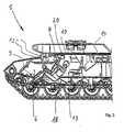
- a first space 6 is provided behind a bow-side armor 5, which is chosen so large that in it both a seat 7 for a driver 8 and parallel thereto a seat 9 for a commander 10 of Vehicle 1 are located. Both the seat 7 of the driver 8 and that of the commander 10 hatches 11 and angle mirror 12 are assigned above the seats 7, 9, so that when driving under armored protection or at the site for both the driver 8 and the commander 10 a direct View to the front is possible.
- a second space 13 is provided in the region of the dome 3 of the installation armor 1, which is directly connected to the first space 6, and in which a - in relation to the seat 9 of the commander 10 in the first room 6- elevated seat 14 for the commander 10 is located. From this seat 14, the commander 10 has a hatch 15 or via corresponding angle mirrors 16 a direct all-round view.
- connection of the two rooms 6, 13 is chosen such that the commander 10 can move his residence from the first room 6 in the second room 13 and vice versa, both while driving to the place of use and after reaching the place of use.
- Monitoring and control devices 17 are provided both in the first room 6 and in the second room 13, by means of which the commander 10 can view and operate all the operating and display elements which are important for the use (see FIG Means for the front command seat is shown).
- a seat change of the commander 10 will be explained below with reference to FIGS.
- the commander 10 is initially in the second room 13, i. in the area of the dome, and can over the angle mirror 16 monitor the trip to the site (Fig.1).
- the commander 10 leaves his seat 14 in the region of the dome 3 and moves in the direction of his seat 9 in the first space 6 (FIG.
- the backrest 18 of this seat 9 is folded down to the rear.
- 1 handles 20 are provided on the ceiling of the installation armor, where the commander 10 can hold in its forward movement.
- the invention is not limited to the embodiment described above.
- the two rooms need not be separate rooms separated by a separate opening. Rather, it can also be two subspaces of a act together (team) space.
- the driver and front command seat are in the first compartment and the rear command seat in the second compartment.
- the dome may also be provided with additional armor and the vehicle may be equipped with cameras 21 (Figure 3) to cover the area around the laying vehicle, e.g. in darkness and / or fog to monitor over monitors.
- the commander seat can also via a guide (eg a rail) manually or via a (eg electric) drive from the front to the rear and vice versa method and be fixed with a locking device.
- a guide eg a rail
- a (eg electric) drive from the front to the rear and vice versa method and be fixed with a locking device.
Landscapes
- Engineering & Computer Science (AREA)
- General Engineering & Computer Science (AREA)
- Seats For Vehicles (AREA)
- Body Structure For Vehicles (AREA)
- Vehicle Waterproofing, Decoration, And Sanitation Devices (AREA)
- Extraction Or Liquid Replacement (AREA)
- Catching Or Destruction (AREA)
- Aiming, Guidance, Guns With A Light Source, Armor, Camouflage, And Targets (AREA)
Abstract
Description
- Die Erfindung betrifft ein Verlegefahrzeug, insbesondere einen Verlegepanzer, zum Verlegen von Brückenteilen mit den im Oberbegriff des Anspruchs 1 angegebenen Merkmalen.
- Bei bekannten derartigen Verlegefahrzeugen ist in dem vorderen Bereich des Fahrzeuges ein erster Raum mit einem Sitz für einen Fahrer des Verlegefahrzeuges und in einem zweiten Raum, im Bereich eines Turmes oder Domes des Verlegefahrzeuges, ein gegenüber dem ersten Sitz erhöhter Sitz für einen Kommandanten des Fahrzeuges vorgesehen. Dabei ist der Sitz des Kommandanten in dem Dom derart angeordnet, dass er über eine gute Rundumsicht verfügt.
- Nachteilig ist bei derartigen bekannten Veriegefahrzeugen, dass der ballistische Schutz im Bereich des Domes in der Regel wesentlich geringer ist als vor dem ersten Raum, in dem sich der Fahrer befindet. Insbesondere bei durchzuführenden Brückenarbeiten an einem entsprechenden Flußufer ist der Kommandant des Verlegefahrzeuges daher einer hohen Bedrohung durch feindlichen Beschuß ausgesetzt.
- Zwar ist es denkbar, den ballistischen Schutz im Bereich des Domes durch entsprechende Verstärkung der Panzerung zu erhöhen, doch würde dieses zwangsläufig zu einem wesentlich höheren Gewicht des Verlegefahrzeuges im Bereich des Domes führen, was aus Kosten- und anderen Gründen (Änderung der Auslegung der gesamten Konstruktion des Verlegefahrzeuges und insbesondere der Fahrzeugmotoren, schlechte Verlastbarkeit etc.) unerwünscht ist.
- Der Erfindung liegt die Aufgabe zugrunde, ein Vedegefahrzeug anzugeben, bei dem einerseits der Kommandant bei der Fahrt zum Einsatzort über seinen Sitzplatz im Dom sich einen guten Überblick verschaffen und das Fahrzeug dirigieren kann und bei dem andererseits die ballistische Bedrohung des Kommandanten am Einsatzort gering ist, ohne dass es eines zusätzlichen ballistischen Schutzes des Domes bedarf.
- Diese Aufgabe wird erfindungsgemäß durch die Merkmale des Anspruchs 1 gelöst. Weitere, besonders vorteilhafte Ausgestaltungen der Erfindung offenbaren die Unteransprüche.
- Die Erfindung beruht im wesentlichen auf dem Gedanken, die Größe des ersten Raumes derart zu wählen, dass für den Kommandanten ebenfalls ein Sitzplatz neben dem Fahrer vorgesehen ist oder angeordnet werden kann, wobei der erste und der zweite Raum derart miteinander verbunden sind, dass der Kommandant im Bedarfsfalle einen entsprechenden Sitzplatzwechsel innerhalb des Verlegefahrzeuges vornehmen kann.
- Durch diesen möglichen Sitzplatzwechsel kann der Kommandant bei der Fahrt zum Einsatzort, bei dem die ballistische Bedrohung gering ist, weiterhin über den Sitzplatz im Dom das Fahrzeug dirigieren. Am Einsatzort, wo der Brückenverlegevorgang durchgeführt werden soll, kann der Kommandant dann einen Sitzplatzwechsel in den vorderen, ballistisch geschützten Bereich des Verlegefahrzeuges vornehmen und das gegenüberliegende Ufer (z.B. über eine geöffnete Luke im Dach des Verlegefahrzeuges oder über Winkelspiegel bzw. gegebenenfalls auch mittels einer Kamera) beobachten sowie den Brückenverlegevorgang überwachen.
- Bei dem zusätzlichen Sitzplatz in dem ersten Raum kann es sich um einen fest angeordneten Sitz handeln, dessen Rückenlehne umklappbar ausgebildet ist, derart, dass der Kommandant bei einem Sitzplatzwechsel durch die Rückenlehne nicht behindert wird.
- Sofern das Verlegefahrzeug mit einem Minenschutz ausgestattet ist, bei dem die Sitze durch Gurtsitzsysteme ersetzt sind, handelt es sich bei den beiden Sitzen jeweils um eine Gurtaufnahme. Der Kommandant muss sich in diesem Fall zu einem Sitzplatzwechsel zunächst mit seinem umgeschnallten Gurtsitz von der einen Gurtaufnahme lösen und sich anschließend in die zweite Gurtaufnahme einhängen.
- Anstatt einen fest angeordneten Sitz vorzusehen, kann zwischen dem ersten und zweiten Raum auch eine Führungsschiene angeordnet sein, entlang welcher der Sitz des Kommandanten von dem ersten in den zweiten Raum und umgekehrt verschiebbar ist, wobei der Sitz in seinen Endpositionen mittels einer Arretierungseinrichtung fixierbar ist.
- Vorteilhafterweise ist vorgesehen, dass sich sowohl in dem ersten wie in dem zweiten Raum Überwachungs- und Steuerungseinrichtungen befinden, mittels welcher der Kommandant alle für den Einsatz wichtigen Bedien- und Anzeigeelemente einsehen und bedienen kann.
- Weitere Einzelheiten und Vorteile der Erfindung ergeben sich aus den folgenden, anhand von Figuren erläuterten Ausführungsbeispielen. Es zeigen:
- Fig.1 den Längsschnitt durch einen Teil eines erfindungsgemäßen Verlegefahrzeuges, wobei sich der Fahrer im Bugbereich und der Kommandant im Dombereich des Fahrzeuges befinden;
- Fig.2 eine Fig.1 entsprechende Ansicht, wobei der Kommandant seinen domseitigen Platz verläßt und sich neben den Fahrer positioniert und
- Fig.3 ein Fig.1 entsprechende Ansicht, wobei der Kommandant neben dem Fahrer sitzt.
- In den Fig.1-3 ist mit 1 ein Verlegepanzer zum Verlegen von Brückenteilen bezeichnet, der ein Kettenfahrzeug 2 mit einem Dom 3 umfaßt. Der Dom 3 nimmt in an sich bekannter Weise eine Verlegeeinrichtung (nicht dargestellt) auf und ist mit einem nicht dargestellten ballistischen Grundschutz ausgestattet, der an die jeweilige Anforderung angepaßt werden kann.
- In dem vorderen Bereich des Verlegepanzers 1 ist hinter einer bugseitig angeordneten Panzerung 5 ein erster Raum 6 vorgesehen, der so groß gewählt ist, dass sich in ihm sowohl ein Sitz 7 für einen Fahrer 8 als auch parallel hierzu ein Sitz 9 für einen Kommandanten 10 des Fahrzeuges 1 befinden. Sowohl dem Sitz 7 des Fahrers 8 als auch demjenigen des Kommandanten 10 sind Luken 11 und Winkelspiegel 12 oberhalb der Sitze 7, 9 zugeordnet, so dass bei Fahrt unter Panzerschutz bzw. am Einsatzort sowohl für den Fahrer 8 als auch für den Kommandanten 10 eine direkte Sicht nach vorne möglich ist.
- Hinter dem ersten Raum 6 ist ein zweiter Raum 13 im Bereich des Domes 3 des Verlegepanzers 1 vorgesehen, der mit dem ersten Raum 6 direkt verbunden ist, und in dem sich ein -gegenüber dem Sitz 9 des Kommandanten 10 im ersten Raum 6- erhöhter Sitz 14 für den Kommandanten 10 befindet. Von diesem Sitz 14 aus hat der Kommandant 10 über eine Luke 15 bzw. über entsprechende Winkelspiegel 16 eine direkte Rundumsicht.
- Die Verbindung der beiden Räume 6, 13 ist derart gewählt, dass der Kommandant 10 seinen Aufenthalt von dem ersten Raum 6 in den zweiten Raum 13 und umgekehrt sowohl während der Fahrt zum Einsatzort als auch nach Erreichen des Einsatzortes verlegen kann.
- Sowohl in dem ersten Raum 6 als auch in dem zweiten Raum 13 sind Überwachungs- und Steuereinrichtungen 17 vorgesehen, mittels welcher der Kommandant 10 alle für den Einsatz wichtigen Bedien- und Anzeigeelemente einsehen und bedienen kann (vgl. Fig.3, in der eine derartige Einrichtung für den vorderen Kommandantensitz dargestellt ist).
- Anhand der Fig.1-3 soll nachfolgend ein Sitzplatzwechsel des Kommandanten 10 erläutert werden. Dabei befindet sich der Kommandant 10 zunächst in dem zweiten Raum 13, d.h. im Bereich des Domes, und kann über die Winkelspiegel 16 die Fahrt zum Einsatzort überwachen (Fig.1).
- Hat das Verlegefahrzeug 1 seinen Einsatzort erreicht, so verläßt der Kommandant 10 seinen Sitz 14 im Bereich des Domes 3 und bewegt sich in Richtung auf seinen Sitz 9 im ersten Raum 6 (Fig.2). Hierzu ist die Rückenlehne 18 dieses Sitzes 9 nach hinten heruntergeklappt. Außerdem sind an der Decke des Verlegepanzers 1 Griffe 20 vorgesehen, an denen der Kommandant 10 sich bei seiner Vorwärtsbewegung halten kann.
- Sobald der Kommandant 10 neben dem Fahrer 8 sitzt, klappt er die Rückenlehne 18 wieder hoch und bringt seinen Sitz 9 in die ihm am Günstigsten erscheinende Position (z.B, Änderung der Einstellung hinsichtlich der Höhe und/oder des Neigungswinkels) (Fig.3).
- Die Erfindung ist selbstverständlich nicht auf das vorstehend beschriebene Ausführungsbeispiel beschränkt. So muss es sich bei den beiden Räumen nicht um durch eine separate Öffnung getrennte Räume handeln. Vielmehr kann es sich auch um zwei Teilräume eines gemeinsamen (Mannschafts-) Raumes handeln. In diesem Fall befinden sich der Fahrer- und der vordere Kommandantensitz in dem ersten Teilraum und der hintere Kommandantensitz in dem zweiten Teilraum.
- Ferner kann auch der Dom mit einer zusätzlichen Panzerung und das Fahrzeug mit Kameras 21 (Fig.3) ausgestattet sein, um den Bereich um das Verlegefahrzeug, z.B. bei Dunkelheit und/oder Nebel, über Monitore überwachen zu können.
- Schließlich muss in dem ersten Raum nicht ständig ein zusätzlicher Sitz für den Kommandanten vorgesehen sein, sondern der Kommandantensitz kann auch über eine Führung (z.B. eine Schiene) manuell oder über einen (z.B. elektrischen) Antrieb von der vorderen in die hintere Position und umgekehrt verfahren und mit einer Arretierungseinrichtung fixiert werden.
-
- 1
- Verlegefahrzeug, Verlegepanzer, Fahrzeug
- 2
- Kettenfahrzeug
- 3
- Dom, Turm
- 5
- Panzerung
- 6
- (erster) Raum
- 7
- Sitz, Platz (Fahrer)
- 8
- Fahrer
- 9
- Sitz, Platz (Kommandant)
- 10
- Kommandant
- 11
- Luke
- 12
- Winkelspiegel
- 13
- (zweiter) Raum
- 14
- Sitz
- 15
- Luke
- 16
- Winkelspiegel
- 17
- Überwachungs- und Steuereinrichtung
- 18
- Rückenlehne
- 20
- Griff
- 21
- Kamera
Claims (7)
- Verlegefahrzeug, insbesondere Verlegepanzer, zum Verlegen von Brückenteilen, wobei in dem vorderen Bereich des Verlegefahrzeuges (1) ein erster Raum (6) mit einem Sitz (7) für einen Fahrer (8) des Verlegefahrzeuges (1) und in einem zweiten Raum (13) im Bereich eines Turmes oder Domes (3) des Verlegefahrzeuges (1) ein gegenüber dem Sitz (7) in dem ersten Raum (6) erhöhter Sitz (14) für einen Kommandanten (10) des Fahrzeuges (1) vorgesehen ist, dadurch gekennzeichnet, dass die Größe des ersten Raumes (6) derart gewählt ist, dass in diesem Raum (6) zusätzlich zu dem Sitz (7) des Fahrers (8) und parallel zu diesem auch ein Sitz für den Kommandanten (10) vorgesehen oder anordbar ist, und dass der erste Raum (6) mit dem zweiten Raum (13) derart verbunden ist, dass der Kommandant (10) seinen Aufenthalt von dem ersten Raum (6) in den zweiten Raum (13) und umgekehrt verlegen kann.
- Verlegefahrzeug nach Anspruch 1, dadurch gekennzeichnet, dass sich in dem ersten Raum (6) ein fest angeordneter Sitz (9) für den Kommandanten (10) befindet, dessen Rückenlehne (18) umklappbar ausgebildet ist, derart, dass der Kommandant (10) bei einem Sitzplatzwechsel durch die Rückenlehne (18) nicht behindert wird.
- Verlegefahrzeug nach Anspruch 2, dadurch gekennzeichnet, dass es sich bei den beiden Sitzen (7, 14) des Kommandanten (10) jeweils um eine Gurtaufnahme eines Gurtsitzsystems handelt.
- Verlegefahrzeug nach Anspruch 1, dadurch gekennzeichnet, dass zwischen dem ersten und zweiten Raum (6, 13) mindestens eine Führungsschiene angeordnet ist, entlang welcher ein Sitz des Kommandanten (10) von dem ersten in den zweiten Raum (6, 13) und umgekehrt manuell oder mittels eines motorischen Antriebes verschiebbar ist, wobei der Sitz in seinen jeweiligen Endpositionen mittels einer Arretierungseinrichtung fixierbar ist.
- Verlegefahrzeug nach einem der Ansprüche 1 bis 4, dadurch gekennzeichnet, dass sowohl in dem ersten wie in dem zweiten Raum (6, 13) Überwachungs- und Steuerungseinrichtungen (17) vorgesehen sind, mittels welcher der Kommandant (10) alle für den Einsatz wichtigen Bedien- und Anzeigeelemente einsehen und bedienen kann.
- Verlegefahrzeug nach einem der Ansprüche 1 bis 5, dadurch gekennzeichnet, dass dem Platz (9) des Kommandanten (10) in dem ersten Raum (6) eine Luke (11) zugeordnet ist.
- Verlegefiahrzeug nach einem der Ansprüche 1 bis 6, dadurch gekennzeichnet, dass dem Platz (9) des Kommandanten (10) im ersten Raum (6) Winkelspiegel (12) zugeordnet sind.
Priority Applications (1)
| Application Number | Priority Date | Filing Date | Title |
|---|---|---|---|
| PL06017510T PL1757895T3 (pl) | 2005-08-23 | 2006-08-23 | Układarka |
Applications Claiming Priority (1)
| Application Number | Priority Date | Filing Date | Title |
|---|---|---|---|
| DE102005039727A DE102005039727B4 (de) | 2005-08-23 | 2005-08-23 | Verlegefahrzeug |
Publications (2)
| Publication Number | Publication Date |
|---|---|
| EP1757895A1 true EP1757895A1 (de) | 2007-02-28 |
| EP1757895B1 EP1757895B1 (de) | 2009-03-04 |
Family
ID=37309545
Family Applications (1)
| Application Number | Title | Priority Date | Filing Date |
|---|---|---|---|
| EP06017510A Not-in-force EP1757895B1 (de) | 2005-08-23 | 2006-08-23 | Verlegefahrzeug |
Country Status (5)
| Country | Link |
|---|---|
| EP (1) | EP1757895B1 (de) |
| AT (1) | ATE424544T1 (de) |
| DE (2) | DE102005039727B4 (de) |
| ES (1) | ES2322613T3 (de) |
| PL (1) | PL1757895T3 (de) |
Cited By (2)
| Publication number | Priority date | Publication date | Assignee | Title |
|---|---|---|---|---|
| EP2719991A1 (de) * | 2012-10-15 | 2014-04-16 | Pearson Engineering Limited | Montieranordnung für ein Fahrzeug und Fahrzeug mit der Anordnung |
| RU199427U1 (ru) * | 2019-01-29 | 2020-09-01 | Акционерное общество "Омский завод транспортного машиностроения" | Танк |
Families Citing this family (1)
| Publication number | Priority date | Publication date | Assignee | Title |
|---|---|---|---|---|
| DE102022107733B4 (de) | 2022-03-31 | 2026-04-16 | Knds Deutschland Gmbh & Co. Kg | Militärisches Fahrzeug |
Citations (3)
| Publication number | Priority date | Publication date | Assignee | Title |
|---|---|---|---|---|
| DE1703221A1 (de) * | 1968-04-19 | 1971-04-15 | Porsche Kg | Kampffahrzeug mit einer Sichtkuppel |
| EP0874211A2 (de) | 1997-04-26 | 1998-10-28 | Wegmann & Co. GmbH | Kampffahrzeug |
| DE10127742A1 (de) * | 2001-06-08 | 2002-12-12 | Krauss Maffei Wegmann Gmbh & C | Schützenpanzer |
Family Cites Families (1)
| Publication number | Priority date | Publication date | Assignee | Title |
|---|---|---|---|---|
| US5067191A (en) * | 1988-11-12 | 1991-11-26 | Man Gutehoffnungshutte Ag | Bridge layer |
-
2005
- 2005-08-23 DE DE102005039727A patent/DE102005039727B4/de not_active Expired - Fee Related
-
2006
- 2006-08-23 EP EP06017510A patent/EP1757895B1/de not_active Not-in-force
- 2006-08-23 DE DE502006002994T patent/DE502006002994D1/de active Active
- 2006-08-23 ES ES06017510T patent/ES2322613T3/es active Active
- 2006-08-23 PL PL06017510T patent/PL1757895T3/pl unknown
- 2006-08-23 AT AT06017510T patent/ATE424544T1/de not_active IP Right Cessation
Patent Citations (3)
| Publication number | Priority date | Publication date | Assignee | Title |
|---|---|---|---|---|
| DE1703221A1 (de) * | 1968-04-19 | 1971-04-15 | Porsche Kg | Kampffahrzeug mit einer Sichtkuppel |
| EP0874211A2 (de) | 1997-04-26 | 1998-10-28 | Wegmann & Co. GmbH | Kampffahrzeug |
| DE10127742A1 (de) * | 2001-06-08 | 2002-12-12 | Krauss Maffei Wegmann Gmbh & C | Schützenpanzer |
Cited By (2)
| Publication number | Priority date | Publication date | Assignee | Title |
|---|---|---|---|---|
| EP2719991A1 (de) * | 2012-10-15 | 2014-04-16 | Pearson Engineering Limited | Montieranordnung für ein Fahrzeug und Fahrzeug mit der Anordnung |
| RU199427U1 (ru) * | 2019-01-29 | 2020-09-01 | Акционерное общество "Омский завод транспортного машиностроения" | Танк |
Also Published As
| Publication number | Publication date |
|---|---|
| ES2322613T3 (es) | 2009-06-23 |
| ATE424544T1 (de) | 2009-03-15 |
| DE102005039727B4 (de) | 2007-08-16 |
| DE502006002994D1 (de) | 2009-04-16 |
| EP1757895B1 (de) | 2009-03-04 |
| PL1757895T3 (pl) | 2009-08-31 |
| DE102005039727A1 (de) | 2007-03-01 |
Similar Documents
| Publication | Publication Date | Title |
|---|---|---|
| EP1499846B1 (de) | Schutzvorrichtung für gepanzerte fahrzeuge, insbesondere gegen hohlladungsgeschosse | |
| EP2773521B1 (de) | Amphibienfahrzeug und verfahren zum betrieb eines amphibienfahrzeugs | |
| EP1191303B1 (de) | Gepanzertes Fahrzeug, insbesondere Kampffahrzeug | |
| EP1832499A2 (de) | Militärisches Kraftfahrzeug zum Mannschaftstransport | |
| EP2411262A1 (de) | Knickgelenktes fahrzeug, insbesondere gepanzertes fahrzeug | |
| DE102005039727B4 (de) | Verlegefahrzeug | |
| DE102009022358B3 (de) | Lafette für eine an einem militärischen Fahrzeug angeordnete leichte Waffe sowie mit einer derartigen Lafette ausgerüstetes militärisches Fahrzeug | |
| EP1500900B1 (de) | Sichteinrichtung an einem Kampffahrzeug, insbesondere einem Kampfpanzer | |
| DE3134012A1 (de) | Aufklaerungsgeraet fuer panzerfahrzeuge | |
| DE3508660C2 (de) | Kampffahrzeug mit scheitellafettierter Waffenanlage | |
| DE10133147B4 (de) | Gepanzertes Transportfahrzeug | |
| DE3121144C2 (de) | Fahrzeug mit einer gepanzerten Wanne | |
| EP2961621B2 (de) | Schwimmmodul für ein militärisches fahrzeug | |
| DE20121851U1 (de) | Gepanzertes Transportfahrzeug mit einem Gefechtsstand | |
| DE3305883A1 (de) | Winkelspiegel fuer gepanzerte fahrzeuge, insbesondere kampfpanzer | |
| DE10255254A1 (de) | Minenräumfahrzeug | |
| DE102008034245B4 (de) | Lukendeckel zur Verwendung an einem gepanzerten Fahrzeug, insbesondere Kampffahrzeug | |
| EP2585790B1 (de) | Militärisches fahrzeuggehäuse | |
| EP1512618B1 (de) | Schiff mit modularer Struktur | |
| DE3508660C1 (de) | ||
| DE102023002546A1 (de) | Adaptiver Drahtseilschneider für Fahrzeuge mit Fahrzeugluken | |
| EP1291602A2 (de) | Schwenkbare Helmhalter für ein gepanzertes Transportfahrzeug | |
| DE102017004407B4 (de) | Vorrichtung zur Aufnahme eines elektrischen oder elektronischen Gerätes in einem Fahrzeug | |
| DE102022123983A1 (de) | Mittelführerhauslokomotive mit einem Führerhaus und wenigstens einem innerhalb des Führerhauses angeordneten elektrischen Schaltschrank | |
| DE10133143A1 (de) | Gepanzertes Transportfahrzeug mit einem Gefechtsstand |
Legal Events
| Date | Code | Title | Description |
|---|---|---|---|
| PUAI | Public reference made under article 153(3) epc to a published international application that has entered the european phase |
Free format text: ORIGINAL CODE: 0009012 |
|
| AK | Designated contracting states |
Kind code of ref document: A1 Designated state(s): AT BE BG CH CY CZ DE DK EE ES FI FR GB GR HU IE IS IT LI LT LU LV MC NL PL PT RO SE SI SK TR |
|
| AX | Request for extension of the european patent |
Extension state: AL BA HR MK YU |
|
| 17P | Request for examination filed |
Effective date: 20070706 |
|
| 17Q | First examination report despatched |
Effective date: 20070806 |
|
| AKX | Designation fees paid |
Designated state(s): AT BE BG CH CY CZ DE DK EE ES FI FR GB GR HU IE IS IT LI LT LU LV MC NL PL PT RO SE SI SK TR |
|
| GRAP | Despatch of communication of intention to grant a patent |
Free format text: ORIGINAL CODE: EPIDOSNIGR1 |
|
| GRAS | Grant fee paid |
Free format text: ORIGINAL CODE: EPIDOSNIGR3 |
|
| GRAA | (expected) grant |
Free format text: ORIGINAL CODE: 0009210 |
|
| AK | Designated contracting states |
Kind code of ref document: B1 Designated state(s): AT BE BG CH CY CZ DE DK EE ES FI FR GB GR HU IE IS IT LI LT LU LV MC NL PL PT RO SE SI SK TR |
|
| REG | Reference to a national code |
Ref country code: GB Ref legal event code: FG4D Free format text: NOT ENGLISH |
|
| REG | Reference to a national code |
Ref country code: CH Ref legal event code: EP |
|
| REG | Reference to a national code |
Ref country code: IE Ref legal event code: FG4D Free format text: LANGUAGE OF EP DOCUMENT: GERMAN |
|
| REG | Reference to a national code |
Ref country code: CH Ref legal event code: NV Representative=s name: OK PAT AG PATENTE MARKEN LIZENZEN |
|
| REF | Corresponds to: |
Ref document number: 502006002994 Country of ref document: DE Date of ref document: 20090416 Kind code of ref document: P |
|
| REG | Reference to a national code |
Ref country code: SE Ref legal event code: TRGR |
|
| REG | Reference to a national code |
Ref country code: ES Ref legal event code: FG2A Ref document number: 2322613 Country of ref document: ES Kind code of ref document: T3 |
|
| PG25 | Lapsed in a contracting state [announced via postgrant information from national office to epo] |
Ref country code: SI Free format text: LAPSE BECAUSE OF FAILURE TO SUBMIT A TRANSLATION OF THE DESCRIPTION OR TO PAY THE FEE WITHIN THE PRESCRIBED TIME-LIMIT Effective date: 20090304 Ref country code: LT Free format text: LAPSE BECAUSE OF FAILURE TO SUBMIT A TRANSLATION OF THE DESCRIPTION OR TO PAY THE FEE WITHIN THE PRESCRIBED TIME-LIMIT Effective date: 20090304 |
|
| PG25 | Lapsed in a contracting state [announced via postgrant information from national office to epo] |
Ref country code: LV Free format text: LAPSE BECAUSE OF FAILURE TO SUBMIT A TRANSLATION OF THE DESCRIPTION OR TO PAY THE FEE WITHIN THE PRESCRIBED TIME-LIMIT Effective date: 20090304 |
|
| REG | Reference to a national code |
Ref country code: PL Ref legal event code: T3 |
|
| REG | Reference to a national code |
Ref country code: IE Ref legal event code: FD4D |
|
| PG25 | Lapsed in a contracting state [announced via postgrant information from national office to epo] |
Ref country code: IE Free format text: LAPSE BECAUSE OF FAILURE TO SUBMIT A TRANSLATION OF THE DESCRIPTION OR TO PAY THE FEE WITHIN THE PRESCRIBED TIME-LIMIT Effective date: 20090304 Ref country code: CZ Free format text: LAPSE BECAUSE OF FAILURE TO SUBMIT A TRANSLATION OF THE DESCRIPTION OR TO PAY THE FEE WITHIN THE PRESCRIBED TIME-LIMIT Effective date: 20090304 Ref country code: EE Free format text: LAPSE BECAUSE OF FAILURE TO SUBMIT A TRANSLATION OF THE DESCRIPTION OR TO PAY THE FEE WITHIN THE PRESCRIBED TIME-LIMIT Effective date: 20090304 Ref country code: PT Free format text: LAPSE BECAUSE OF FAILURE TO SUBMIT A TRANSLATION OF THE DESCRIPTION OR TO PAY THE FEE WITHIN THE PRESCRIBED TIME-LIMIT Effective date: 20090818 |
|
| PG25 | Lapsed in a contracting state [announced via postgrant information from national office to epo] |
Ref country code: SK Free format text: LAPSE BECAUSE OF FAILURE TO SUBMIT A TRANSLATION OF THE DESCRIPTION OR TO PAY THE FEE WITHIN THE PRESCRIBED TIME-LIMIT Effective date: 20090304 Ref country code: RO Free format text: LAPSE BECAUSE OF FAILURE TO SUBMIT A TRANSLATION OF THE DESCRIPTION OR TO PAY THE FEE WITHIN THE PRESCRIBED TIME-LIMIT Effective date: 20090304 Ref country code: IS Free format text: LAPSE BECAUSE OF FAILURE TO SUBMIT A TRANSLATION OF THE DESCRIPTION OR TO PAY THE FEE WITHIN THE PRESCRIBED TIME-LIMIT Effective date: 20090704 |
|
| PLBE | No opposition filed within time limit |
Free format text: ORIGINAL CODE: 0009261 |
|
| STAA | Information on the status of an ep patent application or granted ep patent |
Free format text: STATUS: NO OPPOSITION FILED WITHIN TIME LIMIT |
|
| PG25 | Lapsed in a contracting state [announced via postgrant information from national office to epo] |
Ref country code: DK Free format text: LAPSE BECAUSE OF FAILURE TO SUBMIT A TRANSLATION OF THE DESCRIPTION OR TO PAY THE FEE WITHIN THE PRESCRIBED TIME-LIMIT Effective date: 20090304 Ref country code: BG Free format text: LAPSE BECAUSE OF FAILURE TO SUBMIT A TRANSLATION OF THE DESCRIPTION OR TO PAY THE FEE WITHIN THE PRESCRIBED TIME-LIMIT Effective date: 20090604 |
|
| 26N | No opposition filed |
Effective date: 20091207 |
|
| BERE | Be: lapsed |
Owner name: RHEINMETALL LANDSYSTEME G.M.B.H. Effective date: 20090831 |
|
| PG25 | Lapsed in a contracting state [announced via postgrant information from national office to epo] |
Ref country code: MC Free format text: LAPSE BECAUSE OF NON-PAYMENT OF DUE FEES Effective date: 20090831 |
|
| PG25 | Lapsed in a contracting state [announced via postgrant information from national office to epo] |
Ref country code: BE Free format text: LAPSE BECAUSE OF NON-PAYMENT OF DUE FEES Effective date: 20090831 |
|
| PG25 | Lapsed in a contracting state [announced via postgrant information from national office to epo] |
Ref country code: GR Free format text: LAPSE BECAUSE OF FAILURE TO SUBMIT A TRANSLATION OF THE DESCRIPTION OR TO PAY THE FEE WITHIN THE PRESCRIBED TIME-LIMIT Effective date: 20090605 |
|
| PGFP | Annual fee paid to national office [announced via postgrant information from national office to epo] |
Ref country code: NL Payment date: 20100813 Year of fee payment: 5 |
|
| PG25 | Lapsed in a contracting state [announced via postgrant information from national office to epo] |
Ref country code: AT Free format text: LAPSE BECAUSE OF NON-PAYMENT OF DUE FEES Effective date: 20090823 |
|
| PGFP | Annual fee paid to national office [announced via postgrant information from national office to epo] |
Ref country code: FI Payment date: 20100812 Year of fee payment: 5 |
|
| PG25 | Lapsed in a contracting state [announced via postgrant information from national office to epo] |
Ref country code: IT Free format text: LAPSE BECAUSE OF FAILURE TO SUBMIT A TRANSLATION OF THE DESCRIPTION OR TO PAY THE FEE WITHIN THE PRESCRIBED TIME-LIMIT Effective date: 20090304 |
|
| GBPC | Gb: european patent ceased through non-payment of renewal fee |
Effective date: 20100823 |
|
| PG25 | Lapsed in a contracting state [announced via postgrant information from national office to epo] |
Ref country code: LU Free format text: LAPSE BECAUSE OF NON-PAYMENT OF DUE FEES Effective date: 20090823 |
|
| PG25 | Lapsed in a contracting state [announced via postgrant information from national office to epo] |
Ref country code: HU Free format text: LAPSE BECAUSE OF FAILURE TO SUBMIT A TRANSLATION OF THE DESCRIPTION OR TO PAY THE FEE WITHIN THE PRESCRIBED TIME-LIMIT Effective date: 20090905 |
|
| PG25 | Lapsed in a contracting state [announced via postgrant information from national office to epo] |
Ref country code: GB Free format text: LAPSE BECAUSE OF NON-PAYMENT OF DUE FEES Effective date: 20100823 Ref country code: TR Free format text: LAPSE BECAUSE OF FAILURE TO SUBMIT A TRANSLATION OF THE DESCRIPTION OR TO PAY THE FEE WITHIN THE PRESCRIBED TIME-LIMIT Effective date: 20090304 |
|
| PG25 | Lapsed in a contracting state [announced via postgrant information from national office to epo] |
Ref country code: CY Free format text: LAPSE BECAUSE OF FAILURE TO SUBMIT A TRANSLATION OF THE DESCRIPTION OR TO PAY THE FEE WITHIN THE PRESCRIBED TIME-LIMIT Effective date: 20090304 |
|
| REG | Reference to a national code |
Ref country code: NL Ref legal event code: V1 Effective date: 20120301 |
|
| PG25 | Lapsed in a contracting state [announced via postgrant information from national office to epo] |
Ref country code: FI Free format text: LAPSE BECAUSE OF NON-PAYMENT OF DUE FEES Effective date: 20110823 Ref country code: NL Free format text: LAPSE BECAUSE OF NON-PAYMENT OF DUE FEES Effective date: 20120301 |
|
| REG | Reference to a national code |
Ref country code: FR Ref legal event code: PLFP Year of fee payment: 11 |
|
| PGFP | Annual fee paid to national office [announced via postgrant information from national office to epo] |
Ref country code: DE Payment date: 20160822 Year of fee payment: 11 Ref country code: CH Payment date: 20160819 Year of fee payment: 11 |
|
| PGFP | Annual fee paid to national office [announced via postgrant information from national office to epo] |
Ref country code: PL Payment date: 20160722 Year of fee payment: 11 Ref country code: FR Payment date: 20160822 Year of fee payment: 11 Ref country code: SE Payment date: 20160819 Year of fee payment: 11 |
|
| PGFP | Annual fee paid to national office [announced via postgrant information from national office to epo] |
Ref country code: ES Payment date: 20160810 Year of fee payment: 11 |
|
| REG | Reference to a national code |
Ref country code: DE Ref legal event code: R119 Ref document number: 502006002994 Country of ref document: DE |
|
| REG | Reference to a national code |
Ref country code: CH Ref legal event code: PL |
|
| PG25 | Lapsed in a contracting state [announced via postgrant information from national office to epo] |
Ref country code: LI Free format text: LAPSE BECAUSE OF NON-PAYMENT OF DUE FEES Effective date: 20170831 Ref country code: CH Free format text: LAPSE BECAUSE OF NON-PAYMENT OF DUE FEES Effective date: 20170831 Ref country code: SE Free format text: LAPSE BECAUSE OF NON-PAYMENT OF DUE FEES Effective date: 20170824 |
|
| REG | Reference to a national code |
Ref country code: FR Ref legal event code: ST Effective date: 20180430 |
|
| PG25 | Lapsed in a contracting state [announced via postgrant information from national office to epo] |
Ref country code: DE Free format text: LAPSE BECAUSE OF NON-PAYMENT OF DUE FEES Effective date: 20180301 |
|
| PG25 | Lapsed in a contracting state [announced via postgrant information from national office to epo] |
Ref country code: FR Free format text: LAPSE BECAUSE OF NON-PAYMENT OF DUE FEES Effective date: 20170831 |
|
| REG | Reference to a national code |
Ref country code: ES Ref legal event code: FD2A Effective date: 20181029 |
|
| PG25 | Lapsed in a contracting state [announced via postgrant information from national office to epo] |
Ref country code: ES Free format text: LAPSE BECAUSE OF NON-PAYMENT OF DUE FEES Effective date: 20170824 |
|
| PG25 | Lapsed in a contracting state [announced via postgrant information from national office to epo] |
Ref country code: PL Free format text: LAPSE BECAUSE OF NON-PAYMENT OF DUE FEES Effective date: 20170823 |