EP1755031A2 - Verfahren und Vorrichtung zur Informationsverarbeitung - Google Patents
Verfahren und Vorrichtung zur Informationsverarbeitung Download PDFInfo
- Publication number
- EP1755031A2 EP1755031A2 EP06254105A EP06254105A EP1755031A2 EP 1755031 A2 EP1755031 A2 EP 1755031A2 EP 06254105 A EP06254105 A EP 06254105A EP 06254105 A EP06254105 A EP 06254105A EP 1755031 A2 EP1755031 A2 EP 1755031A2
- Authority
- EP
- European Patent Office
- Prior art keywords
- information
- printer
- acquiring
- utility
- schema
- Prior art date
- Legal status (The legal status is an assumption and is not a legal conclusion. Google has not performed a legal analysis and makes no representation as to the accuracy of the status listed.)
- Withdrawn
Links
Images














Classifications
-
- G—PHYSICS
- G06—COMPUTING OR CALCULATING; COUNTING
- G06F—ELECTRIC DIGITAL DATA PROCESSING
- G06F3/00—Input arrangements for transferring data to be processed into a form capable of being handled by the computer; Output arrangements for transferring data from processing unit to output unit, e.g. interface arrangements
- G06F3/12—Digital output to print unit, e.g. line printer, chain printer
- G06F3/1201—Dedicated interfaces to print systems
- G06F3/1202—Dedicated interfaces to print systems specifically adapted to achieve a particular effect
- G06F3/1203—Improving or facilitating administration, e.g. print management
- G06F3/1207—Improving or facilitating administration, e.g. print management resulting in the user being informed about print result after a job submission
-
- G—PHYSICS
- G06—COMPUTING OR CALCULATING; COUNTING
- G06F—ELECTRIC DIGITAL DATA PROCESSING
- G06F3/00—Input arrangements for transferring data to be processed into a form capable of being handled by the computer; Output arrangements for transferring data from processing unit to output unit, e.g. interface arrangements
- G06F3/12—Digital output to print unit, e.g. line printer, chain printer
- G06F3/1201—Dedicated interfaces to print systems
- G06F3/1202—Dedicated interfaces to print systems specifically adapted to achieve a particular effect
- G06F3/1218—Reducing or saving of used resources, e.g. avoiding waste of consumables or improving usage of hardware resources
- G06F3/1219—Reducing or saving of used resources, e.g. avoiding waste of consumables or improving usage of hardware resources with regard to consumables, e.g. ink, toner, paper
-
- G—PHYSICS
- G06—COMPUTING OR CALCULATING; COUNTING
- G06F—ELECTRIC DIGITAL DATA PROCESSING
- G06F3/00—Input arrangements for transferring data to be processed into a form capable of being handled by the computer; Output arrangements for transferring data from processing unit to output unit, e.g. interface arrangements
- G06F3/12—Digital output to print unit, e.g. line printer, chain printer
- G06F3/1201—Dedicated interfaces to print systems
- G06F3/1202—Dedicated interfaces to print systems specifically adapted to achieve a particular effect
- G06F3/1218—Reducing or saving of used resources, e.g. avoiding waste of consumables or improving usage of hardware resources
- G06F3/122—Reducing or saving of used resources, e.g. avoiding waste of consumables or improving usage of hardware resources with regard to computing resources, e.g. memory, CPU
-
- G—PHYSICS
- G06—COMPUTING OR CALCULATING; COUNTING
- G06F—ELECTRIC DIGITAL DATA PROCESSING
- G06F3/00—Input arrangements for transferring data to be processed into a form capable of being handled by the computer; Output arrangements for transferring data from processing unit to output unit, e.g. interface arrangements
- G06F3/12—Digital output to print unit, e.g. line printer, chain printer
- G06F3/1201—Dedicated interfaces to print systems
- G06F3/1223—Dedicated interfaces to print systems specifically adapted to use a particular technique
- G06F3/1229—Printer resources management or printer maintenance, e.g. device status, power levels
-
- G—PHYSICS
- G06—COMPUTING OR CALCULATING; COUNTING
- G06F—ELECTRIC DIGITAL DATA PROCESSING
- G06F3/00—Input arrangements for transferring data to be processed into a form capable of being handled by the computer; Output arrangements for transferring data from processing unit to output unit, e.g. interface arrangements
- G06F3/12—Digital output to print unit, e.g. line printer, chain printer
- G06F3/1201—Dedicated interfaces to print systems
- G06F3/1223—Dedicated interfaces to print systems specifically adapted to use a particular technique
- G06F3/1237—Print job management
- G06F3/126—Job scheduling, e.g. queuing, determine appropriate device
-
- G—PHYSICS
- G06—COMPUTING OR CALCULATING; COUNTING
- G06F—ELECTRIC DIGITAL DATA PROCESSING
- G06F3/00—Input arrangements for transferring data to be processed into a form capable of being handled by the computer; Output arrangements for transferring data from processing unit to output unit, e.g. interface arrangements
- G06F3/12—Digital output to print unit, e.g. line printer, chain printer
- G06F3/1201—Dedicated interfaces to print systems
- G06F3/1278—Dedicated interfaces to print systems specifically adapted to adopt a particular infrastructure
- G06F3/1285—Remote printer device, e.g. being remote from client or server
- G06F3/1288—Remote printer device, e.g. being remote from client or server in client-server-printer device configuration
Definitions
- the present invention relates to a technology for acquiring information from a peripheral device.
- peripheral devices such as printers and scanners are used in offices, at home, and in public facilities.
- various kinds and types of utilities that help a user who utilizes the peripheral device have been developed and put into practical use.
- a utility utilized in an ink jet printer a utility that can browse information related to an ink cartridge installed to a printing apparatus body and a state of a printing job input to the printing apparatus by a client computer is known.
- MIB Management Information Base
- Bidi Communications Schema (BCS), which is made public at a website of the Microsoft Developer Network (MSDN) at "http://msdn.microsoft.com/library/default.asp”.
- MSDN Microsoft Developer Network
- Bidi Communications Schema is sometimes referred to as a Bidi Schema in the description below.
- Fig. 31 is a diagram illustrating a configuration of a conventional example describing a schema and a value used in enumerating information and a state of ink, an operation status, hardware information, paper feed unit information, and paper discharge unit information by using the schema.
- the schema is specified from the utility so as to call an IBidiSpl::SendRecv () function.
- the schema that is specified includes " ⁇ Printer.InkInfo”, “ ⁇ Printer.StatusInfo”, “ ⁇ Printer.HardwareInfo”, “ ⁇ Printer. InputBinsInfo”, and “ ⁇ Printer.OutputBinsInfo”.
- each ink name describes "CI-B Black”, “CI-C Cyan”, “CI-M Magenta”, and”CI-Y Yellow", respectively.
- Fig. 31 shows that the operation state is "Online” and in a "Standby” mode, that the size of a memory installed to the printer is 2 MB, that an auto sheet feeder named “ASF-1” is installed to the printer as the paper feed unit, and that a tray named “Tray-1” is installed to the printer as the paper discharge unit.
- the utility enumerates various kinds of information by using the schema so as to obtain all the detailed information on the printer that is described by the schema.
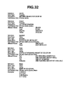
- Fig. 32 describes schemata of a conventional example that are used when the utility acquires the information concerning the ink and the state of the ink from the printer. More specifically, the schemata are specified as arguments in the call of an application program interface (API) function "IBidiSpl::SendRecv()" of a COM interface "IBidiSpl” used in the Windows (registered trademark) XP OS when the utility acquires the information concerning the ink and the state of the ink from the printer via printing and print spooler interfaces (hereinafter sometimes referred to as "PPSI").
- API application program interface
- "InkInfo” has a node type “Property” and indicates information concerning ink.
- the full path to the "InkInfo” in the schema is “ ⁇ Printer.InkInfo”.
- "[Color]” has the node type “Property” and indicates information concerning color.
- the full path to the "[Color]” in the schema is “ ⁇ Printer. InkInfo. [Color]”. Allowed values are "Black” indicating black, "Cyan” indicating cyan, "Magenta” indicating magenta, and "Yellow” indicating yellow.
- State has the node type “Value” and a data type “String”, and indicates the states of the remaining amount of the [Color] ink.
- the full path to the "State” in the schema is " ⁇ Printer.InkInfo.[Color]:State”. Allowed values are "Full” indicating that the [Color] ink is full, “Low” indicating that the remaining amount of the [Color] ink is low, “Out” indicating that the [Color] ink is out, and "Unknown” indicating that the remaining amount of the [Color] ink is unknown.
- Name has the node type "Value” and a data type "String”, and indicates the name of the [Color] ink.
- the full path to the "Name” in the schema is " ⁇ Printer.InkInfo. [Color] :Name”.
- Fig. 33 describes schemata of a conventional example that are used when the utility acquires the information concerning the paper discharge unit from the printer.
- the schemata are specified as arguments in the call of the API function "IBidiSpl::SendRecv()" of the COM interface "IBidiSpl” used in the Windows (registered trademark) XP OS when the utility acquires the information concerning the paper discharge unit from the printer via the printing and print spooler interfaces.
- OutputBinsInfo has a node type "Property” and indicates information concerning the paper discharge unit.
- the full path to the "OutputBinsInfo” in the schema is “ ⁇ Printer.OutputBinsInfo”.
- [Type] has the node type "Property” and indicates the type of the paper discharge unit.
- the full path to the "[Type]” in the schema is " ⁇ Printer.OutputBinsInfo.[Type]”.
- An allowed value is "Tray” indicating a tray.
- an information processing method as specified in claims 1 to 5.
- an information processing apparatus as specified in claims 6 to 10.
- a computer program and computer readable storage medium as specified in claims 11 and 12.
- Fig. 1 is a diagram illustrating an example of an outline of a printing system.
- Fig. 2 is a block diagram illustrating an example of a hardware configuration of a common information processing apparatus.
- Fig. 3 is a block diagram illustrating an example of a hardware configuration of a peripheral device.
- Fig. 4 is a diagram illustrating an example of a block diagram of a software module that operates on the information processing apparatus.
- Fig. 5 is a diagram illustrating a flow of a processing in the printing system.
- Fig. 6 is a flow chart of a notification service processing performed by a monitoring unit.
- Fig. 7 is a flow chart of a notification service processing performed by the monitoring unit.
- Fig. 8 is a flow chart illustrating a conversion processing according to a schema definition.
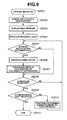
- Fig. 9 is a flow chart illustrating a processing for obtaining printer information performed by a utility.
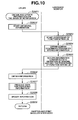
- Fig. 10 is a flow chart illustrating a processing for obtaining printer information performed by the utility.
- Fig. 11 is a flow chart illustrating the processing for producing data for displaying information.
- Fig. 12 is a diagram illustrating an appearance of a user interface of the utility.
- Fig. 13 is a diagram illustrating the schemata that are used when the utility acquires information and a state of ink loaded in a printer.
- Fig. 14 is a diagram illustrating the schemata that are used when the utility acquires hardware information of the printer.
- Fig. 15 is a diagram illustrating the schemata that are used when the utility acquires information concerning a paper feed unit of the printer.
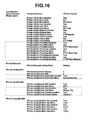
- Fig. 16 is a diagram illustrating an example of schemata and values when the information of the printer is enumerated.
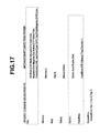
- Fig. 17 is a diagram illustrating data sent and received between a PC and the printer.
- Fig. 18 is a diagram illustrating an appearance of a user interface of the utility.
- Fig. 19 is a diagram illustrating schemata that are used when the utility acquires information of a paper feed unit of the printer.
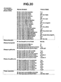
- Fig. 20 is a diagram illustrating an example of schemata and values when the information of the printer is enumerated.
- Fig. 21 is a diagram illustrating data sent and received between the PC and the printer.
- Fig. 22 is a diagram illustrating an appearance of a user interface of the utility.
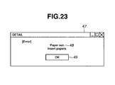
- Fig. 23 is a diagram illustrating an example of a detailed information dialog box.
- Fig. 24 is a diagram illustrating schemata that are used when the utility acquires an operation state of the printer.
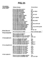
- Fig. 25 is a diagram illustrating an example of schemata and values when the information of the printer is enumerated.
- Fig. 26 is a diagram illustrating data sent and received between the PC and the printer.
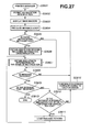
- Fig. 27 is a flow chart of a processing for obtaining printer information performed by the utility.
- Fig. 28 is a diagram illustrating an outline of another printing system.
- Fig. 29 is a diagram illustrating an outline of another printing system.
- Fig. 30 is a flow chart of a processing for obtaining printer information performed by the utility.
- Fig. 31 is a diagram illustrating an example of schemata and values when the information of the printer is enumerated according to a conventional example.
- Fig. 32 is a diagram illustrating a known example of schemata that are used when the utility acquires the printer information according to the conventional example.
- Fig. 33 is a diagram illustrating a known example of schemata that are used when the utility acquires the printer information according to the conventional example.
- Fig. 1 shows an outline of a printing system according to a first embodiment of the present invention.
- an information processing apparatus 1 hereinafter referred to as a "PC 1”
- an information processing apparatus 2 hereinafter referred to as a "PC 2”
- a printer 3 are communicably connected via a given communication channel.
- the printing system is provided with a principal software module.
- the PC 1 and the PC 2 are respectively configured by hardware that is the same as the hardware of a common information processing apparatus, and are respectively installed with a given operating system (hereinafter referred to as an "OS").
- OS operating system
- the Windows (registered trademark) XP of Microsoft Corporation of the U.S. is installed.
- the PC 1 and the PC 2 are mutually connected via a network 4 that is configured by Ethernet (registered trademark), and are allowed to perform two-way communication.
- the printer 3 is a representative example of a peripheral device.
- a color ink jet printer is connected to the PC 1 via a universal serial bus (hereinafter referred to as a "USB").
- USB universal serial bus
- a language monitor 36 (hereinafter referred to as an "LM 36") makes an inquiry to the printer 3 and outputs various kinds of commands.
- the LM 36 has a function for acquiring various kinds of information positively sent and notified from the printer 3. With this function, the LM 36 registers an event to the printer 3 in advance at a certain appropriate timing so as to implement the positive notification.
- a duplex unit 5 is an example of an option of the printer 3.
- the printer 3 is installed with the duplex unit 5 so as to perform an automatic duplex printing.
- a bookmaking component 6 is another example of the option of the printer 3.
- the printer 3 is installed with a bookmaking component 6 so as to perform a bookmaking processing.
- a utility 30 is provided with a function for acquiring and displaying various kinds of information of the printing apparatus via the LM 36, and/or outputting various kinds of commands to the printing apparatus, and/or producing and outputting print data.
- the utility 30 may be a utility for various purposes.
- the color ink jet printer is referred to as a representative example of the peripheral device.
- another form of application can be thought of. That is, there are other peripheral devices that can be applied in this embodiment. Namely, a copying machine, a facsimile, a scanner, a multifunction peripheral, a digital still camera, a digital video camera, a cellular phone, a television set, and an optical projector can be applied in this embodiment.
- Fig. 2 is a block diagram illustrating an example of a hardware configuration of a common information processing apparatus.
- a CPU 1204 is configured by a microprocessor and the like.
- the CPU 1204 implements a program that is stored in a hard disc drive (HDD) 1202.
- the CPU 1204 controls each device (each block) that is connected to a system bus 1206.
- a RAM 1201 functions as a main memory and a work area of the CPU 1204.
- a keyboard (KBD) 1203 is an example of an input instruction device for inputting various kinds of information.
- a mouse a liquid crystal touch panel, for example, can be applied.
- An LCD 1205 is an example of a display device.
- the LCD 1205 displays characters, graphic images, still images, and moving images, under control of the CPU 1204.
- An NB 1207 is a network board, which is an example of a communication control unit. The NB 1207 can control the communication according to various kinds of protocol.
- a program code for allowing a computer to implement the processing related to each step of each flow chart to be described later is stored in the HDD 1202.
- the program code is read to the RAM 1201 so as to be executed by the CPU 1204.
- Fig. 3 is a block diagram illustrating a representative example of the hardware configuration of the peripheral device.
- a CPU 15 is configured by a microprocessor and the like.
- the CPU 15 is a central processing unit of the printer 3, and performs various kinds of processing in accordance with a program stored in a ROM 16.
- the CPU 15 controls over each device such as a RAM 17, a communication unit 18, and a recording unit 19, which are mutually connected via a system bus.
- the ROM 16 may be a memory that includes a nonvolatile storage element.
- a hard disk device or an electrically-erasable flash memory may be used in substitution to the ROM 16.
- the ROM 16 stores the program for allowing the printer 3 to perform a recording (printing) processing according to input print data. In addition, the ROM 16 stores the program for performing a processing for sending information of a state upon request of the status by the PC 1.
- the RAM 17 stores print data sent from the PC 1, for example.
- the communication unit 18 includes a communication port for a USB interface 9, and controls the communication based on the USB.
- the recording unit 19 is configured by a recording section and an electric circuit.
- the recording section includes an ink jet type recording head, each color ink, a carriage, and a recording paper conveying mechanism.
- the electric circuit includes an ASIC for allowing the recording head to generate a pulsation for printing according to the print data.
- the recording unit 19 performs the recording according to the print data that the RAM 17 temporarily stores.
- the peripheral device including an ink jet type output engine is referred to as an example.
- another type output engine may be applied.
- an electrophotographic system output engine or a thermal transfer system output engine can be applied.
- a liquid crystal driving engine that drives a liquid crystal display panel can be applied.
- Fig. 4 is a diagram illustrating an example of a block diagram of a software module that operates on the PC 1, which is the information processing apparatus.
- a printer driver 50 produces a rendering command according to various application data operating on the OS.
- various kinds of formats can be applied, as long as the format of the rendering command can be decoded and read by the printer.
- the rendering command may be in the form of a non-compressed image, a compressed image, a page description language, or XML data.
- various kinds of application software can be applied. For example Word of Microsoft Corporation, Excel of Microsoft Corporation, and Photoshop of Adobe Systems, Inc. may be used.
- the utility 30 is as described with reference to Fig. 1.
- Notepad (Notepad. exe), which is a text editor supplied with Windows (registered trademark) XP OS as standard, can be applied.
- a graphics device interface (GDI) 31 constitutes a part of the OS.
- a printer queue 32 constitutes a part of a spooler 40.
- the printer queue 32 queues print jobs.
- the print jobs that are in the printer queue 32 are displayed in a printer queue folder (a description of the printer queue is omitted here) by the OS, so that a user can confirm various kinds of states of the print job.
- a print processor 33 changes a print layout and performs special processing of a print image.
- a graphics driver 34 is a core portion for image processing by the printer driver. That is, the graphics driver 34 performs processing of an image for printing according to the rendering command sent from the GDI 31 and produces a print control command.
- a UI module 35 provides and controls a user interface of the printer driver.
- the LM 36 is as described with reference to Fig. 1.
- the LM 36 has a function for controlling sending and receiving of data as a communication interface of the data.
- a port monitor 37 performs processing for sending the data sent from the LM 36 to an appropriate port and processing for receiving the data sent from the printer 3 via a class driver 38.
- the class driver 38 is a control module that is close to a physical layer.
- the class driver 38 is equivalent to a USB printer class driver, for example.
- the class driver 38 controls USB ports.
- Fig. 5 describes the processing flow for a case where the duplex unit 5 is installed to the printer 3 in the system as described with reference to Fig. 1, as an example.
- the duplex unit 5 is installed to the printer 3 (step S1).
- the printer 3 using a determination unit provided to the printer 3, determines that the duplex unit 5 is installed to the printer 3 (step S2).
- the PC 1 issues a request command requesting various kinds of information of the printing apparatus to the printer 3 via the USB interface (step S3).
- the printer 3 returns the information of the printer to the PC 1 via a communication medium, in response to the request command issued from the PC 1 (step S4).
- the information requested from the LM 36 includes printer information and job information.
- the printer information includes, for example, a type of the ink that is loaded to the printer 3, information on the option currently installed to the printer 3, state of errors of in the printer 3, and state of power.
- the job information includes state of progress of the print job input to the printer 3.
- the LM 36 acquires the information returned from the printer 3 and analyses the acquired information.
- the LM 36 determines whether there is a change in the information that has been previously acquired and stored, in accordance with a result of the analysis. If it is determined that there is a change, the LM 36 converts the information of the state after the change into a schema in accordance with a definition of schema. Then, the LM 36 stores the converted information to a storage unit (step S5).
- the processing in step S5 is equivalent to the processing of converting and retaining the information in a format for responding to a request for obtaining the information indicating the change issued from the utility.
- the term "schema" generally means a data base description that utilizes a definition language.
- the schema includes, as a representative example, an XML schema.
- the LM 36 issues a notification of a route of the schema to the utility 30 (printer manager), as shown in step S2404 in Fig. 7 (step S6).
- the notification is performed via the OS, for example.
- the route of the schema refers to the information with which the LM 36 can identify data of the schema that the LM 36 stores.
- the information using a mark " ⁇ " with which a hierarchy is specified can be applied.
- an address of the schema data that is stored as the method of describing the route or a pointer may be used.
- the utility 30 (printer manager) monitors whether there is a notification.
- the utility 30 determines that there is a notification interruption via the OS (step S7).
- the utility 30 acquires the schema route that is notified, as shown in step S2506 in Fig. 9.
- the schema route is the information concerning the notification.
- the schemata are specified as arguments in the call of an application program interface (API) function "IBidiSpl::SendRecv()" of a COM interface "IBidiSpl".
- API application program interface
- the utility 30 starts a process for enumerating and acquiring information and a state of ink, an operation status, hardware information, paper feed unit information, paper discharge unit information, system information, and unknown information that is to be newly defined in the future. After the processing is started, the utility 30 issues a request for detailed information using the schema to the LM 36 (step S8).
- the utility 30 acquires (loads) the schema data that describes the detailed information of the schema specified as the argument in step S2602 from among information stored in the form of the schema definition in step S2403 in Fig. 7 (step S9).
- step S2605 in Fig. 10 the LM 36 returns to the utility 30 (printer manager) the detailed information (schema data) that is acquired in step S9 as the argument of the "SendRecvBidiDataFromPort()" function of the LM 36 and converted into the schema definition (step S10).
- the utility 30 acquires the detailed information (schema data) that is returned in the form of the schema definition, produces data for displaying information as shown in Fig. 11, and updates a display appearance of the user interface by using the data for displaying information that is thus displayed (step S11).
- Fig. 6 is a flow chart of a notification service process performed by the language monitor (LM 36).
- the LM 36 is loaded and starts the notification service (step S2301). Then, the LM 36 acquires information returned from the printer 3 in accordance with a request command (information request) or a registration of an event to the printer 3, via a communication channel (USB cable) (step S2302). For the command that the LM 36 issues to the printer 3 at this time, a command that complies with a command specification that is uniquely defined depending on a manufacturer of the OS can be applied, for example. Then, the LM 36 stores the acquired information (step S2303). The LM 36 then determines whether there is a change in the information from the information that is previously stored (step S2304).
- the LM 36 sends the changed information to the utility 30 as an argument, and then performs the process of notification to the utility 30 (printer manager) (step S2305).
- the process performed here is equivalent to a process that is performed in relation to the changed information. Then, after that, the process waits for a given period of time (for example, for five seconds) (step S2306), and the process returns to step S2302.
- step S2304 determines that there is no change in the information from the previously-stored information. If in step S2304 it is determined that there is no change in the information from the previously-stored information, the process proceeds to step S2306, then waits for the given period of time, and then the process returns to step S2303, as described above.
- the LM 36 performs a unique notification service of acquiring the information from the printer 3 at a given interval and issuing, if there is a change in the information, a notification to the utility 30 (printer manager), so that the change in the state of the printer 3 can be notified to the utility 30 (printer manager) at an approximately real time.
- Fig. 7 is a flow chart illustrating a detailed process of notification of information to the utility performed by the language monitor. With this process, the data of a format that enables a response to the request from the utility for obtaining the schema data by the schema route can be retained.
- step S2305 in Fig. 6 When the process of notification to the utility 30 (printer manager) is performed in step S2305 in Fig. 6 as explained above, the process as shown in the flow chart of Fig. 7 is called so as to be performed. Then, as shown in Fig. 7, the process of notification to the utility 30 (printer manager) is started (step S2401). Then, the changed information that is sent as the argument in step S2305 in Fig. 6 is subjected to conversion in accordance with the definition of the schema (step S2402). Then, all the data converted in accordance with the schema definition is stored (step S2403).
- the route of the converted schema data is notified to the utility 30 (printer manager) (step S2404), and the process returns (step S2405).
- the schema route is described as, for example, " ⁇ Printer.InkInfo”, “ ⁇ Printer.StatusInfo”, or “ ⁇ Printer.HardwareInfo”.
- the schema route is described as, for example, " ⁇ Printer.InputBinsInfo”, “ ⁇ Printer.OutputBinsInfo”, " ⁇ Printer.SystemInfo”, or " ⁇ Printer.StatusInfo”.
- Fig. 8 is a flow chart illustrating a process for converting the information performed by the LM 36 in accordance with the schema definition.
- step S2402 When the process for converting the information into the schema definition is performed in step S2402 in Fig. 7, step S1501 in Fig. 8 is called.
- step S1501 the process for converting the information into the schema definition performed by the LM 36 is started (step S1501).
- the LM 36 confirms the information and a state of ink, the operation state, the hardware information, the paper feed unit information, and the paper discharge unit information that the printer 3 acquires in step S2303 in Fig. 6 in this order (step S1502).
- step S1503 If it is determined that there is any information that is changed (step S1503), the changed information is converted into the schema definition (step S1504). Then, the schema definition is set as a return value (step S1505), and the process returns to step S1502. When all the information is confirmed and there is no information to perform the conversion processing any more in step S1503, the set return value is returned and the process returns to the flow shown in Fig. 7 (step S1506).
- Fig. 9 is a flow chart illustrating a process for obtaining the method of acquiring the information of the printer 3 (schema route) performed by the utility 30 (printer manager) .
- step S2501 when the utility 30 is activated (step S2501), receiving of the notification interruption of the notification service performed by the LM 36 as described with reference to Fig. 6 is permitted (step S2502). Then, a main window is displayed (step S2503). After that, a message loop is produced and the process waits until a message is issued (until the interruption occurs) (step S2504).
- step S2505 If the interruption of the notification that is sent from the LM 36 to the utility 30 (printer manager) in step S2404 in Fig. 7 occurs (step S2505), the utility 30 acquires the notified schema route (step S2506).
- the utility 30 performs a process for acquiring and updating the information, based on the schema route that is acquired in step S2506 (step S2507).
- step S2508 it is determined whether the message loop produced in step S2504 receives the message (step S2508). If it is determined that the message is received, whether the received message is a message "End” is determined (step S2509). If it is determined that the received message is the message "End”, the processing ends all the processes performed by the utility 30 (printer manager) and terminates the utility 30 (printer manager) (step S2511).
- step S2510 the process corresponding to each message is performed (the detailed description thereof is omitted here) (step S2510). Then, after step S2510, the process returns to step S2505.
- step S2508 If no message is received in step S2508, the process returns to step S2505. If no notification interruption occurs in step S2505, the process advances to step S2508.
- Fig. 10 is a flow chart illustrating a process for acquiring and updating the information in accordance with the notification.
- Fig. 10 shows the details of step S2507 described above.
- the utility 30 (printer manager) starts the process for acquiring and updating the information in accordance with the notification (step S2601).
- the information and state of ink, the operation state, the hardware information, the paper feed unit information, the paper discharge unit information, the system information, and the unknown information that is to be newly defined in the future are enumerated.
- step S2602 When the process for acquiring the information is started (step S2602), the "SendRecvBidiDataFromPort()" function that the LM 36 exports is called from the spooler 40 via the printing and print spooler interfaces so as to start the process using the function (step S2603).
- the utility 30 (printer manager), when the API function "IBidiSpl::SendRecv()" is returned, acquires the detailed information that is returned in the form of the schema definition as shown in Fig. 16, Fig. 20 and Fig. 25 that are to be described later below as the argument (step S2606). Then, the utility 30 (printer manager) produces data for displaying the information as shown in Fig. 11 (step S2607). The utility 30 (printer manager) updates the content displayed in an ink information display unit 44 and a printer information display unit 45 as shown in Fig. 12, Fig. 18, and Fig. 22 that are to be described later below by using the produced data for displaying information (step S2608). Then, the processing returns the flow shown in Fig. 9 (step S2609).
- the utility 30 can utilize the schema without noticing the content of the schema that is handled as the argument, even if the schema is an unknown schema whose content is unknown.
- the utility 30 can appropriately and accurately update the content of the display by the ink information display unit 44 and the printer information display unit 45.
- the utility 30 does not need to be redesigned even when a new function is added to the printer 3, and the utility 30 (printer manager) can be continuously used as it is for the future.
- Fig. 11 is a flow chart illustrating the process for producing the data for displaying the information.
- step S2607 in Fig. 10 step S1601 in Fig. 11 is called.
- the utility 30 starts the process for producing the data for displaying the information (step S1601). Then, the utility 30 attempts to acquire the information and the state of ink, the operation state, the hardware information, the paper feed unit information, and the paper discharge unit information (step S1602).
- step S1603 when the utility 30 can acquire the information (step S1603), the information is set as the return value (step S1604), and then the process returns to step S1602. If all the information is completely acquired and there is no information to acquire any more in step S1603, the set return value is returned and the process returns to the flow shown in Fig. 10 (step S1605).
- Fig. 12 illustrates the appearance of the user interface of the utility 30.
- a main window 42 includes a printer display unit 43, an ink information display unit 44, and a printer information display unit 45.
- the printer display unit 43 displays all the printers that support the protocol that the utility 30 can communicate with and that are in a communicable state.
- the ink information display unit 44 is a portion in which the information concerning various kinds of ink is displayed.
- the ink information display unit 44 displays the information concerning the ink loaded in the printer that is focused by boxing the printer with a gray box shown in the printer display unit 43.
- the printer 3 is loaded with seven different colors of ink. Namely, black, cyan, magenta, yellow, photo black, photo cyan, and photo magenta inks are loaded in the printer 3.
- Fig. 12 illustrates that the names of color inks are CI-B Black, CI-C Cyan, CI-M Magenta, CI-Y Yellow, CI-PB Photo Black, CI-PC Photo Cyan, and CI-PM Photo Magenta, respectively.
- Fig. 12 illustrates that the states of inks are Full (ink remaining amount is full), Low (ink remaining amount is low), Out (no ink remaining), Full (ink remaining amount is full), Low (ink remaining amount is low), Out (no ink remaining), and Low (ink remaining amount is low), respectively.
- the printer information display unit 45 is a portion in which the information concerning the printer is displayed.
- the printer information display unit 45 displays the information concerning the printer that is focused by boxing with the gray box shown in the printer display unit 43.
- the printer 3 is installed with a 2 MB memory and a 5 GB hard disk drive.
- the printer 3 is equipped with a duplex unit named "Auto Duplex Unit” as an option.
- the printer 3 is equipped with an auto sheet feeder named "ASF-1” as the paper feed unit, a tray named “Manual Tray”, and a cassette named "Cassette-1".
- the printer 3 is equipped with the trays named "Tray-1", “Tray-2", and "Tray-3".
- the printer 3 is in an "Online" state.
- the information and the state of the printer are displayed in the printer information display unit 45.
- the layout of each of the printer display unit 43, the ink information display unit 44, and the printer information display unit 45 can be controlled to vary in accordance with the content of the display. Thus, all the content can be correctly displayed in different cases without being affected by the current state.
- a conventional utility can display the printer of XYZ Corporation only.
- the utility according to this embodiment can display the printers of other corporations such as ABC Corporation and DEF Corporation in the printer display unit 43. That is, as is described later below, the utility 30 (printer manager) of the present embodiment can also acquire the information of the state of the printer of another corporation whose specification and content of the information are unknown. This is because as long as the printer or the language monitor that controls the printer has a capability to return the information to the utility 30 (printer manager) via a PPSI by utilizing a BCS, the information and the state of the printer can be displayed.
- Fig. 13 is a diagram illustrating the schemata that are used when the utility 30 acquires the information and the state of the ink loaded in the printer.
- the schemata are specified as the arguments in the call of the API function "IBidiSpl::SendRecv()" of the COM interface "IBidiSpl” that can be used in the Windows (registered trademark) XP OS when the utility 30 acquires the information and the state of the ink from the printer 3 via the LM 36 through the printing and print spooler interfaces.
- Fig. 13 includes the same content as the content that is described with reference to Fig. 32.
- the content that is different from the content as described in Fig. 32 is enclosed with a dotted line box.
- "InkInfo” has a node type “Property” and indicates information concerning ink.
- the full path to the "InkInfo” in the schema is “ ⁇ Printer.InkInfo”.
- [Color] has the node type "Property” and indicates information concerning color.
- the full path to the "[Color]” in the schema is " ⁇ Printer.InkInfo.[Color]”.
- Allowed values are any one of "Black” indicating black, “Cyan” indicating cyan, “Magenta” indicating magenta, “Yellow” indicating yellow, "PhotoBlack” indicating photo black, “PhotoCyan” indicating photo cyan, “PhotoMagenta” indicating photo magenta, “Red” indicating red, “Green” indicating green, and “Blue” indicating blue.
- the full path to the "State” in the schema is " ⁇ Printer.InkInfo.[Color]:State". Allowed values are "Full” indicating that the [Color] ink is full, “Low” indicating that the remaining amount of the [Color] ink is low, “Out” indicating that the [Color] ink is out, and "Unknown” indicating that the remaining amount of the [Color] ink is unknown. "Name” has the node type "Value” and a data type "String”, and indicates the name of the [Color] ink. The full path to the "Name” in the schema is " ⁇ Printer.InkInfo.[Color]:Name".
- Allowed values are, for example, ASCII character strings shown in "Examples” in Fig. 13.
- the utility 30 can acquire the information and the state of the ink loaded in the printer 3 by using the schema defined in Fig. 13.
- new inks such as photo black, photo cyan, photo magenta, red, green, and blue are added as a new function.
- Fig. 14 is a diagram illustrating the schemata that are used when the utility 30 acquires the hardware information of the printer.
- the schemata are specified as the arguments in the call of the API function "IBidiSpl::SendRecv()" of the COM interface "IBidiSpl” that can be used in the Windows (registered trademark) XP OS when the utility 30 acquires the hardware information from the printer 3 via the LM 36 through the printing and print spooler interfaces.
- the information that cannot be displayed by the conventional utility is enclosed with a dotted line box.
- the portion enclosed with the dotted line box in Fig. 14 indicates that a duplex unit is newly added as an option.
- "HardwareInfo” has a node type “Property” and indicates the operation state.
- the full path to the "HardwareInfo” in the schema is “ ⁇ Printer.HardwareInfo”.
- “ ⁇ Printer.HardwareInfo” is specified.
- “Memory” has the node type “Value” and a data type “Integer”, and indicates the size of the memory installed to the printer.
- the full path to the "Memory” in the schema is " ⁇ Printer.HardwareInfo:Memory”. Allowed values are integers (unit: MB) that indicate the size of the memory.
- “ ⁇ Printer.HardwareInfo:Memory” When the information on the memory size is to be acquired, " ⁇ Printer.HardwareInfo:Memory” is specified.
- “HDD” has the node type “Value” and a data type “Integer”, and indicates the size of the hard disk drive installed to the printer.
- the full path to the "HDD” in the schema is “ ⁇ Printer.HardwareInfo:HDD”. Allowed values are integers (unit: GB) that indicate the size of the HDD.
- “ ⁇ Printer.HardwareInfo:HDD” When the size of the HDD is to be acquired, “ ⁇ Printer.HardwareInfo:HDD” is specified.
- “Option” has a node type “Property” and indicates the type of the option.
- the full path to the "Option” in the schema is " ⁇ Printer.HardwareInfo.[Option]".
- " ⁇ Printer.HardwareInfo.DuplexUnit” is specified.
- "Installed” has the node type “Value” and a data type “Boolean”, and indicates whether the [Option] type option is installed.
- the full path to the "Installed” in the schema is " ⁇ Printer.HardwareInfo.[Option]:Installed”. Allowed values are "True” indicating that the [Option] type option is installed and "False” indicating that the [Option] type option is not installed.
- Fig. 15 is a diagram illustrating the schemata that are used when the utility 30 acquires the information concerning the paper feed unit of the printer.
- the schemata are specified as the arguments in the call of the API function "IBidiSpl::SendRecv()" of the COM interface "IBidiSpl” that can be used in the Windows (registered trademark) XP OS when the utility 30 acquires the information concerning the paper feed unit from the printer 3 via the LM 36 through the printing and print spooler interfaces.
- the information that cannot be displayed by the conventional utility is enclosed with a dotted line box.
- the portion enclosed with the dotted line box in Fig. 15 indicates that a paper feed unit such as a tray and a cassette is newly added as a new function.
- Fig. 16 is a diagram illustrating the schema and the value when the information and the state of ink, the operation state, the hardware information, the paper feed unit information, and the paper discharge unit information are enumerated by the schema definition described above.
- Fig. 16 includes the same content as the content that is described with reference to Fig. 31.
- the content that is different from the content as described in Fig. 31 is enclosed with a dotted line box.
- the schema route that is specified by the utility 30 is described as, for example, " ⁇ Printer.InkInfo”, “ ⁇ Printer.StatusInfo”, “ ⁇ Printer.HardwareInfo”, “ ⁇ Printer.InputBinsInfo”, and “ ⁇ Printer.OutputBinsInfo”.
- the black, cyan, yellow, photo black, photo cyan, and photo magenta inks are loaded in the printer 3.
- the states of inks are "Ink remaining amount full (Full)", “Ink remaining amount low (Low)", “No Ink remaining (Out)”, “Ink remaining amount full (Full)”, “Ink remaining amount low (Low)”, “No Ink remaining (Out)”, and “Ink remaining amount low (Low)".
- Fig. 16 indicates that the names inks are "CI-B Black”, “CI-C Cyan”, “CI-M Magenta”, “CI-Y Yellow”, “CI-PB Photo Black”, “CI-PC Photo Cyan”, and “CI-PM Photo Magenta”.
- Fig. 16 indicates that the operation state is "Online” and in a “Standby” mode.
- the size of the installed memory is 2 MB and the size of the installed hard disk drive is 5 GB.
- the option of the duplex unit named "Auto Duplex Unit" is installed.
- Fig. 16 indicates that the auto sheet feeder named "ASF-1" is installed to the printer as the paper feed unit, and that the tray named “Manual Tray” and the cassette named “Cassette-1" are also installed.
- the trays named "Tray-1", “Tray-2”, and “Tray-3” are installed to the printer.
- the utility 30 enumerates the information by using the schema in this manner, and the utility 30 can acquire all the detailed information of the printer that is described by the schema.
- the photo black, photo cyan, and photo magenta inks, the duplex unit option, and the paper feed unit such as the "Manual Tray” tray and the "Cassette-1" cassette are added as a new function.
- Fig. 17 is a diagram illustrating data sent and received between the PC 1 and the printer 3.
- the data that is sent and received between the PC 1 and the printer 3 is binary data. However, for easier understanding, in Fig. 17, the data is described as text data after being subjected to encoding with the ASCII character code.
- HDD indicates a command for requesting the size of the hard disk drive.
- the response returned from the printer 3 reads "5" (unit: GB) .
- Status; indicates a command for requesting the operation state.
- the response returned from the printer 3 indicates “Online” as the operation state.
- Option; indicates a command for requesting the option.
- the response returned from the printer 3 indicates that the installed option is "Auto Duplex Unit”.
- InputBins; indicates a command for requesting the paper feed unit.
- the response returned from the printer 3 indicates that the paper feed unit information includes "ASF-1", “Manual Tray", and "Cassette-1".
- OutputBins indicates a command for requesting the paper discharge unit.
- the response returned from the printer 3 indicates that the paper discharge unit includes "Tray-1", “Tray-2”, and "Tray-3".
- Fig. 17 indicates that the photo black, photo cyan, and photo magenta inks, the duplex unit option, and the paper feed unit such as the "Manual Tray” tray and the "Cassette-1" cassette are provided.
- Fig. 18 is a diagram illustrating the utility 30 according to a second embodiment.
- the main window 42, the printer display unit 43, the ink information display unit 44, and the printer information display unit 45 are the same as those in Fig. 12.
- the printer display unit 43 displays a printer that is not shown in Fig. 12.
- the ink information display unit 44 and the printer information display unit 45 display the information and the state of the printer with a model name "model-D" of DEF Corporation.
- model-D of DEF Corporation is loaded with seven colors of inks, namely, Black, Cyan, Magenta, Yellow, PhotoCyan, PhotoMagenta, and Red inks.
- Fig. 18 indicates that the names of inks are "DEF ink-b black”, “DEF ink-c cyan”, “DEF ink-m magenta”, “DEF ink-y yellow”, “DEF ink-pc photo cyan”, “DEF ink-pm photo magenta”, and “DEF ink-r red”, respectively.
- Fig. 18 indicates that the states of color inks are "Low (Ink remaining amount low)", “Full (Ink remaining amount full)”, “Full (Ink remaining amount full)”, “Out (No Ink remaining)”, “Low (Ink remaining amount low) ", “Out (No Ink remaining)”, and “Full (Ink remaining amount full)", respectively.
- model-D of DEF Corporation is installed with a 10-MB memory, a 20-GB hard disk drive, and a duplex unit named “duplex unit”.
- model-D is installed with the auto sheet feeder named "asf-A” as the paper feed unit and the cassettes named “cassette-A” and “cassette-B”.
- model-D is installed with the trays named "tray-A”, “tray-B”, “tray-C”, and “tray-D”.
- model-D is in the "Online” state.
- Fig. 19 shows schemata that are used when the utility 30 acquires the system information of the printer.
- the schemata are used when the utility 30 acquires the system information from the printer 3 via the LM 36 through the printing and print spooler interfaces. More specifically, the schemata are specified as the arguments in the call of the API function "IBidiSpl::SendRecv ()" of the COM interface "IBidiSpl" that can be used in the Windows (registered trademark) XP OS.
- “Component” has a node type “Property” and indicates the type of the component that constitutes the system.
- the full path to the "Component” in the schema is “ ⁇ Printer.SystemInfo. [Component]”.
- An allowed value is "BookMaker” that indicates the bookmaking component. When the information concerning the bookmaking component is to be acquired, " ⁇ Printer.SystemInfo.BookMaker” is specified.
- “Installed” has the node type "Value” and a data type "Boolean”, and indicates whether the [Component] type component is installed.
- the full path to the "Installed” in the schema is " ⁇ Printer.SystemInfo. [Component] :Installed”. Allowed values are "True” indicating that the [Component] type component is installed and “False” indicating that the [Component] type component is not installed.
- the values "Installed” and "Name” are the values that are returned to the utility 30 from the LM 36 or the printer 3. In this manner, the utility 30 can acquire the system information of the printer 3 by using the schema defined in Fig. 19.
- Fig. 20 is a diagram illustrating the schema and the value when the information and the state of ink, the operation state, the hardware information, the paper feed unit information, the paper discharge unit information, and the system information are enumerated by using the schemata defined in Figs. 13 through 15 and Fig. 19.
- Fig. 20 includes the same content as the content that is described with reference to Fig. 31 and Fig. 16.
- the schema definition that is different from the schema definition as described in Fig. 31 and Fig. 16 is enclosed with a dotted line box.
- each schema route from the utility 30 is specified and the "IBidiSpl::SendRecv()" function is called.
- the schema route is described as, for example, " ⁇ Printer.InkInfo”, “ ⁇ Printer.StatusInfo”, “ ⁇ Printer.HardwareInfo”, “ ⁇ Printer.InputBinsInfo”, “ ⁇ Printer.OutputBinsInfo”, and " ⁇ Printer.SystemInfo”.
- Fig. 20 indicates that the state of remaining amount of each color ink is “Low (Ink remaining amount low)", “Full (Ink remaining amount full)”, “Full (Ink remaining amount full)", “Out (Ink not remaining)”, “Low (Ink remaining amount low)”, “Out (Ink not remaining)”, and “Full (Ink remaining amount full)", respectively.
- Fig. 20 indicates that the name of each ink is "DEF ink-b black”, “DEF ink-c cyan”, “DEF ink-m magenta”, “DEF ink-y yellow”, “DEF ink-pc photo cyan”, “DEF ink-pm photo magenta”, and “DEF ink-r red”, respectively.
- Fig. 20 indicates that the operation state is "Online” and in a "Standby” mode.
- the size of the installed memory is 10 MB and the size of the installed hard disk drive is 20 GB.
- the option of the duplex unit named “duplex unit” is installed.
- Fig. 20 indicates that the auto sheet feeder named “asf-A” is installed as the paper feed unit, and that the cassettes named “cassette-A” and “cassette-B” are also installed.
- the trays named “Tray-A”, “Tray-B", “Tray-C”, and “Tray-D” are installed.
- Fig. 20 indicates that the bookmaking component named "auto book maker” is installed.
- the utility 30 enumerates the information by using the schema in this manner, and the utility 30 can acquire all the detailed information of the printer that is described by the schema. As is known by comparison to Fig. 31 and Fig. 16, the red ink and the bookmaking component are added as a new function.
- Fig. 21 is a diagram illustrating data sent and received between the PC 1 and the printer 3.
- the data that is sent and received between the PC 1 and the printer 3 is binary data. However, for easier understanding, in Fig. 21, the data is described as text data after being subjected to encoding with the ASCII character code.
- the PC 1 issues the command in a "Request Command Issued from PC" column to "model-D" of DEF Corporation via the USB interface
- the information in the "Information Returned from Printer” column is returned to the PC from "model-D" via the USB interface.
- ReqMemory indicates a command for requesting the size of the memory.
- the response returned from the printer 3 reads "10" (unit: MB).
- ReqHDD indicates a command for requesting the size of the hard disk drive.
- the response returned from the printer 3 reads "20" (unit: GB).
- ReqStatus indicates a command for requesting the operation state.
- the response returned from the printer 3 indicates “Online” as the operation state.
- “ReqOption;” indicates a command for requesting the option.
- the response returned from the printer 3 indicates that the installed option is “duplex unit”.
- “ReqInputBins;” indicates a command for requesting the paper feed unit.
- the response returned from the printer 3 indicates that the paper feed unit information includes "asf-A", “cassette-A", and "cassette-B".
- ReqOutputBins indicates a command for requesting the paper discharge unit.
- the response returned from the printer 3 indicates that the paper discharge unit includes "tray-A”, “tray-B”, “tray-C”, and “tray-D”.
- ReqSystem; indicates a command for requesting the system.
- the response returned from the printer 3 indicates that the system (component) is "auto book maker”.
- the language monitor (the LM 36) can perform the processing such that the information acquired from the printer (the printer 3) is returned to the printer manager (the utility 30) by converting the acquired information into the appropriate information, without returning the acquired information to the utility 30 as it is.
- Fig. 22 is a diagram illustrating the appearance of the display of the user interface of the utility 30 according to a third embodiment.
- a part of the specification of the printer information display unit 45 of the utility 30 shown in Fig. 22 and Fig. 18 is changed.
- the main window 42, the printer display unit 43, and the ink information display unit 44 are the same as those shown in Fig. 12 and Fig. 18.
- the printer display unit 43 displays a printer that is not shown in Fig. 12.
- the ink information display unit 44 and the printer information display unit 45 display the information and the state of the printer with a model name "model-D" of DEF Corporation.
- a message "Error” is displayed. This is displayed because the information indicating an error is notified from the printer.
- the utility 30 in Fig. 18 when the information indicating an error is notified, causes the state (Status:) display unit shown in Fig. 18 to display the message "Error" that is the same as shown in Fig. 22.
- a detailed information display button (Detail) 46 is a portion characteristic to the third embodiment.
- the detailed information display button 46 becomes effective and highlighted when there is information that cannot be fully displayed or when the detailed information is desired to be displayed.
- the detailed information display button 46 becomes inoperable in other occasions and is turned to be grayed out in such other occasions.
- the detailed information display button 46 may be lit or may blink in yellow or red.
- Fig. 23 is a diagram illustrating an example of the detailed information dialog box.
- a detailed information dialog box 47 is displayed when the detailed information display button 46 as shown in Fig. 22 is pressed.
- a detailed information display unit 48 the detailed information on the operation state of the printer is displayed.
- the information as described in "Examples:" of the definition of "Detail” in Fig. 24 is displayed.
- an OK button 49 is pressed, the detailed information dialog box is closed and the display returns to the main window 42 shown in Fig. 22.
- Fig. 24 is a diagram illustrating the schemata that are used when the utility 30 acquires the operation state of the printer.
- the schemata are specified as the arguments in the call of the API function "IBidiSpl::SendRecv()" of the COM interface "IBidiSpl” that can be used in the Windows (registered trademark) XP OS when the utility 30 acquires the operation state from the printer 3 (printer) via the LM 36 (language monitor) through the printing and print spooler interfaces.
- the information that cannot be displayed by the conventional utility is enclosed with a dotted line box.
- Fig. 24 includes the same content as the content that is described with reference to Fig. 7, and the content different from that shown in Fig. 32 is enclosed with a dotted line box.
- “Detail” has the node type “Value” and a data type “String”, and indicates the detailed information of the [Type] type operation state.
- the full path to the "Detail” in the schema is " ⁇ Printer.StatusInfo.[Type]:Detail”. Allowed values are, for example, ASCII character strings shown in “Examples” in Fig. 24.
- the value of "Detail” is the value that is returned from the printer 3 (printer) or the LM 36 (language monitor) to the utility 30. In this manner, the utility 30 can acquire the operation state of the printer 3 (printer) by using the schema defined in Fig. 24.
- Fig. 25 is a diagram illustrating the schema and the value when the information and the state of ink, the operation state, the hardware information, the paper feed unit information, the paper discharge unit information, and the system information are enumerated by using the schemata defined in Figs. 13 through 15, Fig. 19, and Fig. 24.
- Fig. 25 includes the same content as the content described with reference to Fig. 31, Fig. 16, and Fig. 20.
- the content different from that shown in Fig. 20 is enclosed with a dotted line box.
- the content different from Fig. 20 is described.
- Fig. 25 shows an example of a case where "model-D” that is in the online state and in a standby mode as shown in Fig. 20 changes into an out-of-paper error state.
- Fig. 26 is a diagram illustrating data sent and received between the PC and the printer 3.
- the data that is sent and received between the PC and the printer 3 is binary data.
- the data is described as text data after being subjected to encoding with the ASCII character code.
- Fig. 26 includes the same content as the content described with reference to Fig. 21.
- the content different from that shown in Fig. 21 is enclosed with a dotted line box.
- the content different from Fig. 21 is described.
- Fig. 27 is a flow chart of the processing by the utility 30 (printer manager) according to the third embodiment.
- step S3601 when the utility 30 is activated (step S3601), interruption of the notification service performed by the LM 36 (language monitor) as shown in Fig. 6 is permitted (step S3602). Then, the utility 30 displays the main window as shown in Fig. 22 (step S3603), and then produces a message loop (step S3604).
- step S3605 the utility 30 determines whether interruption by the notification sent from the LM 36 (language monitor) to the utility 30 (printer manager) in step S2404 in Fig. 7 occurs. If it is determined that the notification interruption occurs in step S3605, the utility 30 acquires and stores the route of the schema that is notified, namely, the information concerning the notification (step S3606). Then, the utility 30 performs the processing for acquiring and updating the information in accordance with the notification, just as described with reference to Fig. 10 (step S3607).
- the utility 30 determines whether the message loop produced in step S3604 receives the message (step S3608). If it is determined that the received message is the message "End” (step S3609), all the processing by the utility 30 (printer manager) ends, and the process terminates the utility 30 (step S3613).
- step S3609 If in step S3609 it is determined that the received message is not the message "End", the utility 30 determines whether the detailed information display button 46 is pressed in step S3610. This determination step enables the determination as to whether the utility 30 acquires the information that the LM 36 retains by using the schema route (method of acquiring) to be acquired from the LM 36. Then, if it is determined that the detailed information display button 46 is pressed (step S3610), the "StatusInfo” schema " ⁇ Printer.StatusInfo” that is stored in step S3606 is loaded (step S3611), and then the processing advances to step S3607.
- step S3610 If in step S3610 it is determined that the received message is the message other then the message that indicates that the detailed information display button 46 is pressed, the processing corresponding to each message is performed (a detailed description of the processing is omitted here) (step S3612), and the processing returns to step S3605.
- step S3608 If it is determined in step S3608 that there is no message received, the processing returns to step S3605. If in step S3605 it is determined that no notification interruption occurs, the processing advances to step S3608.
- the utility 30 acquires the operation state of the printer 3 (printer) from the LM 36 (language monitor).
- the printer manager does not attempt to acquire unnecessary information from the LM 36 (language monitor). That is, the utility 30 can properly acquire necessary information only on a "need to know" basis so as to improve the processing efficiency and improve the quality of a print product.
- Fig. 28 illustrates an outline of another printing system.
- Fig. 28 shows a case where a network-ready printer 7 is connected to the network 4 of a peripheral device control system as shown in Fig. 1.
- the utility 30 printer manager used in the PC 2 can display the information and the state of the network-ready printer 7.
- a part of the processing related to the present embodiment which can be performed by the LM 36 in the PC 1, is performed by the network-ready printer 7 in substitution thereto.
- such a part of the processing is packaged in firmware of the printer 7 so as to perform the processing.
- the language monitor in the PC 2 that controls the network-ready printer 7 performs the notification service processing as shown in Fig. 6 so as to perform this part of the processing.
- a part of the processing related to the present embodiment is packaged in the firmware of the printer, not in the LM 36, and thus the printer can perform this part of the processing without using the LM 36 so as to achieve the same effect.
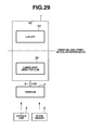
- Fig. 29 is a block diagram illustrating a portion of a peripheral device control system configured by an information processing apparatus and a peripheral device.
- Fig. 29 shows a case where the peripheral device control system as shown in Fig. 1 is not implemented on the network 4 but in a local port connection environment configured by a PC and a printer only.
- a utility 10 is installed in the PC 1.
- the utility 10 is the same as the utility 30 installed in the PC 2.
- the printing and print spooler interfaces are configured between the utility 10 and the LM 36.
- the data communication as described in each of the above embodiments can be performed between the utility 10 (printer manager) and the LM 36 via the printing and print spooler interfaces.
- the present invention is not limited to this.
- the present invention can be effectively utilized in acquiring arbitrary information concerning the printer.
- the present invention is implemented by utilizing the Bidi communications schema via the printing and print spooler interfaces.
- the present invention is not limited to this.
- the present invention can be implemented by utilizing a protocol having the same function as the above such as MIB and Universal Plug and Play (UPnP).
- UFP Universal Plug and Play
- a more universal system can be readily achieved by utilizing a standard specification.
- a color ink jet printer is used as an example of a printer.
- the present invention is not limited to this.
- an arbitrary printer such as a monochromatic LBP can be used.
- a personal computer is referred to as a client computer and a server computer.
- the present invention is not limited to this.
- the present invention can be effectively implemented by using an arbitrary terminal that can be used in the same usage as described above such as a DVD video player, a game machine, a set top box, and an Internet-ready home appliance.
- a printer is referred to as an example of a peripheral device.
- the present invention is not limited to this. That is, another peripheral device such as a copying machine, a facsimile, a scanner, a digital camera, and a device equipped with combined functions thereof can be applied to the present invention.
- Windows (registered trademark) XP is referred to as an OS.
- the present invention is not limited to this. That is, an arbitrary OS can be applied to the present invention.
- Ethernet registered trademark
- the network may have another arbitrary configuration.
- the USB interface is used as an interface between the PC 1 and the printer 3.
- the present invention is not limited to this. That is, an arbitrary interface such as Ethernet (registered trademark), wireless LAN, IEEE 1394 bus, Bluetooth, IrDA, parallel, and serial may be used.
- the timing at which the utility 30 (printer manager) acquires the schema route is based on the notification from a lower side (the LM 36 and the printer 3), as shown in step S2505 in Fig. 9 and step S3605 in Fig. 27.
- the timing at which the utility 30 obtains the schema route may be at a more applied timing.
- the timing may be taken in such a manner that an interruption of event is allowed to occur in the utility 30 and the utility 30 periodically issues an inquiry to the LM 36 or the printer 3 as to whether the acquiring route is present.
- the timing may be taken in such a manner that a button for acquiring the route is provided to the UI of the utility 30, and when there is a message indicating that the button is pressed, the presence of the route (method of acquiring) to be newly acquired is acquired from the utility 30 to the LM 36 or the printer 3.
- Fig. 30 is a flow chart of the processing performed by the utility 30 according to a fourth embodiment.
- step S3006 a detailed description is omitted because the same processing as steps shown in the flow chart of Fig. 10 described in the above embodiment is performed.
- the flow chart of Fig. 30 will now be described in detail.
- step S3001 when the printer manager is activated in step S3001, the main window as shown in Fig. 5 is displayed in step S3002. Then, the processing of interruption events every 5 seconds is started, and then a message loop is produced in step S3004.
- step S3005 it is determined whether an interruption event has occurred. If it is determined that the interruption event has occurred, the information shown in Fig. 14 is acquired and updated in step S3006.
- step S3007 it is determined whether the message loop produced in step S3004 receives a message. Then, in step S3008, it is determined whether the received message is the message "End”. If it is determined that the received message is the message "End” in step S3008, then, in step S3010, all the processing by the printer manager is terminated. On the other hand, if it is determined in step S3008 that the received message is a message other than the message "End", the processing corresponding to each message is performed (step S3009), and then the processing returns to step S3005. If the message is not received in step S3007, the processing returns to step S3005. If the interruption does not occur in step S3005, the processing advances to step S3007.
- the route that is the method of acquiring the schema is acquired, the route is written to a file and stored in a form in which the route can be reused when the PC is rebooted, and the printer manager uses the route thereafter.
- the convenience of the utility 30 can further be improved.
- the present invention can also be achieved by providing a system or a device with a storage medium which records program code of software implementing the functions of the embodiments and by reading and executing the program code stored in the storage medium with a computer of the system or the device (the CPU or the MPU).
- a computer of the system or the device the CPU or the MPU
- the program code of software that implements each function as shown in each flow chart of the embodiments is recorded on the storage medium.
- the program code itself which is read from the storage medium, implements the functions of the embodiments mentioned above, and accordingly, the program code and/or the storage medium storing said code constitutes the present invention.
- a flexible disk As the storage medium for supplying such program code, a flexible disk, a hard disk, an optical disk, a magneto-optical disk, a CD-ROM, a CD-R, a magnetic tape, a nonvolatile memory card, and a ROM can be used.
- the functions according to the embodiments described above can be implemented not only by executing the program code read by the computer, but also by processing in which an OS (operating system) or the like carries out a part of or the whole of the actual processing on the basis of the instruction given by the program code.
- an OS operating system
- a CPU and the like provided in the function expansion board or the function expansion unit can carry out a part of or the whole of the processing to implement the functions of the embodiments as described above.
Landscapes
- Engineering & Computer Science (AREA)
- Theoretical Computer Science (AREA)
- Physics & Mathematics (AREA)
- Human Computer Interaction (AREA)
- General Engineering & Computer Science (AREA)
- General Physics & Mathematics (AREA)
- Mathematical Physics (AREA)
- Accessory Devices And Overall Control Thereof (AREA)
- Computer And Data Communications (AREA)
- Two-Way Televisions, Distribution Of Moving Picture Or The Like (AREA)
Applications Claiming Priority (2)
| Application Number | Priority Date | Filing Date | Title |
|---|---|---|---|
| JP2005234620 | 2005-08-12 | ||
| JP2006194350A JP4795151B2 (ja) | 2005-08-12 | 2006-07-14 | 情報処理方法、情報処理装置、プログラム及び記憶媒体 |
Publications (2)
| Publication Number | Publication Date |
|---|---|
| EP1755031A2 true EP1755031A2 (de) | 2007-02-21 |
| EP1755031A3 EP1755031A3 (de) | 2010-06-09 |
Family
ID=37395952
Family Applications (1)
| Application Number | Title | Priority Date | Filing Date |
|---|---|---|---|
| EP06254105A Withdrawn EP1755031A3 (de) | 2005-08-12 | 2006-08-04 | Verfahren und Vorrichtung zur Informationsverarbeitung |
Country Status (5)
| Country | Link |
|---|---|
| US (1) | US8514427B2 (de) |
| EP (1) | EP1755031A3 (de) |
| JP (1) | JP4795151B2 (de) |
| CN (1) | CN1912823B (de) |
| RU (1) | RU2346320C2 (de) |
Families Citing this family (7)
| Publication number | Priority date | Publication date | Assignee | Title |
|---|---|---|---|---|
| JP4630783B2 (ja) * | 2004-12-16 | 2011-02-09 | キヤノン株式会社 | 周辺装置制御システム、印刷装置、周辺装置制御方法、及びプログラム |
| JP4795151B2 (ja) * | 2005-08-12 | 2011-10-19 | キヤノン株式会社 | 情報処理方法、情報処理装置、プログラム及び記憶媒体 |
| JP4669901B2 (ja) * | 2008-10-21 | 2011-04-13 | キヤノン株式会社 | 情報処理装置、情報処理方法及びプログラム |
| RU2480820C1 (ru) * | 2011-12-08 | 2013-04-27 | Учреждение Российской академии наук Научно-исследовательский институт системных исследований РАН (НИИСИ РАН) | Устройство обработки информации |
| JP5862475B2 (ja) * | 2012-06-18 | 2016-02-16 | 株式会社リコー | 出力管理装置、出力管理システム、プログラム |
| US10705865B2 (en) * | 2014-02-25 | 2020-07-07 | Red Hat, Inc. | Disk resize of a virtual machine |
| JP2024016353A (ja) * | 2022-07-26 | 2024-02-07 | キヤノン株式会社 | 情報処理装置、プログラム |
Family Cites Families (18)
| Publication number | Priority date | Publication date | Assignee | Title |
|---|---|---|---|---|
| US6055361A (en) * | 1995-06-22 | 2000-04-25 | Canon Kabushiki Kaisha | Printer control with monitor function |
| JP3501611B2 (ja) * | 1996-07-03 | 2004-03-02 | キヤノン株式会社 | 画像形成方法とその装置 |
| US6301012B1 (en) | 1998-04-24 | 2001-10-09 | Hewlett-Packard Company | Automatic configuration of a network printer |
| JP3697114B2 (ja) * | 1998-08-28 | 2005-09-21 | キヤノン株式会社 | 情報処理装置及び情報処理方法及び情報処理システム及び情報処理プログラムを記憶した記憶媒体及び情報処理プログラムを送出する送出装置及び情報処理プログラム製品 |
| JP4384023B2 (ja) * | 1998-08-28 | 2009-12-16 | キヤノン株式会社 | 情報処理装置及び情報処理方法及び情報処理システム及び情報処理プログラムを記憶した記憶媒体及び情報処理プログラムを送出する送出装置及び情報処理プログラム製品 |
| JP2001154816A (ja) * | 1999-12-01 | 2001-06-08 | Seiko Epson Corp | ステータス情報印刷プログラムを記録した媒体、印刷装置、印刷制御装置、ステータス情報印刷方法およびステータス情報印刷システム |
| US6814510B1 (en) | 2000-08-02 | 2004-11-09 | Xerox Corporation | Method and apparatus for automatic update of a printer driver configuration and status |
| DE60237383D1 (de) * | 2001-10-30 | 2010-09-30 | Sony Corp | Überwachungsverfahren für elektronische einrichtungen, elektronische einrichtung, computer und programm dafür |
| JP3854852B2 (ja) * | 2001-11-09 | 2006-12-06 | パナソニック コミュニケーションズ株式会社 | 管理情報送信装置、機器管理装置および機器管理システム |
| US7327482B2 (en) * | 2002-10-15 | 2008-02-05 | Sharp Laboratories Of America, Inc. | Integrated printer monitoring |
| JP2004213266A (ja) * | 2002-12-27 | 2004-07-29 | Kyocera Mita Corp | デバイス管理装置、およびこれを用いたデバイス管理システム |
| JP2005018558A (ja) * | 2003-06-27 | 2005-01-20 | Seiko Epson Corp | プリンタ用ユーティリティプログラム及び印刷システム |
| US7522299B2 (en) * | 2003-06-30 | 2009-04-21 | Microsoft Corporation | System and method for automatic configuration |
| US20050071483A1 (en) * | 2003-09-26 | 2005-03-31 | Tetsuro Motoyama | Method and system for supporting multiple protocols used to monitor networked devices in a remote monitoring system |
| KR20050075489A (ko) * | 2004-01-15 | 2005-07-21 | 유티스타콤코리아 유한회사 | 메타 mib 를 이용한 자동 업데이트 시스템 및 방법 |
| JP4387964B2 (ja) * | 2004-04-28 | 2009-12-24 | キヤノン株式会社 | 印刷システム、印刷ジョブ管理方法、プログラム及び記憶媒体 |
| US20060192985A1 (en) * | 2005-02-25 | 2006-08-31 | Konica Minolta Systems Laboratory, Inc. | Printing system |
| JP4795151B2 (ja) * | 2005-08-12 | 2011-10-19 | キヤノン株式会社 | 情報処理方法、情報処理装置、プログラム及び記憶媒体 |
-
2006
- 2006-07-14 JP JP2006194350A patent/JP4795151B2/ja not_active Expired - Fee Related
- 2006-07-26 US US11/460,096 patent/US8514427B2/en not_active Expired - Fee Related
- 2006-08-04 EP EP06254105A patent/EP1755031A3/de not_active Withdrawn
- 2006-08-11 CN CN200610109776.2A patent/CN1912823B/zh not_active Expired - Fee Related
- 2006-08-11 RU RU2006129227/09A patent/RU2346320C2/ru active
Also Published As
| Publication number | Publication date |
|---|---|
| RU2346320C2 (ru) | 2009-02-10 |
| CN1912823B (zh) | 2014-03-05 |
| US20070038667A1 (en) | 2007-02-15 |
| US8514427B2 (en) | 2013-08-20 |
| CN1912823A (zh) | 2007-02-14 |
| JP2007073037A (ja) | 2007-03-22 |
| JP4795151B2 (ja) | 2011-10-19 |
| RU2006129227A (ru) | 2008-02-20 |
| EP1755031A3 (de) | 2010-06-09 |
Similar Documents
| Publication | Publication Date | Title |
|---|---|---|
| US12056407B2 (en) | Information processing apparatus, method, system, and medium, with setup page that shows information indicating functions | |
| US8139500B2 (en) | Information processing device and method thereof, and computer program product | |
| US9377972B2 (en) | Host device, management server, and method of solving error of image forming appartus | |
| KR100838865B1 (ko) | 정보 처리 장치, 상태 표시 방법 및 기록 매체 | |
| JP4541579B2 (ja) | 印刷システム、ネットワークインターフェース装置、印刷装置、データ提供方法及び記憶媒体 | |
| US8384919B2 (en) | Information processing apparatus and peripheral apparatus control method | |
| JP2009059364A (ja) | データ処理システム、コンピュータ読取可能なデータ記憶媒体及び方法 | |
| US8438556B2 (en) | Peripheral device control system, its control method, and information processing apparatus, and computer program and computer-readable storage medium | |
| JP2007328450A (ja) | ポートモニタプログラム、データ処理方法、情報処理装置、及び記憶媒体 | |
| EP1857920A2 (de) | Druckverfahren und system | |
| EP1755031A2 (de) | Verfahren und Vorrichtung zur Informationsverarbeitung | |
| JP4668067B2 (ja) | 印刷装置、印刷方法、印刷装置のためのプログラム、印刷指示装置およびメモリ解放制御方法 | |
| US7246153B2 (en) | Information management apparatus, device control apparatus, information management method, and memory medium storing program | |
| US7633403B2 (en) | Information processing apparatus, information processing system, and information processing method | |
| JP4323876B2 (ja) | データ処理装置、その制御方法、及び制御プログラム | |
| KR100851117B1 (ko) | 정보 처리 방법 및 장치 | |
| US8045211B2 (en) | Image forming device | |
| JP2008097226A (ja) | 情報処理装置及び情報処理方法 | |
| JP5100798B2 (ja) | 情報処理装置、情報処理方法及びプログラム | |
| EP4576756A1 (de) | Druckvorrichtung, druckserver, informationsverarbeitungsvorrichtung und steuerungsverfahren dafür | |
| JP4865885B2 (ja) | 印刷システム、ネットワークインターフェース装置、ネットワークインターフェース装置の制御方法、及び記憶媒体 | |
| KR20250081913A (ko) | 인쇄 장치, 인쇄 장치의 제어 방법, 및 기록 매체 | |
| JP2007156994A (ja) | ホスト装置及び印刷制御方法 | |
| JP2008155483A (ja) | ネットワークプリンタ、ネットワークプリントシステムおよびプリンタドライバ | |
| JP2004220192A (ja) | 印刷システム |
Legal Events
| Date | Code | Title | Description |
|---|---|---|---|
| PUAI | Public reference made under article 153(3) epc to a published international application that has entered the european phase |
Free format text: ORIGINAL CODE: 0009012 |
|
| AK | Designated contracting states |
Kind code of ref document: A2 Designated state(s): AT BE BG CH CY CZ DE DK EE ES FI FR GB GR HU IE IS IT LI LT LU LV MC NL PL PT RO SE SI SK TR |
|
| AX | Request for extension of the european patent |
Extension state: AL BA HR MK YU |
|
| PUAL | Search report despatched |
Free format text: ORIGINAL CODE: 0009013 |
|
| AK | Designated contracting states |
Kind code of ref document: A3 Designated state(s): AT BE BG CH CY CZ DE DK EE ES FI FR GB GR HU IE IS IT LI LT LU LV MC NL PL PT RO SE SI SK TR |
|
| AX | Request for extension of the european patent |
Extension state: AL BA HR MK RS |
|
| 17P | Request for examination filed |
Effective date: 20101209 |
|
| AKX | Designation fees paid |
Designated state(s): DE ES FR GB IT NL |
|
| STAA | Information on the status of an ep patent application or granted ep patent |
Free format text: STATUS: THE APPLICATION HAS BEEN WITHDRAWN |
|
| 18W | Application withdrawn |
Effective date: 20160517 |