EP1753685B1 - Vorrichtung und verfahren zum verbinden von textilgarnen - Google Patents
Vorrichtung und verfahren zum verbinden von textilgarnen Download PDFInfo
- Publication number
- EP1753685B1 EP1753685B1 EP05752766A EP05752766A EP1753685B1 EP 1753685 B1 EP1753685 B1 EP 1753685B1 EP 05752766 A EP05752766 A EP 05752766A EP 05752766 A EP05752766 A EP 05752766A EP 1753685 B1 EP1753685 B1 EP 1753685B1
- Authority
- EP
- European Patent Office
- Prior art keywords
- yarn
- yarns
- control unit
- joining
- pincer
- Prior art date
- Legal status (The legal status is an assumption and is not a legal conclusion. Google has not performed a legal analysis and makes no representation as to the accuracy of the status listed.)
- Expired - Lifetime
Links
Images

Classifications
-
- B—PERFORMING OPERATIONS; TRANSPORTING
- B65—CONVEYING; PACKING; STORING; HANDLING THIN OR FILAMENTARY MATERIAL
- B65H—HANDLING THIN OR FILAMENTARY MATERIAL, e.g. SHEETS, WEBS, CABLES
- B65H69/00—Methods of, or devices for, interconnecting successive lengths of material; Knot-tying devices ;Control of the correct working of the interconnecting device
- B65H69/06—Methods of, or devices for, interconnecting successive lengths of material; Knot-tying devices ;Control of the correct working of the interconnecting device by splicing
- B65H69/061—Methods of, or devices for, interconnecting successive lengths of material; Knot-tying devices ;Control of the correct working of the interconnecting device by splicing using pneumatic means
- B65H69/063—Preparation of the yarn ends
- B65H69/065—Preparation of the yarn ends using mechanical means
-
- B—PERFORMING OPERATIONS; TRANSPORTING
- B65—CONVEYING; PACKING; STORING; HANDLING THIN OR FILAMENTARY MATERIAL
- B65H—HANDLING THIN OR FILAMENTARY MATERIAL, e.g. SHEETS, WEBS, CABLES
- B65H2701/00—Handled material; Storage means
- B65H2701/30—Handled filamentary material
- B65H2701/31—Textiles threads or artificial strands of filaments
Definitions
- the present invention concerns a device, and the relative method, for joining textile yarns, formed by a set of fibers twisted together.
- the various devices for clamping the ends, cutting the tails, stretching, the de-twisting and re-twisting of the parts of the yarn to be joined, and also the elements of the pneumatic joining chamber are individually driven by their own, distinct actuation means, able to be commanded independently and individually regulated, by an electronic unit, according to pre-set and pre-settable parameters and values.
- the electronic unit according to the characteristics of the yarn, the type of use of the yarn, the environmental conditions and the signals arriving from appropriate sensors, is suitable to send command signals to each of the actuation means so as to perform the sequence of various operations to join the yarns.
- a first type of joining device consists of pneumatic devices which uses the action of a fluid, normally air, on the fibers which make up the ends of the yarns to be joined. Normally, in the initial steps such devices act on two yarns so as to obtain, by means of scissors or pincer, two ends of a defined length and conformation, called tails. Subsequently, the two ends of the yarns to be joined are hit by a jet of compressed air so as to eliminate the residual twists, trying to make the fibers parallel and to reduce the quantity of the fibers affected by the join.
- a fluid normally air
- the techniques used to achieve this action are various, such as jets inclined with respect to the yarn, rotary jets, pulsating jets and other.
- the tails are inserted in a proper joining chamber, wherein a second jet of air penetrates the fibers giving mechanical resistance and, thanks to the geometric conformation of the chamber, closes the fibers together so as to give the join a good aesthetic appearance.
- a second jet of air penetrates the fibers giving mechanical resistance and, thanks to the geometric conformation of the chamber, closes the fibers together so as to give the join a good aesthetic appearance.
- Mainly mechanical devices are also known, which directly use the mechanical action on the fibers that make up the ends of the yarns to be joined.
- a first mechanical action called de-twisting
- de-twisting on the two ends of the yarns to be joined
- a central zone is obtained wherein the fibers are practically parallel and hence without mechanical resistance.
- the excess parts are torn off or cut, so as to obtain two tails of the desired length with parallel fibers.
- the tails are superimposed and then by means of a second mechanical action, or twist, opposite the first, the structure of the original yarn is reconstructed.
- Another type of devices are the mixed pneumatic-mechanical devices, such as for example as described in DE-A1-3131986 and in EP-A-0 227 370 , wherein first of all the mechanical action is used to de-twist the yarns and obtain segments of yarn with parallel fibers, then the fibers are penetrated by means of a jet of fluid, and finally a mechanical action is again performed in order to re-twist the fibers and regenerate the structure of the yarn.
- Such devices have not had a wide diffusion, despite the excellent results from both the point of view of aesthetics and of mechanical resistance, due to the great mechanical complexity in the industrial production.
- the purpose of the invention is therefore to achieve a device and a method for joining textile yarns which allow to obtain the desired technological results for a wide range of yarns, both in type and count, without increasing the complexity of the device and obviating the limits of known devices as mentioned above.
- a joining device for textile yarns according to the invention is of the mixed, pneumatic-mechanical type and comprises, as its main components, a pneumatic chamber, or joining chamber, means to grip the ends of the yarns, de-twisting means and re-twisting means cooperating with said gripping means, stretching means and cutting means.
- the components of the device indicated above are mechanically independent with respect to each other, at least from the functional and operational point of view, and can be activated independently, both in entity of movement and in step, by means of relative and distinct actuation means, on the commands of an electronic control unit, according to the program, the work parameters and the signals arriving from the sensors used.
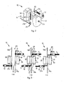
- the reference number 10 denotes generally a joining device for textile yarns, indicated by 16a and 16b in figs. 3a, 3b, 3c , according to a preferential embodiment of the present invention.
- the device 10 comprises a pneumatic joining chamber 13, able to be selectively opened and closed, inside which the ends of the yarns 16a, 16b to be joined are introduced.
- the pneumatic joining chamber 13 cooperates with respective gripping means 20 to grip the ends of the yarns 16a, 16b, suitable to perform at least some of the following functions:
- the gripping means 20 are located immediately outside the pneumatic chamber 13 and comprise a first and a second pincer arranged on opposite sides of the chamber 13, one (21a) above and the other (21b) below said joining chamber 13.
- Each of the pincers 21a, 21b acts on one of the two ends of the yarns 16a, 16b to be joined and particularly on the relative segments of free yarn.
- Each pincer 21a, 21b is mounted on a relative screw 11 made to rotate by an electric motor 12. Taking the screw 11 in correspondence with a first position of rear end-of-travel, indicated by A in fig. 3 , the pincers 21a, 21b open and are ready to receive the relative yarn 16a, 16b.
- the pincers 21a, 21b close, clamping inside them the relative yarn 16a, 16b.
- the pincers 21a, 21b perform a stretching action on the relative yarn 16a, 16b of a quantity proportional to the number of revolutions imparted to the relative motors 12.
- the entity of the stretching can be equal in the two yarns 16a, 16b, or also reciprocally different.
- the device 10 also comprises cutting means consisting of scissors 22 to cut the yarn, which can be sued, for particularly resistant yarns or yarns with an elastic core, so as to guarantee the interruption of the yarn.
- the scissors 22 are activated by feeding a pneumatic piston by means of a control electro-valve 23.
- the pneumatic joining chamber 13 is a device in which the function of penetration of the fibers is performed.
- the chamber 13 is formed by two separate movable shells, respectively 30 and 31 ( figs. 2, 3a) , at least one of which, in this case the shell 30, is equipped with a series of holes 32, advantageously with an axis perpendicular to the axis of the yarns 16a, 16b, from which pressurized fluid is made to exit, on the command of an electro-valve.
- the two shells 30, 31 are moved apart/closer from/to each other, advantageously by means of a pneumatic piston. They can thus assume a first, reciprocally distanced position (position D, fig. 3a ) wherein the joining chamber 13 is open and the yarns 16a, 16b can be introduced inside it, the ends of the yarns being retained by the respective pincers 21a, 21b.
- the two shells 30, 31 are taken into contact with each other (position E, fig. 3b ) and the joining chamber 13 is closed in sealed manner.
- the joining chamber 13 After having suitably prepared the two ends of the yarns 16a, 16b, the joining chamber 13 is closed and then, for a pre-set time, a command electro-valve is activated so that the fluid is introduced into the chamber 13 through the hole 32, and hits the fibers.
- the shape of the joining chamber 13 is advantageously such that the jet of fluid creates a vortex such that the fibers are bound together, creating a joining point between the two ends.
- the duration of the delivery of the jet of air to the yarns is defined by an electronic control unit 15 according to the characteristics of the yarn, the type of use of the yarn and the environmental conditions.
- the electronic control unit 15 is also suitable to drive the motors 12 of the pincers 21a, 21b according to the steps of the cycle and the entity of stretching to be imparted to the relative yarns 16a, 16b, the pneumatic piston that opens and closes the shells 30, 31 of the joining chamber 13, and, as we shall see hereafter, the members that drive the rotary pincers 14a, 14b of the scissors 22 and the members involved in the joining cycle.
- the joining chamber 13, in one and/or the other of the shells 30, 31, can be equipped with devices to clamp the yarns, which are particularly useful in the case of elasticized yarns.
- one or more pins 33 commanded pneumatically, can be selectively driven, on the command of the electronic control unit 15, to clamp the yarns 16a, 16b in the joining zone, preventing the elastic core of the yarn from retracting excessively and from escaping from the join.
- the device 10, according to a first variant, can be equipped with auxiliary components, selectively driven, to vary the delivery, pressure and temperature of the fluid injected.
- the auxiliary components are piloted by the control unit 15 according to the characteristics of the yarn, the type of use of the yarn and the environmental conditions.
- the device 10 is equipped with auxiliary components able to allow to inject into the joining chamber 13 a mixture of air and water, to a percentage modifiable by the control unit 15, according to the characteristics of the yarn, the type of use of the yarn and the environmental conditions.
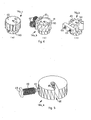
- the device 10 also comprises, as said above, a first 14a and a second 14b rotary pincers, suitable for the de-twisting and re-twisting of the respective yarns 16a, 16b.
- the rotary pincers 14a, 14b allow to impart to the relative yarns 16a, 16b a controllable number of rotations around their own axis. They are located immediately outside the pneumatic joining chamber 13, on opposite sides thereof, and each of them cooperates with a relative yarn-clamping pincer 21a, 21b. Each rotary pincer 14a, 14b acts on one of the two ends of the yarns 16a, 16b to be joined, and particularly on the segment of integral yarn.
- Figs. 4a, 4b, 4c show three embodiments of the rotary pincers 14a, 14b.
- the rotary pincer 14a, 14b is of the type with an eyelet 50 housing the relative yarn 16a, 16b and is made on a first gear 40 drawn by a second gear 140 solid with the shaft of an electric motor.
- the rotary pincer 14a, 14b has an eyelet 50 housing the relative yarn 16a, 16b and is mounted on a disk wherein magnets 41 are incorporated, whereas on the fixed outer part electric coils 42 are housed.
- the controlled rotation of the pincer is commanded, according to commands imparted by the electronic control unit 15.
- the pincer 14a, 14b again has the eyelet 50 housing the relative yarn and is mounted on a small pneumatic turbine 43.
- the clockwise/anti-clockwise rotation of the rotary pincer 14a, 14b occurs by activating suitable jets of air, for example 44 for clockwise rotation and 45 for anticlockwise rotation.
- each of the rotary pincers 14a, 14b is controlled by a sensor 46 ( fig. 5 ) which provides a suitable electric signal when a clamping pin 47, associated with a movement coil 48, has been taken to a position such as to allow the introduction of the yarns 16a, 16b.
- the pincer is opened by feeding the coil 48 which attracts the pin 47.
- the electric signal supplied by the sensor 46 allows the electronic control unit 15 to measure the number of revolutions performed by the pincer 14a, 14b.
- the electronic control unit 15 advantageously consists of an electronic card with a microprocessor in which the functions of processing, piloting the electric motors, commanding the electro-valves and reading the various sensors are integrated.
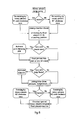
- the electronic control unit 15 performs a sequence of operations on the yarn. This sequence can be modified according to the signals arriving from some sensors so as to adapt to the new working conditions.
- control unit 15 can activate a function to control the join.
- This step can provide the activation of various control algorithms: a test every N cycles, random distribution, upon specific request of the operator.
- a force sensor can be provided, located on at least one of the pincers 21a, 21b that clamp one end of the join, in order to measure the tension of the yarn. If the function to test resistance and stretching is active, the control unit 15 reads the value supplied by the force sensor and processes it to determine the breaking load of the join.
- a movable pincer can be provided which clamps the other end of the join if the function to test resistance and stretching is active.
- the control unit 15, in this case, is therefore suitable to command the movement of the movable pincer so as to put the join in traction until it breaks.
- the control unit 15 then commands the movable pincer to move, so as to put the join in traction, and at the same time memorizes the values supplied by the load cell. At the moment the join breaks, the value read by the load cell is practically zeroed.
- the control unit 15 processes the data memorized and supplies the values of the breaking load and stretching of the join. Should these values not satisfy the required levels, the control unit 15 signals a malfunction of the device 10. The operator can set the device 10 so that this event causes it to stop, to avoid producing joins not in conformity with the required standards. Or, if the values obtained, while not optimum, are considered sufficient to continue functioning, the condition is only signaled, so that a maintenance and/or cleaning operation can be programmed.
Landscapes
- Engineering & Computer Science (AREA)
- Textile Engineering (AREA)
- Spinning Or Twisting Of Yarns (AREA)
- Yarns And Mechanical Finishing Of Yarns Or Ropes (AREA)
- Diaphragms For Electromechanical Transducers (AREA)
- Magnetically Actuated Valves (AREA)
- Superconductors And Manufacturing Methods Therefor (AREA)
- Treatment Of Fiber Materials (AREA)
Claims (20)
- Vorrichtung zum Verbinden von Textilgarnen (16a, 16b), aufweisend eine Verbindungskammer (13), in die die Enden von zwei zu verbindenden Garnen (16a, 16b) eingeführt werden können, wobei die Verbindungskammer (13) geschlossen werden kann und in ihrer Schließposition ein Verbindungsfach definiert, das geeignet ist, von einem Flüssigkeitsstrahl zum Erhalten der Verbindung getroffen zu werden, wobei die Vorrichtung für jedes der Garne (16a, 16b) aufweist: erste Klemm-Mittel (21a, 21b) zum Festklemmen der Enden des Garns (16a, 16b), zweite Greifmittel (14a, 14b), die sich im Wesentlichen um die Achse des jeweiligen Garns (16a, 16b) drehen zum Durchführen des Entdrehens und erneuten Verdrehens des Garns (16a, 16b), und Schneidemittel (22), dadurch gekennzeichnet, dass die Verbindungskammer (13), die Klemm-Mittel (21a, 21b) zum Festklemmen der Enden der Garne (16a, 16b) und die sich drehenden Greifmittel (14a, 14b), die entdrehen und verdrehen, geeignet sind, von jeweiligen und unabhängigen Antriebsmitteln angetrieben zu werden, die von den Befehlen einer elektronischen Steuereinheit (15) gesteuert werden, wobei die elektronische Steuereinheit (15) zum Regulieren mindestens des Startmoments, der Durchflussrate und/oder der Dauer der Abgabe des Flüssigkeitsstrahls auf die Garne gemäß mindestens einer aus den Eigenschaften des Garns, der Art der Verwendung des Garns und den Umweltbedingungen geeignet ist, wobei jedes der sich drehenden Greifmittel (14a, 14b) geeignet ist, dem Ende des jeweiligen Garns (16a, 16b) eine steuerbare Anzahl von Drehungen um dessen eigene Achse zum Entdrehen und erneuten Verdrehen desselben zu vermitteln, und wobei die Klemm-Mittel zwei Zangen aufweisen, eine (21a) über und die andere (21b) unter der Verbindungskammer (13), wobei jede der Zangen (21a, 21b) auf eines der beiden Enden der zu verbindenden Garne (16a, 16b) einwirkt und an einer jeweiligen Schraube (11) montiert ist, die von einem jeweiligen Motor (12) zum Drehen gebracht wird, wobei jeder der Motoren (12) zum Bewegen der jeweiligen Zange (21a, 21b) zum Durchführen eines Streckvorgangs an dem jeweiligen Garn (16a, 16b) in einer Größe geeignet ist, die proportional ist zu der dem jeweiligen Motor (12) vermittelten Anzahl von Umdrehungen, wobei die Größe der Streckung in den beiden Garnen (16a, 16b) gleich oder wechselseitig unterschiedlich sein kann.
- Vorrichtung gemäß Anspruch 1, dadurch gekennzeichnet, dass die elektronische Steuereinheit (15) zum Steuern des Antriebs der Motoren (12) geeignet ist für ein Bewegen der Zangenmittel (21a, 21b) aus einer ersten Position (A), in der die Zangenmittel (21a, 21b) sich öffnen und zum Aufnehmen des jeweiligen Garns (16a, 16b) bereit sind, einer zweiten Position (B), in der sich die Zangenmittel (21a, 21b) schließen, wobei sie das jeweilige Garn (16a, 16b) zwischen einander einklemmen, und einer dritten Position (C), in der die Funktion des Abreißens der Enden erreicht wird.
- Vorrichtung gemäß einem vorhergehenden Anspruch, dadurch gekennzeichnet, dass die Verbindungskammer (13) aus zwei bewegbaren Schalen (30, 31) gebildet ist, wobei mindestens eine davon mit Löchern (32) versehen ist, aus denen auf Befehl eines Elektroventils unter Druck stehende Flüssigkeit zum Austreten gebracht wird.
- Vorrichtung gemäß Anspruch 3, dadurch gekennzeichnet, dass die Schalen (30, 31) geeignet sind, voneinander weg/aufeinander zu bewegt zu werden, um eine erste Position im Abstand voneinander, in der die Verbindungskammer (13) offen ist und die Enden der Garne (16a, 16b), die von den jeweiligen Zangenmitteln (21a, 21b) gehalten werden, eingeführt werden können, und eine zweite Position in gegenseitigem Kontakt einzunehmen, in der die Verbindungskammer (13) dicht verschlossen ist zum Einführen des Fluids durch die Löcher (32) nach innen, so dass es die Fasern trifft und die Verbindung herbeigeführt wird.
- Vorrichtung gemäß Anspruch 3, dadurch gekennzeichnet, dass die Verbindungskammer (13) derart geformt ist, dass der Flüssigkeitsstrahl einen Strudel bildet, so dass die Fasern miteinander verbunden werden, eine Verbindungsstelle zwischen den beiden Enden bilden.
- Vorrichtung gemäß Anspruch 3, dadurch gekennzeichnet, dass die Verbindungskammer (13) in einer und/oder der anderen der Schalen (30, 31) Mittel (33) aufweist, die wahlweise aktiviert werden können zum Festklemmen der Garne (16a, 16b) in dem Verbindungsfach, insbesondere im Fall von elastischen Garnen.
- Vorrichtung gemäß einem vorhergehenden Anspruch, dadurch gekennzeichnet, dass die elektronische Steuereinheit (15) zum Regulieren der Drehrichtung und der Anzahl von Drehungen der Drehzangen (14a, 14b) geeignet ist, die das Entdrehen und das erneute Verdrehen der Garne (16a, 16b) gemäß den Eigenschaften des Garns, der Art der Verwendung des Garns und den Umweltbedingungen durchführen.
- Vorrichtung gemäß einem vorhergehenden Anspruch, dadurch gekennzeichnet, dass in dem Schritt des Entdrehens die Anzahl von Umdrehungen und die Richtung der Drehung mit den Eigenschaften des Garns verknüpft sind zum Erzielen der Aufhebung der Drehungen in der Nähe der End-Klemm-Zangen (21a, 21b).
- Vorrichtung gemäß Anspruch 7, dadurch gekennzeichnet, dass jede der Drehzahngen (14a, 14b) eine Öse (50) aufweist, die das jeweilige Garn (16a, 16b) aufnimmt, wobei die Winkelposition der Drehzangen (14a, 14b) durch einen Sensor (46) gesteuert wird, der ein passendes elektrisches Signal bereitstellt, wenn ein Klemmstift (47) in eine derartige Position gebracht wurde, dass das Einführen der Garne (16a, 16b) ermöglicht wird.
- Vorrichtung gemäß einem vorhergehenden Anspruch, dadurch gekennzeichnet, dass sie Mittel aufweist, die geeignet sind, von der elektronischen Steuereinheit (15) angetrieben zu werden, um die Durchflussrate, den Druck und die Temperatur der Flüssigkeit, die in die Verbindungskammer (13) injiziert wird, selektiv zu variieren.
- Vorrichtung gemäß einem vorhergehenden Anspruch, dadurch gekennzeichnet, dass sie Mittel aufweist, die geeignet sind, von der elektronischen Steuereinheit (15) angetrieben zu werden, um eine Mischung von Luft und Wasser in die Verbindungskammer (13) in einem regulierbaren Verhältnis gemäß den Eigenschaften des Garns, der Art der Verwendung des Garns und den Umweltbedingungen zu injizieren.
- Vorrichtung gemäß Anspruch 2, dadurch gekennzeichnet, dass die Steuereinheit die wahlweise Aktivierung der Zangenmittel (21a, 21b) bestimmen kann zum Einstellen des Startmoments, wenn das Strecken der beiden Garnsegmente (16a, 16b) erfolgt, gemäß den Eigenschaften des Garns, der Art der Verwendung des Garns und den Umweltbedingungen.
- Vorrichtung gemäß Anspruch 2, dadurch gekennzeichnet, dass die Steuereinheit (15) zum Bestimmen der selektiven Aktivierung der Zangenmittel (21a, 21b) geeignet ist zum Einstellen des Moments, wenn das Abreißen der beiden freien Enden von Garn gemäß den Eigenschaften des Garns, der Art der Verwendung des Garns und den Umweltbedingungen gesteuert wird.
- Vorrichtung gemäß einem vorhergehenden Anspruch, dadurch gekennzeichnet, dass die Steuereinheit (15) zum Bestimmen der selektiven Aktivierung von Schneidemitteln (22) in zeitlicher Korrelation zumindest mit den Zangenmitteln (21a, 21b), die die Enden der Garne ergreifen, und mit den Drehzangenmitteln (14a, 14b) gemäß den Eigenschaften des Garns, der Art der Verwendung des Garns und den Umweltbedingungen geeignet ist.
- Vorrichtung gemäß Anspruch 1, dadurch gekennzeichnet, dass die Drehzangenmittel (14a, 14b) von einem Elektromotor (12) antreibbar sind, der durch die Befehle der Steuereinheit (15) gesteuert wird.
- Vorrichtung gemäß Anspruch 1, dadurch gekennzeichnet, dass die Drehzangenmittel (14a, 14b) von pneumatischen Turbinenmitteln (43) antreibbar sind, die von den Befehlen der Steuereinheit (15) gesteuert werden.
- Vorrichtung gemäß Anspruch 1, dadurch gekennzeichnet, dass die Drehzangenmittel (14a, 14b) von elektrischen Spulenmitteln (42) antreibbar sind, die mit Magneten (41) zusammenwirken, und deren Antrieb durch die Befehle der Steuereinheit (15) gesteuert wird.
- Vorrichtung gemäß Anspruch 1, dadurch gekennzeichnet, dass an mindestens einem der Klemm-Mittel (21a, 21b), die die Enden der Garne (16a, 16b) greifen, Sensormittel vorhanden sind, die zum Durchführen eines Widerstands- und Streckungstestes an der eben gebildeten Verbindung geeignet sind.
- Vorrichtung gemäß Anspruch 18, dadurch gekennzeichnet, dass die Sensormittel mindestens einen Kraftmesser aufweisen.
- Verfahren zum Verbinden von Textilgarnen (16a, 16b) in einer Verbindungsvorrichtung (10) gemäß einem der vorhergehenden Ansprüche, dadurch gekennzeichnet, dass es in Folge mindestens die folgenden Schritte aufweist:- einen Schritt des Einführens der Garne (16a, 16b) in die Vorrichtung (10) und des Festklemmens ihrer Enden durch die jeweiligen Zangenmittel (21a, 21b) und die jeweiligen Drehzangenmittel (14a, 14b),- einen Schritt des Entdrehens der Garne, wobei die elektronische Steuereinheit (15) die Drehzangenmittel (14a, 14b) steuert, mit einer Anzahl von Umdrehungen und einer Drehrichtung zu drehen, die mit den Eigenschaften des Garns korreliert,- einen Schritt des Schließens der Verbindungskammer (13),- einen Schritt, bei dem die Steuereinheit (15) die Zangenmittel (21a, 21b) steuert, sich mittels eines gesteuerten Antriebs der jeweiligen Motoren (12) zu bewegen, um die Garne (16a, 16b), die von den Drehzangen (14a, 14b) eingeklemmt sind, zu strecken, wobei die Größe der linearen Bewegung der Zangenmittel (21a, 21b) an die Eigenschaften des Garns gekoppelt ist zum entsprechenden Einstellen der Größe der vermittelten Streckung,- einen Schritt, bei dem die Steuereinheit (15) die Zangenmitteln (21a, 21b) steuert, sich bis zum Vervollständigen des Arbeitsweges zu bewegen, so dass die beiden Enden zu entfernenden Enden des Garns (16a, 16b) mittels Ansaugens zum Reißen gebracht werden,- einen Schritt, bei dem die Steuereinheit (15) das Schneidemittel (22) aktiviert zum Sicherstellen des Lösens der beiden zu entfernenden Garnsegmente,- einen Schritt, bei dem die Steuereinheit (15) den Fluidstrahl in der Verbindungskammer (13) steuert, wobei Startmoment, Durchflussrate und Dauer des Strahls eine Funktion der Eigenschaften des Garns und der eingestellten Parameter sind,- einen Schritt des erneuten Verdrehens der Garne (16a, 16b), wobei die Steuereinheit (15) die Drehzangen (14a, 14b) zum Drehen in der entgegengesetzten Richtung relativ zu der während des Entdrehens angenommenen Richtung steuert, wobei die Anzahl von Umdrehungen der Drehzangen (14a, 14b) eine Funktion der Eigenschaften des Garns und der eingestellten Parameter ist,- einen Arbeitsgang-Fertigstellungsschritt, bei dem die Steuereinheit (15) die Schalen (30, 31) der Verbindungskammer (13) zum Öffnen steuert, dann die Drehzangen (14a, 14b) gelöst werden und schließlich die End-Klemm-Zangen (21a, 21b) in ihre Position zurückkehren.
Applications Claiming Priority (2)
| Application Number | Priority Date | Filing Date | Title |
|---|---|---|---|
| IT000113A ITUD20040113A1 (it) | 2004-05-28 | 2004-05-28 | Dispositivo e procedimento per la giunzione |
| PCT/EP2005/052415 WO2005118449A1 (en) | 2004-05-28 | 2005-05-27 | Device and method for joining textile yarns |
Publications (2)
| Publication Number | Publication Date |
|---|---|
| EP1753685A1 EP1753685A1 (de) | 2007-02-21 |
| EP1753685B1 true EP1753685B1 (de) | 2009-09-30 |
Family
ID=34956261
Family Applications (1)
| Application Number | Title | Priority Date | Filing Date |
|---|---|---|---|
| EP05752766A Expired - Lifetime EP1753685B1 (de) | 2004-05-28 | 2005-05-27 | Vorrichtung und verfahren zum verbinden von textilgarnen |
Country Status (6)
| Country | Link |
|---|---|
| EP (1) | EP1753685B1 (de) |
| CN (1) | CN1960928B (de) |
| AT (1) | ATE444256T1 (de) |
| DE (1) | DE602005016919D1 (de) |
| IT (1) | ITUD20040113A1 (de) |
| WO (1) | WO2005118449A1 (de) |
Families Citing this family (5)
| Publication number | Priority date | Publication date | Assignee | Title |
|---|---|---|---|---|
| DE102006000824A1 (de) | 2006-01-05 | 2007-07-12 | Saurer Gmbh & Co. Kg | Fadenspleißvorrichtung für eine Kreuzspulen herstellende Textilmaschine |
| ITUD20070096A1 (it) * | 2007-05-30 | 2008-11-30 | Atex Spa | Dispositivo di giunzione e procedimento di giunzione |
| DE102012103346A1 (de) | 2012-04-17 | 2013-10-17 | Maschinenfabrik Rieter Ag | Fadenspleißvorrichtung mit einer Einrichtung zur Festigkeitsprüfung von Fadenverbindungen |
| WO2016149845A1 (de) * | 2015-03-20 | 2016-09-29 | Uster Technologies Ag | Halbautomatische garnwechselvorrichtung für ein garnprüfgerät |
| IT201900021258A1 (it) * | 2019-11-15 | 2021-05-15 | Hayabusa S R L | Dispositivo di giunzione di fili tessili e relativo metodo di giunzione |
Family Cites Families (9)
| Publication number | Priority date | Publication date | Assignee | Title |
|---|---|---|---|---|
| CS564881A2 (en) * | 1980-08-02 | 1991-02-12 | Schlafhorst & Co W | Method of textile threads connecting and entwining device for realization of this method |
| DE3131986A1 (de) * | 1980-08-02 | 1983-03-03 | W. Schlafhorst & Co, 4050 Mönchengladbach | Druckgasspleissvorrichtung fuer textilfaeden |
| DE3114539A1 (de) * | 1981-04-10 | 1983-02-24 | W. Schlafhorst & Co, 4050 Mönchengladbach | Vorrichtung zum herstellen einer knotenlosen fadenverbindung |
| IT1194072B (it) * | 1981-06-16 | 1988-09-14 | Mesdan Spa | Apparecchio per la giunzione di filati tessili con l'ausilio di aria compressa |
| DE3151270A1 (de) * | 1981-12-24 | 1983-07-07 | W. Schlafhorst & Co, 4050 Mönchengladbach | Verfahren und vorrichtung zum knotenfreien verbinden zweier faeden |
| EP0227370A3 (de) * | 1985-12-09 | 1987-09-16 | Pentwyn Precision Ltd. | Pneumatische Spleissvorrichtung mit Faden-Verdrillungseinrichtung |
| DE4008640A1 (de) * | 1990-03-17 | 1991-09-19 | Stahlecker Gmbh Wilhelm | Spleissvorrichtung zum verbinden von faeden |
| IT1316370B1 (it) * | 2000-02-15 | 2003-04-10 | Mesdan Spa | Dispositivo e procedimento per la giunzione di fili tessili mediantearia compressa e liquido |
| DE10124832A1 (de) * | 2001-05-22 | 2002-11-28 | Schlafhorst & Co W | Fadenspleissvorrichtung |
-
2004
- 2004-05-28 IT IT000113A patent/ITUD20040113A1/it unknown
-
2005
- 2005-05-27 AT AT05752766T patent/ATE444256T1/de not_active IP Right Cessation
- 2005-05-27 CN CN2005800174040A patent/CN1960928B/zh not_active Expired - Fee Related
- 2005-05-27 DE DE602005016919T patent/DE602005016919D1/de not_active Expired - Lifetime
- 2005-05-27 EP EP05752766A patent/EP1753685B1/de not_active Expired - Lifetime
- 2005-05-27 WO PCT/EP2005/052415 patent/WO2005118449A1/en not_active Ceased
Also Published As
| Publication number | Publication date |
|---|---|
| ITUD20040113A1 (it) | 2004-08-28 |
| WO2005118449A1 (en) | 2005-12-15 |
| ATE444256T1 (de) | 2009-10-15 |
| CN1960928A (zh) | 2007-05-09 |
| CN1960928B (zh) | 2011-07-27 |
| EP1753685A1 (de) | 2007-02-21 |
| DE602005016919D1 (de) | 2009-11-12 |
Similar Documents
| Publication | Publication Date | Title |
|---|---|---|
| US5680751A (en) | Pneumatic thread or yarn joining apparatus for installation on textile machines, in particular on automatic bobbin winding machines | |
| EP1753685B1 (de) | Vorrichtung und verfahren zum verbinden von textilgarnen | |
| US6167919B1 (en) | Method and device for the twisting of at least two single-lines | |
| US5269244A (en) | Thread processing machine having a thread changing device | |
| JP5508698B2 (ja) | ミシン及びこのタイプのミシンを用いてシームの初めを縫う方法 | |
| EP2141105A1 (de) | Spleisskopf, spleissvorrichtung und spleissverfahren | |
| JP2015036116A (ja) | ボタン縫い糸の根巻き装置 | |
| CN114555500B (zh) | 用于连结纺织纱线的连结装置和制成单根纱线的方法 | |
| EP0600297A2 (de) | Mehrfarben-Stickmaschine | |
| KR930009398B1 (ko) | 의복단추생크부의 감침방법 및 장치 | |
| WO2005002377A1 (en) | Button wrapping and knotting method and apparatus thereof | |
| US5477893A (en) | Knot-tying mechanism | |
| US20010003894A1 (en) | Device for the pneumatic splicing of threads or yarns and a process to carry out such splicing | |
| JPH06510823A (ja) | グリッパ及び投射織機用よこ糸供給装置 | |
| US20210037720A1 (en) | Apparatus for placing wire fasteners | |
| JP2001519484A (ja) | より縁を形成する装置の電動機のための制御部 | |
| US4607482A (en) | Fluid yarn splicing device | |
| EP4573912A1 (de) | Verschliessmaschine zum verschliessen von wurstwaren | |
| US3868133A (en) | Pneumatic yarn knotter mechanism | |
| CN204959264U (zh) | 可调整线段拉伸量的拉链车缝机 | |
| CN220132501U (zh) | 一种旋转机头用电热毯发热丝缝纫装置 | |
| CN117758404A (zh) | 纺织纱线两个相对末端部分的无结气动捻接的设备和方法 | |
| JP3338366B2 (ja) | 多色緯入れ織機の緯糸制御方法 | |
| JP2008220820A (ja) | 電動式ミシン | |
| JPH071787Y2 (ja) | 巻線機のノズル装置 |
Legal Events
| Date | Code | Title | Description |
|---|---|---|---|
| PUAI | Public reference made under article 153(3) epc to a published international application that has entered the european phase |
Free format text: ORIGINAL CODE: 0009012 |
|
| 17P | Request for examination filed |
Effective date: 20061218 |
|
| AK | Designated contracting states |
Kind code of ref document: A1 Designated state(s): AT BE BG CH CY CZ DE DK EE ES FI FR GB GR HU IE IS IT LI LT LU MC NL PL PT RO SE SI SK TR |
|
| DAX | Request for extension of the european patent (deleted) | ||
| 17Q | First examination report despatched |
Effective date: 20080320 |
|
| GRAP | Despatch of communication of intention to grant a patent |
Free format text: ORIGINAL CODE: EPIDOSNIGR1 |
|
| GRAS | Grant fee paid |
Free format text: ORIGINAL CODE: EPIDOSNIGR3 |
|
| GRAA | (expected) grant |
Free format text: ORIGINAL CODE: 0009210 |
|
| RAP1 | Party data changed (applicant data changed or rights of an application transferred) |
Owner name: ATEX INDUSTRIES S.R.L. |
|
| RIN1 | Information on inventor provided before grant (corrected) |
Inventor name: FABRIS GIANLUCA |
|
| AK | Designated contracting states |
Kind code of ref document: B1 Designated state(s): AT BE BG CH CY CZ DE DK EE ES FI FR GB GR HU IE IS IT LI LT LU MC NL PL PT RO SE SI SK TR |
|
| REG | Reference to a national code |
Ref country code: GB Ref legal event code: FG4D Ref country code: CH Ref legal event code: EP |
|
| REG | Reference to a national code |
Ref country code: IE Ref legal event code: FG4D |
|
| REF | Corresponds to: |
Ref document number: 602005016919 Country of ref document: DE Date of ref document: 20091112 Kind code of ref document: P |
|
| PG25 | Lapsed in a contracting state [announced via postgrant information from national office to epo] |
Ref country code: LT Free format text: LAPSE BECAUSE OF FAILURE TO SUBMIT A TRANSLATION OF THE DESCRIPTION OR TO PAY THE FEE WITHIN THE PRESCRIBED TIME-LIMIT Effective date: 20090930 Ref country code: SE Free format text: LAPSE BECAUSE OF FAILURE TO SUBMIT A TRANSLATION OF THE DESCRIPTION OR TO PAY THE FEE WITHIN THE PRESCRIBED TIME-LIMIT Effective date: 20090930 Ref country code: FI Free format text: LAPSE BECAUSE OF FAILURE TO SUBMIT A TRANSLATION OF THE DESCRIPTION OR TO PAY THE FEE WITHIN THE PRESCRIBED TIME-LIMIT Effective date: 20090930 |
|
| LTIE | Lt: invalidation of european patent or patent extension |
Effective date: 20090930 |
|
| PG25 | Lapsed in a contracting state [announced via postgrant information from national office to epo] |
Ref country code: SI Free format text: LAPSE BECAUSE OF FAILURE TO SUBMIT A TRANSLATION OF THE DESCRIPTION OR TO PAY THE FEE WITHIN THE PRESCRIBED TIME-LIMIT Effective date: 20090930 Ref country code: PL Free format text: LAPSE BECAUSE OF FAILURE TO SUBMIT A TRANSLATION OF THE DESCRIPTION OR TO PAY THE FEE WITHIN THE PRESCRIBED TIME-LIMIT Effective date: 20090930 |
|
| NLV1 | Nl: lapsed or annulled due to failure to fulfill the requirements of art. 29p and 29m of the patents act | ||
| PG25 | Lapsed in a contracting state [announced via postgrant information from national office to epo] |
Ref country code: RO Free format text: LAPSE BECAUSE OF FAILURE TO SUBMIT A TRANSLATION OF THE DESCRIPTION OR TO PAY THE FEE WITHIN THE PRESCRIBED TIME-LIMIT Effective date: 20090930 Ref country code: CZ Free format text: LAPSE BECAUSE OF FAILURE TO SUBMIT A TRANSLATION OF THE DESCRIPTION OR TO PAY THE FEE WITHIN THE PRESCRIBED TIME-LIMIT Effective date: 20090930 Ref country code: EE Free format text: LAPSE BECAUSE OF FAILURE TO SUBMIT A TRANSLATION OF THE DESCRIPTION OR TO PAY THE FEE WITHIN THE PRESCRIBED TIME-LIMIT Effective date: 20090930 Ref country code: IS Free format text: LAPSE BECAUSE OF FAILURE TO SUBMIT A TRANSLATION OF THE DESCRIPTION OR TO PAY THE FEE WITHIN THE PRESCRIBED TIME-LIMIT Effective date: 20100130 Ref country code: ES Free format text: LAPSE BECAUSE OF FAILURE TO SUBMIT A TRANSLATION OF THE DESCRIPTION OR TO PAY THE FEE WITHIN THE PRESCRIBED TIME-LIMIT Effective date: 20100110 Ref country code: PT Free format text: LAPSE BECAUSE OF FAILURE TO SUBMIT A TRANSLATION OF THE DESCRIPTION OR TO PAY THE FEE WITHIN THE PRESCRIBED TIME-LIMIT Effective date: 20100201 |
|
| PG25 | Lapsed in a contracting state [announced via postgrant information from national office to epo] |
Ref country code: SK Free format text: LAPSE BECAUSE OF FAILURE TO SUBMIT A TRANSLATION OF THE DESCRIPTION OR TO PAY THE FEE WITHIN THE PRESCRIBED TIME-LIMIT Effective date: 20090930 Ref country code: CY Free format text: LAPSE BECAUSE OF FAILURE TO SUBMIT A TRANSLATION OF THE DESCRIPTION OR TO PAY THE FEE WITHIN THE PRESCRIBED TIME-LIMIT Effective date: 20090930 |
|
| PG25 | Lapsed in a contracting state [announced via postgrant information from national office to epo] |
Ref country code: BE Free format text: LAPSE BECAUSE OF FAILURE TO SUBMIT A TRANSLATION OF THE DESCRIPTION OR TO PAY THE FEE WITHIN THE PRESCRIBED TIME-LIMIT Effective date: 20090930 Ref country code: AT Free format text: LAPSE BECAUSE OF FAILURE TO SUBMIT A TRANSLATION OF THE DESCRIPTION OR TO PAY THE FEE WITHIN THE PRESCRIBED TIME-LIMIT Effective date: 20090930 |
|
| PG25 | Lapsed in a contracting state [announced via postgrant information from national office to epo] |
Ref country code: NL Free format text: LAPSE BECAUSE OF FAILURE TO SUBMIT A TRANSLATION OF THE DESCRIPTION OR TO PAY THE FEE WITHIN THE PRESCRIBED TIME-LIMIT Effective date: 20090930 Ref country code: DK Free format text: LAPSE BECAUSE OF FAILURE TO SUBMIT A TRANSLATION OF THE DESCRIPTION OR TO PAY THE FEE WITHIN THE PRESCRIBED TIME-LIMIT Effective date: 20090930 |
|
| PLBE | No opposition filed within time limit |
Free format text: ORIGINAL CODE: 0009261 |
|
| STAA | Information on the status of an ep patent application or granted ep patent |
Free format text: STATUS: NO OPPOSITION FILED WITHIN TIME LIMIT |
|
| 26N | No opposition filed |
Effective date: 20100701 |
|
| PG25 | Lapsed in a contracting state [announced via postgrant information from national office to epo] |
Ref country code: GR Free format text: LAPSE BECAUSE OF FAILURE TO SUBMIT A TRANSLATION OF THE DESCRIPTION OR TO PAY THE FEE WITHIN THE PRESCRIBED TIME-LIMIT Effective date: 20091231 |
|
| PG25 | Lapsed in a contracting state [announced via postgrant information from national office to epo] |
Ref country code: MC Free format text: LAPSE BECAUSE OF NON-PAYMENT OF DUE FEES Effective date: 20100531 |
|
| REG | Reference to a national code |
Ref country code: CH Ref legal event code: PL |
|
| GBPC | Gb: european patent ceased through non-payment of renewal fee |
Effective date: 20100527 |
|
| REG | Reference to a national code |
Ref country code: FR Ref legal event code: ST Effective date: 20110131 |
|
| PG25 | Lapsed in a contracting state [announced via postgrant information from national office to epo] |
Ref country code: LI Free format text: LAPSE BECAUSE OF NON-PAYMENT OF DUE FEES Effective date: 20100531 Ref country code: CH Free format text: LAPSE BECAUSE OF NON-PAYMENT OF DUE FEES Effective date: 20100531 |
|
| PG25 | Lapsed in a contracting state [announced via postgrant information from national office to epo] |
Ref country code: IE Free format text: LAPSE BECAUSE OF NON-PAYMENT OF DUE FEES Effective date: 20100527 |
|
| PG25 | Lapsed in a contracting state [announced via postgrant information from national office to epo] |
Ref country code: FR Free format text: LAPSE BECAUSE OF NON-PAYMENT OF DUE FEES Effective date: 20100531 |
|
| PG25 | Lapsed in a contracting state [announced via postgrant information from national office to epo] |
Ref country code: GB Free format text: LAPSE BECAUSE OF NON-PAYMENT OF DUE FEES Effective date: 20100527 |
|
| PGFP | Annual fee paid to national office [announced via postgrant information from national office to epo] |
Ref country code: DE Payment date: 20120523 Year of fee payment: 8 |
|
| PG25 | Lapsed in a contracting state [announced via postgrant information from national office to epo] |
Ref country code: LU Free format text: LAPSE BECAUSE OF NON-PAYMENT OF DUE FEES Effective date: 20100527 Ref country code: HU Free format text: LAPSE BECAUSE OF FAILURE TO SUBMIT A TRANSLATION OF THE DESCRIPTION OR TO PAY THE FEE WITHIN THE PRESCRIBED TIME-LIMIT Effective date: 20100401 Ref country code: BG Free format text: LAPSE BECAUSE OF FAILURE TO SUBMIT A TRANSLATION OF THE DESCRIPTION OR TO PAY THE FEE WITHIN THE PRESCRIBED TIME-LIMIT Effective date: 20090930 |
|
| PGFP | Annual fee paid to national office [announced via postgrant information from national office to epo] |
Ref country code: IT Payment date: 20120523 Year of fee payment: 8 |
|
| PG25 | Lapsed in a contracting state [announced via postgrant information from national office to epo] |
Ref country code: TR Free format text: LAPSE BECAUSE OF FAILURE TO SUBMIT A TRANSLATION OF THE DESCRIPTION OR TO PAY THE FEE WITHIN THE PRESCRIBED TIME-LIMIT Effective date: 20090930 |
|
| PG25 | Lapsed in a contracting state [announced via postgrant information from national office to epo] |
Ref country code: DE Free format text: LAPSE BECAUSE OF NON-PAYMENT OF DUE FEES Effective date: 20131203 |
|
| REG | Reference to a national code |
Ref country code: DE Ref legal event code: R119 Ref document number: 602005016919 Country of ref document: DE Effective date: 20131203 |
|
| PG25 | Lapsed in a contracting state [announced via postgrant information from national office to epo] |
Ref country code: IT Free format text: LAPSE BECAUSE OF NON-PAYMENT OF DUE FEES Effective date: 20130527 |