EP1752699A2 - Leitungsverbund zwischen einem Fitting und einem Verbundrohr sowie ein Verfahren zur Herstellung des Leitungsverbundes - Google Patents
Leitungsverbund zwischen einem Fitting und einem Verbundrohr sowie ein Verfahren zur Herstellung des Leitungsverbundes Download PDFInfo
- Publication number
- EP1752699A2 EP1752699A2 EP06016782A EP06016782A EP1752699A2 EP 1752699 A2 EP1752699 A2 EP 1752699A2 EP 06016782 A EP06016782 A EP 06016782A EP 06016782 A EP06016782 A EP 06016782A EP 1752699 A2 EP1752699 A2 EP 1752699A2
- Authority
- EP
- European Patent Office
- Prior art keywords
- fitting
- layer
- composite
- pipe
- composite pipe
- Prior art date
- Legal status (The legal status is an assumption and is not a legal conclusion. Google has not performed a legal analysis and makes no representation as to the accuracy of the status listed.)
- Withdrawn
Links
- 238000004519 manufacturing process Methods 0.000 title claims abstract description 8
- 239000002131 composite material Substances 0.000 title claims description 98
- 238000000034 method Methods 0.000 title claims description 4
- 238000010168 coupling process Methods 0.000 title 2
- 238000005859 coupling reaction Methods 0.000 title 2
- 239000004033 plastic Substances 0.000 claims abstract description 37
- 229920003023 plastic Polymers 0.000 claims abstract description 37
- 229910052751 metal Inorganic materials 0.000 claims abstract description 27
- 239000002184 metal Substances 0.000 claims abstract description 27
- -1 polyethylene Polymers 0.000 claims abstract description 16
- 239000011324 bead Substances 0.000 claims abstract description 14
- 238000010438 heat treatment Methods 0.000 claims abstract description 14
- 239000004743 Polypropylene Substances 0.000 claims abstract description 12
- 229920001155 polypropylene Polymers 0.000 claims abstract description 12
- 239000004698 Polyethylene Substances 0.000 claims abstract description 5
- 229920000573 polyethylene Polymers 0.000 claims abstract description 5
- 229910052782 aluminium Inorganic materials 0.000 claims abstract description 4
- XAGFODPZIPBFFR-UHFFFAOYSA-N aluminium Chemical compound [Al] XAGFODPZIPBFFR-UHFFFAOYSA-N 0.000 claims abstract description 4
- 229910001220 stainless steel Inorganic materials 0.000 claims abstract description 4
- 239000010935 stainless steel Substances 0.000 claims abstract description 4
- 239000010410 layer Substances 0.000 claims description 87
- 239000000463 material Substances 0.000 claims description 11
- 239000012790 adhesive layer Substances 0.000 claims description 8
- 238000009434 installation Methods 0.000 claims description 7
- 229920001083 polybutene Polymers 0.000 claims description 4
- 238000005520 cutting process Methods 0.000 claims description 2
- 238000002844 melting Methods 0.000 claims description 2
- 230000008018 melting Effects 0.000 claims description 2
- 238000005304 joining Methods 0.000 abstract description 9
- 230000004927 fusion Effects 0.000 abstract description 2
- 239000004411 aluminium Substances 0.000 abstract 1
- 238000003780 insertion Methods 0.000 description 8
- 230000037431 insertion Effects 0.000 description 8
- 229920000642 polymer Polymers 0.000 description 5
- 238000006073 displacement reaction Methods 0.000 description 2
- 239000012530 fluid Substances 0.000 description 2
- 239000004831 Hot glue Substances 0.000 description 1
- 238000004026 adhesive bonding Methods 0.000 description 1
- 238000005452 bending Methods 0.000 description 1
- 238000001816 cooling Methods 0.000 description 1
- 238000009826 distribution Methods 0.000 description 1
- 239000000155 melt Substances 0.000 description 1
- 230000003647 oxidation Effects 0.000 description 1
- 238000007254 oxidation reaction Methods 0.000 description 1
- 230000001105 regulatory effect Effects 0.000 description 1
- 230000002787 reinforcement Effects 0.000 description 1
- 239000012815 thermoplastic material Substances 0.000 description 1
- XLYOFNOQVPJJNP-UHFFFAOYSA-N water Substances O XLYOFNOQVPJJNP-UHFFFAOYSA-N 0.000 description 1
- 238000003466 welding Methods 0.000 description 1
Images

Classifications
-
- B—PERFORMING OPERATIONS; TRANSPORTING
- B29—WORKING OF PLASTICS; WORKING OF SUBSTANCES IN A PLASTIC STATE IN GENERAL
- B29C—SHAPING OR JOINING OF PLASTICS; SHAPING OF MATERIAL IN A PLASTIC STATE, NOT OTHERWISE PROVIDED FOR; AFTER-TREATMENT OF THE SHAPED PRODUCTS, e.g. REPAIRING
- B29C65/00—Joining or sealing of preformed parts, e.g. welding of plastics materials; Apparatus therefor
- B29C65/02—Joining or sealing of preformed parts, e.g. welding of plastics materials; Apparatus therefor by heating, with or without pressure
- B29C65/14—Joining or sealing of preformed parts, e.g. welding of plastics materials; Apparatus therefor by heating, with or without pressure using wave energy, i.e. electromagnetic radiation, or particle radiation
- B29C65/1429—Joining or sealing of preformed parts, e.g. welding of plastics materials; Apparatus therefor by heating, with or without pressure using wave energy, i.e. electromagnetic radiation, or particle radiation characterised by the way of heating the interface
- B29C65/1432—Joining or sealing of preformed parts, e.g. welding of plastics materials; Apparatus therefor by heating, with or without pressure using wave energy, i.e. electromagnetic radiation, or particle radiation characterised by the way of heating the interface direct heating of the surfaces to be joined
-
- B—PERFORMING OPERATIONS; TRANSPORTING
- B29—WORKING OF PLASTICS; WORKING OF SUBSTANCES IN A PLASTIC STATE IN GENERAL
- B29B—PREPARATION OR PRETREATMENT OF THE MATERIAL TO BE SHAPED; MAKING GRANULES OR PREFORMS; RECOVERY OF PLASTICS OR OTHER CONSTITUENTS OF WASTE MATERIAL CONTAINING PLASTICS
- B29B13/00—Conditioning or physical treatment of the material to be shaped
- B29B13/02—Conditioning or physical treatment of the material to be shaped by heating
- B29B13/023—Half-products, e.g. films, plates
- B29B13/024—Hollow bodies, e.g. tubes or profiles
- B29B13/025—Tube ends
-
- B—PERFORMING OPERATIONS; TRANSPORTING
- B29—WORKING OF PLASTICS; WORKING OF SUBSTANCES IN A PLASTIC STATE IN GENERAL
- B29C—SHAPING OR JOINING OF PLASTICS; SHAPING OF MATERIAL IN A PLASTIC STATE, NOT OTHERWISE PROVIDED FOR; AFTER-TREATMENT OF THE SHAPED PRODUCTS, e.g. REPAIRING
- B29C65/00—Joining or sealing of preformed parts, e.g. welding of plastics materials; Apparatus therefor
- B29C65/02—Joining or sealing of preformed parts, e.g. welding of plastics materials; Apparatus therefor by heating, with or without pressure
- B29C65/10—Joining or sealing of preformed parts, e.g. welding of plastics materials; Apparatus therefor by heating, with or without pressure using hot gases (e.g. combustion gases) or flames coming in contact with at least one of the parts to be joined
-
- B—PERFORMING OPERATIONS; TRANSPORTING
- B29—WORKING OF PLASTICS; WORKING OF SUBSTANCES IN A PLASTIC STATE IN GENERAL
- B29C—SHAPING OR JOINING OF PLASTICS; SHAPING OF MATERIAL IN A PLASTIC STATE, NOT OTHERWISE PROVIDED FOR; AFTER-TREATMENT OF THE SHAPED PRODUCTS, e.g. REPAIRING
- B29C66/00—General aspects of processes or apparatus for joining preformed parts
- B29C66/01—General aspects dealing with the joint area or with the area to be joined
- B29C66/02—Preparation of the material, in the area to be joined, prior to joining or welding
- B29C66/022—Mechanical pre-treatments, e.g. reshaping
- B29C66/0224—Mechanical pre-treatments, e.g. reshaping with removal of material
- B29C66/02245—Abrading, e.g. grinding, sanding, sandblasting or scraping
-
- B—PERFORMING OPERATIONS; TRANSPORTING
- B29—WORKING OF PLASTICS; WORKING OF SUBSTANCES IN A PLASTIC STATE IN GENERAL
- B29C—SHAPING OR JOINING OF PLASTICS; SHAPING OF MATERIAL IN A PLASTIC STATE, NOT OTHERWISE PROVIDED FOR; AFTER-TREATMENT OF THE SHAPED PRODUCTS, e.g. REPAIRING
- B29C66/00—General aspects of processes or apparatus for joining preformed parts
- B29C66/01—General aspects dealing with the joint area or with the area to be joined
- B29C66/05—Particular design of joint configurations
- B29C66/10—Particular design of joint configurations particular design of the joint cross-sections
- B29C66/11—Joint cross-sections comprising a single joint-segment, i.e. one of the parts to be joined comprising a single joint-segment in the joint cross-section
- B29C66/112—Single lapped joints
-
- B—PERFORMING OPERATIONS; TRANSPORTING
- B29—WORKING OF PLASTICS; WORKING OF SUBSTANCES IN A PLASTIC STATE IN GENERAL
- B29C—SHAPING OR JOINING OF PLASTICS; SHAPING OF MATERIAL IN A PLASTIC STATE, NOT OTHERWISE PROVIDED FOR; AFTER-TREATMENT OF THE SHAPED PRODUCTS, e.g. REPAIRING
- B29C66/00—General aspects of processes or apparatus for joining preformed parts
- B29C66/01—General aspects dealing with the joint area or with the area to be joined
- B29C66/05—Particular design of joint configurations
- B29C66/10—Particular design of joint configurations particular design of the joint cross-sections
- B29C66/11—Joint cross-sections comprising a single joint-segment, i.e. one of the parts to be joined comprising a single joint-segment in the joint cross-section
- B29C66/116—Single bevelled joints, i.e. one of the parts to be joined being bevelled in the joint area
- B29C66/1162—Single bevel to bevel joints, e.g. mitre joints
-
- B—PERFORMING OPERATIONS; TRANSPORTING
- B29—WORKING OF PLASTICS; WORKING OF SUBSTANCES IN A PLASTIC STATE IN GENERAL
- B29C—SHAPING OR JOINING OF PLASTICS; SHAPING OF MATERIAL IN A PLASTIC STATE, NOT OTHERWISE PROVIDED FOR; AFTER-TREATMENT OF THE SHAPED PRODUCTS, e.g. REPAIRING
- B29C66/00—General aspects of processes or apparatus for joining preformed parts
- B29C66/01—General aspects dealing with the joint area or with the area to be joined
- B29C66/32—Measures for keeping the burr form under control; Avoiding burr formation; Shaping the burr
- B29C66/328—Leaving the burrs unchanged for providing particular properties to the joint, e.g. as decorative effect
- B29C66/3282—Leaving the burrs unchanged for providing particular properties to the joint, e.g. as decorative effect for reinforcing the joint
-
- B—PERFORMING OPERATIONS; TRANSPORTING
- B29—WORKING OF PLASTICS; WORKING OF SUBSTANCES IN A PLASTIC STATE IN GENERAL
- B29C—SHAPING OR JOINING OF PLASTICS; SHAPING OF MATERIAL IN A PLASTIC STATE, NOT OTHERWISE PROVIDED FOR; AFTER-TREATMENT OF THE SHAPED PRODUCTS, e.g. REPAIRING
- B29C66/00—General aspects of processes or apparatus for joining preformed parts
- B29C66/50—General aspects of joining tubular articles; General aspects of joining long products, i.e. bars or profiled elements; General aspects of joining single elements to tubular articles, hollow articles or bars; General aspects of joining several hollow-preforms to form hollow or tubular articles
- B29C66/51—Joining tubular articles, profiled elements or bars; Joining single elements to tubular articles, hollow articles or bars; Joining several hollow-preforms to form hollow or tubular articles
- B29C66/52—Joining tubular articles, bars or profiled elements
- B29C66/522—Joining tubular articles
- B29C66/5221—Joining tubular articles for forming coaxial connections, i.e. the tubular articles to be joined forming a zero angle relative to each other
-
- B—PERFORMING OPERATIONS; TRANSPORTING
- B29—WORKING OF PLASTICS; WORKING OF SUBSTANCES IN A PLASTIC STATE IN GENERAL
- B29C—SHAPING OR JOINING OF PLASTICS; SHAPING OF MATERIAL IN A PLASTIC STATE, NOT OTHERWISE PROVIDED FOR; AFTER-TREATMENT OF THE SHAPED PRODUCTS, e.g. REPAIRING
- B29C66/00—General aspects of processes or apparatus for joining preformed parts
- B29C66/50—General aspects of joining tubular articles; General aspects of joining long products, i.e. bars or profiled elements; General aspects of joining single elements to tubular articles, hollow articles or bars; General aspects of joining several hollow-preforms to form hollow or tubular articles
- B29C66/51—Joining tubular articles, profiled elements or bars; Joining single elements to tubular articles, hollow articles or bars; Joining several hollow-preforms to form hollow or tubular articles
- B29C66/52—Joining tubular articles, bars or profiled elements
- B29C66/522—Joining tubular articles
- B29C66/5229—Joining tubular articles involving the use of a socket
-
- B—PERFORMING OPERATIONS; TRANSPORTING
- B29—WORKING OF PLASTICS; WORKING OF SUBSTANCES IN A PLASTIC STATE IN GENERAL
- B29C—SHAPING OR JOINING OF PLASTICS; SHAPING OF MATERIAL IN A PLASTIC STATE, NOT OTHERWISE PROVIDED FOR; AFTER-TREATMENT OF THE SHAPED PRODUCTS, e.g. REPAIRING
- B29C66/00—General aspects of processes or apparatus for joining preformed parts
- B29C66/70—General aspects of processes or apparatus for joining preformed parts characterised by the composition, physical properties or the structure of the material of the parts to be joined; Joining with non-plastics material
- B29C66/72—General aspects of processes or apparatus for joining preformed parts characterised by the composition, physical properties or the structure of the material of the parts to be joined; Joining with non-plastics material characterised by the structure of the material of the parts to be joined
- B29C66/723—General aspects of processes or apparatus for joining preformed parts characterised by the composition, physical properties or the structure of the material of the parts to be joined; Joining with non-plastics material characterised by the structure of the material of the parts to be joined being multi-layered
- B29C66/7232—General aspects of processes or apparatus for joining preformed parts characterised by the composition, physical properties or the structure of the material of the parts to be joined; Joining with non-plastics material characterised by the structure of the material of the parts to be joined being multi-layered comprising a non-plastics layer
- B29C66/72321—General aspects of processes or apparatus for joining preformed parts characterised by the composition, physical properties or the structure of the material of the parts to be joined; Joining with non-plastics material characterised by the structure of the material of the parts to be joined being multi-layered comprising a non-plastics layer consisting of metals or their alloys
-
- B—PERFORMING OPERATIONS; TRANSPORTING
- B29—WORKING OF PLASTICS; WORKING OF SUBSTANCES IN A PLASTIC STATE IN GENERAL
- B29C—SHAPING OR JOINING OF PLASTICS; SHAPING OF MATERIAL IN A PLASTIC STATE, NOT OTHERWISE PROVIDED FOR; AFTER-TREATMENT OF THE SHAPED PRODUCTS, e.g. REPAIRING
- B29C66/00—General aspects of processes or apparatus for joining preformed parts
- B29C66/70—General aspects of processes or apparatus for joining preformed parts characterised by the composition, physical properties or the structure of the material of the parts to be joined; Joining with non-plastics material
- B29C66/73—General aspects of processes or apparatus for joining preformed parts characterised by the composition, physical properties or the structure of the material of the parts to be joined; Joining with non-plastics material characterised by the intensive physical properties of the material of the parts to be joined, by the optical properties of the material of the parts to be joined, by the extensive physical properties of the parts to be joined, by the state of the material of the parts to be joined or by the material of the parts to be joined being a thermoplastic or a thermoset
- B29C66/737—General aspects of processes or apparatus for joining preformed parts characterised by the composition, physical properties or the structure of the material of the parts to be joined; Joining with non-plastics material characterised by the intensive physical properties of the material of the parts to be joined, by the optical properties of the material of the parts to be joined, by the extensive physical properties of the parts to be joined, by the state of the material of the parts to be joined or by the material of the parts to be joined being a thermoplastic or a thermoset characterised by the state of the material of the parts to be joined
- B29C66/7373—Joining soiled or oxidised materials
-
- B—PERFORMING OPERATIONS; TRANSPORTING
- B29—WORKING OF PLASTICS; WORKING OF SUBSTANCES IN A PLASTIC STATE IN GENERAL
- B29C—SHAPING OR JOINING OF PLASTICS; SHAPING OF MATERIAL IN A PLASTIC STATE, NOT OTHERWISE PROVIDED FOR; AFTER-TREATMENT OF THE SHAPED PRODUCTS, e.g. REPAIRING
- B29C66/00—General aspects of processes or apparatus for joining preformed parts
- B29C66/70—General aspects of processes or apparatus for joining preformed parts characterised by the composition, physical properties or the structure of the material of the parts to be joined; Joining with non-plastics material
- B29C66/73—General aspects of processes or apparatus for joining preformed parts characterised by the composition, physical properties or the structure of the material of the parts to be joined; Joining with non-plastics material characterised by the intensive physical properties of the material of the parts to be joined, by the optical properties of the material of the parts to be joined, by the extensive physical properties of the parts to be joined, by the state of the material of the parts to be joined or by the material of the parts to be joined being a thermoplastic or a thermoset
- B29C66/739—General aspects of processes or apparatus for joining preformed parts characterised by the composition, physical properties or the structure of the material of the parts to be joined; Joining with non-plastics material characterised by the intensive physical properties of the material of the parts to be joined, by the optical properties of the material of the parts to be joined, by the extensive physical properties of the parts to be joined, by the state of the material of the parts to be joined or by the material of the parts to be joined being a thermoplastic or a thermoset characterised by the material of the parts to be joined being a thermoplastic or a thermoset
- B29C66/7392—General aspects of processes or apparatus for joining preformed parts characterised by the composition, physical properties or the structure of the material of the parts to be joined; Joining with non-plastics material characterised by the intensive physical properties of the material of the parts to be joined, by the optical properties of the material of the parts to be joined, by the extensive physical properties of the parts to be joined, by the state of the material of the parts to be joined or by the material of the parts to be joined being a thermoplastic or a thermoset characterised by the material of the parts to be joined being a thermoplastic or a thermoset characterised by the material of at least one of the parts being a thermoplastic
-
- F—MECHANICAL ENGINEERING; LIGHTING; HEATING; WEAPONS; BLASTING
- F16—ENGINEERING ELEMENTS AND UNITS; GENERAL MEASURES FOR PRODUCING AND MAINTAINING EFFECTIVE FUNCTIONING OF MACHINES OR INSTALLATIONS; THERMAL INSULATION IN GENERAL
- F16L—PIPES; JOINTS OR FITTINGS FOR PIPES; SUPPORTS FOR PIPES, CABLES OR PROTECTIVE TUBING; MEANS FOR THERMAL INSULATION IN GENERAL
- F16L47/00—Connecting arrangements or other fittings specially adapted to be made of plastics or to be used with pipes made of plastics
- F16L47/20—Connecting arrangements or other fittings specially adapted to be made of plastics or to be used with pipes made of plastics based principally on specific properties of plastics
-
- F—MECHANICAL ENGINEERING; LIGHTING; HEATING; WEAPONS; BLASTING
- F16—ENGINEERING ELEMENTS AND UNITS; GENERAL MEASURES FOR PRODUCING AND MAINTAINING EFFECTIVE FUNCTIONING OF MACHINES OR INSTALLATIONS; THERMAL INSULATION IN GENERAL
- F16L—PIPES; JOINTS OR FITTINGS FOR PIPES; SUPPORTS FOR PIPES, CABLES OR PROTECTIVE TUBING; MEANS FOR THERMAL INSULATION IN GENERAL
- F16L9/00—Rigid pipes
- F16L9/14—Compound tubes, i.e. made of materials not wholly covered by any one of the preceding groups
- F16L9/147—Compound tubes, i.e. made of materials not wholly covered by any one of the preceding groups comprising only layers of metal and plastics with or without reinforcement
-
- B—PERFORMING OPERATIONS; TRANSPORTING
- B29—WORKING OF PLASTICS; WORKING OF SUBSTANCES IN A PLASTIC STATE IN GENERAL
- B29C—SHAPING OR JOINING OF PLASTICS; SHAPING OF MATERIAL IN A PLASTIC STATE, NOT OTHERWISE PROVIDED FOR; AFTER-TREATMENT OF THE SHAPED PRODUCTS, e.g. REPAIRING
- B29C2793/00—Shaping techniques involving a cutting or machining operation
-
- B—PERFORMING OPERATIONS; TRANSPORTING
- B29—WORKING OF PLASTICS; WORKING OF SUBSTANCES IN A PLASTIC STATE IN GENERAL
- B29C—SHAPING OR JOINING OF PLASTICS; SHAPING OF MATERIAL IN A PLASTIC STATE, NOT OTHERWISE PROVIDED FOR; AFTER-TREATMENT OF THE SHAPED PRODUCTS, e.g. REPAIRING
- B29C57/00—Shaping of tube ends, e.g. flanging, belling or closing; Apparatus therefor, e.g. collapsible mandrels
-
- B—PERFORMING OPERATIONS; TRANSPORTING
- B29—WORKING OF PLASTICS; WORKING OF SUBSTANCES IN A PLASTIC STATE IN GENERAL
- B29C—SHAPING OR JOINING OF PLASTICS; SHAPING OF MATERIAL IN A PLASTIC STATE, NOT OTHERWISE PROVIDED FOR; AFTER-TREATMENT OF THE SHAPED PRODUCTS, e.g. REPAIRING
- B29C65/00—Joining or sealing of preformed parts, e.g. welding of plastics materials; Apparatus therefor
- B29C65/02—Joining or sealing of preformed parts, e.g. welding of plastics materials; Apparatus therefor by heating, with or without pressure
- B29C65/10—Joining or sealing of preformed parts, e.g. welding of plastics materials; Apparatus therefor by heating, with or without pressure using hot gases (e.g. combustion gases) or flames coming in contact with at least one of the parts to be joined
- B29C65/103—Joining or sealing of preformed parts, e.g. welding of plastics materials; Apparatus therefor by heating, with or without pressure using hot gases (e.g. combustion gases) or flames coming in contact with at least one of the parts to be joined direct heating both surfaces to be joined
-
- B—PERFORMING OPERATIONS; TRANSPORTING
- B29—WORKING OF PLASTICS; WORKING OF SUBSTANCES IN A PLASTIC STATE IN GENERAL
- B29C—SHAPING OR JOINING OF PLASTICS; SHAPING OF MATERIAL IN A PLASTIC STATE, NOT OTHERWISE PROVIDED FOR; AFTER-TREATMENT OF THE SHAPED PRODUCTS, e.g. REPAIRING
- B29C66/00—General aspects of processes or apparatus for joining preformed parts
- B29C66/70—General aspects of processes or apparatus for joining preformed parts characterised by the composition, physical properties or the structure of the material of the parts to be joined; Joining with non-plastics material
- B29C66/71—General aspects of processes or apparatus for joining preformed parts characterised by the composition, physical properties or the structure of the material of the parts to be joined; Joining with non-plastics material characterised by the composition of the plastics material of the parts to be joined
-
- B—PERFORMING OPERATIONS; TRANSPORTING
- B29—WORKING OF PLASTICS; WORKING OF SUBSTANCES IN A PLASTIC STATE IN GENERAL
- B29C—SHAPING OR JOINING OF PLASTICS; SHAPING OF MATERIAL IN A PLASTIC STATE, NOT OTHERWISE PROVIDED FOR; AFTER-TREATMENT OF THE SHAPED PRODUCTS, e.g. REPAIRING
- B29C66/00—General aspects of processes or apparatus for joining preformed parts
- B29C66/70—General aspects of processes or apparatus for joining preformed parts characterised by the composition, physical properties or the structure of the material of the parts to be joined; Joining with non-plastics material
- B29C66/73—General aspects of processes or apparatus for joining preformed parts characterised by the composition, physical properties or the structure of the material of the parts to be joined; Joining with non-plastics material characterised by the intensive physical properties of the material of the parts to be joined, by the optical properties of the material of the parts to be joined, by the extensive physical properties of the parts to be joined, by the state of the material of the parts to be joined or by the material of the parts to be joined being a thermoplastic or a thermoset
- B29C66/739—General aspects of processes or apparatus for joining preformed parts characterised by the composition, physical properties or the structure of the material of the parts to be joined; Joining with non-plastics material characterised by the intensive physical properties of the material of the parts to be joined, by the optical properties of the material of the parts to be joined, by the extensive physical properties of the parts to be joined, by the state of the material of the parts to be joined or by the material of the parts to be joined being a thermoplastic or a thermoset characterised by the material of the parts to be joined being a thermoplastic or a thermoset
- B29C66/7392—General aspects of processes or apparatus for joining preformed parts characterised by the composition, physical properties or the structure of the material of the parts to be joined; Joining with non-plastics material characterised by the intensive physical properties of the material of the parts to be joined, by the optical properties of the material of the parts to be joined, by the extensive physical properties of the parts to be joined, by the state of the material of the parts to be joined or by the material of the parts to be joined being a thermoplastic or a thermoset characterised by the material of the parts to be joined being a thermoplastic or a thermoset characterised by the material of at least one of the parts being a thermoplastic
- B29C66/73921—General aspects of processes or apparatus for joining preformed parts characterised by the composition, physical properties or the structure of the material of the parts to be joined; Joining with non-plastics material characterised by the intensive physical properties of the material of the parts to be joined, by the optical properties of the material of the parts to be joined, by the extensive physical properties of the parts to be joined, by the state of the material of the parts to be joined or by the material of the parts to be joined being a thermoplastic or a thermoset characterised by the material of the parts to be joined being a thermoplastic or a thermoset characterised by the material of at least one of the parts being a thermoplastic characterised by the materials of both parts being thermoplastics
-
- B—PERFORMING OPERATIONS; TRANSPORTING
- B29—WORKING OF PLASTICS; WORKING OF SUBSTANCES IN A PLASTIC STATE IN GENERAL
- B29K—INDEXING SCHEME ASSOCIATED WITH SUBCLASSES B29B, B29C OR B29D, RELATING TO MOULDING MATERIALS OR TO MATERIALS FOR MOULDS, REINFORCEMENTS, FILLERS OR PREFORMED PARTS, e.g. INSERTS
- B29K2023/00—Use of polyalkenes or derivatives thereof as moulding material
- B29K2023/04—Polymers of ethylene
- B29K2023/06—PE, i.e. polyethylene
-
- B—PERFORMING OPERATIONS; TRANSPORTING
- B29—WORKING OF PLASTICS; WORKING OF SUBSTANCES IN A PLASTIC STATE IN GENERAL
- B29K—INDEXING SCHEME ASSOCIATED WITH SUBCLASSES B29B, B29C OR B29D, RELATING TO MOULDING MATERIALS OR TO MATERIALS FOR MOULDS, REINFORCEMENTS, FILLERS OR PREFORMED PARTS, e.g. INSERTS
- B29K2023/00—Use of polyalkenes or derivatives thereof as moulding material
- B29K2023/10—Polymers of propylene
- B29K2023/12—PP, i.e. polypropylene
-
- B—PERFORMING OPERATIONS; TRANSPORTING
- B29—WORKING OF PLASTICS; WORKING OF SUBSTANCES IN A PLASTIC STATE IN GENERAL
- B29K—INDEXING SCHEME ASSOCIATED WITH SUBCLASSES B29B, B29C OR B29D, RELATING TO MOULDING MATERIALS OR TO MATERIALS FOR MOULDS, REINFORCEMENTS, FILLERS OR PREFORMED PARTS, e.g. INSERTS
- B29K2305/00—Use of metals, their alloys or their compounds, as reinforcement
- B29K2305/02—Aluminium
-
- B—PERFORMING OPERATIONS; TRANSPORTING
- B29—WORKING OF PLASTICS; WORKING OF SUBSTANCES IN A PLASTIC STATE IN GENERAL
- B29K—INDEXING SCHEME ASSOCIATED WITH SUBCLASSES B29B, B29C OR B29D, RELATING TO MOULDING MATERIALS OR TO MATERIALS FOR MOULDS, REINFORCEMENTS, FILLERS OR PREFORMED PARTS, e.g. INSERTS
- B29K2305/00—Use of metals, their alloys or their compounds, as reinforcement
- B29K2305/08—Transition metals
- B29K2305/12—Iron
-
- B—PERFORMING OPERATIONS; TRANSPORTING
- B29—WORKING OF PLASTICS; WORKING OF SUBSTANCES IN A PLASTIC STATE IN GENERAL
- B29L—INDEXING SCHEME ASSOCIATED WITH SUBCLASS B29C, RELATING TO PARTICULAR ARTICLES
- B29L2009/00—Layered products
- B29L2009/003—Layered products comprising a metal layer
Definitions
- the invention relates to a line network between a fitting and a composite pipe, in particular for the sanitary and heating installation, wherein the composite pipe has an inner layer and an outer layer made of a weldable plastic with a layer of metal disposed therebetween, and a method for producing a line network.
- Weldable plastics are in particular polyethylene, polypropylene and polybutene.
- Composite pipes with layers of metal and polymers are known in practice. Such composite pipes for sanitary and heating installation have a metal layer arranged between polymer layers, which serves primarily as a mechanical reinforcement. To create a pipe system, the composite pipes are joined together with fittings, whereby the composite pipes can be connected to the fittings in a pressure-tight manner by gluing or welding. In order to reliably prevent contact of the layer of metal with the conveyed in the composite tube medium and an associated oxidation of the metal layer in the connection of a composite pipe with a fitting, the outer shell of the composite tubes including the layer of metal is removed before the connection, which leads to a great deal of time during assembly.
- tubes and fittings which consist exclusively of polymers, by heating, wherein the contact surface between the polymer tube and fitting is melted and bind the materials of the polymer tube and the fitting permanently.
- a fitting for joining composite pipes which has an inner layer and an outer layer made of a weldable plastic and a layer of metal arranged therebetween.
- the fitting consists of a plastic body in which an electrical resistance heating element is embedded.
- the plastic body has sleeve-shaped insertion sections and an annular rib delimiting the insertion sections, which form abutment surfaces for the composite pipes to be introduced.
- Within the rib heating coil of the resistance heating element are arranged.
- the fitting is welded to the tubes, wherein the annular rib is partially melted and encloses the end faces of the tubes.
- the fitting is expensive to manufacture.
- the invention has for its object to provide a permanent line network between a fitting and a composite pipe, which allows for minimizing the steps, a fast and secure installation, with any contact of the exposed at the end face of the composite metal layer with fluid, which the Conduit flows through, should be avoided.
- the fitting should have a structurally simple structure and can be manufactured inexpensively.
- the object is achieved by a line connection between a fitting and a composite pipe, in particular for the sanitary and heating installation, wherein the composite tube has an inner layer and an outer layer of a weldable plastic with an interposed layer of metal, in the direction of the pipe inside connected by a first adhesive layer with the inner layer and in the direction of the pipe outside by a second adhesive layer with the outer layer is, wherein one end of the composite pipe in the fitting, which surrounds the composite pipe along a contact surface and having an inner layer of a weldable plastic, is inserted, wherein the composite pipe and the fitting are integrally connected by melting the weldable plastic contact surface, and wherein the metal layer at the end face of the composite pipe inserted into the fitting is completely covered by an annular bead of weldable plastic, which is formed during insertion of the pipe into the fitting.
- the annular bead is formed from the material of the fitting and / or the material of the outer layer of the composite tube and separates the exposed at the end face of the composite metal layer of the fluid-flow space of the composite cable. It is created by contact and material displacement when inserting the composite pipe into the fitting.
- Suitable weldable plastics are preferably polyethylene, polypropylene or polybutene.
- the fittings which in a preferred embodiment of the invention are made entirely of weldable plastic, in particular polyethylene, polypropylene or polybutene, and are inexpensive to manufacture, may be straight or angled pieces for joining two composite pipes or branch and tees for connection be formed of more than two composite pipes. They do not contain integrated resistance heaters.
- the fittings may be connection ends of regulating and / or shut-off valves.
- the opening region of the fitting, in which the composite pipe is inserted is conically widened.
- the outer diameter of the composite pipes and the inner diameter of the fittings receiving the composite pipes are, for example, in a range between 12 mm and 63 mm.
- the inner layer and / or the outer layer of the composite pipe of weldable plastic has a thickness between 0.5 mm and 3 mm.
- the layer of metal preferably has a thickness of 0.2 mm and 1.0 mm and is each connected with an adhesive layer with the inner layer and the outer layer.
- the adhesive layers which are formed for example by a hot melt adhesive, are usually much thinner than the other layers of the composite pipe.
- aluminum or stainless steel is particularly suitable.
- the annular bead formed upon insertion of the tube into the fitting by thermoplastic material contact and material displacement, formed from the outer layer material of the composite tube and / or the inner layer of the fitting, may extend beyond the inner layer slightly into the interior of the composite tube protrude, but the tube cross-section is not significantly reduced.
- the bead is fused along its circumference with the inner layer.
- the composite tube used for the composite cable preferably has a longitudinal expansion coefficient in the longitudinal direction, which is less than 1 x 10 -4 K -1 , more preferably less than 4 x 10 -5 K -1 in a temperature range between 20 ° C and 90 ° C.
- composite pipes can be used which have a compressive strength of at least 15 bar at 70 ° C and a bending radius which is smaller than ten times the diameter of the composite pipe.
- the composite pipe is primarily intended for hot water applications up to 95 ° C.
- the invention also relates to a method for producing a previously described piping between a fitting and a composite pipe, in particular for the sanitary and heating installation, wherein the fitting, which has at least one inner layer made of a weldable plastic, and the composite pipe, which has an intermediate an inner layer and an outer layer of weldable plastic arranged layer of metal, are heated in a connection region, whereby at least the weldable plastic of the outer layer of the composite tube and the inner layer of the fitting is softened in the connection region, wherein the composite tube is inserted with an end face in the fitting, and
- a cohesive weld between the composite pipe and the fitting is produced by melted weldable plastic and an annular bead of the weldable plastic of the outer layer of the composite pipe and / or the inner layer of the fitting is formed, which completely covers the layer of metal on the front side of the composite tube ,
- the inside of the fitting and / or the outside of the composite pipe in the region in which the composite pipe is inserted into the fitting machined before the connection.
- the opening area of the fitting, into which the composite pipe is inserted can be conically widened before being heated by grinding or cutting.
- the angle of the cone can influence the melt distribution.
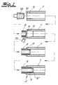
- Fig. 1 shows a straight fitting 1 made of polypropylene, which forms on both sides of a composite pipe 2, each with a composite pipe 3.
- the composite pipes 3 have an inner layer 4 and an outer layer 5 made of polypropylene, each having a thickness between 0.5 mm and 3 mm.
- Between the inner layer 4 and the outer layer 5 is a layer of metal 6, preferably aluminum or stainless steel, arranged, which has a thickness between 0.2 mm and 1.0 mm and by a first adhesive layer 7 with the inner layer 4 and with a second adhesive layer 8 is connected to the outer layer 5.
- a composite pipe 3 is inserted into the fitting 1, which surrounds each of the composite pipes 3 along a contact surface 9.
- the material of the outer layer 5 of the composite tube 3 and the inner layer 10 of the fitting 1 are fused together along the slightly conical contact surface 9 and so permanently connected.
- the inner diameter of the fitting 1 is smaller in the central region of the fitting 1 than the outer diameter of the composite pipe 3.
- the layer of metal 6 on the end face 11 of each of the composite pipes 3 inserted into the fitting 1 is characterized by an annular bead 12 made of polypropylene Insertion of the composite pipe 3 in the fitting 1 is formed, completely covered.
- Each annular bead 12 is formed of the polypropylene of the outer layers 5 of the composite pipes 3 and the inner layer 10 of the fitting 1, wherein each bead 12 is also permanently fused to the inner layer 4 of the associated composite pipe 3. Both illustrated beads 12 protrude beyond the inner layer 4 in the direction of the tube axis, although the inner diameter is not substantially reduced.
- the polypropylene as a weldable plastic is, for example, an atactic polypropylene (PP-R).
- the composite pipe 3 is inserted with its end face 11 into the fitting 1.
- a cohesive connection between the composite tube 3 and the fitting 1 is produced by melted weldable plastic and an annular bead 12 formed from the weldable plastic of the outer layer 5 of the composite tube 3 and the inner layer 10 of the fitting 1.
- the layer of metal 6 on the end face 11 of the composite tube 3 is completely covered by the annular bead 12.
- the melted weldable plastic of the outer layer 5 of the composite tube 3 and the inner layer 10 of the fitting 1 connect permanently along a contact surface 9 surrounding the end of the composite tube 3, so that after cooling the fitting 1 and the composite tube 3 permanent and pressure-resistant cable assembly. 2 arises.
Landscapes
- Engineering & Computer Science (AREA)
- Mechanical Engineering (AREA)
- General Engineering & Computer Science (AREA)
- Physics & Mathematics (AREA)
- Thermal Sciences (AREA)
- Chemical & Material Sciences (AREA)
- Combustion & Propulsion (AREA)
- Health & Medical Sciences (AREA)
- Electromagnetism (AREA)
- Toxicology (AREA)
- Lining Or Joining Of Plastics Or The Like (AREA)
- Rigid Pipes And Flexible Pipes (AREA)
Abstract
Description
- Die Erfindung betrifft einen Leitungsverbund zwischen einem Fitting und einem Verbundrohr, insbesondere für die Sanitär- und Heizungsinstallation, wobei das Verbundrohr eine Innenschicht und eine Außenschicht aus einem schweißbaren Kunststoff mit einer dazwischen angeordneten Schicht aus Metall aufweist, sowie ein Verfahren zur Herstellung eines Leitungsverbundes. Schweißbare Kunststoffe sind insbesondere Polyethylen, Polypropylen und Polybuten.
- Verbundrohre mit Schichten aus Metall und Polymeren sind aus der Praxis bekannt. Derartige Verbundrohre für die Sanitär- und Heizungsinstallation weisen eine zwischen Polymerschichten angeordnete Metallschicht auf, die vornehmlich als mechanische Verstärkung dient. Zur Erstellung eines Leitungssystems werden die Verbundrohre mit Fittings aneinandergefügt, wobei die Verbundrohre durch Verklebung oder Verschweißen druckfest mit den Fittings verbunden werden können. Um bei der Verbindung eines Verbundrohres mit einem Fitting einen Kontakt der Schicht aus Metall mit dem in dem Verbundrohr geförderten Medium und eine damit verbundene Oxidation der Metallschicht zuverlässig zu verhindern, wird vor der Verbindung die äußere Hülle der Verbundrohre einschließlich der Schicht aus Metall entfernt, was zu einem großen Zeitaufwand bei der Montage führt.
- Aus der Praxis ist weiterhin bekannt, Rohre und Fittings, die ausschließlich aus Polymeren bestehen, durch Erwärmung zu verbinden, wobei die Kontaktfläche zwischen Polymerrohr und Fitting aufgeschmolzen wird und sich die Materialien des Polymerrohres und des Fittings dauerhaft binden.
- Aus
DE 44 44 097 A1 ist ein Fitting zum Verbinden von Verbundrohren bekannt, die eine Innenschicht sowie eine Außenschicht aus einem schweißbaren Kunststoff und eine dazwischen angeordnete Schicht aus Metall aufweisen. - Das Fitting besteht aus einem Kunststoffkörper, in den ein elektrisches Widerstandsheizelement eingebettet ist. Der Kunststoffkörper weist hülsenförmige Einsteckabschnitte und eine die Einsteckabschnitte begrenzende ringförmige Rippe auf, die Stoßflächen für die einzuführenden Verbundrohre bilden. Innerhalb der Rippe sind Heizwendel des Widerstandsheizelementes angeordnet. Durch Bestromung des Widerstandsheizelementes wird das Fitting mit den Rohren verschweißt, wobei die ringförmige Rippe teilweise aufgeschmolzen wird und die Stirnflächen der Rohre umschließt. Das Fitting ist fertigungstechnisch aufwendig. Beim Verbinden der Rohre und des Fittings ist darauf zu achten, dass die Stirnflächen des Rohres während der Bestromung des Widerstandsheizelementes fest an der ringförmigen Rippe des Fittings anliegen. Nur dann entsteht ein ordnungsgemäßer Verbund und ist gewährleistet, dass die an der Stirnseite des Verbundrohres freiliegende Metallschicht nicht mit Fluid in Berührung kommt.
- Vor diesem Hintergrund liegt der Erfindung die Aufgabe zugrunde, einen dauerhaften Leitungsverbund zwischen einem Fitting und einem Verbundrohr anzugeben, der bei einer Minimierung der Arbeitsschritte eine schnelle und sichere Montage ermöglicht, wobei jeglicher Kontakt der an der Stirnseite des Verbundrohres freiliegenden Metallschicht mit Fluid, welches den Leitungsverbund durchströmt, vermieden werden soll. Das Fitting soll einen konstruktiv einfachen Aufbau aufweisen und sich kostengünstig fertigen lassen.
- Die Aufgabe wird erfindungsgemäß durch einen Leitungsverbund zwischen einem Fitting und einem Verbundrohr, insbesondere für die Sanitär- und Heizungsinstallation, gelöst, wobei das Verbundrohr eine Innenschicht und eine Außenschicht aus einem schweißbaren Kunststoff mit einer dazwischen angeordneten Schicht aus Metall aufweist, die in Richtung der Rohrinnenseite durch eine erste Klebstoffschicht mit der Innenschicht und in Richtung der Rohraußenseite durch eine zweite Klebstoffschicht mit der Außenschicht verbunden ist, wobei ein Ende des Verbundrohres in das Fitting, welches das Verbundrohr entlang einer Kontaktfläche umgibt und eine innere Schicht aus einem schweißbaren Kunststoff aufweist, eingesteckt ist, wobei das Verbundrohr und das Fitting durch Aufschmelzen der aus schweißbarem Kunststoff bestehenden Kontaktfläche stoffschlüssig verbunden sind, und wobei die Metallschicht an der Stirnseite des in das Fitting eingesetzten Verbundrohres durch eine ringförmige Wulst aus schweißbarem Kunststoff, die beim Einsetzen des Rohres in das Fitting entsteht, vollständig abgedeckt ist. Die ringförmige Wulst ist aus dem Material des Fittings und/oder dem Material der Außenschicht des Verbundrohres gebildet und trennt die an der Stirnseite des Verbundrohres freiliegende Metallschicht von dem fluiddurchströmten Raum des Leitungsverbundes. Sie entsteht durch Kontakt und Materialverdrängung beim Einschieben des Verbundrohres in das Fitting. Geeignete schweißbare Kunststoffe sind vorzugsweise Polyethylen, Polypropylen oder Polybuten.
- Die Fittings, die in einer bevorzugten Ausführung der Erfindung vollständig aus schweißbarem Kunststoff, insbesondere Polyethylen, Polypropylen oder Polybuten bestehen und so kostengünstig zu fertigen sind, können als gerade oder abgewinkelte Stücke zur Verbindung von zwei Verbundrohren oder als Abzweig- und T-Stücke zur Verbindung von mehr als zwei Verbundrohren ausgebildet sein. Sie enthalten keine integrierten Widerstandsheizeinrichtungen. Im Rahmen der Erfindung können die Fittings Anschlussenden von Regel- und/oder Absperrventilen sein. In einer bevorzugten Ausführung der Erfindung ist der Öffnungsbereich des Fittings, in welches das Verbundrohr eingesteckt ist, konisch erweitert.
- Der Außendurchmesser der Verbundrohre und der Innendurchmesser der die Verbundrohre aufnehmenden Fittings liegen beispielsweise in einem Bereich zwischen 12 mm und 63 mm. Vorzugsweise weist die Innenschicht und/oder die Außenschicht des Verbundrohres aus schweißbarem Kunststoff eine Dicke zwischen 0,5 mm und 3 mm auf. Die Schicht aus Metall weist vorzugsweise eine Dicke von 0,2 mm und 1,0 mm auf und ist jeweils mit einer Klebstoffschicht mit der Innenschicht und der Außenschicht verbunden. Die Klebstoffschichten, die beispielsweise von einem Hotmeltklebstoff gebildet werden, sind üblicherweise deutlich dünner als die weiteren Schichten des Verbundrohres. Als Material für die Schicht aus Metall ist im besonderen Maße Aluminium oder rostfreier Stahl geeignet.
- Die ringförmige Wulst, die beim Einsetzen des Rohres in das Fitting durch Kontakt und Materialverdrängung von thermoplastifiziertem Kunststoff entsteht und aus dem Material der Außenschicht des Verbundrohres und/oder der inneren Schicht des Fittings gebildet ist, kann über die Innenschicht hinaus etwas in das Innere des Verbundrohres vorstehen, wobei jedoch der Rohrquerschnitt nicht wesentlich reduziert wird. Die Wulst ist entlang ihres Umfanges mit der Innenschicht verschmolzen.
- Das für den Leitungsverbund eingesetzte Verbundrohr weist vorzugsweise einen Längenausdehnungskoeffizienten in Längsrichtung auf, der in einem Temperaturbereich zwischen 20 °C und 90 °C kleiner als 1 x 10⁻⁴K-1, besonders bevorzugt kleiner als 4 x 10⁻⁵K-1 ist. Insbesondere können auch Verbundrohre eingesetzt werden, die eine Druckfestigkeit von mindestens 15 bar bei 70 °C und einen Biegeradius aufweisen, der kleiner ist als das Zehnfache des Durchmessers des Verbundrohres. Das Verbundrohr ist vornehmlich für Warmwasseranwendungen bis 95 °C bestimmt.
- Gegenstand der Erfindung ist auch ein Verfahren zur Herstellung eines zuvor beschriebenen Leitungsverbundes zwischen einem Fitting und einem Verbundrohr, insbesondere für die Sanitär- und Heizungsinstallation, wobei das Fitting, welches zumindest eine innere Schicht aus einem schweißbaren Kunststoff aufweist, und das Verbundrohr, welches eine zwischen einer Innenschicht und einer Außenschicht aus schweißbarem Kunststoff angeordnete Schicht aus Metall aufweist, in einem Verbindungsbereich erwärmt werden, wodurch im Verbindungsbereich zumindest der schweißbare Kunststoff der Außenschicht des Verbundrohres und der inneren Schicht des Fittings erweicht wird, wobei das Verbundrohr mit einer Stirnseite in das Fitting eingeschoben wird, und dabei durch aufgeschmolzenen schweißbaren Kunststoff eine stoffschlüssige Verbindung zwischen dem Verbundrohr und dem Fitting hergestellt wird sowie eine ringförmige Wulst aus dem schweißbaren Kunststoff der Außenschicht des Verbundrohres und/oder der Innenschicht des Fittings gebildet wird, welche die Schicht aus Metall an der Stirnseite des Verbundrohres vollständig abdeckt.
- In einer bevorzugten Ausführung der Erfindung werden die Innenseite des Fittings und/oder die Außenseite des Verbundrohres in dem Bereich, in dem das Verbundrohr in das Fitting eingeschoben wird, vor der Verbindung mechanisch bearbeitet. So kann beispielsweise der Öffnungsbereich des Fittings, in welches das Verbundrohr eingeschoben wird, vor der Erwärmung durch Schleifen oder Zerspanen konisch erweitert werden. Durch die Erweiterung des Innendurchmessers in dem Öffnungsbereich des Fittings, in welches das Verbundrohr eingeschoben wird, wird einerseits eine oberflächliche Oxidschicht entfernt, wodurch die Festigkeit der Schmelzverbindung der Kontaktfläche verbessert und das Einschieben des Verbundrohres in das Fitting erleichtert wird. Des Weiteren kann durch den Winkel des Konus die Schmelzeverteilung beeinflusst werden.
- Im Folgenden wird die Erfindung anhand einer lediglich ein Ausführungsbeispiel darstellenden Zeichnung ausführlich erläutert. Es zeigen schematisch:
- Fig. 1
- eine Schnittdarstellung eines erfindungsgemäßen Leitungsverbundes zwischen einem Fitting und einem Verbundrohr und
- Fig. 2
- die Verfahrensschritte zur Herstellung eines erfindungsgemäßen Leitungsverbundes, wobei ein Verbundrohr und ein Fitting in einem Schnitt dargestellt sind.
- Die Fig. 1 zeigt ein gerades Fitting 1 aus Polypropylen, welches beidseitig einen Leitungsverbund 2 mit jeweils einem Verbundrohr 3 bildet. Die Verbundrohre 3 weisen eine Innenschicht 4 und eine Außenschicht 5 aus Polypropylen mit jeweils einer Dicke zwischen 0,5 mm und 3 mm auf. Zwischen der Innenschicht 4 und der Außenschicht 5 ist eine Schicht aus Metall 6, vorzugsweise Aluminium oder rostfreiem Stahl, angeordnet, die eine Dicke zwischen 0,2 mm und 1,0 mm aufweist und durch eine erste Klebstoffschicht 7 mit der Innenschicht 4 und mit einer zweiten Klebstoffschicht 8 mit der Außenschicht 5 verbunden ist. Jeweils ein Ende eines Verbundrohres 3 ist in das Fitting 1, welches jedes der Verbundrohre 3 entlang einer Kontaktfläche 9 umgibt, eingesteckt. Das Material der Außenschicht 5 des Verbundrohres 3 und der inneren Schicht 10 des Fittings 1 sind entlang der leicht konisch verlaufenden Kontaktfläche 9 miteinander verschmolzen und so dauerhaft verbunden. Der Innendurchmesser des Fittings 1 ist in dem mittleren Bereich des Fittings 1 kleiner als der Außendurchmesser des Verbundrohres 3. Die Schicht aus Metall 6 an der Stirnseite 11 jedes der in das Fitting 1 eingesetzten Verbundrohre 3 ist durch eine ringförmige Wulst 12 aus Polypropylen, die beim Einsetzen des Verbundrohres 3 in das Fitting 1 entsteht, vollständig abgedeckt. Jede ringförmige Wulst 12 ist aus dem Polypropylen der Außenschichten 5 der Verbundrohre 3 und der inneren Schicht 10 des Fittings 1 gebildet, wobei jede Wulst 12 auch mit der Innenschicht 4 des zugehörigen Verbundrohres 3 dauerhaft verschmolzen ist. Beide dargestellten Wülste 12 ragen in Richtung der Rohrachse über die Innenschicht 4 hinaus, wobei jedoch der Innendurchmesser nicht wesentlich reduziert ist. Bei dem Polypropylen als schweißbaren Kunststoff handelt es sich beispielsweise um ein ataktisches Polypropylen (PP-R).
- Wie in Fig. 2 dargestellt, wird bei der Herstellung eines Leitungsverbundes 2 die Innenseite des Fittings 1 in dem Bereich, in dem das Verbundrohr 3 in das Fitting 1 eingeschoben wird, vor der Verbindung mechanisch verarbeitet. Mit einem konisch geformten Schleifenwerkzeug 13 wird eine dünne Materialschicht in dem Öffnungsbereich 14 des Fittings 1 abgetragen. Durch die Entfernung der möglicherweise verschmutzten oder oxidierten Materialschicht wird eine verbesserte Verbindung mit dem Verbundrohr 3 erreicht. Zusätzlich wird durch eine konische Erweiterung des Öffnungsbereiches 14 das nachfolgende Einschieben des Verbundrohres 3 erleichtert. Anschließend an die mechanische Bearbeitung des Fittings 1 werden Fitting 1 und Verbundrohre 3 mittels einer Heizeinrichtung 15 in einem Abschnitt, der den späteren Verbindungsbereich bildet, erwärmt, wodurch der schweißbare Kunststoff der Innenschicht 4, der Außenschicht 6 und des Fittings 1 erweicht wird. Darauf folgend wird das Verbundrohr 3 mit seiner Stirnseite 11 in das Fitting 1 eingeschoben. Dabei wird durch aufgeschmolzenen schweißbaren Kunststoff eine stoffschlüssige Verbindung zwischen dem Verbundrohr 3 und dem Fitting 1 hergestellt sowie eine ringförmige Wulst 12 aus dem schweißbaren Kunststoff der Außenschicht 5 des Verbundrohres 3 und der inneren Schicht 10 des Fittings 1 gebildet. Bei einem weiteren Einschieben des Verbundrohres 3 wird die Schicht aus Metall 6 an der Stirnseite 11 des Verbundrohres 3 durch die ringförmige Wulst 12 vollständig abgedeckt. Der aufgeschmolzene schweißbare Kunststoff der Außenschicht 5 des Verbundrohres 3 und das der inneren Schicht 10 des Fittings 1 verbinden sich entlang einer das Ende des Verbundrohres 3 umgebenden Kontaktfläche 9 dauerhaft, so dass ein nach Erkalten des Fittings 1 und des Verbundrohres 3 dauerhafter und druckfester Leitungsverbund 2 entsteht.
Claims (11)
- Leitungsverbund (2) zwischen einem Fitting (1) und einem Verbundrohr (3), insbesondere für die Sanitär- und Heizungsinstallation,
wobei das Verbundrohr (3) eine Innenschicht (4) und eine Außenschicht (5) aus einem schweißbaren Kunststoff mit einer dazwischen angeordneten Schicht aus Metall (6) aufweist, die in Richtung der Rohrinnenseite durch eine erste Klebstoffschicht (7) mit der Innenschicht (4) und in Richtung der Rohraußenseite durch eine zweite Klebstoffschicht (8) mit der Außenschicht (5) verbunden ist,
wobei ein Ende des Verbundrohres (3) in das Fitting (1), welches das Verbundrohr (3) entlang einer Kontaktfläche (9) umgibt und eine innere Schicht (10) aus einem schweißbaren Kunststoff aufweist, eingesteckt ist,
wobei das Verbundrohr (3) und das Fitting (1) durch Aufschmelzen der aus schweißbarem Kunststoff bestehenden Kontaktfläche (9) stoffschlüssig verbunden sind und
wobei die Schicht aus Metall (6) an der Stirnseite (11) des in das Fitting (1) eingesetzten Verbundrohres (3) durch eine ringförmige Wulst (12) aus schweißbarem Kunststoff, die beim Einsetzen des Verbundrohres (3) in das Fitting (1) entsteht, vollständig abgedeckt ist. - Leitungsverbund (2) nach Anspruch 1, dadurch gekennzeichnet, dass das Fitting (1) vollständig aus einem schweißbaren Kunststoff besteht.
- Leitungsverbund (2) nach Anspruch 1 oder 2, dadurch gekennzeichnet, dass der schweißbare Kunststoff aus Polyethylen, Polypropylen oder Polybuten besteht.
- Leitungsverbund (2) nach einem der Ansprüche 1 bis 3, dadurch gekennzeichnet, dass die Innenschicht (4) des Verbundrohres eine Dicke zwischen 0,5 und 3 mm aufweist.
- Leitungsverbund (2) nach einem der Ansprüche 1 bis 4, dadurch gekennzeichnet, dass die Außenschicht (5) des Verbundrohres eine Dicke zwischen 0,5 und 3 mm aufweist.
- Leitungsverbund (2) nach einem der Ansprüche 1 bis 5, dadurch gekennzeichnet, dass die Schicht aus Metall (6) eine Dicke zwischen 0,2 und 1,0 mm aufweist.
- Leitungsverbund (2) nach einem der Ansprüche 1 bis 6, dadurch gekennzeichnet, dass die Schicht aus Metall (6) aus Aluminium oder rostfreiem Stahl besteht.
- Leitungsverbund (2) nach einem der Ansprüche 1 bis 7, dadurch gekennzeichnet, dass der Öffnungsbereich (14) des Fittings (1), in welches das Verbundrohr (3) eingesteckt ist, konisch erweitert ist.
- Verfahren zur Herstellung eines Leitungsverbundes (2) zwischen einem Fitting (1) und einem Verbundrohr (3), insbesondere für die Sanitär- und Heizungsinstallation, nach einem der Ansprüche 1 bis 7,
wobei das Fitting (1), welches zumindest eine innere Schicht (10) aus einem schweißbaren Kunststoff aufweist, und das Verbundrohr (3), welches eine zwischen einer Innenschicht (4) und einer Außenschicht (5) aus schweißbarem Kunststoff angeordnete Schicht aus Metall (6) aufweist, in einem Verbindungsbereich erwärmt werden, wodurch im Verbindungsbereich zumindest der schweißbare Kunststoff der Außenschicht (5) des Verbundrohres (3) und der inneren Schicht (10) des Fittings (1) erweicht wird,
wobei das Verbundrohr (3) mit einer Stirnseite (11) in das Fitting (1) eingeschoben wird und dabei durch aufgeschmolzenen schweißbaren Kunststoff eine stoffschlüssige Verbindung zwischen dem Verbundrohr (3) und dem Fitting (1) hergestellt wird sowie
außerdem eine ringförmige Wulst (12) aus dem schweißbaren Kunststoff der Außenschicht (5) des Verbundrohres (3) und/oder der inneren Schicht (10) des Fittings (1) gebildet wird, welche die Schicht aus Metall (6) an der Stirnseite (11) des Verbundrohres (3) vollständig abdeckt. - Verfahren nach Anspruch 9, dadurch gekennzeichnet, dass die Innenseite des Fittings (1) und/oder die Außenseite des Verbundrohres (3) in dem Bereich, in dem das Verbundrohr (3) in das Fitting (1) eingeschoben wird, vor der Verbindung mechanisch bearbeitet werden.
- Verfahren nach Anspruch 10, dadurch gekennzeichnet, dass der Öffnungsbereich (14) des Fittings (1), in welches das Verbundrohr (3) eingeschoben wird, vor der Erwärmung durch Schleifen oder Zerspanen konisch erweitert wird.
Applications Claiming Priority (1)
| Application Number | Priority Date | Filing Date | Title |
|---|---|---|---|
| DE102005038472A DE102005038472B4 (de) | 2005-08-13 | 2005-08-13 | Leitungsverbund zwischen einem Fitting und einem Verbundrohr sowie ein Verfahren zur Herstellung des Leitungsverbundes |
Publications (2)
| Publication Number | Publication Date |
|---|---|
| EP1752699A2 true EP1752699A2 (de) | 2007-02-14 |
| EP1752699A3 EP1752699A3 (de) | 2010-09-08 |
Family
ID=37116186
Family Applications (1)
| Application Number | Title | Priority Date | Filing Date |
|---|---|---|---|
| EP06016782A Withdrawn EP1752699A3 (de) | 2005-08-13 | 2006-08-11 | Leitungsverbund zwischen einem Fitting und einem Verbundrohr sowie ein Verfahren zur Herstellung des Leitungsverbundes |
Country Status (2)
| Country | Link |
|---|---|
| EP (1) | EP1752699A3 (de) |
| DE (1) | DE102005038472B4 (de) |
Cited By (7)
| Publication number | Priority date | Publication date | Assignee | Title |
|---|---|---|---|---|
| CN102022588A (zh) * | 2010-08-27 | 2011-04-20 | 广东联塑科技实业有限公司 | 一种衬塑钢塑复合管及其制造方法 |
| CN103470913B (zh) * | 2013-07-05 | 2016-04-27 | 周立超 | 金属玻璃钢内衬橡塑海底管线的连接结构及制作连接方法 |
| CN113606414A (zh) * | 2021-07-29 | 2021-11-05 | 山东东宏管业股份有限公司 | 一种钢丝网骨架聚乙烯复合管端头连接结构及方法 |
| CN113898792A (zh) * | 2021-11-02 | 2022-01-07 | 深圳市施威德自动化科技有限公司 | 一种双层的两种材料复合的输送管 |
| CN113958778A (zh) * | 2021-09-27 | 2022-01-21 | 安源管道实业股份有限公司 | 一种钢骨架塑料复合管 |
| CN115342238A (zh) * | 2021-05-12 | 2022-11-15 | 中国石油化工股份有限公司 | 一种管道耐高温嵌入式复合管 |
| CN115711332A (zh) * | 2022-12-05 | 2023-02-24 | 广东东方管业有限公司 | 一种用于钢丝网缠绕聚乙烯复合管的连接结构及连接方法 |
Families Citing this family (3)
| Publication number | Priority date | Publication date | Assignee | Title |
|---|---|---|---|---|
| DE102010027868B4 (de) * | 2010-04-16 | 2015-01-22 | Henze Gmbh Kunststoffwerk | Kunststoffrohr |
| DE102010047985A1 (de) * | 2010-10-08 | 2012-04-12 | Franz-Josef Riesselmann | Verfahren zum Verbinden eines Anschlussrohres mit einem Versorgungsrohr |
| DE102011108603A1 (de) | 2011-07-27 | 2013-01-31 | Friatec Aktiengesellschaft | Verbundkomponenten-Koppelsystem und Verfahren zum Vorbereiten der Kopplung einer Verbundkomponente an eine weitere Komponente |
Citations (1)
| Publication number | Priority date | Publication date | Assignee | Title |
|---|---|---|---|---|
| DE4444097A1 (de) | 1994-12-10 | 1996-06-13 | Unicor Rohrsysteme Gmbh | Einrichtung zum Verbinden von mindestens zwei Kunststoff-Metall-Verbundrohren durch Verschweißen |
Family Cites Families (2)
| Publication number | Priority date | Publication date | Assignee | Title |
|---|---|---|---|---|
| DE19961047C2 (de) * | 1999-12-16 | 2002-06-13 | Andre Anschuetz | Verfahren zum Anschluß eines Mehrschichtverbundrohres und Verbindungsstelle sowie Bauteil zur Erwärmung der Materialschichten eines Mehrschichtverbundrohres |
| AR039223A1 (es) * | 2003-04-02 | 2005-02-09 | Eduardo Felipe May | Un dispositivo para la union por termofusion de un tubo termoplastico que incluye una capa metalica intermedia entre dos capas termoplasticas, con una conexion termoplastica |
-
2005
- 2005-08-13 DE DE102005038472A patent/DE102005038472B4/de not_active Expired - Fee Related
-
2006
- 2006-08-11 EP EP06016782A patent/EP1752699A3/de not_active Withdrawn
Patent Citations (1)
| Publication number | Priority date | Publication date | Assignee | Title |
|---|---|---|---|---|
| DE4444097A1 (de) | 1994-12-10 | 1996-06-13 | Unicor Rohrsysteme Gmbh | Einrichtung zum Verbinden von mindestens zwei Kunststoff-Metall-Verbundrohren durch Verschweißen |
Cited By (9)
| Publication number | Priority date | Publication date | Assignee | Title |
|---|---|---|---|---|
| CN102022588A (zh) * | 2010-08-27 | 2011-04-20 | 广东联塑科技实业有限公司 | 一种衬塑钢塑复合管及其制造方法 |
| CN103470913B (zh) * | 2013-07-05 | 2016-04-27 | 周立超 | 金属玻璃钢内衬橡塑海底管线的连接结构及制作连接方法 |
| CN115342238A (zh) * | 2021-05-12 | 2022-11-15 | 中国石油化工股份有限公司 | 一种管道耐高温嵌入式复合管 |
| CN113606414A (zh) * | 2021-07-29 | 2021-11-05 | 山东东宏管业股份有限公司 | 一种钢丝网骨架聚乙烯复合管端头连接结构及方法 |
| CN113606414B (zh) * | 2021-07-29 | 2023-02-03 | 山东东宏管业股份有限公司 | 一种钢丝网骨架聚乙烯复合管端头连接结构及方法 |
| CN113958778A (zh) * | 2021-09-27 | 2022-01-21 | 安源管道实业股份有限公司 | 一种钢骨架塑料复合管 |
| CN113898792A (zh) * | 2021-11-02 | 2022-01-07 | 深圳市施威德自动化科技有限公司 | 一种双层的两种材料复合的输送管 |
| CN115711332A (zh) * | 2022-12-05 | 2023-02-24 | 广东东方管业有限公司 | 一种用于钢丝网缠绕聚乙烯复合管的连接结构及连接方法 |
| CN115711332B (zh) * | 2022-12-05 | 2023-05-16 | 广东东方管业有限公司 | 一种用于钢丝网缠绕聚乙烯复合管的连接结构及连接方法 |
Also Published As
| Publication number | Publication date |
|---|---|
| DE102005038472B4 (de) | 2009-02-05 |
| EP1752699A3 (de) | 2010-09-08 |
| DE102005038472A1 (de) | 2007-04-12 |
Similar Documents
| Publication | Publication Date | Title |
|---|---|---|
| DE60023502T2 (de) | Schweissmuffe mit verstärkung für kunststoffrohre | |
| DE102008024360A1 (de) | Rohrpresskupplung, insbesondere für Mehrschichtverbundrohre, sowie Verpressungsverfahren | |
| DE102005038472B4 (de) | Leitungsverbund zwischen einem Fitting und einem Verbundrohr sowie ein Verfahren zur Herstellung des Leitungsverbundes | |
| WO2012028262A1 (de) | Mehrschichtiges kunststoffrohr, dessen verwendung sowie dieses umfassende schweissverbindung | |
| EP2172328A1 (de) | Induktionsverbindungsmuffe zum Schmelzverbinden schweißbarer Thermoplastkörper | |
| DE68922648T2 (de) | Verfahren zum Verbinden von Gegenständen aus Polyolefin. | |
| DE69709872T2 (de) | Elektroschweisskupplungsvorrichtung | |
| EP4194735A1 (de) | Doppelrohrsystem | |
| DE69020894T2 (de) | Verfahren zum verbinden von rohrartigen kunststoffgegenständen durch verschmelzen. | |
| DE102007041377A1 (de) | Kunststoff-Metall-Verbundrohrsystem | |
| CH683026A5 (de) | Schweissmuffe für Kunststoffrohre. | |
| CH674890A5 (de) | ||
| DE102007042806A1 (de) | Verfahren zum Verschweißen von Kunststoffrohren | |
| DE102009048578B4 (de) | Verbindungselement zum Verschweißen von Kunststoffrohren | |
| EP3298316B1 (de) | Flanschverbindung für bauteile aus kunststoff, insbesondere für rohrförmige bauteile aus kunststoff | |
| EP4163532B1 (de) | Druckrohrmuffenverbindung | |
| EP0305462B1 (de) | Vorrichtung zum verschweissen rohrförmiger kunststoffteile | |
| EP2194303A1 (de) | Medienführendes Bauelement zur Umlenkung eines Medienstroms | |
| DE202005012830U1 (de) | Leitungsverbund zwischen einem Fitting und einem Verbundrohr | |
| DE19913836C2 (de) | Verfahren zur Herstellung einer Rohrverbindung sowie Rohrverbindung | |
| DE69510770T2 (de) | Rohrverbindung und Verfahren zur seiner Herstellung | |
| DE69601273T2 (de) | Verbesserungen an oder bezüglich Rohrverbindungen | |
| DE2363727A1 (de) | Schweissbare rohrfittings aus kunststoff | |
| EP1923615B1 (de) | Metallischer Rohrverbinder | |
| EP1614952A1 (de) | Kupplung, Leitung, Anordnung derselben, Verfahren zu deren Herstellung sowie Verfahren zum Verbinden und Lösen von Leitungen |
Legal Events
| Date | Code | Title | Description |
|---|---|---|---|
| PUAI | Public reference made under article 153(3) epc to a published international application that has entered the european phase |
Free format text: ORIGINAL CODE: 0009012 |
|
| AK | Designated contracting states |
Kind code of ref document: A2 Designated state(s): AT BE BG CH CY CZ DE DK EE ES FI FR GB GR HU IE IS IT LI LT LU LV MC NL PL PT RO SE SI SK TR |
|
| AX | Request for extension of the european patent |
Extension state: AL BA HR MK YU |
|
| PUAL | Search report despatched |
Free format text: ORIGINAL CODE: 0009013 |
|
| AK | Designated contracting states |
Kind code of ref document: A3 Designated state(s): AT BE BG CH CY CZ DE DK EE ES FI FR GB GR HU IE IS IT LI LT LU LV MC NL PL PT RO SE SI SK TR |
|
| AX | Request for extension of the european patent |
Extension state: AL BA HR MK RS |
|
| AKY | No designation fees paid | ||
| STAA | Information on the status of an ep patent application or granted ep patent |
Free format text: STATUS: THE APPLICATION IS DEEMED TO BE WITHDRAWN |
|
| 18D | Application deemed to be withdrawn |
Effective date: 20110309 |