EP1752605A2 - Laufwagen für eine Vertikaljalousie - Google Patents
Laufwagen für eine Vertikaljalousie Download PDFInfo
- Publication number
- EP1752605A2 EP1752605A2 EP06118641A EP06118641A EP1752605A2 EP 1752605 A2 EP1752605 A2 EP 1752605A2 EP 06118641 A EP06118641 A EP 06118641A EP 06118641 A EP06118641 A EP 06118641A EP 1752605 A2 EP1752605 A2 EP 1752605A2
- Authority
- EP
- European Patent Office
- Prior art keywords
- stop
- axial direction
- carriage according
- drive means
- drive sleeve
- Prior art date
- Legal status (The legal status is an assumption and is not a legal conclusion. Google has not performed a legal analysis and makes no representation as to the accuracy of the status listed.)
- Granted
Links
- 241000446313 Lamella Species 0.000 claims abstract description 16
- 230000001066 destructive effect Effects 0.000 abstract description 2
- 230000018109 developmental process Effects 0.000 description 3
- 230000003993 interaction Effects 0.000 description 3
- 241000237858 Gastropoda Species 0.000 description 1
- 230000012447 hatching Effects 0.000 description 1
- 238000001746 injection moulding Methods 0.000 description 1
- 238000004519 manufacturing process Methods 0.000 description 1
- 230000000475 sunscreen effect Effects 0.000 description 1
- 239000000516 sunscreening agent Substances 0.000 description 1
Images



Classifications
-
- E—FIXED CONSTRUCTIONS
- E06—DOORS, WINDOWS, SHUTTERS, OR ROLLER BLINDS IN GENERAL; LADDERS
- E06B—FIXED OR MOVABLE CLOSURES FOR OPENINGS IN BUILDINGS, VEHICLES, FENCES OR LIKE ENCLOSURES IN GENERAL, e.g. DOORS, WINDOWS, BLINDS, GATES
- E06B9/00—Screening or protective devices for wall or similar openings, with or without operating or securing mechanisms; Closures of similar construction
- E06B9/24—Screens or other constructions affording protection against light, especially against sunshine; Similar screens for privacy or appearance; Slat blinds
- E06B9/26—Lamellar or like blinds, e.g. venetian blinds
- E06B9/36—Lamellar or like blinds, e.g. venetian blinds with vertical lamellae ; Supporting rails therefor
- E06B9/362—Travellers; Lamellae suspension stems
- E06B9/364—Operating mechanisms therein
-
- E—FIXED CONSTRUCTIONS
- E06—DOORS, WINDOWS, SHUTTERS, OR ROLLER BLINDS IN GENERAL; LADDERS
- E06B—FIXED OR MOVABLE CLOSURES FOR OPENINGS IN BUILDINGS, VEHICLES, FENCES OR LIKE ENCLOSURES IN GENERAL, e.g. DOORS, WINDOWS, BLINDS, GATES
- E06B9/00—Screening or protective devices for wall or similar openings, with or without operating or securing mechanisms; Closures of similar construction
- E06B9/24—Screens or other constructions affording protection against light, especially against sunshine; Similar screens for privacy or appearance; Slat blinds
- E06B9/26—Lamellar or like blinds, e.g. venetian blinds
- E06B9/36—Lamellar or like blinds, e.g. venetian blinds with vertical lamellae ; Supporting rails therefor
- E06B9/362—Travellers; Lamellae suspension stems
Definitions
- the invention relates to a carriage for a vertical blind with a housing, a rotatably mounted in the housing about its longitudinal axis lamellar hook which is driven in rotation by means of drive means, and with a stop which prevents rotation of the lamellar hook beyond a basic position.
- Such vertical blinds are used for shading or privacy.
- a continuous shaft is provided, on which the carriages are arranged longitudinally displaceable and by means of which the drive means for the lamella hooks are driven.
- This drive shaft is usually used to adjust the angle of attack of the individual vertical slats.
- Monogetriebes it can occur when approaching the vertical blind when hitting an obstacle, such as a flower pot in the windowsill, that make these vertical slats at an angle and the vertical blind can not be approached. If the mono gear is then actuated in the opposite direction to the opening of the vertical blind, the individual slats first pivot into their end position, before the slats then back to a Package to be driven together.
- the problem underlying the invention is to provide a carriage for a vertical blind in which a malposition of a blade can be easily and non-destructively repair.
- the problem is solved in that cooperates in a carriage of the type mentioned in the stop with the drive means for aligning the lamellar hook in the basic position.
- a targeted driving of the lamellar hook can be used by means of the drive means against the stop for returning a worm wheel in the desired position and thus for aligning the failed lamella.
- the drive means comprise a drive sleeve with a sprocket portion on at least a part of the outer circumference and a worm wheel with at least one gear of a worm outer thread.
- These drive means are simple and inexpensive to manufacture by injection molding.
- the worm wheel can be driven by means of a drive shaft.
- a front end of the worm gear cooperates with a stop surface arranged adjacent to the toothed rim section on the outer circumference of the drive sleeve.
- the abutment of the front end on the stop surface in this case causes the stop and can be easily kinematically used for a positioning of the lamella.
- the stop surface is arranged obliquely to the axial direction of the drive sleeve.
- the angle should be smaller than at right angles to the axial direction. In this way, the front end of the abutment surface can slide when hitting the front end of the stop surface.
- the stop surface has a first portion which is inclined at a first angle to the axial direction, and a second portion which is inclined at a smaller second angle to the axial direction.
- This embodiment is particularly advantageous in automatic assembly of the vertical blinds, because in this case the first section forms a noticeable resistance with the first angle, so that the individual carriages can be positioned against this resistance.
- slippage on the first section is ensured when a predetermined force is exceeded, slippage of the drive means being ensured when the front end impinges on the second section with the smaller second angle.
- the front end of the flight of the stop surface is correspondingly oblique to the axial direction of the worm wheel. In this way, when striking the front end of the stopper portion, the front end and the stopper portion are substantially parallel to each other, so that they can slip off each other well.
- Fig. 1. shows a schematic partial representation of Veritkaljalousie with the invention features. Shown is a mounting rail 10 in which a plurality of carriages 11 are arranged. The carriages 11 each carry a lamella hook 12, which is in each case pivotable in the carriage 11. At the lower end of the lamellar hook 12, a lamella holder 13 is arranged in each case, can be hung in the not shown in the figure slats as a sunscreen or privacy.
- the individual carriages are driven via a drive shaft, not shown in the figure, for pivoting the lamella hooks. Actuates the drive shaft and the lamellar hooks by means of a monogetrieb also not shown in the figure.
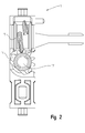
- Fig. 2 shows a schematic representation of a carriage 11.
- the carriage 11 has a drive sleeve 14 and a worm wheel 15 which engage with each other.
- the drive sleeve 14 carries the lamellar hook 12, while the worm wheel 15 can be driven in a known manner by a drive shaft, not shown in the figure to a rotation.
- the lamella hook 12 and the drive sleeve 14 may be formed integrally or separately.
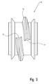
- the worm wheel 15 has a worm gear 16 which has two end faces 17, 18. In the region of the front ends 17, 18, there is an overlap of the worm thread 16. As can also be seen from the figure, the front ends 17, 18 are arranged inclined relative to the axial direction of the worm wheel 16. In detail, the inclination of the front ends 17, 18 is ten degrees against the axial direction. The inclination of the front ends 17, 18 is selected depending on the desired pressure point.
- the drive sleeve 14 has on a part of its outer circumferential surface a sprocket section 19 for interaction with the worm thread 16. Adjacent to the toothed rim section 19 on one side is a stop with a first stop section 20 and a second stop section 21.
- the first stopper portion 20 is arranged obliquely to the axial direction of the drive sleeve 14.
- the angle of the first stopper portion 20 against the axial direction is about 80 °.
- the angle of the second stopper portion 21 against the axial direction is smaller than the angle of the first stopper portion.
- Fig. 5 shows the interaction of the drive sleeve 14 and the worm wheel 15 in a first stop position.
- the front end 18 abuts on the first stop portion 20 and thus prevents further rotation of the worm wheel for rotating the drive sleeve counterclockwise.
- the front end 18 and the first stopper portion 20 collide with each other approximately parallel. This position is used to position the individual carriages in automated assembly. If the malposition of a single lamella is to be eliminated in the installed state, the worm wheel is driven by means of the drive shaft with increased force against the stop section 20. In this case, the front end 18 slides on the stopper portion 20 so far, until it gets into the region of the stopper portion 21.
- this abutment portion 21 is more inclined, that is arranged at a smaller angle to the axis of the drive sleeve, the front end 18 then slides down slightly over the abutment portion 21 in the figure, whereby the worm gear 16 in the region of the front end 17 on the adjacent tooth 22 of the ring gear 19 skips.
- FIG. 6 shows a further perspective illustration of the drive sleeve 14. Shown is a stop 23, which is arranged on the end of the toothed rim section 19 facing away from the tooth 22. The stop 23 is also arranged obliquely to the longitudinal axis of the drive sleeve 14 and closes with this a relatively small angle.
- Fig. 7 shows the interaction of the drive sleeve 14 with the worm wheel 15 in a second end position.
- the front end 17 abuts against the stop 23.
- the front end 17 slides on the stop 23, so that the worm gear 16 jumps over the adjacent tooth 24 of the sprocket section 19 in the region of the front end 18.
Landscapes
- Engineering & Computer Science (AREA)
- Structural Engineering (AREA)
- Architecture (AREA)
- Civil Engineering (AREA)
- Blinds (AREA)
- Operating, Guiding And Securing Of Roll- Type Closing Members (AREA)
Abstract
Description
- Die Erfindung betrifft einen Laufwagen für eine Vertikaljalousie mit einem Gehäuse, einem in dem Gehäuse um seine Längsachse drehbar gelagerten Lamellenhaken, der mittels Antriebsmitteln drehend antreibbar ist, und mit einem Anschlag, der ein Verdrehen des Lamellenhakens über eine Grundstellung hinaus verhindert.
- Derartige Vertikaljalousien werden zum Verschatten oder als Sichtschutz eingesetzt. Üblicherweise ist eine durchgehende Welle vorgesehen, auf der die Laufwagen längs verschiebbar angeordnet sind und mittels derer die Antriebsmittel für die Lamellenhaken angetrieben werden. Diese Antriebswelle dient üblicherweise zum Verstellen des Anstellwinkels der einzelnen Vertikallamellen. Bei der Verwendung eines sogenannten Monogetriebes kann es beim Zufahren der Vertikaljalousie beim Auftreffen auf ein Hindernis, wie beispielsweise einen Blumentopf in der Fensterbank, auftreten, dass sich diese Vertikallamellen schräg stellen und die Vertikaljalousie nicht zugefahren werden kann. Wird dann das Monogetriebe in Gegenrichtung zum Öffnen der Vertikaljalousie betätigt, schwenken die einzelnen Lamellen zunächst in ihre Endstellung, bevor die Lamellen dann wieder zu einem Paket zusammen gefahren werden. Hierbei kann es vorkommen, dass die durch das Hindernis in Schräglage befindliche Lamelle mit der Führungsnut der oberen Führungsschiene der Vertikaljalousie einfädelt und dadurch blockiert. Wird dies nicht erkannt, führt ein weiteres Betätigen des Monogetriebes zu einem Überspringen eines zum Antreiben der Lamellenhaken verwendeten Schneckenrades. Selbst wenn man jetzt die blockierte Lamelle befreit, lässt sich die durch das Überspringen des Schneckenrades resultierende Fehlstellung der Lamelle nicht mehr zerstörungsfrei beheben. Ein ähnliches Problem kann auch beim Öffnen der Vertikaljalousie auftreten.
- Das der Erfindung zugrunde liegende Problem ist es, einen Laufwagen für eine Vertikaljalousie anzugeben, bei dem sich eine Fehlstellung einer Lamelle einfach und zerstörungsfrei beheben lässt.
- Das Problem wird dadurch gelöst, dass bei einem Laufwagen der eingangs genannten Art der Anschlag mit den Antriebsmitteln zum Ausrichten des Lamellenhakens in der Grundstellung zusammenwirkt.
- Auf diese Weise kann ein gezieltes Antreiben des Lamellenhakens mittels der Antriebsmittel gegen den Anschlag zum Rückspringen eines Schneckenrades in die gewünschte Position und somit zum Ausrichten der fehl gestellten Lamelle verwendet werden.
- Bei einer Weiterbildung der Erfindung bewirkt der Anschlag bei einem Antreiben des Lamellenhakens über die Grundstellung hinaus ein Durchrutschen der Antriebsmittel. Dadurch lässt sich zerstörungsfrei die erwünschte Positionierung der Lamelle erzielen.
- Eine andere Weiterbildung zeichnet sich dadurch aus, dass die Antriebsmittel eine Antriebshülse mit einem Zahnkranzabschnitt auf zumindest einem Teil des Außenumfangs und ein Schneckenrad mit mindestens einem Gang eines Schneckenaußengewindes aufweisen. Diese Antriebsmittel sind im Spritzgussverfahren einfach und kostengünstig herzustellen. Das Schneckenrad kann mittels einer Antriebswelle angetrieben werden.
- Es ist dabei vom Vorteil, wenn ein Stirnende des Schneckenganges mit einer dem Zahnkranzabschnitt benachbart auf dem Außenumfang der Antriebshülse angeordneten Anschlagfläche zusammenwirkt. Das Anstoßen des Stirnendes auf die Anschlagfläche bewirkt in diesem Fall den Anschlag und kann einfach kinematisch für eine Positionierung der Lamelle verwendet werden. Vorzugsweise ist dabei die Anschlagfläche schräg zur Axialrichtung der Antriebshülse angeordnet.
- Der Winkel sollte dabei aber kleiner als rechtwinklig zu der Axialrichtung sein. Auf diese Weise kann beim Auftreffen des Stirnendes auf die Anschlagfläche das Stirnende von der Anschlagfläche abgleiten.
- Mit der Erfindung wird gewährleistet, dass bei einer Fehlstellung einer einzelnen Lamelle diese beim Erreichen ihrer Endstellung so lange durchrutscht, bis alle anderen Lamellen ebenfalls in der Endstellung angelangt sind. Auf diese Weise ist eine einfache Korrektur einer Fehlstellung möglich.
- Eine andere Weiterbildung zeichnet sich dadurch aus, dass die Anschlagfläche einen ersten Abschnitt, der um einen ersten Winkel gegen die Axialrichtung geneigt ist, und einen zweiten Abschnitt aufweist, der um einen kleineren zweiten Winkel gegen die Axialrichtung geneigt ist. Diese Ausführungsform ist insbesondere bei der Automatenmontage der Vertikaljalousien von Vorteil, weil dabei der erste Abschnitt mit dem ersten Winkel einen spürbaren Widerstand bildet, so dass die einzelnen Laufwagen gegen diesen Widerstand positioniert werden können. Gleichzeitig ist aber bei Überschreiten einer vorbestimmten Kraft ein Abrutschen auf dem ersten Abschnitt gewährleistet wobei beim Auftreffen des Stirnendes auf den zweiten Abschnitt mit dem kleineren zweiten Winkel ein Durchrutschen der Antriebsmittel gewährleistet wird.
- Bei der Erfindung ist es außerdem von Vorteil, dass das Stirnende des Schneckenganges der Anschlagfläche entsprechend schräg zur Axialrichtung des Schneckenrades ist. Auf diese Weise sind beim Anschlagen des Stirnendes auf den Anschlagabschnitt das Stirnende und der Anschlagabschnitt im Wesentlichen parallel zueinander, so dass diese gut aufeinander abrutschen können.
- Nachfolgend wir ein Ausführungsbeispiel der Erfindung anhand der Zeichnungen näher erläutert. Es zeigen:
- Fig.1
- eine schematische Teildarstellung einer Vertikaljalousie mit den Erfindungsmerkmalen,
- Fig. 2
- eine schematische Darstellung eines Laufwagens mit den Erfindungsmerkmalen,
- Fig. 3
- eine Darstellung eines Schneckenrades des Laufwagens von Fig. 2,
- Fig. 4
- eine Darstellung einer Antriebshülse des Laufwagens von Fig. 2,
- Fig. 5
- die Antriebshülse und das Schneckenrad in einer ersten Anschlagsstellung,
- Fig. 6
- die Antriebshülse in einer anderen Darstellung und
- Fig. 7
- die Antriebshülse und das Schneckenrad in einer zweiten Anschlagstellung.
- Fig. 1. zeigt eine schematische Teildarstellung einer Veritkaljalousie mit den Erfindungsmerkmalen. Abgebildet ist eine Tragschiene 10 in der mehrere Laufwagen 11 angeordnet sind. Die Laufwagen 11 tragen jeweils einen Lamellenhaken 12, der in den Laufwagen 11 jeweils verschwenkbar ist. Am unteren Ende des Lamellenhakens 12 ist jeweils ein Lamellenhalter 13 angeordnet, in den nicht in der Figur dargestellte Lamellen als Sonnenschutz oder Sichtschutz eingehängt werden können. Im Betrieb werden die einzelnen Laufwagen über eine nicht in der Figur dargestellte Antriebswelle zum Verschwenken der Lamellenhaken angetrieben. Betätigt werden die Antriebswelle und die Lamellenhaken mittels eines ebenfalls nicht in der Figur dargestellten Monogetriebes.
- Fig. 2 zeigt eine schematische Darstellung eines Laufwagens 11. Zur besseren Übersicht ist das Gehäuse des Laufwagens 11 im Schnitt ohne Schraffur dargestellt. Der Laufwagen 11 weist eine Antriebshülse 14 und ein Schneckenrad 15 auf, die miteinander in Eingriff stehen. Die Antriebshülse 14 trägt den Lamellenhaken 12, während das Schneckenrad 15 auf bekannte Weise von einer nicht in der Figur dargestellten Antriebswelle zu einer Drehung angetrieben werden kann. Der Lamellenhaken 12 und die Antriebshülse 14 können einstückig oder separat ausgebildet sein.
- Fig. 3 zeigt eine Darstellung des Schneckenrades 15. Wie sich der Figur entnehmen lässt, weist das Schneckenrad 15 einen Schneckengang 16 auf, der zwei Stirnenden 17, 18 hat. Im Bereich der Stirnenden 17, 18 gibt es eine Überlappung des Schneckenganges 16. Wie sich der Figur außerdem entnehmen lässt, sind die Stirnenden 17, 18 gegen die Axialrichtung des Schneckenrades 16 geneigt angeordnet. Im Einzelnen beträgt die Neigung der Stirnenden 17, 18 zehn Grad gegen die Axialrichtung. Die Neigung der Stirnenden 17, 18 wird abhängig von dem gewünschten Druckpunkt gewählt.
- Fig. 4 zeigt eine perspektivische Darstellung der Antriebshülse 14. Wie sich der Figur entnehmen lässt, weist die Antriebshülse 14 an einem Teil ihrer Außenumfangsfläche einen Zahnkranzabschnitt 19 zur Wechselwirkung mit dem Schneckengang 16 auf. Auf einer Seite dem Zahnkranzabschnitt 19 benachbart ist ein Anschlag mit einem ersten Anschlagabschnitt 20 und einem zweiten Anschlagabschnitt 21 angeordnet. Der erste Anschlagabschnitt 20 ist schräg zur Axialrichtung der Antriebshülse 14 angeordnet. Der Winkel des ersten Anschlagabschnittes 20 gegen die Axialrichtung beträgt etwa 80°. Der Winkel des zweiten Anschlagabschnittes 21 gegen die Axialrichtung ist kleiner als der Winkel des ersten Anschlagabschnittes.
- Fig. 5 zeigt die Wechselwirkung der Antriebshülse 14 und des Schneckenrades 15 in einer ersten Anschlagstellung. In dieser ersten Anschlagstellung stößt das Stirnende 18 auf den ersten Anschlagabschnitt 20 und verhindert so ein weiteres Drehen des Schneckenrades zum Rotieren der Antriebshülse gegen den Uhrzeigersinn. Das Stirnende 18 und der erste Anschlagabschnitt 20 stoßen dabei in etwa parallel aufeinander. Diese Position dient zum Positionieren der einzelnen Laufwagen bei der automatisierten Montage. Soll im montierten Zustand die Fehlstellung einer einzelnen Lamelle beseitigt werden, wird mittels der Antriebswelle das Schneckenrad mit erhöhter Kraft gegen den Anschlagabschnitt 20 angetrieben. Dabei gleitet das Stirnende 18 auf dem Anschlagabschnitt 20 so weit ab, bis es in den Bereich des Anschlagabschnittes 21 gerät. Da dieser Anschlagabschnitt 21 stärker geneigt ist, also unter einem kleineren Winkel gegen die Achse der Antriebshülse angeordnet ist, gleitet das Stirnende 18 sodann leicht über den Anschlagabschnitt 21 in der Figur nach unten hin ab, wodurch der Schneckengang 16 im Bereich des Stirnendes 17 über den benachbarten Zahn 22 des Zahnkranzes 19 überspringt.
- Fig. 6 zeigt eine weitere perspektivische Darstellung der Antriebshülse 14. Gezeigt ist ein Anschlag 23, der am von dem Zahn 22 abgewandten Ende des Zahnkranzabschnittes 19 angeordnet ist. Der Anschlag 23 ist ebenfalls schräg zur Längsachse der Antriebshülse 14 angeordnet und schließt mit dieser einen verhältnismäßig kleinen Winkel ein.
- Fig. 7 zeigt das Zusammenwirken der Antriebshülse 14 mit dem Schneckenrad 15 in einer zweiten Endstellung. In dieser zweiten Endstellung stößt das Stirnende 17 an den Anschlag 23 an. Bei einem Antreiben des Schneckenrades 15 gegen den Widerstand gleitet das Stirnende 17 auf dem Anschlag 23 ab, so dass der Schneckengang 16 im Bereich des Stirnendes 18 über den benachbarten Zahn 24 des Zahnkranzabschnittes 19 springt.
-
- 10
- Tragschiene
- 11
- Laufwagen
- 12
- Lamellenhaken
- 13
- Lamellenhalter
- 14
- Antriebshülse
- 15
- Schneckenrad
- 16
- Schneckengang
- 17
- Stirnende
- 18
- Stirnende
- 19
- Zahnkranzabschnitt
- 20
- Anschlagabschnitt
- 21
- Anschlagabschnitt
- 22
- Zahn
- 23
- Anschlag
- 24
- Zahn
Claims (7)
- Laufwagen für eine Vertikaljalousie mit einem Gehäuse, einem in dem Gehäuse um seine Längsachse drehbar gelagerten Lamellenhaken (12), der mittels Antriebsmitteln (14, 15) drehend antreibbar ist, und mit einem Anschlag (20, 21, 23), der ein Verdrehen des Lamellenhakens (12) über eine Grundstellung hinaus verhindert, dadurch gekennzeichnet, dass der Anschlag (10, 21, 23) mit den Antriebsmitteln (15) zum Ausrichten des Lamellenhakens (12) in der Grundstellung zusammenwirkt.
- Laufwagen nach Anspruch 1, dadurch gekennzeichnet, dass der Anschlag (20, 21, 23) bei einem Antreiben des Lamellenhakens (12) über die Grundstellung hinaus ein Durchrutschen der Antriebsmittel (15) bewirkt.
- Laufwagen nach Anspruch 1 oder 2, dadurch gekennzeichnet, dass die Antriebsmittel (14, 15) eine Antriebshülse (14) mit einem Zahnkranzabschnitt (19) auf zumindest einem Teil des Außenumfangs und ein Schneckenrad (15) mit mindestens einem Gang (16) eines Schneckenaußengewindes aufweist.
- Laufwagen nach Anspruch 3, dadurch gekennzeichnet, dass ein Stirnende (17, 18) des Schneckenganges (16) mit einer dem Zahnkranzabschnitt (19) benachbarten auf dem Außenumfang der Antriebshülse (14) angeordneten Anschlagfläche (20, 21, 23) zusammenwirkt.
- Laufwagen nach Anspruch 4, dadurch gekennzeichnet, dass die Anschlagfläche (20, 21, 23) schräg zur Axialrichtung der Antriebshülse (14) angeordnet ist.
- Laufwagen nach Anspruch 5, dadurch gekennzeichnet, dass die Anschlagfläche einen ersten Abschnitt (20), der um einen ersten Winkel gegen die Axialrichtung geneigt ist, und einen zweiten Abschnitt (21) aufweist, der um einen kleineren zweiten Winkel gegen die Axialrichtung geneigt ist.
- Laufwagen nach Anspruch 5 oder 6, dadurch gekennzeichnet, dass das Stirnende (17, 18) des Schneckenganges (16) der Anschlagfläche (20, 21, 23) entsprechend schräg zur Axialrichtung des Schneckenrades (15) ist.
Priority Applications (1)
| Application Number | Priority Date | Filing Date | Title |
|---|---|---|---|
| PL06118641T PL1752605T3 (pl) | 2005-08-10 | 2006-08-09 | Wózek do żaluzji pionowej |
Applications Claiming Priority (1)
| Application Number | Priority Date | Filing Date | Title |
|---|---|---|---|
| DE102005038075A DE102005038075A1 (de) | 2005-08-10 | 2005-08-10 | Laufwagen für eine Vertikaljalousie |
Publications (3)
| Publication Number | Publication Date |
|---|---|
| EP1752605A2 true EP1752605A2 (de) | 2007-02-14 |
| EP1752605A3 EP1752605A3 (de) | 2011-11-30 |
| EP1752605B1 EP1752605B1 (de) | 2012-11-21 |
Family
ID=37420882
Family Applications (1)
| Application Number | Title | Priority Date | Filing Date |
|---|---|---|---|
| EP06118641A Not-in-force EP1752605B1 (de) | 2005-08-10 | 2006-08-09 | Laufwagen für eine Vertikaljalousie |
Country Status (5)
| Country | Link |
|---|---|
| EP (1) | EP1752605B1 (de) |
| DE (1) | DE102005038075A1 (de) |
| DK (1) | DK1752605T3 (de) |
| ES (1) | ES2399639T3 (de) |
| PL (1) | PL1752605T3 (de) |
Family Cites Families (4)
| Publication number | Priority date | Publication date | Assignee | Title |
|---|---|---|---|---|
| DE1709535C3 (de) * | 1968-08-16 | 1981-05-27 | Hunter Douglas Industries B.V., Rotterdam | Schwenkvorrichtung für die lotrechten Lamellen eines Sonnenschutzes |
| DE2807440C2 (de) * | 1978-02-22 | 1985-06-13 | Hunter Douglas Industries B.V., Rotterdam | Vertikallamellenjalousie mit in einer Oberschiene verschiebbaren Laufwagen |
| DE8523104U1 (de) * | 1985-08-12 | 1985-12-05 | Schön, Siegfried Joachim, Etten-Leur | Vorrichtung zum Aufhängen von einen Vorhang bildenden Lamellen |
| US5407008A (en) * | 1993-09-24 | 1995-04-18 | Boloix; Jose A. | Vertical blinds carrier assembly |
-
2005
- 2005-08-10 DE DE102005038075A patent/DE102005038075A1/de not_active Ceased
-
2006
- 2006-08-09 PL PL06118641T patent/PL1752605T3/pl unknown
- 2006-08-09 EP EP06118641A patent/EP1752605B1/de not_active Not-in-force
- 2006-08-09 DK DK06118641.7T patent/DK1752605T3/da active
- 2006-08-09 ES ES06118641T patent/ES2399639T3/es active Active
Also Published As
| Publication number | Publication date |
|---|---|
| PL1752605T3 (pl) | 2013-07-31 |
| DE102005038075A1 (de) | 2007-02-22 |
| EP1752605B1 (de) | 2012-11-21 |
| ES2399639T3 (es) | 2013-04-02 |
| EP1752605A3 (de) | 2011-11-30 |
| DK1752605T3 (da) | 2013-02-11 |
Similar Documents
| Publication | Publication Date | Title |
|---|---|---|
| DE2807440C2 (de) | Vertikallamellenjalousie mit in einer Oberschiene verschiebbaren Laufwagen | |
| DE20306905U1 (de) | Perfektionierter Rolladen | |
| AT399370B (de) | Jalousie | |
| DE3625365A1 (de) | Wendevorrichtung fuer eine raffbare lamellenjalousie mit drei lamellenstellungen | |
| EP1752605B1 (de) | Laufwagen für eine Vertikaljalousie | |
| DE202011001804U1 (de) | Vorrichtung mit einem unterem, hochziehbarem Roll-Laden für Gebäude-Fensteröffnungen | |
| DE212007000019U1 (de) | Vorrichtung zum Verschließen von Öffnungen in Gebäuden | |
| DE202009015473U1 (de) | Lamellenjalousie | |
| CH679689A5 (de) | ||
| DE19537190B4 (de) | Vertikaljalousielamelle | |
| EP1167680A2 (de) | Aufhängefedern für Rolladenpanzer | |
| EP1637694B1 (de) | Wickeltrommel | |
| DE102009008773A1 (de) | Leiterkordelbefestigungsanordnung | |
| CH677259A5 (de) | ||
| DE2324804A1 (de) | Irisblende | |
| EP1686231B1 (de) | Vorrichtung zur Verhinderung von Schäden an Behängen | |
| DE202008000060U1 (de) | Mitnehmerscheibe für eine Aufrolleinrichtung für einen Raffvorhang | |
| DE19923724B4 (de) | Jalousie | |
| AT413126B (de) | Lamelle einer jalousie bzw. eines raffstores | |
| DE19706192B4 (de) | Vorrichtung zur Beschattung von Fenster- oder Türöffnungen oder zur Verkleidung von Maschinen u. dgl. | |
| DE202009012189U1 (de) | Rollladenpanzer | |
| DE29908774U1 (de) | Rolladenwelle mit einer Begrenzungsscheibe als Führung für den Rolladen | |
| EP1588012B1 (de) | Distanzstück und verschattungseinrichtung, insbesondere vertikaljalousien oder vorhang, mit einem solchen distanzstück | |
| DE10050176B4 (de) | Einrastbare Führungsschiene | |
| EP4402335A1 (de) | Vertikaljalousie mit mehreren streifenförmigen verschattungselementen |
Legal Events
| Date | Code | Title | Description |
|---|---|---|---|
| PUAI | Public reference made under article 153(3) epc to a published international application that has entered the european phase |
Free format text: ORIGINAL CODE: 0009012 |
|
| AK | Designated contracting states |
Kind code of ref document: A2 Designated state(s): AT BE BG CH CY CZ DE DK EE ES FI FR GB GR HU IE IS IT LI LT LU LV MC NL PL PT RO SE SI SK TR |
|
| AX | Request for extension of the european patent |
Extension state: AL BA HR MK YU |
|
| RAP1 | Party data changed (applicant data changed or rights of an application transferred) |
Owner name: VKR HOLDING A/S |
|
| RAP1 | Party data changed (applicant data changed or rights of an application transferred) |
Owner name: HUNTER DOUGLAS INDUSTRIES SWITZERLAND GMBH |
|
| PUAL | Search report despatched |
Free format text: ORIGINAL CODE: 0009013 |
|
| AK | Designated contracting states |
Kind code of ref document: A3 Designated state(s): AT BE BG CH CY CZ DE DK EE ES FI FR GB GR HU IE IS IT LI LT LU LV MC NL PL PT RO SE SI SK TR |
|
| AX | Request for extension of the european patent |
Extension state: AL BA HR MK RS |
|
| RIC1 | Information provided on ipc code assigned before grant |
Ipc: E06B 9/36 20060101AFI20111026BHEP |
|
| 17P | Request for examination filed |
Effective date: 20120326 |
|
| GRAP | Despatch of communication of intention to grant a patent |
Free format text: ORIGINAL CODE: EPIDOSNIGR1 |
|
| AKX | Designation fees paid |
Designated state(s): AT BE BG CH CY CZ DE DK EE ES FI FR GB GR HU IE IS IT LI LT LU LV MC NL PL PT RO SE SI SK TR |
|
| GRAS | Grant fee paid |
Free format text: ORIGINAL CODE: EPIDOSNIGR3 |
|
| GRAA | (expected) grant |
Free format text: ORIGINAL CODE: 0009210 |
|
| AK | Designated contracting states |
Kind code of ref document: B1 Designated state(s): AT BE BG CH CY CZ DE DK EE ES FI FR GB GR HU IE IS IT LI LT LU LV MC NL PL PT RO SE SI SK TR |
|
| REG | Reference to a national code |
Ref country code: GB Ref legal event code: FG4D Free format text: NOT ENGLISH |
|
| REG | Reference to a national code |
Ref country code: CH Ref legal event code: EP |
|
| REG | Reference to a national code |
Ref country code: AT Ref legal event code: REF Ref document number: 585186 Country of ref document: AT Kind code of ref document: T Effective date: 20121215 |
|
| REG | Reference to a national code |
Ref country code: IE Ref legal event code: FG4D Free format text: LANGUAGE OF EP DOCUMENT: GERMAN |
|
| REG | Reference to a national code |
Ref country code: DE Ref legal event code: R096 Ref document number: 502006012236 Country of ref document: DE Effective date: 20130117 |
|
| REG | Reference to a national code |
Ref country code: DK Ref legal event code: T3 |
|
| REG | Reference to a national code |
Ref country code: NL Ref legal event code: T3 |
|
| REG | Reference to a national code |
Ref country code: ES Ref legal event code: FG2A Ref document number: 2399639 Country of ref document: ES Kind code of ref document: T3 Effective date: 20130402 |
|
| REG | Reference to a national code |
Ref country code: LT Ref legal event code: MG4D |
|
| PG25 | Lapsed in a contracting state [announced via postgrant information from national office to epo] |
Ref country code: SE Free format text: LAPSE BECAUSE OF FAILURE TO SUBMIT A TRANSLATION OF THE DESCRIPTION OR TO PAY THE FEE WITHIN THE PRESCRIBED TIME-LIMIT Effective date: 20121121 Ref country code: FI Free format text: LAPSE BECAUSE OF FAILURE TO SUBMIT A TRANSLATION OF THE DESCRIPTION OR TO PAY THE FEE WITHIN THE PRESCRIBED TIME-LIMIT Effective date: 20121121 Ref country code: LT Free format text: LAPSE BECAUSE OF FAILURE TO SUBMIT A TRANSLATION OF THE DESCRIPTION OR TO PAY THE FEE WITHIN THE PRESCRIBED TIME-LIMIT Effective date: 20121121 |
|
| PG25 | Lapsed in a contracting state [announced via postgrant information from national office to epo] |
Ref country code: PT Free format text: LAPSE BECAUSE OF FAILURE TO SUBMIT A TRANSLATION OF THE DESCRIPTION OR TO PAY THE FEE WITHIN THE PRESCRIBED TIME-LIMIT Effective date: 20130321 Ref country code: LV Free format text: LAPSE BECAUSE OF FAILURE TO SUBMIT A TRANSLATION OF THE DESCRIPTION OR TO PAY THE FEE WITHIN THE PRESCRIBED TIME-LIMIT Effective date: 20121121 Ref country code: SI Free format text: LAPSE BECAUSE OF FAILURE TO SUBMIT A TRANSLATION OF THE DESCRIPTION OR TO PAY THE FEE WITHIN THE PRESCRIBED TIME-LIMIT Effective date: 20121121 Ref country code: GR Free format text: LAPSE BECAUSE OF FAILURE TO SUBMIT A TRANSLATION OF THE DESCRIPTION OR TO PAY THE FEE WITHIN THE PRESCRIBED TIME-LIMIT Effective date: 20130222 |
|
| PG25 | Lapsed in a contracting state [announced via postgrant information from national office to epo] |
Ref country code: CZ Free format text: LAPSE BECAUSE OF FAILURE TO SUBMIT A TRANSLATION OF THE DESCRIPTION OR TO PAY THE FEE WITHIN THE PRESCRIBED TIME-LIMIT Effective date: 20121121 Ref country code: SK Free format text: LAPSE BECAUSE OF FAILURE TO SUBMIT A TRANSLATION OF THE DESCRIPTION OR TO PAY THE FEE WITHIN THE PRESCRIBED TIME-LIMIT Effective date: 20121121 Ref country code: EE Free format text: LAPSE BECAUSE OF FAILURE TO SUBMIT A TRANSLATION OF THE DESCRIPTION OR TO PAY THE FEE WITHIN THE PRESCRIBED TIME-LIMIT Effective date: 20121121 Ref country code: BG Free format text: LAPSE BECAUSE OF FAILURE TO SUBMIT A TRANSLATION OF THE DESCRIPTION OR TO PAY THE FEE WITHIN THE PRESCRIBED TIME-LIMIT Effective date: 20130221 |
|
| REG | Reference to a national code |
Ref country code: PL Ref legal event code: T3 |
|
| PG25 | Lapsed in a contracting state [announced via postgrant information from national office to epo] |
Ref country code: IT Free format text: LAPSE BECAUSE OF FAILURE TO SUBMIT A TRANSLATION OF THE DESCRIPTION OR TO PAY THE FEE WITHIN THE PRESCRIBED TIME-LIMIT Effective date: 20121121 Ref country code: RO Free format text: LAPSE BECAUSE OF FAILURE TO SUBMIT A TRANSLATION OF THE DESCRIPTION OR TO PAY THE FEE WITHIN THE PRESCRIBED TIME-LIMIT Effective date: 20121121 |
|
| PLBE | No opposition filed within time limit |
Free format text: ORIGINAL CODE: 0009261 |
|
| STAA | Information on the status of an ep patent application or granted ep patent |
Free format text: STATUS: NO OPPOSITION FILED WITHIN TIME LIMIT |
|
| 26N | No opposition filed |
Effective date: 20130822 |
|
| REG | Reference to a national code |
Ref country code: DE Ref legal event code: R097 Ref document number: 502006012236 Country of ref document: DE Effective date: 20130822 |
|
| REG | Reference to a national code |
Ref country code: CH Ref legal event code: PL |
|
| PG25 | Lapsed in a contracting state [announced via postgrant information from national office to epo] |
Ref country code: LI Free format text: LAPSE BECAUSE OF NON-PAYMENT OF DUE FEES Effective date: 20130831 Ref country code: CH Free format text: LAPSE BECAUSE OF NON-PAYMENT OF DUE FEES Effective date: 20130831 Ref country code: MC Free format text: LAPSE BECAUSE OF FAILURE TO SUBMIT A TRANSLATION OF THE DESCRIPTION OR TO PAY THE FEE WITHIN THE PRESCRIBED TIME-LIMIT Effective date: 20121121 |
|
| REG | Reference to a national code |
Ref country code: IE Ref legal event code: MM4A |
|
| PG25 | Lapsed in a contracting state [announced via postgrant information from national office to epo] |
Ref country code: IE Free format text: LAPSE BECAUSE OF NON-PAYMENT OF DUE FEES Effective date: 20130809 |
|
| REG | Reference to a national code |
Ref country code: AT Ref legal event code: MM01 Ref document number: 585186 Country of ref document: AT Kind code of ref document: T Effective date: 20130809 |
|
| PG25 | Lapsed in a contracting state [announced via postgrant information from national office to epo] |
Ref country code: AT Free format text: LAPSE BECAUSE OF NON-PAYMENT OF DUE FEES Effective date: 20130809 |
|
| PG25 | Lapsed in a contracting state [announced via postgrant information from national office to epo] |
Ref country code: TR Free format text: LAPSE BECAUSE OF FAILURE TO SUBMIT A TRANSLATION OF THE DESCRIPTION OR TO PAY THE FEE WITHIN THE PRESCRIBED TIME-LIMIT Effective date: 20121121 Ref country code: CY Free format text: LAPSE BECAUSE OF FAILURE TO SUBMIT A TRANSLATION OF THE DESCRIPTION OR TO PAY THE FEE WITHIN THE PRESCRIBED TIME-LIMIT Effective date: 20121121 |
|
| PG25 | Lapsed in a contracting state [announced via postgrant information from national office to epo] |
Ref country code: LU Free format text: LAPSE BECAUSE OF NON-PAYMENT OF DUE FEES Effective date: 20130809 Ref country code: HU Free format text: LAPSE BECAUSE OF FAILURE TO SUBMIT A TRANSLATION OF THE DESCRIPTION OR TO PAY THE FEE WITHIN THE PRESCRIBED TIME-LIMIT; INVALID AB INITIO Effective date: 20060809 |
|
| PG25 | Lapsed in a contracting state [announced via postgrant information from national office to epo] |
Ref country code: IS Free format text: LAPSE BECAUSE OF FAILURE TO SUBMIT A TRANSLATION OF THE DESCRIPTION OR TO PAY THE FEE WITHIN THE PRESCRIBED TIME-LIMIT Effective date: 20121121 |
|
| REG | Reference to a national code |
Ref country code: FR Ref legal event code: PLFP Year of fee payment: 11 |
|
| REG | Reference to a national code |
Ref country code: FR Ref legal event code: PLFP Year of fee payment: 12 |
|
| REG | Reference to a national code |
Ref country code: FR Ref legal event code: PLFP Year of fee payment: 13 |
|
| PGFP | Annual fee paid to national office [announced via postgrant information from national office to epo] |
Ref country code: NL Payment date: 20200814 Year of fee payment: 15 |
|
| PGFP | Annual fee paid to national office [announced via postgrant information from national office to epo] |
Ref country code: GB Payment date: 20200729 Year of fee payment: 15 Ref country code: ES Payment date: 20200901 Year of fee payment: 15 Ref country code: DE Payment date: 20200729 Year of fee payment: 15 Ref country code: FR Payment date: 20200715 Year of fee payment: 15 Ref country code: DK Payment date: 20200811 Year of fee payment: 15 |
|
| PGFP | Annual fee paid to national office [announced via postgrant information from national office to epo] |
Ref country code: BE Payment date: 20200715 Year of fee payment: 15 |
|
| PGFP | Annual fee paid to national office [announced via postgrant information from national office to epo] |
Ref country code: PL Payment date: 20200820 Year of fee payment: 15 |
|
| REG | Reference to a national code |
Ref country code: DE Ref legal event code: R082 Ref document number: 502006012236 Country of ref document: DE Representative=s name: TAPPE, UDO, DIPL.-PHYS. DR.RER.NAT., DE |
|
| PGFP | Annual fee paid to national office [announced via postgrant information from national office to epo] |
Ref country code: PL Payment date: 20210105 Year of fee payment: 15 |
|
| REG | Reference to a national code |
Ref country code: DE Ref legal event code: R119 Ref document number: 502006012236 Country of ref document: DE |
|
| REG | Reference to a national code |
Ref country code: DK Ref legal event code: EBP Effective date: 20210831 |
|
| REG | Reference to a national code |
Ref country code: NL Ref legal event code: MM Effective date: 20210901 |
|
| REG | Reference to a national code |
Ref country code: BE Ref legal event code: MM Effective date: 20210831 |
|
| GBPC | Gb: european patent ceased through non-payment of renewal fee |
Effective date: 20210809 |
|
| PG25 | Lapsed in a contracting state [announced via postgrant information from national office to epo] |
Ref country code: NL Free format text: LAPSE BECAUSE OF NON-PAYMENT OF DUE FEES Effective date: 20210901 |
|
| PG25 | Lapsed in a contracting state [announced via postgrant information from national office to epo] |
Ref country code: GB Free format text: LAPSE BECAUSE OF NON-PAYMENT OF DUE FEES Effective date: 20210809 Ref country code: FR Free format text: LAPSE BECAUSE OF NON-PAYMENT OF DUE FEES Effective date: 20210831 Ref country code: DK Free format text: LAPSE BECAUSE OF NON-PAYMENT OF DUE FEES Effective date: 20210831 Ref country code: DE Free format text: LAPSE BECAUSE OF NON-PAYMENT OF DUE FEES Effective date: 20220301 Ref country code: BE Free format text: LAPSE BECAUSE OF NON-PAYMENT OF DUE FEES Effective date: 20210831 |
|
| REG | Reference to a national code |
Ref country code: ES Ref legal event code: FD2A Effective date: 20220930 |
|
| PG25 | Lapsed in a contracting state [announced via postgrant information from national office to epo] |
Ref country code: ES Free format text: LAPSE BECAUSE OF NON-PAYMENT OF DUE FEES Effective date: 20210810 |
|
| PG25 | Lapsed in a contracting state [announced via postgrant information from national office to epo] |
Ref country code: PL Free format text: LAPSE BECAUSE OF NON-PAYMENT OF DUE FEES Effective date: 20210809 |