EP1748152A1 - Gleichgewichtsrotationsmotor - Google Patents
Gleichgewichtsrotationsmotor Download PDFInfo
- Publication number
- EP1748152A1 EP1748152A1 EP05735159A EP05735159A EP1748152A1 EP 1748152 A1 EP1748152 A1 EP 1748152A1 EP 05735159 A EP05735159 A EP 05735159A EP 05735159 A EP05735159 A EP 05735159A EP 1748152 A1 EP1748152 A1 EP 1748152A1
- Authority
- EP
- European Patent Office
- Prior art keywords
- cylinder
- rotary engine
- profile
- valve
- crankshaft
- Prior art date
- Legal status (The legal status is an assumption and is not a legal conclusion. Google has not performed a legal analysis and makes no representation as to the accuracy of the status listed.)
- Withdrawn
Links
- 239000000203 mixture Substances 0.000 claims abstract description 15
- 238000002485 combustion reaction Methods 0.000 claims abstract description 11
- 238000005461 lubrication Methods 0.000 claims abstract description 5
- 241001125879 Gobio Species 0.000 claims description 11
- 230000007246 mechanism Effects 0.000 claims description 6
- 239000000446 fuel Substances 0.000 claims description 5
- 230000008878 coupling Effects 0.000 claims description 3
- 238000010168 coupling process Methods 0.000 claims description 3
- 238000005859 coupling reaction Methods 0.000 claims description 3
- 230000009471 action Effects 0.000 claims description 2
- 230000006835 compression Effects 0.000 abstract description 7
- 238000007906 compression Methods 0.000 abstract description 7
- 239000003795 chemical substances by application Substances 0.000 description 7
- 230000002000 scavenging effect Effects 0.000 description 3
- 235000014676 Phragmites communis Nutrition 0.000 description 1
- 230000004075 alteration Effects 0.000 description 1
- 230000008859 change Effects 0.000 description 1
- 230000000295 complement effect Effects 0.000 description 1
- 239000007789 gas Substances 0.000 description 1
- 239000000463 material Substances 0.000 description 1
- 238000000034 method Methods 0.000 description 1
- 230000008569 process Effects 0.000 description 1
Images


Classifications
-
- F—MECHANICAL ENGINEERING; LIGHTING; HEATING; WEAPONS; BLASTING
- F01—MACHINES OR ENGINES IN GENERAL; ENGINE PLANTS IN GENERAL; STEAM ENGINES
- F01B—MACHINES OR ENGINES, IN GENERAL OR OF POSITIVE-DISPLACEMENT TYPE, e.g. STEAM ENGINES
- F01B9/00—Reciprocating-piston machines or engines characterised by connections between pistons and main shafts, not specific to groups F01B1/00 - F01B7/00
- F01B9/02—Reciprocating-piston machines or engines characterised by connections between pistons and main shafts, not specific to groups F01B1/00 - F01B7/00 with crankshaft
- F01B9/023—Reciprocating-piston machines or engines characterised by connections between pistons and main shafts, not specific to groups F01B1/00 - F01B7/00 with crankshaft of Bourke-type or Scotch yoke
-
- F—MECHANICAL ENGINEERING; LIGHTING; HEATING; WEAPONS; BLASTING
- F01—MACHINES OR ENGINES IN GENERAL; ENGINE PLANTS IN GENERAL; STEAM ENGINES
- F01B—MACHINES OR ENGINES, IN GENERAL OR OF POSITIVE-DISPLACEMENT TYPE, e.g. STEAM ENGINES
- F01B5/00—Reciprocating-piston machines or engines with cylinder axes arranged substantially tangentially to a circle centred on main shaft axis
- F01B5/006—Reciprocating-piston machines or engines with cylinder axes arranged substantially tangentially to a circle centred on main shaft axis the connection of the pistons with an actuated or actuating element being at the inner ends of the cylinders
-
- F—MECHANICAL ENGINEERING; LIGHTING; HEATING; WEAPONS; BLASTING
- F01—MACHINES OR ENGINES IN GENERAL; ENGINE PLANTS IN GENERAL; STEAM ENGINES
- F01B—MACHINES OR ENGINES, IN GENERAL OR OF POSITIVE-DISPLACEMENT TYPE, e.g. STEAM ENGINES
- F01B9/00—Reciprocating-piston machines or engines characterised by connections between pistons and main shafts, not specific to groups F01B1/00 - F01B7/00
- F01B9/04—Reciprocating-piston machines or engines characterised by connections between pistons and main shafts, not specific to groups F01B1/00 - F01B7/00 with rotary main shaft other than crankshaft
- F01B9/08—Reciprocating-piston machines or engines characterised by connections between pistons and main shafts, not specific to groups F01B1/00 - F01B7/00 with rotary main shaft other than crankshaft with ratchet and pawl
-
- F—MECHANICAL ENGINEERING; LIGHTING; HEATING; WEAPONS; BLASTING
- F02—COMBUSTION ENGINES; HOT-GAS OR COMBUSTION-PRODUCT ENGINE PLANTS
- F02B—INTERNAL-COMBUSTION PISTON ENGINES; COMBUSTION ENGINES IN GENERAL
- F02B75/00—Other engines
- F02B75/26—Engines with cylinder axes coaxial with, or parallel or inclined to, main-shaft axis; Engines with cylinder axes arranged substantially tangentially to a circle centred on main-shaft axis
- F02B75/265—Engines with cylinder axes substantially tangentially to a circle centred on main-shaft axis
-
- F—MECHANICAL ENGINEERING; LIGHTING; HEATING; WEAPONS; BLASTING
- F02—COMBUSTION ENGINES; HOT-GAS OR COMBUSTION-PRODUCT ENGINE PLANTS
- F02B—INTERNAL-COMBUSTION PISTON ENGINES; COMBUSTION ENGINES IN GENERAL
- F02B75/00—Other engines
- F02B75/02—Engines characterised by their cycles, e.g. six-stroke
- F02B2075/022—Engines characterised by their cycles, e.g. six-stroke having less than six strokes per cycle
- F02B2075/025—Engines characterised by their cycles, e.g. six-stroke having less than six strokes per cycle two
Definitions
- the present specification relates to a balanced rotary engine consisting of a rotary engine comprising tangential pistons which improve engine performance, facilitate the lubrication of the engine components, and enable the use thereof at high revolutions.
- the components are structured such that the engine can also be self-powered and the air or mixture is drawn directly from the rear of the cylinder and, subsequently, injected into the combustion chamber of said cylinder or of the cylinder adjacent thereto, and they condition same for two-stroke operation with full use of the combustion chamber, even with mixtures (diesel cycle) which explode spontaneously upon reaching high compressions with a suitable volume.
- Two-stroke engines developed until now consist of the use of nozzles for the intake of the burning agent-fuel, which are made in the cylinder, which considerably reduces the effective chamber, the mixture inlet time, scavenging and compression of the engine, therefore it loses effectiveness and is not suitable for the use of mixtures which explode spontaneously.
- rotary engines consisting of tangential pistons currently under development have the opposing pistons coupled to the same gudgeon or journal of the crankshaft by means of which movement of the internal elements (pistons, connecting rods and pivoted lever) is not symmetrical during the rotation of the assembly, causing vibration-generating loads.
- these are housed in a single chamber, making their lubrication difficult when the agent used for this purpose moves to the outside thereof driven by centrifugal force.
- the self-powered balanced rotary engine object of the present invention is herein described to palliate, or where applicable eliminate, the drawbacks discussed above.
- the pistons of each cylinder are coupled to a gudgeon of the crankshaft that is shifted the same number of degrees as the pistons and the chamber containing the inner elements is divided into several sealed compartments, a central compartment housing the crankshaft and the grooved part of the pivoted lever, and another outer chamber for each cylinder, with the piston, connecting rod and outer part of the pivoted lever separated by the rotating shaft thereof.
- This arrangement allows the individual powering of each cylinder subsequently facilitating the possible use thereof for two-stroke operations with a self-powering possibility.
- Balancing of the engine is obtained by means of coupling the pistons of each cylinder to a gudgeon of the crankshaft that is angularly shifted the same number of degrees as the pistons, such that all the elements shifting therein during the rotation thereof maintain a homogenous distribution of masses.
- the self-powering of the engine consists of the air or mixture being drawn direction from the rear of the cylinder compressed during the return of the piston, and subsequently injected in the combustion chamber of said cylinder or of the cylinder adjacent thereto.
- the rotation of the block further favors the dissipation of heat generated during combustion.
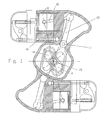
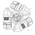
- the balanced rotary engine shows a balanced rotary engine ( Figures 1, 2 and 3) whereas the second embodiment shows a self-powered balanced rotary engine ( Figures 4, 5, 6, 7, 8, 9 and 10).
- the pistons (11) ( Figures 1, 2 and 3) are coupled by means of their connecting rods (12) and the pivoted lever (13), to a gudgeon (14) of the crankshaft (15), which is shifted the same number of degrees ads the cylinders (16), thus obtaining in its linear alternative shifting during the rotation of the assembly (the block with these elements rotates in one direction and the crankshaft in the other) that they remain permanently balanced, either due to the opposite one or as a whole, in the case of an engine with an odd number of cylinders ( Figure 3).
- This arrangement allows coupling ( Figure 2) two pistons (11) to the same gudgeon (14) of the crankshaft (15) provided that the aforementioned conditions are maintained.
- crankshaft (15) and the grooved part of the pivoted lever (13) are located in a chamber in the central part, separated from the outer ones by the rotating shaft (17) of this lever (13), enabling their individual lubrication with the oil accumulated therein, whereas the pistons (11), connecting rods (12) and the outer part of the pivoted lever (13) can be carried out with different means; in the case of a two-stroke operation with oil added to the fuel and in other cycles injected directly in this area, or by enabling controlled passage from the central chamber (by centrifugal force) and subsequently recovering it thereto by means of a pump provided for such purpose.
- the air or mixture is drawn directly from the rear of the cylinder (26), compressed during the return of the piston (21) and subsequently injected into the combustion chamber of said cylinder or of the cylinder (26) adjacent thereto.
- the air or mixture ( Figures 4 and 5) is drawn by the piston (21) during the forwards shifting through the check valve (28) from the rear chamber of the cylinder, compressed during the return of the cylinder, and injected in the combustion chamber through the duct (29) and the valve (210) controlled by a mechanism actuated by the shaft (211) connecting the connecting rod (22) to the pivoted lever (23): this shaft has a bearing (212) coupled thereto in its inner part which in its backwards shifting attacks the profile (213), making it rotate, and which, by means of the cam (214) it has coupled thereto in the outer part of the rotating shaft, acts on the rod (215) moving the rocker (216) and opens this intake valve, scavenging all the gases that are exiting through the nozzle (217) and fills the chamber for a new combustion.
- FIGs 6 and 7 show the same process, but in this case the burning agent or mixture is injected into the chamber of the adjacent cylinder (26), the bearing (212) has been substituted with a blade (221) which acts directly on the valve by means of a profile with a rocker coupled to its shaft.
- the mechanisms for controlling the opening of the intake valve can be substituted by another system, such as those currently used consisting of gears or pulleys actuated directly by the crankshaft.
- Figure 7 shows the sequence of movements of a self-powered balanced rotary engine with two cylinders.
- a first situation ( Figure 7A)
- the cylinder 6' is in a compression and intake phase, the intake being from its rear, and cylinder 6", which belongs to another body, is in the expansion phase.
- cylinder 6' completes the compression and 6" is still in the expansion phase.
- sequence 7C cylinder 6' is reaching the end of its run, the blade actuates the profile opening the intake valve of cylinder 6" and the burning agent or mixture compressed by cylinder 6' enters the intake chamber, and the exhaust nozzle is partially open so as to facilitate scavenging, and cylinder 6" begins the compression phase.
- sequence 7D cylinder 6' completes the expansion phase and the blade releases the profile, the intake valve of cylinder 6" closes when the exhaust nozzle is already closed and continues with its compression phase.
- Figure 8 shows that the piston (21) is provided with a skirt (218) so as to prevent the rear chamber of the cylinder from coming into contact with the exhaust nozzle (217) during the forward run thereof.
- the fuel intake is provided for through the front shaft (219) and said fuel can be injected directly into the combustion chamber for diesel cycles, into the intake duct (29) or into the inlet of the burning agent through the check valve (28).
- This valve (28) can be a rotating valve, a reed valve, a spring valve or a valve controlled by a mechanism similar to those previously described.
- Figure 9 shows a detail of the design and actuation of the mechanism actuating the intake valve for a self-powered balanced rotary engine injecting the burning agent or mixture into the adjacent cylinder.
- the roller (212) has been substituted by the blade (221), integral with the shaft (211) for connecting the connecting rod with the pivoted lever, and acts on profile (213), joined by a shaft to the rocker (216) which opens the intake valve.
- the blade (221) reaches the profile (213) and shifts it upwards, generating the rotation of its shaft and of the rocker (216) which is transmitted to the intake valve, opening it.
Landscapes
- Engineering & Computer Science (AREA)
- Mechanical Engineering (AREA)
- General Engineering & Computer Science (AREA)
- Chemical & Material Sciences (AREA)
- Combustion & Propulsion (AREA)
- Lubrication Of Internal Combustion Engines (AREA)
- Shafts, Cranks, Connecting Bars, And Related Bearings (AREA)
Applications Claiming Priority (4)
| Application Number | Priority Date | Filing Date | Title |
|---|---|---|---|
| ES200401019 | 2004-04-29 | ||
| ES200401419A ES2261007B1 (es) | 2004-06-10 | 2004-06-10 | Motor rotativo equilibrado. |
| ES200401926 | 2004-08-03 | ||
| PCT/ES2005/070047 WO2005106203A1 (es) | 2004-04-29 | 2005-04-21 | Motor rotativo equilibrado |
Publications (1)
| Publication Number | Publication Date |
|---|---|
| EP1748152A1 true EP1748152A1 (de) | 2007-01-31 |
Family
ID=35241734
Family Applications (1)
| Application Number | Title | Priority Date | Filing Date |
|---|---|---|---|
| EP05735159A Withdrawn EP1748152A1 (de) | 2004-04-29 | 2005-04-21 | Gleichgewichtsrotationsmotor |
Country Status (6)
| Country | Link |
|---|---|
| US (1) | US20070227345A1 (de) |
| EP (1) | EP1748152A1 (de) |
| JP (1) | JP2007534886A (de) |
| AU (1) | AU2005238671A1 (de) |
| CA (1) | CA2564683A1 (de) |
| WO (1) | WO2005106203A1 (de) |
Cited By (1)
| Publication number | Priority date | Publication date | Assignee | Title |
|---|---|---|---|---|
| WO2014013110A1 (es) * | 2012-07-16 | 2014-01-23 | Francisco Javier Ruiz Martinez | Motor térmico de pistones rotativo |
Families Citing this family (8)
| Publication number | Priority date | Publication date | Assignee | Title |
|---|---|---|---|---|
| ES2302608B1 (es) * | 2006-03-23 | 2009-05-20 | Francisco J. Ruiz Martinez | Motor rotativo hibrido. |
| JP2010504471A (ja) * | 2006-09-26 | 2010-02-12 | カサン,ラリー | ロータリー内燃エンジン |
| RU2369758C2 (ru) * | 2007-10-11 | 2009-10-10 | Илья Николаевич Шепталов | Поршневой двигатель внутреннего сгорания с храповым валом и челночным механизмом возврата основных поршней в исходное положение (пдвсхвчм) |
| RU2372502C1 (ru) * | 2008-03-14 | 2009-11-10 | Илья Николаевич Шепталов | Поршневой двигатель внутреннего сгорания с двойным храповым валом и челночно-рычажным механизмом возврата поршней в исходное положение (пдвсдхвчрм) |
| GB2477997B (en) | 2010-02-23 | 2015-01-14 | Artemis Intelligent Power Ltd | Fluid working machine and method for operating fluid working machine |
| US9133838B2 (en) | 2010-02-23 | 2015-09-15 | Artemis Intelligent Power Limited | Fluid-working machine and method of operating a fluid-working machine |
| US9003765B1 (en) * | 2011-07-14 | 2015-04-14 | Barry A. Muth | Engine having a rotary combustion chamber |
| KR101965008B1 (ko) * | 2014-02-25 | 2019-08-13 | 임해문 | 자동차용 내연기관으로 회전피스톤에 의한 동력 발생장치 |
Family Cites Families (13)
| Publication number | Priority date | Publication date | Assignee | Title |
|---|---|---|---|---|
| US947226A (en) * | 1908-11-10 | 1910-01-25 | William C Clark | Gas-engine. |
| US1572541A (en) * | 1924-05-01 | 1926-02-09 | James S Lawrence | Rotary engine |
| US1830046A (en) * | 1928-09-28 | 1931-11-03 | White Frank | Internal combustion engine |
| US1918174A (en) * | 1930-07-26 | 1933-07-11 | Frans L Berggren | Rotary gas motor |
| US2886017A (en) * | 1957-12-23 | 1959-05-12 | Basil H Dib | Rotary internal combustion engine |
| JPS5546075A (en) * | 1978-09-29 | 1980-03-31 | Shimooka Tadao | Torque doubling device using lever |
| ES2072175B1 (es) * | 1992-04-24 | 1997-03-01 | Martinez Francisco J Ruiz | Motor de explosion de embolos tangenciales. |
| JPH06280573A (ja) * | 1993-03-26 | 1994-10-04 | Yoshiaki Hidaka | 2サイクルエンジン |
| US6240884B1 (en) * | 1998-09-28 | 2001-06-05 | Lillbacka Jetair Oy | Valveless rotating cylinder internal combustion engine |
| ES1043373Y (es) * | 1999-06-30 | 2000-05-01 | Ribas Antonio Boned | Dispositivo de autocompresion para motor. |
| JP2000136728A (ja) * | 1999-10-17 | 2000-05-16 | Noriaki Yoshida | ロ―タリ―ピストンエンジン |
| AU2003219301A1 (en) * | 2002-03-28 | 2003-10-13 | Shane Engines Limited | A mechanism including a piston-and-cylinder assembly |
| BG65665B1 (bg) * | 2003-09-25 | 2009-05-29 | ЕНЧЕВ Енчо | Безмотовилков двигател с вътрешно горене |
-
2005
- 2005-04-21 EP EP05735159A patent/EP1748152A1/de not_active Withdrawn
- 2005-04-21 JP JP2007510056A patent/JP2007534886A/ja active Pending
- 2005-04-21 AU AU2005238671A patent/AU2005238671A1/en not_active Abandoned
- 2005-04-21 WO PCT/ES2005/070047 patent/WO2005106203A1/es not_active Ceased
- 2005-04-21 CA CA002564683A patent/CA2564683A1/en not_active Abandoned
- 2005-04-21 US US11/568,452 patent/US20070227345A1/en not_active Abandoned
Non-Patent Citations (1)
| Title |
|---|
| See references of WO2005106203A1 * |
Cited By (1)
| Publication number | Priority date | Publication date | Assignee | Title |
|---|---|---|---|---|
| WO2014013110A1 (es) * | 2012-07-16 | 2014-01-23 | Francisco Javier Ruiz Martinez | Motor térmico de pistones rotativo |
Also Published As
| Publication number | Publication date |
|---|---|
| JP2007534886A (ja) | 2007-11-29 |
| US20070227345A1 (en) | 2007-10-04 |
| CA2564683A1 (en) | 2005-11-10 |
| WO2005106203A1 (es) | 2005-11-10 |
| AU2005238671A1 (en) | 2005-11-10 |
Similar Documents
| Publication | Publication Date | Title |
|---|---|---|
| JP3016485B2 (ja) | クランク無し往復運動2サイクル内燃機関 | |
| JP4459625B2 (ja) | 内燃機関 | |
| ITMO990280A1 (it) | Motore termico alternativo dotato di equilibratura e precompressione | |
| KR20040032970A (ko) | 개선된 왕복 내연 기관 | |
| US4884532A (en) | Swinging-piston internal-combustion engine | |
| EP1748152A1 (de) | Gleichgewichtsrotationsmotor | |
| CN100470015C (zh) | 往复式内燃机 | |
| CA2564329A1 (en) | Balanced rotary engine | |
| JPH01237301A (ja) | パワートランスミッション装置 | |
| US5138993A (en) | Rotary wavy motion type engine | |
| WO1988007127A1 (en) | Two-stroke cycle engine and pump having three-stroke cycle effect | |
| US3968777A (en) | Internal combustion engine | |
| JP3089577B2 (ja) | エンジンの過給装置 | |
| CN100593078C (zh) | 平衡旋转发动机 | |
| MX2008015124A (es) | Motor con camara de combustion interna de dos tiempos con dos pistones encontrados por cilindro. | |
| JP2000506245A (ja) | 連続回転エンジン | |
| US3621758A (en) | Reciprocating piston machine | |
| US1301141A (en) | Internal-combustion engine. | |
| RU2144142C1 (ru) | Двигатель внутреннего сгорания с качающимся поршнем | |
| RU2260129C2 (ru) | Двигатель внутреннего сгорания | |
| WO1991006752A1 (en) | Internal combustion engine | |
| RU2078959C1 (ru) | Роторный двигатель внутреннего сгорания "илюша" | |
| RU2224899C2 (ru) | Поршневая машина | |
| JPH09324649A (ja) | クランク室過給式v型エンジン搭載車両 | |
| KR19980013598A (ko) | 복동기관(Double acting engine) |
Legal Events
| Date | Code | Title | Description |
|---|---|---|---|
| PUAI | Public reference made under article 153(3) epc to a published international application that has entered the european phase |
Free format text: ORIGINAL CODE: 0009012 |
|
| 17P | Request for examination filed |
Effective date: 20061121 |
|
| AK | Designated contracting states |
Kind code of ref document: A1 Designated state(s): AT BE BG CH CY CZ DE DK EE ES FI FR GB GR HU IE IS IT LI LT LU MC NL PL PT RO SE SI SK TR |
|
| DAX | Request for extension of the european patent (deleted) | ||
| 17Q | First examination report despatched |
Effective date: 20100331 |
|
| STAA | Information on the status of an ep patent application or granted ep patent |
Free format text: STATUS: THE APPLICATION IS DEEMED TO BE WITHDRAWN |
|
| 18D | Application deemed to be withdrawn |
Effective date: 20100811 |