EP1747939A1 - Rampe für einen Türeinstieg eines Personenbeförderungsfahrzeugs - Google Patents
Rampe für einen Türeinstieg eines Personenbeförderungsfahrzeugs Download PDFInfo
- Publication number
- EP1747939A1 EP1747939A1 EP06008362A EP06008362A EP1747939A1 EP 1747939 A1 EP1747939 A1 EP 1747939A1 EP 06008362 A EP06008362 A EP 06008362A EP 06008362 A EP06008362 A EP 06008362A EP 1747939 A1 EP1747939 A1 EP 1747939A1
- Authority
- EP
- European Patent Office
- Prior art keywords
- ramp
- drive
- platform
- spindle
- ramp platform
- Prior art date
- Legal status (The legal status is an assumption and is not a legal conclusion. Google has not performed a legal analysis and makes no representation as to the accuracy of the status listed.)
- Granted
Links
- 229920002430 Fibre-reinforced plastic Polymers 0.000 claims abstract description 6
- 239000011151 fibre-reinforced plastic Substances 0.000 claims abstract description 6
- 239000004033 plastic Substances 0.000 claims description 8
- 229920003023 plastic Polymers 0.000 claims description 8
- 238000004891 communication Methods 0.000 claims description 3
- 230000005540 biological transmission Effects 0.000 claims description 2
- 239000002184 metal Substances 0.000 abstract 1
- 229910000831 Steel Inorganic materials 0.000 description 2
- XAGFODPZIPBFFR-UHFFFAOYSA-N aluminium Chemical compound [Al] XAGFODPZIPBFFR-UHFFFAOYSA-N 0.000 description 2
- 229910052782 aluminium Inorganic materials 0.000 description 2
- 239000010959 steel Substances 0.000 description 2
- VRAIHTAYLFXSJJ-UHFFFAOYSA-N alumane Chemical class [AlH3].[AlH3] VRAIHTAYLFXSJJ-UHFFFAOYSA-N 0.000 description 1
- 239000004918 carbon fiber reinforced polymer Substances 0.000 description 1
- 238000011109 contamination Methods 0.000 description 1
- 230000001419 dependent effect Effects 0.000 description 1
- 238000002347 injection Methods 0.000 description 1
- 239000007924 injection Substances 0.000 description 1
- 238000001746 injection moulding Methods 0.000 description 1
- 239000000463 material Substances 0.000 description 1
- 238000000034 method Methods 0.000 description 1
- 239000011347 resin Substances 0.000 description 1
- 229920005989 resin Polymers 0.000 description 1
Images


Classifications
-
- B—PERFORMING OPERATIONS; TRANSPORTING
- B60—VEHICLES IN GENERAL
- B60R—VEHICLES, VEHICLE FITTINGS, OR VEHICLE PARTS, NOT OTHERWISE PROVIDED FOR
- B60R3/00—Arrangements of steps or ladders facilitating access to or on the vehicle, e.g. running-boards
- B60R3/02—Retractable steps or ladders, e.g. movable under shock
Definitions
- the present invention relates to a ramp for a door entry of a passenger transport vehicle having a ramp platform arranged in the region of the door entry, which can be moved out of a rest position into a use position by motor.
- Ramps of various kinds are known. These ramps, whether hand ramps or motorized ramps, ultimately serve to facilitate wheelchair users' access to public transport vehicles, and public transport in particular.
- a motor-driven ramp known in which the mobility of the carriage on both sides of the ramp platform so-called ramp carriage are provided, which are displaced by spindles.
- the spindles themselves are driven by a motor.
- Such ramps are arranged directly under the vehicle floor, for example, a bus.
- the drive and associated with the drive drive elements such as motor and spindle, are here separately attached to the vehicle floor or on the body of the vehicle.
- cover the drive means of the ramp from below to prevent contamination.
- the invention is therefore based on the object to provide a ramp for vehicles of passenger transport, and in particular for buses, on the one hand have a low weight, and on the other hand are not designed to be electrically conductive.
- both the ramp platform and the drive are received by a trough-shaped device made of plastic.
- the trough-shaped device made of plastic two advantages are realized. On the one hand, this results in a considerable weight saving compared to a steel tub, and, on the other hand, such a tub is not electrically conductive.
- the ramp platform itself is also made of plastic, no restriction is required in the use of such ramps even in trams or trolleybuses.
- the drive comprises at least one, preferably two spindles arranged parallel to one another, which can be driven by a motor.
- the motor drive for the spindles comprises a motor which is connected to the at least one spindle by a force transmission member, for.
- As a belt drive is in communication.
- the drive of the ramp platform by the at least one spindle via a spindle arranged on the spindle nut, which is in communication with the ramp platform.
- the ramp platform is held in the extended state hinged by the drive.
- this is achieved in that the ramp platform is connected to the drive by a rubber lip, which ensures the vertical pivotability of the ramp platform.
- the trough-shaped device is made of plastic, with a particularly stable trough being able to be formed when using fiber-reinforced plastic.
- the ramp platform is preferably made of plastic, in particular of fiber-reinforced plastic.
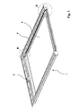
- the trough-shaped device for accommodating the ramp platform 2 with the drive 4 is designated 1.
- the tub-shaped device is characterized in detail by a plastic tub 10 (Figure 8), which serves to accommodate all facilities, so both the drive and the ramp platform itself.
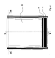
- the top of the tub 10 is covered by the floor of the bus or tram ( Figure 5).
- the tub 10 is made of a fiber-reinforced plastic and is preferably produced by injection molding as a GRP hand laminate in the GRP wet pressing process or by means of GRP vacuum resin injection.
- the drive 3, 4 according to FIG. 1 and FIG. 8 comprises in detail the drive motor 3 with the belt drive 3 a, which is in connection with the spindles 4 a arranged in the guide elements 4.
- the designated 2 ramp platform has the end of the traverse 6, wherein on both sides of the traverse 6 by spindle nuts 7 in conjunction with the spindle 4a is (Figure 3).
- the traverse 6 is connected to the ramp platform 2 by a rubber strip 8, which allows that in the extended state of the ramp platform 2, the ramp platform can fold down, as can be seen for example from Figure 6.
- the tub 10 is covered by the floor of the vehicle, so for example the bus or the tram, as shown for example in Figure 4 but also in Figure 5.
- the bottom of the vehicle is denoted by 20, wherein the bottom of the vehicle in the region of the front end has a flap 21, wherein the flap 21 is connected via a rubber hinge 22 to the ground.
- the ramp platform 2, in the extended and folded state according to FIG. 6, is at a distance from the height of the top side of the platform Bodens 20 up.
- the flap 21 serves to fold onto the ramp when the ramp is folded down according to FIG.
- the mode of operation of the ramp is as follows:
- the belt drive 3a is actuated by the motor drive 3.
- the belt drive 3a is connected to the arranged on both sides of the tub spindle 4a in connection, which is guided in the guide elements 4.
- the flap 21 which is connected by the rubber profile 22 to the bottom 20, with its front end on the ramp platform 2 and bridges so far the height difference between the top of the bottom 20 on the one hand and the top the ramp platform 2 on the other.
Landscapes
- Engineering & Computer Science (AREA)
- Mechanical Engineering (AREA)
- Power-Operated Mechanisms For Wings (AREA)
- Vehicle Step Arrangements And Article Storage (AREA)
- Seal Device For Vehicle (AREA)
- Lock And Its Accessories (AREA)
- Non-Silver Salt Photosensitive Materials And Non-Silver Salt Photography (AREA)
- Photoreceptors In Electrophotography (AREA)
- Transition And Organic Metals Composition Catalysts For Addition Polymerization (AREA)
Abstract
Description
- Die vorliegende Erfindung betrifft eine Rampe für einen Türeinstieg eines Personenbeförderungsfahrzeugs mit einer im Bereich des Türeinstiegs angeordneten Rampenplattform, die aus einer Ruhestellung in eine Gebrauchsstellung motorisch ausfahrbar ist.
- Rampen der unterschiedlichsten Art sind bekannt. Diese Rampen, seien es Handrampen oder motorisch betriebene Rampen, dienen schlussendlich dazu, Rollstuhlfahrern den Zugang zu Fahrzeugen des öffentlichen Personenverkehrs, und hier insbesondere des öffentlichen Personennahverkehrs, zu erleichtern.
- So ist beispielsweise aus der
DE 100 43 561 eine motorisch betriebene Rampe bekannt, bei der zur Verschieblichkeit des Wagens zu beiden Seiten der Rampenplattform sogenannte Rampenwagen vorgesehen sind, die durch Spindeln verschoben werden. Die Spindeln selbst werden hierbei motorisch angetrieben. - Derartige Rampen sind unmittelbar unter dem Fahrzeugboden beispielsweise eines Busses angeordnet. Insbesondere der Antrieb und die mit dem Antrieb in Verbindung stehenden Antriebselemente, wie Motor und Spindel, sind hierbei gesondert am Fahrzeugboden bzw. an der Karosserie des Fahrzeugs befestigt. Zum Schutz der mechanischen Bestandteile der Rampe ist allerdings auch bekannt, die Antriebseinrichtung der Rampe von unten abzudecken, um eine Verschmutzung zu verhindern.
- Gerade bei Bussen besteht in jüngster Zeit das Problem, dass auf Grund einer Vielzahl zusätzlicher Aggregate das Busgewicht erheblich zugenommen hat. Da die Achslast für eine Achse begrenzt ist, sind viele Bushersteller dazu übergegangen, die Achslast auf mehrere Achsen, insbesondere zwei Hinterachsen, zu verteilen. Solche mehrachsigen Busse sind teuer, so dass man bemüht ist, das Gewicht des Busses möglichst niedrig zu halten. Insbesondere bei Straßenbahnen aber auch bei Trolleybussen, also solchen Bussen, die elektrisch angetrieben sind, besteht darüber hinaus das Problem, dass sämtliche Aggregate oder Bauteile nicht so ausgebildet oder auch so eingebaut sind, dass sie nicht elektrisch leitend sind, so dass sich hier der Einsatz von Rampen aus Aluminium oder Stahl verbietet. Ganz abgesehen davon, weisen diese Werkstoffe per se ein nicht unerhebliches Gewicht auf.
- Der Erfindung liegt daher die Aufgabe zu Grunde, eine Rampe für Fahrzeuge des Personenverkehrs, und hier insbesondere für Busse, zu schaffen, die einerseits ein niedriges Eigengewicht aufweisen, und andererseits nicht elektrisch leitend ausgebildet sind.
- Die Aufgabe wird erfindungsgemäß dadurch gelöst, dass sowohl die Rampenplattform als auch der Antrieb von einer wannenförmigen Einrichtung aus Kunststoff aufgenommen werden. Durch die wannenförmige Einrichtung aus Kunststoff werden zweierlei Vorteile verwirklicht. Zum einen wird hierdurch eine erhebliche Gewichtsersparnis gegenüber einer Wanne aus Stahl erreicht, und zum anderen ist eine derartige Wanne nicht elektrisch leitend. Insbesondere wenn die Rampenplattform selbst auch aus Kunststoff hergestellt ist, ist bei einem Einsatz derartiger Rampen selbst in Straßenbahnzügen oder Trolleybussen keine Einschränkung erforderlich.
- Weitere vorteilhafte Merkmale sind den Unteransprüchen zu entnehmen.
- So ist insbesondere vorgesehen, dass der Antrieb mindestens eine, vorzugsweise zwei parallel zueinander angeordnete Spindeln umfasst, die motorisch antreibbar sind. Der motorische Antrieb für die Spindeln umfasst einen Motor, der mit der mindestens einen Spindel durch ein Kraftübertragungsglied, z. B. einem Riementrieb, in Verbindung steht. Der Antrieb der Rampenplattform durch die mindestens eine Spindel erfolgt über eine auf der Spindel angeordnete Spindelmutter, die mit der Rampenplattform in Verbindung steht.
- Nach einem weiteren Merkmal der Erfindung ist die Rampenplattform im ausgefahrenen Zustand abklappbar von dem Antrieb gehalten. Dies wird im einfachsten Fall dadurch erreicht, dass die Rampenplattform mit dem Antrieb durch eine Gummilippe in Verbindung steht, die die vertikale Verschwenkbarkeit der Rampenplattform gewährleistet.
- Wie bereits an anderer Stelle erläutert, ist die wannenförmige Einrichtung aus Kunststoff ausgebildet, wobei eine besonders stabile Wanne sich bei Verwendung von faserverstärktem Kunststoff ausbilden lässt. Gleiches gilt für die Rampenplattform. Auch die Rampenplattform ist vorzugsweise aus Kunststoff, insbesondere aus faserverstärktem Kunststoff, hergestellt.
- Anhand der Zeichnungen wird die Erfindung beispielhaft näher erläutert.
- Figur 1
- zeigt die wannenförmige Einrichtung mit der daran angeordneten Rampenplattform in perspektivischer Darstellung;
- Figur 2
- zeigt die Einzelheit A in vergrößerter Darstellung;
- Figur 3
- zeigt die Einzelheit B in vergrößerter Darstellung;
- Figur 4
- zeigt eine Ansicht auf eine Rampe, wobei die Rampenplattform von oben durch den Boden des Busses oder der Straßenbahn abgedeckt ist;
- Figur 5
- zeigt einen Schnitt gemäß der Linie V - V aus Figur 4;
- Figur 6
- zeigt eine Seitenansicht einer Rampe mit ausgefahrener Rampenplattform;
- Figur 7
- zeigt einen Schnitt gemäß der Linie VII - VII aus Figur 4;
- Figur 8
- zeigt die Rampe mit ihren wesentlichen Bestandteilen in einer Explosionsdarstellung.
- Bei der Darstellung gemäß Figur 1 ist die wannenförmige Einrichtung zur Aufnahme der Rampenplattform 2 mit dem Antrieb 4 mit 1 bezeichnet. Die wannenförmige Einrichtung zeichnet sich im Einzelnen durch eine Kunststoffwanne 10 (Figur 8) aus, die der Aufnahme sämtlicher Einrichtungen, also sowohl des Antriebs als auch der Rampenplattform selbst, dient. Darüber hinaus wird die Oberseite der Wanne 10 durch den Boden des Busses oder der Straßenbahn abgedeckt (Figur 5). Die Wanne 10 besteht aus einem faserverstärkten Kunststoff und ist vorzugsweise im Spritzgießverfahren als GFK-Handlaminat im GFK-Nasspressverfahren oder mittels GFK-Vakuum-Harz-Injektion herstellbar.
- Der Antrieb 3, 4 gemäß Figur 1 und Figur 8 umfasst im Einzelnen den Antriebsmotor 3 mit dem Riementrieb 3a, der in Verbindung mit den in den Führungselementen 4 angeordneten Spindeln 4a steht.
- Die mit 2 bezeichnete Rampenplattform weist endseitig die Traverse 6 auf, wobei zu beiden Seiten die Traverse 6 durch Spindelmuttern 7 in Verbindung mit der Spindel 4a steht (Figur 3). Die Traverse 6 ist mit der Rampenplattform 2 durch eine Gummileiste 8 verbunden, die ermöglicht, dass im ausgefahrenen Zustand der Rampenplattform 2 die Rampenplattform nach unten abklappen kann, wie sich dies beispielsweise aus Figur 6 ergibt. Die Wanne 10 wird abgedeckt durch den Boden des Fahrzeugs, also beispielsweise des Busses oder der Straßenbahn, wie dies beispielsweise in Figur 4 aber auch in Figur 5 dargestellt ist. Der Boden des Fahrzeugs ist hierbei mit 20 bezeichnet, wobei der Boden des Fahrzeugs im Bereich des vorderen Endes eine Klappe 21 besitzt, wobei die Klappe 21 über ein Gummischarnier 22 mit dem Boden verbunden ist. Dies vor folgendem Hintergrund:
- Die Rampenplattform 2 weist im ausgefahrenen und abgeklappten Zustand gemäß Figur 6 einen Abstand zu der Höhe der Oberseite des Bodens 20 auf. Um diesen Abstand zu überbrücken dient die Klappe 21, die bei abgeklappter Rampe gemäß Figur 6 auf die Rampe zu klappt.
- Die Ausbildung und Auflage des Bodens des Busses auf der Wanne 10 ergibt sich insbesondere aus Figur 7. Hier ist erkennbar, dass der Boden 20 seitlich angeordnete Leisten 23 aufweist, mit denen der Boden 20 auf einer entsprechend ausgebildeten Schräge auf der Wanne 10 aufliegt. Der Boden 20 ist hierbei sandwichförmig ausgebildet, um die entsprechenden Lasten aufnehmen zu können, z. B. in Form einer Aluminium-Wellaluminium-Aluminium-Platte oder auch als CFK-Sandwich-Platte.
- Die Funktionsweise der Rampe stellt sich insgesamt wie folgt dar: Durch den motorischen Antrieb 3 wird der Riementrieb 3a betätigt. Der Riementrieb 3a steht mit der zu beiden Seiten der Wanne angeordneten Spindel 4a in Verbindung, die in den Führungselementen 4 geführt ist. Durch die Anordnung von Spindelmuttern 7 zu beiden Seiten der Traverse 6 wird die Rampenplattform 2, die an der Traverse 6 durch eine Gummileiste 8 befestigt ist, ausgeschoben oder eingezogen. Im abgeklappten Zustand der Rampe (Figur 6) liegt die Klappe 21, die durch das Gummiprofil 22 mit dem Boden 20 verbunden ist, mit ihrem stirnseitigen Ende auf der Rampenplattform 2 auf und überbrückt insofern den Höhenunterschied zwischen der Oberseite des Bodens 20 einerseits und der Oberseite der Rampenplattform 2 andererseits.
Claims (7)
- Rampe (1) für einen Türeinstieg eines Personenbeförderungsfahrzeugs mit einer im Bereich des Türeinstiegs angeordneten Rampenplattform, die aus einer Ruhestellung in eine Gebrauchsstellung motorisch ausfahrbar ist,
dadurch gekennzeichnet,
dass sowohl die Rampenplattform (2) als auch der Antrieb (3, 3a, 4, 4a, 6, 8) von der wannenförmigen Einrichtung (1) aus Kunststoff aufgenommen wird. - Rampe nach Anspruch 1,
dadurch gekennzeichnet,
dass der Antrieb (3, 3a, 4, 4a, 6, 8) mindestens eine, vorzugsweise zwei parallel zueinander angeordnete Spindeln (4a) umfasst, die motorisch antreibbar sind. - Rampe nach Anspruch 2,
dadurch gekennzeichnet,
dass zum Antrieb der mindestens einen Spindel (4a) ein Motor (3) vorgesehen ist, der mit der mindestens einen Spindel (4a) durch ein Kraftübertragungsglied (3a), z. B. einem Riementrieb, in Verbindung steht. - Rampe nach einem der voranstehenden Ansprüche ,
dadurch gekennzeichnet,
dass die Rampenplattform (2) durch eine auf der Spindel (4a) angeordnete Spindelmutter (7) mit dem Antrieb verbunden ist. - Rampe nach einem der voranstehenden Ansprüche,
dadurch gekennzeichnet,
dass die Rampenplattform (2) im ausgefahrenen Zustand abklappbar von dem Antrieb gehalten ist. - Rampe nach einem der voranstehenden Ansprüche ,
dadurch gekennzeichnet,
dass die wannenförmige Einrichtung (10) aus faserverstärktem Kunststoff ausgebildet ist. - Rampe nach einem der voranstehenden Ansprüche ,
dadurch gekennzeichnet,
dass die Rampenplattform (2) aus Kunststoff, insbesondere aus faserverstärktem Kunststoff hergestellt ist.
Priority Applications (1)
| Application Number | Priority Date | Filing Date | Title |
|---|---|---|---|
| PL06008362T PL1747939T3 (pl) | 2005-07-29 | 2006-04-22 | Rampa wjazdowa do drzwi pojazdu przeznaczonego do przewozu osób |
Applications Claiming Priority (2)
| Application Number | Priority Date | Filing Date | Title |
|---|---|---|---|
| DE202005011929 | 2005-07-29 | ||
| DE202005012584U DE202005012584U1 (de) | 2005-07-29 | 2005-08-10 | Rampe für einen Türeinstieg eines Personenbeförderungsfahrzeugs |
Publications (2)
| Publication Number | Publication Date |
|---|---|
| EP1747939A1 true EP1747939A1 (de) | 2007-01-31 |
| EP1747939B1 EP1747939B1 (de) | 2008-01-02 |
Family
ID=35483638
Family Applications (1)
| Application Number | Title | Priority Date | Filing Date |
|---|---|---|---|
| EP06008362A Active EP1747939B1 (de) | 2005-07-29 | 2006-04-22 | Rampe für einen Türeinstieg eines Personenbeförderungsfahrzeugs |
Country Status (4)
| Country | Link |
|---|---|
| EP (1) | EP1747939B1 (de) |
| AT (1) | ATE382508T1 (de) |
| DE (2) | DE202005012584U1 (de) |
| PL (1) | PL1747939T3 (de) |
Cited By (2)
| Publication number | Priority date | Publication date | Assignee | Title |
|---|---|---|---|---|
| EP2390142A1 (de) | 2010-05-31 | 2011-11-30 | Hübner Transportation GbmH | Vorrichtung zur ausfahrbaren Aufnahme einer Rampe |
| DE202011106862U1 (de) | 2011-10-15 | 2012-01-19 | Hübner Transportation GmbH | Rampe zum Einbau in Fahrzeuge des Personenverkehrs |
Families Citing this family (7)
| Publication number | Priority date | Publication date | Assignee | Title |
|---|---|---|---|---|
| DE202007013970U1 (de) | 2007-10-05 | 2009-02-19 | Gebr. Bode GmbH & Co. KG Fahrzeugtürsysteme | Trittplattenvorrichtung |
| DE202007013960U1 (de) | 2007-10-05 | 2009-02-19 | Gebr. Bode GmbH & Co. KG Fahrzeugtürsysteme | Trittplattenausfahrvorrichtung |
| DE202008004517U1 (de) | 2008-04-01 | 2009-08-13 | Gebr. Bode Gmbh & Co. Kg | Zustiegshilfe mit verbessertem Spindelantrieb |
| DE202008004592U1 (de) | 2008-04-02 | 2009-08-13 | Gebr. Bode Gmbh & Co. Kg | Türsystem mit Piezosensierung |
| FR2947224B1 (fr) * | 2009-06-25 | 2011-06-03 | Myd L | Dispositif d'aide au franchissement d'une marche pour un vehicule a roues |
| DE202012008578U1 (de) | 2011-11-19 | 2012-11-20 | Hübner Transportation GmbH | Vorrichtung zur ausfahrbaren Aufnahme einer Rampe |
| DE102019004798A1 (de) * | 2019-07-09 | 2021-01-14 | Man Truck & Bus Se | Klapprampe für ein Fahrzeug sowie Fahrzeug mit einer derartigen Klapprampe |
Citations (6)
| Publication number | Priority date | Publication date | Assignee | Title |
|---|---|---|---|---|
| WO1994005878A1 (en) * | 1992-08-27 | 1994-03-17 | Designatech Services Pty. Ltd. | Transportable ramp |
| WO1998006370A1 (en) * | 1996-08-15 | 1998-02-19 | Tieman Industries Pty. Ltd. | A retractable ramp assembly |
| US5775232A (en) * | 1997-02-14 | 1998-07-07 | Vapor Corporation | Bridge plate for a mass transit vehicle |
| DE19818821C2 (de) * | 1998-04-27 | 2000-07-27 | Dieter Gobbers | Hubvorrichtung zum Heben eines Rollstuhls |
| DE10043561A1 (de) | 2000-09-01 | 2002-03-28 | Lohmann Appbau Gmbh | Rampe für einen Türeinstieg |
| DE202004013587U1 (de) * | 2004-08-31 | 2004-11-18 | Hübner GmbH | Rampe für ein Fahrzeug des Personenverkehrs, insbesondere für einen Bus |
-
2005
- 2005-08-10 DE DE202005012584U patent/DE202005012584U1/de not_active Expired - Lifetime
-
2006
- 2006-04-22 PL PL06008362T patent/PL1747939T3/pl unknown
- 2006-04-22 EP EP06008362A patent/EP1747939B1/de active Active
- 2006-04-22 AT AT06008362T patent/ATE382508T1/de not_active IP Right Cessation
- 2006-04-22 DE DE502006000257T patent/DE502006000257D1/de active Active
Patent Citations (6)
| Publication number | Priority date | Publication date | Assignee | Title |
|---|---|---|---|---|
| WO1994005878A1 (en) * | 1992-08-27 | 1994-03-17 | Designatech Services Pty. Ltd. | Transportable ramp |
| WO1998006370A1 (en) * | 1996-08-15 | 1998-02-19 | Tieman Industries Pty. Ltd. | A retractable ramp assembly |
| US5775232A (en) * | 1997-02-14 | 1998-07-07 | Vapor Corporation | Bridge plate for a mass transit vehicle |
| DE19818821C2 (de) * | 1998-04-27 | 2000-07-27 | Dieter Gobbers | Hubvorrichtung zum Heben eines Rollstuhls |
| DE10043561A1 (de) | 2000-09-01 | 2002-03-28 | Lohmann Appbau Gmbh | Rampe für einen Türeinstieg |
| DE202004013587U1 (de) * | 2004-08-31 | 2004-11-18 | Hübner GmbH | Rampe für ein Fahrzeug des Personenverkehrs, insbesondere für einen Bus |
Cited By (2)
| Publication number | Priority date | Publication date | Assignee | Title |
|---|---|---|---|---|
| EP2390142A1 (de) | 2010-05-31 | 2011-11-30 | Hübner Transportation GbmH | Vorrichtung zur ausfahrbaren Aufnahme einer Rampe |
| DE202011106862U1 (de) | 2011-10-15 | 2012-01-19 | Hübner Transportation GmbH | Rampe zum Einbau in Fahrzeuge des Personenverkehrs |
Also Published As
| Publication number | Publication date |
|---|---|
| EP1747939B1 (de) | 2008-01-02 |
| DE502006000257D1 (de) | 2008-02-14 |
| DE202005012584U1 (de) | 2005-12-01 |
| ATE382508T1 (de) | 2008-01-15 |
| PL1747939T3 (pl) | 2008-05-30 |
Similar Documents
| Publication | Publication Date | Title |
|---|---|---|
| EP1747939B1 (de) | Rampe für einen Türeinstieg eines Personenbeförderungsfahrzeugs | |
| DE69810638T2 (de) | Modularer fahrzeugaufbau und transportsystem | |
| EP0247295B1 (de) | Fahrerhaus-Baureihe für Frontlenker-Lastkraftwagen | |
| EP1738733B1 (de) | Rampe für Fahrzeuge des Personenverkehrs, insbesondere für Busse | |
| DE102007044910A1 (de) | Ladeboden für Kraftfahrzeuge | |
| DE3909937C2 (de) | Elektrisch verfahrbare Markise für ein Personenbeförderungsfahrzeug, insbesondere Omnibus | |
| DE10241687B4 (de) | Ladeboden für einen Laderaum eines Kraftfahrzeuges | |
| DE10105165B4 (de) | Fahrzeugdach | |
| EP2044916B2 (de) | Trittplattenvorrichtung | |
| DE102014212988A1 (de) | Fahrzeug mit einer Einstiegsvorrichtung | |
| EP1646551A1 (de) | Fahrerhaus für ein nutzfahrzeug | |
| DE102011012124A1 (de) | Bodengruppe für eine Mehrzahl von Bauvarianten einer Karosserie eines Personenkraftwagens, insbesondere mit Heckantriebsaggregat | |
| EP0029880B1 (de) | Lastkraftwagen | |
| DE102006058105B4 (de) | Cockpitbaugruppe und Kraftfahrzeug | |
| DE102017000799A1 (de) | Verkleidungsanordnung zur Verkleidung eines Karosserieelements eines Fahrzeugs, sowie Fahrzeug mit einer solchen Verkleidungsanordnung | |
| DE4407132A1 (de) | Zweisitziger Kleinwagen | |
| EP3287347B2 (de) | Hilfsantrieb für einen anhänger und anhänger | |
| DE3634559C1 (en) | Instrument panel for vehicles, especially passenger motor cars | |
| DE102017208175B4 (de) | Lastschiene für ein Kraftfahrzeug sowie Laderaum und Kraftfahrzeug mit einer Lastschiene | |
| DE4240290C2 (de) | Zusammenfügbare Kraftfahrzeuge | |
| EP2952421B1 (de) | Hilfsantrieb für einen anhänger und anhänger | |
| DE102007041633B3 (de) | Kraftfahrzeug mit seitlicher Beladeeinrichtung | |
| EP0748720B1 (de) | Grossraum-Schublade zum Einbau in Servicefahrzeuge | |
| EP1258390A1 (de) | Sitzlehneneinrichtung für ein Kraftfahrzeug | |
| DE10052837B4 (de) | Kraftfahrzeug |
Legal Events
| Date | Code | Title | Description |
|---|---|---|---|
| PUAI | Public reference made under article 153(3) epc to a published international application that has entered the european phase |
Free format text: ORIGINAL CODE: 0009012 |
|
| 17P | Request for examination filed |
Effective date: 20061218 |
|
| AK | Designated contracting states |
Kind code of ref document: A1 Designated state(s): AT BE BG CH CY CZ DE DK EE ES FI FR GB GR HU IE IS IT LI LT LU LV MC NL PL PT RO SE SI SK TR |
|
| AX | Request for extension of the european patent |
Extension state: AL BA HR MK YU |
|
| GRAP | Despatch of communication of intention to grant a patent |
Free format text: ORIGINAL CODE: EPIDOSNIGR1 |
|
| AKX | Designation fees paid |
Designated state(s): AT BE BG CH CY CZ DE DK EE ES FI FR GB GR HU IE IS IT LI LT LU LV MC NL PL PT RO SE SI SK TR |
|
| GRAS | Grant fee paid |
Free format text: ORIGINAL CODE: EPIDOSNIGR3 |
|
| GRAA | (expected) grant |
Free format text: ORIGINAL CODE: 0009210 |
|
| AK | Designated contracting states |
Kind code of ref document: B1 Designated state(s): AT BE BG CH CY CZ DE DK EE ES FI FR GB GR HU IE IS IT LI LT LU LV MC NL PL PT RO SE SI SK TR |
|
| REG | Reference to a national code |
Ref country code: GB Ref legal event code: FG4D Free format text: NOT ENGLISH |
|
| REG | Reference to a national code |
Ref country code: IE Ref legal event code: FG4D Free format text: LANGUAGE OF EP DOCUMENT: GERMAN |
|
| GBT | Gb: translation of ep patent filed (gb section 77(6)(a)/1977) |
Effective date: 20080103 |
|
| REG | Reference to a national code |
Ref country code: CH Ref legal event code: EP |
|
| REF | Corresponds to: |
Ref document number: 502006000257 Country of ref document: DE Date of ref document: 20080214 Kind code of ref document: P |
|
| REG | Reference to a national code |
Ref country code: CH Ref legal event code: NV Representative=s name: R. A. EGLI & CO. PATENTANWAELTE |
|
| PG25 | Lapsed in a contracting state [announced via postgrant information from national office to epo] |
Ref country code: SI Free format text: LAPSE BECAUSE OF FAILURE TO SUBMIT A TRANSLATION OF THE DESCRIPTION OR TO PAY THE FEE WITHIN THE PRESCRIBED TIME-LIMIT Effective date: 20080102 |
|
| REG | Reference to a national code |
Ref country code: PL Ref legal event code: T3 |
|
| ET | Fr: translation filed | ||
| PG25 | Lapsed in a contracting state [announced via postgrant information from national office to epo] |
Ref country code: ES Free format text: LAPSE BECAUSE OF FAILURE TO SUBMIT A TRANSLATION OF THE DESCRIPTION OR TO PAY THE FEE WITHIN THE PRESCRIBED TIME-LIMIT Effective date: 20080413 Ref country code: IS Free format text: LAPSE BECAUSE OF FAILURE TO SUBMIT A TRANSLATION OF THE DESCRIPTION OR TO PAY THE FEE WITHIN THE PRESCRIBED TIME-LIMIT Effective date: 20080502 Ref country code: FI Free format text: LAPSE BECAUSE OF FAILURE TO SUBMIT A TRANSLATION OF THE DESCRIPTION OR TO PAY THE FEE WITHIN THE PRESCRIBED TIME-LIMIT Effective date: 20080102 Ref country code: LT Free format text: LAPSE BECAUSE OF FAILURE TO SUBMIT A TRANSLATION OF THE DESCRIPTION OR TO PAY THE FEE WITHIN THE PRESCRIBED TIME-LIMIT Effective date: 20080102 |
|
| PG25 | Lapsed in a contracting state [announced via postgrant information from national office to epo] |
Ref country code: BG Free format text: LAPSE BECAUSE OF FAILURE TO SUBMIT A TRANSLATION OF THE DESCRIPTION OR TO PAY THE FEE WITHIN THE PRESCRIBED TIME-LIMIT Effective date: 20080402 |
|
| PG25 | Lapsed in a contracting state [announced via postgrant information from national office to epo] |
Ref country code: PT Free format text: LAPSE BECAUSE OF FAILURE TO SUBMIT A TRANSLATION OF THE DESCRIPTION OR TO PAY THE FEE WITHIN THE PRESCRIBED TIME-LIMIT Effective date: 20080602 Ref country code: LV Free format text: LAPSE BECAUSE OF FAILURE TO SUBMIT A TRANSLATION OF THE DESCRIPTION OR TO PAY THE FEE WITHIN THE PRESCRIBED TIME-LIMIT Effective date: 20080102 |
|
| REG | Reference to a national code |
Ref country code: IE Ref legal event code: FD4D |
|
| BERE | Be: lapsed |
Owner name: HUBNER TRANSPORTATION GBMH Effective date: 20080430 |
|
| PG25 | Lapsed in a contracting state [announced via postgrant information from national office to epo] |
Ref country code: SE Free format text: LAPSE BECAUSE OF FAILURE TO SUBMIT A TRANSLATION OF THE DESCRIPTION OR TO PAY THE FEE WITHIN THE PRESCRIBED TIME-LIMIT Effective date: 20080402 Ref country code: IE Free format text: LAPSE BECAUSE OF FAILURE TO SUBMIT A TRANSLATION OF THE DESCRIPTION OR TO PAY THE FEE WITHIN THE PRESCRIBED TIME-LIMIT Effective date: 20080102 Ref country code: CZ Free format text: LAPSE BECAUSE OF FAILURE TO SUBMIT A TRANSLATION OF THE DESCRIPTION OR TO PAY THE FEE WITHIN THE PRESCRIBED TIME-LIMIT Effective date: 20080102 Ref country code: DK Free format text: LAPSE BECAUSE OF FAILURE TO SUBMIT A TRANSLATION OF THE DESCRIPTION OR TO PAY THE FEE WITHIN THE PRESCRIBED TIME-LIMIT Effective date: 20080102 Ref country code: SK Free format text: LAPSE BECAUSE OF FAILURE TO SUBMIT A TRANSLATION OF THE DESCRIPTION OR TO PAY THE FEE WITHIN THE PRESCRIBED TIME-LIMIT Effective date: 20080102 |
|
| PLBE | No opposition filed within time limit |
Free format text: ORIGINAL CODE: 0009261 |
|
| STAA | Information on the status of an ep patent application or granted ep patent |
Free format text: STATUS: NO OPPOSITION FILED WITHIN TIME LIMIT |
|
| PG25 | Lapsed in a contracting state [announced via postgrant information from national office to epo] |
Ref country code: RO Free format text: LAPSE BECAUSE OF FAILURE TO SUBMIT A TRANSLATION OF THE DESCRIPTION OR TO PAY THE FEE WITHIN THE PRESCRIBED TIME-LIMIT Effective date: 20080102 Ref country code: MC Free format text: LAPSE BECAUSE OF NON-PAYMENT OF DUE FEES Effective date: 20080430 |
|
| 26N | No opposition filed |
Effective date: 20081003 |
|
| PG25 | Lapsed in a contracting state [announced via postgrant information from national office to epo] |
Ref country code: EE Free format text: LAPSE BECAUSE OF FAILURE TO SUBMIT A TRANSLATION OF THE DESCRIPTION OR TO PAY THE FEE WITHIN THE PRESCRIBED TIME-LIMIT Effective date: 20080102 |
|
| PG25 | Lapsed in a contracting state [announced via postgrant information from national office to epo] |
Ref country code: BE Free format text: LAPSE BECAUSE OF NON-PAYMENT OF DUE FEES Effective date: 20080430 |
|
| PG25 | Lapsed in a contracting state [announced via postgrant information from national office to epo] |
Ref country code: CY Free format text: LAPSE BECAUSE OF FAILURE TO SUBMIT A TRANSLATION OF THE DESCRIPTION OR TO PAY THE FEE WITHIN THE PRESCRIBED TIME-LIMIT Effective date: 20080102 |
|
| PG25 | Lapsed in a contracting state [announced via postgrant information from national office to epo] |
Ref country code: AT Free format text: LAPSE BECAUSE OF NON-PAYMENT OF DUE FEES Effective date: 20080422 |
|
| PG25 | Lapsed in a contracting state [announced via postgrant information from national office to epo] |
Ref country code: HU Free format text: LAPSE BECAUSE OF FAILURE TO SUBMIT A TRANSLATION OF THE DESCRIPTION OR TO PAY THE FEE WITHIN THE PRESCRIBED TIME-LIMIT Effective date: 20080703 Ref country code: LU Free format text: LAPSE BECAUSE OF NON-PAYMENT OF DUE FEES Effective date: 20080422 |
|
| PG25 | Lapsed in a contracting state [announced via postgrant information from national office to epo] |
Ref country code: GR Free format text: LAPSE BECAUSE OF FAILURE TO SUBMIT A TRANSLATION OF THE DESCRIPTION OR TO PAY THE FEE WITHIN THE PRESCRIBED TIME-LIMIT Effective date: 20080403 |
|
| PGFP | Annual fee paid to national office [announced via postgrant information from national office to epo] |
Ref country code: CH Payment date: 20150420 Year of fee payment: 10 |
|
| PGFP | Annual fee paid to national office [announced via postgrant information from national office to epo] |
Ref country code: IT Payment date: 20150427 Year of fee payment: 10 |
|
| REG | Reference to a national code |
Ref country code: FR Ref legal event code: PLFP Year of fee payment: 11 |
|
| REG | Reference to a national code |
Ref country code: CH Ref legal event code: PL |
|
| PG25 | Lapsed in a contracting state [announced via postgrant information from national office to epo] |
Ref country code: LI Free format text: LAPSE BECAUSE OF NON-PAYMENT OF DUE FEES Effective date: 20160430 Ref country code: CH Free format text: LAPSE BECAUSE OF NON-PAYMENT OF DUE FEES Effective date: 20160430 |
|
| PG25 | Lapsed in a contracting state [announced via postgrant information from national office to epo] |
Ref country code: IT Free format text: LAPSE BECAUSE OF NON-PAYMENT OF DUE FEES Effective date: 20160422 |
|
| REG | Reference to a national code |
Ref country code: FR Ref legal event code: PLFP Year of fee payment: 12 |
|
| REG | Reference to a national code |
Ref country code: FR Ref legal event code: PLFP Year of fee payment: 13 |
|
| PGFP | Annual fee paid to national office [announced via postgrant information from national office to epo] |
Ref country code: NL Payment date: 20240422 Year of fee payment: 19 |
|
| PGFP | Annual fee paid to national office [announced via postgrant information from national office to epo] |
Ref country code: GB Payment date: 20240423 Year of fee payment: 19 |
|
| PGFP | Annual fee paid to national office [announced via postgrant information from national office to epo] |
Ref country code: DE Payment date: 20240418 Year of fee payment: 19 |
|
| PGFP | Annual fee paid to national office [announced via postgrant information from national office to epo] |
Ref country code: FR Payment date: 20240419 Year of fee payment: 19 |
|
| PGFP | Annual fee paid to national office [announced via postgrant information from national office to epo] |
Ref country code: PL Payment date: 20240412 Year of fee payment: 19 |
|
| PGFP | Annual fee paid to national office [announced via postgrant information from national office to epo] |
Ref country code: TR Payment date: 20240415 Year of fee payment: 19 |