EP1747855A1 - Verbindung von zwei Bauteilen, Baukasten und Verfahren zur Ausführung der Verbindung - Google Patents
Verbindung von zwei Bauteilen, Baukasten und Verfahren zur Ausführung der Verbindung Download PDFInfo
- Publication number
- EP1747855A1 EP1747855A1 EP05106982A EP05106982A EP1747855A1 EP 1747855 A1 EP1747855 A1 EP 1747855A1 EP 05106982 A EP05106982 A EP 05106982A EP 05106982 A EP05106982 A EP 05106982A EP 1747855 A1 EP1747855 A1 EP 1747855A1
- Authority
- EP
- European Patent Office
- Prior art keywords
- hollow
- piece
- assembly
- space
- sleeve
- Prior art date
- Legal status (The legal status is an assumption and is not a legal conclusion. Google has not performed a legal analysis and makes no representation as to the accuracy of the status listed.)
- Withdrawn
Links
Images


Classifications
-
- B—PERFORMING OPERATIONS; TRANSPORTING
- B25—HAND TOOLS; PORTABLE POWER-DRIVEN TOOLS; MANIPULATORS
- B25G—HANDLES FOR HAND IMPLEMENTS
- B25G3/00—Attaching handles to the implements
- B25G3/02—Socket, tang, or like fixings
- B25G3/12—Locking and securing devices
- B25G3/24—Locking and securing devices comprising clamping or contracting means acting transversely on the handle or socket
Definitions
- the invention relates to an assembly comprising two parts, in particular a part with high mechanical strength and a part with low radial mechanical strength. It is particularly applicable to the manufacture of tools to cut, slice, clamp or pinch, such as shears, secateurs, pincers, pliers, etc.
- the invention also relates to an assembly kit and a method for producing an assembly.
- the sleeve extends over a length at least equal to the length of the part (of the second hollow part) which is housed in the first part.
- the first part consists of a metal or a metal alloy.
- the second hollow part consists of a composite material.
- the composite material consists of a polymer matrix reinforced with carbon fibers, which are advantageously pultruded carbon fibers.
- the clamping means consist of at least one screw.
- the invention relates to an assembly kit, comprising the elements which have just been described, the dimensions and shapes of which are such that they can cooperate with one another to produce an assembly according to the invention. 'invention.
- the relative dimensions, on the one hand, of the space formed by the upper and lower parts of the first part, and, on the other hand, of the second hollow part are such that there is a functional clearance when the second hollow part is introduced into said space.
- the relative dimensions, on the one hand, of the sleeve and, on the other hand, of the hollow of the second hollow part are such that there is a functional clearance when the socket is introduced into said hollow.
- the assembly according to the invention can be used in many applications, among which include the production of tripods for cameras or cameras, the manufacture of lightweight bicycle frames, golf clubs, etc.
- the assembly of the two parts is particularly resistant, which allows it to be used in applications involving the transmission of very important forces. In this respect, we can mention the manufacture of tools.
- the invention therefore also relates to a tool to cut, slice, clamp or pinch, comprising two branches connected to each other by means of a hinge, each branch comprising a cutting portion, a transmission portion and a handling part or handle, this tool having this particular that it further comprises, between the transmission portion and the handling portion, a connecting portion, this connecting portion forming with the handling portion or handle an assembly as described above, in which the connecting part constitutes the first part and the handle the second hollow part, the fixing of the connecting part to the transmission part being carried out in a manner known to those skilled in the art.
- the connecting part is made of aluminum or aluminum alloy, preferably forged and hardened, and the handling part is made of carbon fibers, preferably pultruded.
- the tool is a secateur with two hands.
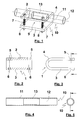
- Figure 1 is shown generally the assembly according to the invention.
- the first part 1 is shown in detail in FIGS. 2 and 3. It distinguishes the upper part 2, the lower part 3 and the hinge part 4.
- the upper 2 and lower 3 parts are substantially in the form of a plate. They comprise at their opposite ends to the hinge part 4 holes 5 and 6 through which screws 7 are fixed by nuts 8.
- the hinge portion 4 which connects them has the shape of a half-cylinder whose thickness corresponds to that of the upper and lower parts 2 and 3.
- the first piece 1 is generally made of metal and it has a certain flexibility. It can be obtained, for example, by folding an iron sheet.
- the holes 6 are threaded, a screw passing through a hole 5 can then be screwed into a hole 6.
- the second hollow part 10 passes right through the first part 1, but according to a variant, only one end of this part 10 is included inside the space 9.
- the second hollow part 10, better visible in FIGS. 4 and 5, is generally in the form of a hollow cylinder. It is advantageously made of a light material, such as a composite material.
- a composite material there may be mentioned materials comprising a fiber-reinforced polymer matrix. Examples of such materials are given from row 3 of column 2 to row 14 of column 3 of the aforementioned European patent application. EP-A-357,490 .
- a polymer matrix reinforced with carbon fibers in particular pultruded carbon fibers, is used.
- the role of this bushing 13 is to locally reinforce the part 10.
- the bushing 13 has a high radial compressive strength, that is to say much greater than that of the part 10. It is generally made of aluminum or alloy aluminum.
- the piece 10 may, despite its relative fragility, transmit very large loads to the first part 1 without bending, twisting, breaking or tearing.
- the screwing of the screws 7 in cooperation with the nuts 8 makes it possible to bring the upper part 2 of the lower part 3 closer and thus to pinch the part of the hollow part 10 being in the space 9, which has the effect of immobilizing the part 10 relative to the part 1.
- the sleeve 13 shown in Figure 1 does not extend over the entire length of the portion 11 which is in the space 9, as this is not necessarily necessary for the assembly to be suitable for the application to which he is destined. However, if it is desired to maximize the mechanical performance of the assembly according to the invention, it should be provided that the sleeve 13 extends axially at least over the entire axial length of the portion 11.
- the assembly according to the invention therefore has the advantage of being able to undergo very high radial and axial mechanical stresses, even when the part 10 does not have good mechanical characteristics.
- the assembly according to the invention also brings the enormous advantage of allowing to use in certain applications materials that could not be used until now.
- materials that could not be used until now.
- the assembly kit according to the invention comprises the first part 1, the second hollow part 10, the sleeve 13, the screws 7 and the nuts 8.
- the screws 7 and the nuts 8 which constitute the clamping means can obviously be replaced by any system exerting a force bringing the upper parts 2 and lower 3 closer to each other, in order to clamp the first part 1.
- the assembly kit according to the invention is intended to give, after assembly, the assembly according to the invention. This amounts to saying that the dimensions and shapes of the pieces are chosen according to each other.
- a functional clearance between the workpiece 1 and the workpiece 10 is provided.
- the functional games have the advantage, in the absence of collages, to allow easy assembly and disassembly of the assembly according to the invention.
- it is possible to disassemble the assembly to replace one or the other of its constituent elements, which would be defective or inappropriate for the intended application, by a element in good condition or more appropriate. This avoids having to change the entire assembly and thus saves money.
- the second elongated piece 10, as well as the socket 13 have in Figures 1, 4 and 5 a circular cross section.
- other cross-sections may be envisaged, in particular polygonal sections, in particular a hexagonal cross-section.
- first part 1 may be very different from that shown in Figures 1 to 3, provided however that it can cooperate with the second part.
- the invention can be implemented in many fields. We will now describe its use in a tool to cut, slice, clamp or pinch, such as shears, secateurs, tongs, pliers, etc.
- Such a tool is a two-handed pruning shears.
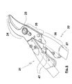
- Such pruner is shown in Figure 6. It has two branches 21 and 22 connected to each other by means of a hinge 23, each branch having a cutting portion 24, a transmission portion 25, a portion link 26 and a handling part or handle 27.
- the cutting and transmission portions 24 form a single piece, generally of hardened steel.
- the materials, the shapes and dimensions of such a part as well as the realization of a joint 23 are well known to manufacturers of tools of this type.
- the connecting part or first part 26 comprises two parts substantially in the form of half-shells 28, 42 facing towards each other, connected by a hinge part. 31 and extending, at their respective end opposite the hinge portion 31, by clamping portions 29,30.
- the clamping portion 29 has a through hole 32 in which a screw 33 is housed which is screwed into a threaded hole 49 of the clamping part 30. Before mounting, there is a gap 39 between the two clamping parts 29 and 30.
- the half-shells 28,42 are open on one side 34 to receive the handle 27, they form between them a substantially cylindrical space 40 and meet on the side 35 which is opposite the side 34. At the side 35, they are extend through a flat end 36 extending substantially parallel to the longitudinal axis of the space 40.
- the flat end 36 has two threaded holes 37 in which are received screws 48 and a smooth hole 53 in which is received a pin 50.
- Such a fastening system is well known to those skilled in the art.
- An elastic abutment 47 is provided in the piece 26, on the side 35, between the flat end 36 and the clamping portions 29,30. This elastic abutment is, in known manner, turned towards the elastic abutment of the other branch 22, so as to dampen shocks when the parts 26 of the branches 21, 22 come into contact with each other during use. of the tool.
- clamping portions 29, 30 each have an end which, as shown in FIG. 8, moves away from the X axis in the form of a lobe 51, 52.
- lobes 51,52 of the branch 22 are intended to abut against their counterparts of the branch 21 (see FIG. 6). By acting as mechanical stops, they limit the bringing together of the two branches 21,22 from one another and thus avoid that the user does not crush the fingers when using the secateur according to the invention .
- the handle 27 has the shape of a hollow cylinder. It is usually made of a material comprising a polymer matrix reinforced with pultruded carbon fibers.
- One end of the handle 27, designated by the number 41, is housed inside the piece 26, that is to say in the space 40 where it enters through the opening on the side 34 of Exhibit 26.
- a sleeve 44 in the form of a hollow cylinder.
- This sleeve 44 is usually a machined alumina piece. It extends in a portion of the recess 43, from the edge 45 of the end 41 of the handle 27, along the axis X of the handle 27. This axis X is substantially parallel to the hinge portion 31.
- sleeve 44 has a length that is greater than the maximum length of the end 41 in the space 40.
- the sleeve 44 has at one end a flange 46 abutting the edge 45 of the end 41, in order to limit its penetration into the recess 43 of the handle 27.
- the flange 46 also abuts against an inner wall of the space 40 when the end 41 is fully inserted into this space.
- the internal diameter of the handle 27, that is to say the diameter of the hollow 43, and the outer diameter of the sleeve 44 are provided so that there is a play during assembly.
- the dimensions of the space 40 of the part 26, the outer diameter of the handle 27 and the outer diameter of the flange 46 of the sleeve 44 are provided so that there is a clearance during assembly.
- the gap 39 between the clamping portions 29, 30 decreases thanks to the flexibility of the piece 26 and the hinge role played by the hinge portion 31.
- the parts 29,30 are brought closer to each other and they pinch the end 41 which is resistant to the pressure force thanks to the reinforcement provided by the sleeve 44.
- Such a fastener advantageously allows to transmit to the piece 26 the forces exerted on the handle 27 without risk of breaking or twisting thereof.
- a shears For assembling a shears according to the invention, it first starts by assembling, by means of the hinge 23, a cutting portion 24 and its transmission portion 25 of a branch 21, with the cutting portion. 24 and its transmission portion 25 of a branch 22.
- One of the cutting portions 24 acts as a blade and the other one against blade.
- each transmission part 25 a connecting part 26, by means of the flat end 36, is fastened with screws 48 and corresponding holes 37.
- a sleeve 44 is inserted into a handle 27, until the flange 46 of the sleeve 44 abuts against the edge 45 of the handle 27.
- This step is carried out twice (because there are two branches in secateurs). It goes without saying that this step can be pre-assembled, that is to say that it can be performed before the aforementioned assembly of a branch with the other.
- each handle 27 + sleeve 44 is inserted into the space 40 of a part 26, until each flange 46 comes into abutment against an inner wall of the space 40. of the corresponding piece 26.
- the free end of each handle 27 usually has a plastic sleeve that is often colored.
- the shears according to the invention can easily be dismounted.
- the screw 33 is unscrewed first. Thanks to the dimensioning of the parts and to the flexibility of the part 26, the gap 39 increases and then a clearance is formed between the piece 26 and the handle 27. last can be removed at hands naked from the room 26. It can then go out, also with bare hands, the sleeve 44 of the end 41.
- the invention allows to have shears with interchangeable handles. Indeed, the user can easily and at any time replace the handles of a pruner by other handles of the same diameter but shorter or longer, a different color, a different material, etc. If he wishes to use handles (and sockets) of different diameter, it can also replace the piece 26 by another piece 26 having a space 40 adapted.
- the information that has just been given concerning the manufacture of a shears can easily be adapted to the realization of a bicycle frame, a golf club, a tripod for camera or camera, etc.
Priority Applications (4)
| Application Number | Priority Date | Filing Date | Title |
|---|---|---|---|
| EP05106982A EP1747855A1 (de) | 2005-07-28 | 2005-07-28 | Verbindung von zwei Bauteilen, Baukasten und Verfahren zur Ausführung der Verbindung |
| US11/476,683 US7654005B2 (en) | 2005-07-28 | 2006-06-29 | Two-piece assembly, assembly kit and method of achieving an assembly |
| JP2006197998A JP2007029091A (ja) | 2005-07-28 | 2006-07-20 | 二つの部品の組立品、組立キット、および、組立品の組立方法 |
| AU2006203244A AU2006203244A1 (en) | 2005-07-28 | 2006-07-28 | Two-piece assembly, assembly kit and method of achieving an assembly |
Applications Claiming Priority (1)
| Application Number | Priority Date | Filing Date | Title |
|---|---|---|---|
| EP05106982A EP1747855A1 (de) | 2005-07-28 | 2005-07-28 | Verbindung von zwei Bauteilen, Baukasten und Verfahren zur Ausführung der Verbindung |
Publications (1)
| Publication Number | Publication Date |
|---|---|
| EP1747855A1 true EP1747855A1 (de) | 2007-01-31 |
Family
ID=35519848
Family Applications (1)
| Application Number | Title | Priority Date | Filing Date |
|---|---|---|---|
| EP05106982A Withdrawn EP1747855A1 (de) | 2005-07-28 | 2005-07-28 | Verbindung von zwei Bauteilen, Baukasten und Verfahren zur Ausführung der Verbindung |
Country Status (4)
| Country | Link |
|---|---|
| US (1) | US7654005B2 (de) |
| EP (1) | EP1747855A1 (de) |
| JP (1) | JP2007029091A (de) |
| AU (1) | AU2006203244A1 (de) |
Cited By (2)
| Publication number | Priority date | Publication date | Assignee | Title |
|---|---|---|---|---|
| WO2013153247A1 (es) * | 2012-04-13 | 2013-10-17 | Altuna Hermanos, S.A. | Tijera de podar de dos manos |
| CN107047083A (zh) * | 2017-03-29 | 2017-08-18 | 华南农业大学 | 一种打顶机器人及其实现方法 |
Families Citing this family (10)
| Publication number | Priority date | Publication date | Assignee | Title |
|---|---|---|---|---|
| US8997359B2 (en) * | 2007-09-07 | 2015-04-07 | Ideal Industries, Inc. | Handheld cable cutter with stabilizing base |
| US8826545B2 (en) * | 2010-01-07 | 2014-09-09 | Robert Bosch Gmbh | Lopping shears |
| US8713804B2 (en) * | 2011-08-24 | 2014-05-06 | Jiin Haur Industrial Co. Ltd. | Gardening scissors |
| US10741285B2 (en) | 2012-08-16 | 2020-08-11 | Ginger.io, Inc. | Method and system for providing automated conversations |
| US10650920B2 (en) | 2012-08-16 | 2020-05-12 | Ginger.io, Inc. | Method and system for improving care determination |
| US20140052465A1 (en) | 2012-08-16 | 2014-02-20 | Ginger.io, Inc. | Method for modeling behavior and health changes |
| US10276260B2 (en) | 2012-08-16 | 2019-04-30 | Ginger.io, Inc. | Method for providing therapy to an individual |
| US10740438B2 (en) | 2012-08-16 | 2020-08-11 | Ginger.io, Inc. | Method and system for characterizing and/or treating poor sleep behavior |
| US10068670B2 (en) | 2012-08-16 | 2018-09-04 | Ginger.io, Inc. | Method for modeling behavior and depression state |
| US11710576B2 (en) | 2021-05-24 | 2023-07-25 | OrangeDot, Inc. | Method and system for computer-aided escalation in a digital health platform |
Citations (13)
| Publication number | Priority date | Publication date | Assignee | Title |
|---|---|---|---|---|
| US564741A (en) * | 1896-07-28 | Velocipede steering-head | ||
| US3380097A (en) | 1967-07-24 | 1968-04-30 | Painter Corp E Z | Extension handle for paint roller |
| US3835535A (en) | 1973-08-20 | 1974-09-17 | Mc Donough Co | Pole pruner with improved cutting head |
| DE7706847U1 (de) * | 1977-03-05 | 1977-06-23 | Braun, Erich, 7400 Tuebingen | Vorrichtung zur befestigung von stielen an werkzeugen |
| FR2588354A1 (fr) | 1985-10-08 | 1987-04-10 | Valeo | Dispositif de raccordement d'un tuyau elastiquement deformable a un tube rigide |
| US4905353A (en) | 1989-02-15 | 1990-03-06 | Gari Francisco A | Hermetic adjustable hose clamp |
| EP0357490A1 (de) | 1988-09-01 | 1990-03-07 | Deville S.A. | Werkzeug zum Schneiden oder Klemmen mit zusammengesetztem Griff |
| US5404616A (en) * | 1993-09-30 | 1995-04-11 | Carmien; Joseph A. | Hand tool with removable handle |
| FR2798087A1 (fr) | 1999-09-03 | 2001-03-09 | Wu Li Tu Lin | Manche d'outil composite |
| FR2814389A1 (fr) | 2000-09-22 | 2002-03-29 | G B Metallurg | Manche pour outils a main |
| US20020096882A1 (en) | 2000-05-23 | 2002-07-25 | Stripe Stanley E. | Tube connector |
| US20030154829A1 (en) | 2001-01-08 | 2003-08-21 | Li-Tu Lin Wu | Hand tool with a composite handle |
| FR2860388A3 (fr) * | 2003-04-08 | 2005-04-08 | Ho Cheng Garden Tools Co Ltd | Structure amelioree de poignee extensible de cisailles a tailler les haies. |
Family Cites Families (8)
| Publication number | Priority date | Publication date | Assignee | Title |
|---|---|---|---|---|
| US3722903A (en) * | 1970-10-26 | 1973-03-27 | J Jones | Adjustable ski pole with split retainer ring |
| US4744690A (en) * | 1987-09-18 | 1988-05-17 | Hsieh Wu H | Stabilizer for telescopic stands |
| US5165686A (en) * | 1990-12-18 | 1992-11-24 | Morgan Edward H | Wooden baseball bat |
| US5454165A (en) * | 1994-01-10 | 1995-10-03 | Harrow Products, Inc. | Hand-held tool with hollow handle |
| US20020128087A1 (en) * | 1997-02-19 | 2002-09-12 | Gordon Tilley | Golf club |
| US6712376B2 (en) * | 2002-05-23 | 2004-03-30 | William J. Eberhardt | Quick release clamp and mounting apparatus for detachably securing an object to a bicycle or other device |
| US6883208B1 (en) * | 2003-03-28 | 2005-04-26 | Yao-Chung Huang | Hedge shear extendable handle enhanced structure |
| US7195377B2 (en) * | 2005-06-09 | 2007-03-27 | Peter Tsai | Worklight support with stand |
-
2005
- 2005-07-28 EP EP05106982A patent/EP1747855A1/de not_active Withdrawn
-
2006
- 2006-06-29 US US11/476,683 patent/US7654005B2/en not_active Expired - Fee Related
- 2006-07-20 JP JP2006197998A patent/JP2007029091A/ja active Pending
- 2006-07-28 AU AU2006203244A patent/AU2006203244A1/en not_active Abandoned
Patent Citations (13)
| Publication number | Priority date | Publication date | Assignee | Title |
|---|---|---|---|---|
| US564741A (en) * | 1896-07-28 | Velocipede steering-head | ||
| US3380097A (en) | 1967-07-24 | 1968-04-30 | Painter Corp E Z | Extension handle for paint roller |
| US3835535A (en) | 1973-08-20 | 1974-09-17 | Mc Donough Co | Pole pruner with improved cutting head |
| DE7706847U1 (de) * | 1977-03-05 | 1977-06-23 | Braun, Erich, 7400 Tuebingen | Vorrichtung zur befestigung von stielen an werkzeugen |
| FR2588354A1 (fr) | 1985-10-08 | 1987-04-10 | Valeo | Dispositif de raccordement d'un tuyau elastiquement deformable a un tube rigide |
| EP0357490A1 (de) | 1988-09-01 | 1990-03-07 | Deville S.A. | Werkzeug zum Schneiden oder Klemmen mit zusammengesetztem Griff |
| US4905353A (en) | 1989-02-15 | 1990-03-06 | Gari Francisco A | Hermetic adjustable hose clamp |
| US5404616A (en) * | 1993-09-30 | 1995-04-11 | Carmien; Joseph A. | Hand tool with removable handle |
| FR2798087A1 (fr) | 1999-09-03 | 2001-03-09 | Wu Li Tu Lin | Manche d'outil composite |
| US20020096882A1 (en) | 2000-05-23 | 2002-07-25 | Stripe Stanley E. | Tube connector |
| FR2814389A1 (fr) | 2000-09-22 | 2002-03-29 | G B Metallurg | Manche pour outils a main |
| US20030154829A1 (en) | 2001-01-08 | 2003-08-21 | Li-Tu Lin Wu | Hand tool with a composite handle |
| FR2860388A3 (fr) * | 2003-04-08 | 2005-04-08 | Ho Cheng Garden Tools Co Ltd | Structure amelioree de poignee extensible de cisailles a tailler les haies. |
Cited By (3)
| Publication number | Priority date | Publication date | Assignee | Title |
|---|---|---|---|---|
| WO2013153247A1 (es) * | 2012-04-13 | 2013-10-17 | Altuna Hermanos, S.A. | Tijera de podar de dos manos |
| ES2429433A1 (es) * | 2012-04-13 | 2013-11-14 | Altuna Hermanos, S.A. | Tijera de podar de dos manos |
| CN107047083A (zh) * | 2017-03-29 | 2017-08-18 | 华南农业大学 | 一种打顶机器人及其实现方法 |
Also Published As
| Publication number | Publication date |
|---|---|
| US7654005B2 (en) | 2010-02-02 |
| US20070022612A1 (en) | 2007-02-01 |
| AU2006203244A1 (en) | 2007-02-15 |
| JP2007029091A (ja) | 2007-02-08 |
Similar Documents
| Publication | Publication Date | Title |
|---|---|---|
| EP1747855A1 (de) | Verbindung von zwei Bauteilen, Baukasten und Verfahren zur Ausführung der Verbindung | |
| EP0390705B1 (de) | Schraubenschlüssel aus Kunststoff mit metallischem Einsatz | |
| FR2761300A1 (fr) | Rayon pour roue de bicyclette | |
| EP2474463B1 (de) | Abnehmbare Vorrichtung zur Kabeldurchführung in einem Zweiradrahmen | |
| FR2491562A1 (fr) | Rivet en deux parties | |
| FR2952853A1 (fr) | Roue composite, notamment pour un cycle, et procede de fabrication d'une telle roue | |
| EP3040167A2 (de) | Halterung für ein schlüsselset | |
| WO1997038414A1 (fr) | Perfectionnements apportes aux ligatures pour bec d'instrument a vent a anche simple | |
| FR2946712A1 (fr) | Bielle pour la construction aeronautique et procede de fabrication d'une telle bielle | |
| EP4137706B1 (de) | Vorrichtung und verfahren zum montieren von rohren | |
| EP2662273B1 (de) | Fahrradsattelrohr mit Einspann-Gabelgelenk | |
| EP2265445B1 (de) | Speichenradspeiche sowie entsprechendes rad und verfahren dafür | |
| FR2753644A1 (fr) | Dispositif d'assemblage d'un mors d'outil | |
| EP1188948B1 (de) | Elastisches Gelenk für einen Stossdämpfer and Stossdämpfer mit einem solchen Gelenk | |
| EP2998208B1 (de) | Vorrichtung zur befestigung einer schutzummantelung einer hand auf dem griff des lenkers eines motorrads | |
| EP1231422A1 (de) | Verfahren zur Herstellung einer unverlierbaren Schraube, Fixierungstellringe für Rohrleitungen und Gebrauch von dem Prozess, die Stellringe herzustellen | |
| FR2781194A1 (fr) | Levier d'actionnement de frein pour une bicyclette | |
| EP1160027B1 (de) | Aufweitzange | |
| FR2689968A1 (fr) | Lame d'escrime. | |
| EP0318401B1 (de) | Eispickel ohne Kopf | |
| EP3795877A1 (de) | Schlauchklemme | |
| FR2831042A1 (fr) | Dispositif et procede de fixation de poignee sur un article culinaire | |
| EP0836994B1 (de) | Zugklemme für Bänder, insbesondere für Spannbänder | |
| EP0724107B1 (de) | Klemmschelle mit schnellverstellungsmöglichkeit. | |
| WO1999037930A1 (fr) | Charniere pour application en micromecanique |
Legal Events
| Date | Code | Title | Description |
|---|---|---|---|
| PUAI | Public reference made under article 153(3) epc to a published international application that has entered the european phase |
Free format text: ORIGINAL CODE: 0009012 |
|
| AK | Designated contracting states |
Kind code of ref document: A1 Designated state(s): AT BE BG CH CY CZ DE DK EE ES FI FR GB GR HU IE IS IT LI LT LU LV MC NL PL PT RO SE SI SK TR |
|
| AX | Request for extension of the european patent |
Extension state: AL BA HR MK YU |
|
| 17P | Request for examination filed |
Effective date: 20070507 |
|
| AKX | Designation fees paid |
Designated state(s): AT BE BG CH CY CZ DE DK EE ES FI FR GB GR HU IE IS IT LI LT LU LV MC NL PL PT RO SE SI SK TR |
|
| 17Q | First examination report despatched |
Effective date: 20081017 |
|
| STAA | Information on the status of an ep patent application or granted ep patent |
Free format text: STATUS: THE APPLICATION IS DEEMED TO BE WITHDRAWN |
|
| 18D | Application deemed to be withdrawn |
Effective date: 20120627 |