EP2265445B1 - Speichenradspeiche sowie entsprechendes rad und verfahren dafür - Google Patents
Speichenradspeiche sowie entsprechendes rad und verfahren dafür Download PDFInfo
- Publication number
- EP2265445B1 EP2265445B1 EP09738337A EP09738337A EP2265445B1 EP 2265445 B1 EP2265445 B1 EP 2265445B1 EP 09738337 A EP09738337 A EP 09738337A EP 09738337 A EP09738337 A EP 09738337A EP 2265445 B1 EP2265445 B1 EP 2265445B1
- Authority
- EP
- European Patent Office
- Prior art keywords
- spoke
- section
- wheel
- equal
- radius
- Prior art date
- Legal status (The legal status is an assumption and is not a legal conclusion. Google has not performed a legal analysis and makes no representation as to the accuracy of the status listed.)
- Not-in-force
Links
Images


Classifications
-
- B—PERFORMING OPERATIONS; TRANSPORTING
- B60—VEHICLES IN GENERAL
- B60B—VEHICLE WHEELS; CASTORS; AXLES FOR WHEELS OR CASTORS; INCREASING WHEEL ADHESION
- B60B21/00—Rims
- B60B21/06—Rims characterised by means for attaching spokes, i.e. spoke seats
- B60B21/062—Rims characterised by means for attaching spokes, i.e. spoke seats for bicycles
-
- B—PERFORMING OPERATIONS; TRANSPORTING
- B60—VEHICLES IN GENERAL
- B60B—VEHICLE WHEELS; CASTORS; AXLES FOR WHEELS OR CASTORS; INCREASING WHEEL ADHESION
- B60B1/00—Spoked wheels; Spokes thereof
- B60B1/003—Spoked wheels; Spokes thereof specially adapted for bicycles
-
- B—PERFORMING OPERATIONS; TRANSPORTING
- B60—VEHICLES IN GENERAL
- B60B—VEHICLE WHEELS; CASTORS; AXLES FOR WHEELS OR CASTORS; INCREASING WHEEL ADHESION
- B60B1/00—Spoked wheels; Spokes thereof
- B60B1/02—Wheels with wire or other tension spokes
- B60B1/0246—Wheels with wire or other tension spokes characterised by cross-section of the spoke, e.g. polygon or elliptic shape
-
- B—PERFORMING OPERATIONS; TRANSPORTING
- B60—VEHICLES IN GENERAL
- B60B—VEHICLE WHEELS; CASTORS; AXLES FOR WHEELS OR CASTORS; INCREASING WHEEL ADHESION
- B60B1/00—Spoked wheels; Spokes thereof
- B60B1/02—Wheels with wire or other tension spokes
- B60B1/0253—Wheels with wire or other tension spokes the spoke being hollow
-
- B—PERFORMING OPERATIONS; TRANSPORTING
- B60—VEHICLES IN GENERAL
- B60B—VEHICLE WHEELS; CASTORS; AXLES FOR WHEELS OR CASTORS; INCREASING WHEEL ADHESION
- B60B1/00—Spoked wheels; Spokes thereof
- B60B1/02—Wheels with wire or other tension spokes
- B60B1/0261—Wheels with wire or other tension spokes characterised by spoke form
-
- B—PERFORMING OPERATIONS; TRANSPORTING
- B60—VEHICLES IN GENERAL
- B60B—VEHICLE WHEELS; CASTORS; AXLES FOR WHEELS OR CASTORS; INCREASING WHEEL ADHESION
- B60B1/00—Spoked wheels; Spokes thereof
- B60B1/02—Wheels with wire or other tension spokes
- B60B1/04—Attaching spokes to rim or hub
- B60B1/041—Attaching spokes to rim or hub of bicycle wheels
-
- B—PERFORMING OPERATIONS; TRANSPORTING
- B60—VEHICLES IN GENERAL
- B60B—VEHICLE WHEELS; CASTORS; AXLES FOR WHEELS OR CASTORS; INCREASING WHEEL ADHESION
- B60B1/00—Spoked wheels; Spokes thereof
- B60B1/02—Wheels with wire or other tension spokes
- B60B1/04—Attaching spokes to rim or hub
- B60B1/043—Attaching spokes to rim
- B60B1/044—Attaching spokes to rim by the use of spoke nipples
- B60B1/045—Attaching spokes to rim by the use of spoke nipples characterised by their specific shape
-
- B—PERFORMING OPERATIONS; TRANSPORTING
- B60—VEHICLES IN GENERAL
- B60B—VEHICLE WHEELS; CASTORS; AXLES FOR WHEELS OR CASTORS; INCREASING WHEEL ADHESION
- B60B21/00—Rims
- B60B21/02—Rims characterised by transverse section
- B60B21/025—Rims characterised by transverse section the transverse section being hollow
-
- B—PERFORMING OPERATIONS; TRANSPORTING
- B60—VEHICLES IN GENERAL
- B60B—VEHICLE WHEELS; CASTORS; AXLES FOR WHEELS OR CASTORS; INCREASING WHEEL ADHESION
- B60B21/00—Rims
- B60B21/06—Rims characterised by means for attaching spokes, i.e. spoke seats
- B60B21/064—Rims characterised by means for attaching spokes, i.e. spoke seats characterised by shape of spoke mounting holes, e.g. elliptical or triangular
-
- B—PERFORMING OPERATIONS; TRANSPORTING
- B60—VEHICLES IN GENERAL
- B60B—VEHICLE WHEELS; CASTORS; AXLES FOR WHEELS OR CASTORS; INCREASING WHEEL ADHESION
- B60B5/00—Wheels, spokes, disc bodies, rims, hubs, wholly or predominantly made of non-metallic material
- B60B5/02—Wheels, spokes, disc bodies, rims, hubs, wholly or predominantly made of non-metallic material made of synthetic material
Definitions
- the present invention relates to a spoke for a spoked wheel, a wheel comprising at least one such spoke and a method of manufacturing such a spoke and a striking tool for implementing this method.
- a bicycle wheel In the field of cycles, a bicycle wheel comprises a peripheral rim and a central hub, these two elements being connected by spokes. All spokes represent 15 to 30% of the weight of a wheel, but they contribute enormously to the rigidity of it. In particular, the lateral stiffness of a wheel is largely determined by the rigidity of the spoke.
- the specific module is the number corresponding to the Young's modulus for a given material divided by the density of the material. For example, for stainless steel whose Young's modulus is 190,000 MPa for a density of 7.8 kg / dm 3, the specific modulus is equal to 24,359 MPa.
- spokes made of composite material are used. These rays are generally composed of fibers embedded in a thermosetting resin matrix of epoxy or polyester type or thermoplastic resin.
- the fibers used may be all high performance fibers, such as, for example, carbon, aramid (eg KEVLAR), polyethylene, PBO (polyphenylenebenzobisoxasole) fibers. These materials have specific modules much higher than metals. On the other hand, these materials are more resistant to fatigue induced by tensioning over very long periods, in particular because the propagation of cracks there is less easily than in metals.
- the document EP 165,590 discloses a spoke having two end pieces attached to each end of a radius body made of composite material.
- the body of the radius is cylindrical with a diameter of approximately 1.5 mm.
- the tip to be connected with the hub is made of a 2.5 mm diameter stainless steel rod and has a bend at its end.
- the tip intended to be connected with the rim comprises an external thread adapted to cooperate with a nut.
- Each end is pierced with a hole of 30 mm depth intended to receive the radius body.
- the connection between the spoke body and the end pieces is made by gluing.
- the bonding perimeter is less than 5 mm, and its length is 30 mm.
- a wheel radius In general, a wheel radius is always stretched and must withstand tensile stress throughout the period and the environments of use. At assembly, when a radius of a length of 300 mm is under tension, its elongation is low; of the order of 0.6 mm. Also, a creep of 0.1 mm causes a voltage loss of the order of 15 to 20%. It is therefore understandable that a ray must be very stable in time and not relax under the permanent constraints to which it is subjected.
- Another disadvantage of the ray described in the document EP 165,590 lies in the difficulty of mounting it on the wheel.
- the person who assembles the spoke to the rim tighten the nut, he must ensure that the torque generated by the friction of the nut on the threaded part of the tip is taken up by an auxiliary tool.
- knowing that a radius made of composite material has a very low resistance to torsion if we do not take this couple, there is a very good chance that the body of the ray breaks or delaminates when power up the beam.
- this recovery must be made by a clamp, which may leave marks on the tip.
- spokes comprising two end pieces attached to each end of a spoke body made of composite material.
- the spoke body and the end pieces are metallic and of circular section.
- the spoke body and a portion of the end pieces have a non-circular section and in this case the end caps are made of plastic. None of the achievements proposed in this document constitutes a sufficiently light and sufficiently rigid radius.
- the object of the present invention is to provide a spoke allowing a wheel equipped with such spokes to be light and rigid.
- Another object of the invention is to provide a spoke enabling a wheel equipped with such spokes to be aerodynamic.
- Another object of the invention is to provide a spoke allowing a wheel equipped with such spokes to be easier to assemble.
- Another object of the invention is to provide a spoke allowing a wheel equipped with such spokes to keep its rigidity characteristics over a very long period.
- Another object of the invention is to provide a radius which is inexpensive to manufacture in large series.
- the radius body has a thickness ( e ) and a length ( I ) such that the ratio between the thickness and the length is less than or equal to 0.5, and preferably less than or equal to 0.33.
- the radius body has a perimeter ( p ) greater than or equal to 10 mm.
- the length L of the end of the body penetrating into the housing of the tip is greater than or equal to 10 mm, and preferably between 12 mm and 15 mm.
- the length ( L ) of the end is less than or equal to the perimeter ( p ) multiplied by 3, and preferably perimeter ( p ) multiplied by 1.5.
- the bonding surface between the end of the spoke body and the tip is greater than or equal to 100 mm 2 .
- the inner wall of the endpiece or at least one of the end pieces is hollowed with streaks for hooking the glue, forming in particular a tapping.
- Said or at least one of said tips is composed of a metal with a density of less than 3 kg / dm 3, this metal possibly being an aluminum alloy or a magnesium alloy.
- a spoked wheel comprising: - a central hub, - a peripheral rim, - spokes connecting the rim to the hub, in which one or (the) spokes is ( are) in accordance with what has just been described above.
- the object of the invention is also achieved by the manufacture of a spoke according to the method comprising the following steps: - forming a blank with a cylindrical end, and - striking the cylindrical end of the blank so as to define the housing of cross-section complementary to that of the radius body.
- the method comprises a first heat treatment step of the blank before the roughing step of the blank and it may possibly comprise a second heat treatment step of the blank after the striking step of the blank. draft.
- the striking tool for implementing the preceding method comprises: a base intended to receive the blank, provided with two abutment surfaces, disposed on either side of a first semi-elliptic rounded hollow profile surface; , the base being further provided with a guide notch for guiding the blank in a striking position, and a punch for striking the cylindrical end of the blank, the punch being provided with complementary abutment surfaces arranged on either side of a second semi-elliptic rounded profile hollow surface, the hollow surfaces defining, during the cooperation of the abutment surfaces, a profile corresponding to that of at least a portion of the end piece.
- the spoke body has an aerodynamic structure whose attachment to the rim and the hub is sufficiently robust to withstand a high voltage and the fatigue cycle due to use in severe conditions by a cyclist.
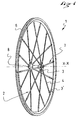
- the figure 1 represents a wheel 1 provided with a plurality of spokes 2.
- Each spoke 2 comprises two end pieces 3, 3 'fixed on a body of radius 4, enabling it to be fixed respectively to a rim 6 and to a hub 8.
- the hub 8 is provided with a central shaft defining a central axis of rotation XX of the wheel 1.
- the figure 2 represents the radius 2 comprising the spoke body 4 and the two ends 3, 3 'attached to the two respective ends of the spoke body 4.
- the spoke body 4 is made of composite material, made for example of carbon fibers or equivalent material , such as KEVLAR, embedded in a thermosetting resin matrix of epoxy or polyester type.
- other high performance fibers such as, for example, aramid fibers, polyethylene or PBO may be used as well as a thermoplastic resin matrix.
- Each of the end pieces 3, 3 ' comprises a fastening section 31, intended to secure the end piece in the rim 6 or the hub 8, and a securing section 32 intended to secure the end piece and the body of the end piece together. radius 4.
- the securing sections 32 of each of the end pieces 3, 3 ' are identical while the attachment sections are different.
- the tip 3, which is to the left of the figure 2a is intended to be screwed into the hub 8.
- Its attachment section 31 consists of an external thread.
- the tip 3 ' which is to the right of the figure 2a is intended to be attached to the rim.
- the figure 2b shows in section how one proceeds to the attachment of the tip 3 'in the rim.
- the fixing portion 31 of the tip 3 ' consists of a threaded hole in which is inserted a pin 10.
- the stud 10 is screwed in force or still screwed glued in such a way that it is integral with the tip 3'.
- a nut 11, screwed on the stud 10 bears on the lower part of a guide element 12, which is inserted between the upper bridge 13 and the lower bridge 14 of the rim.
- the assembly of a spoke according to the invention and the tensioning thereof is carried out as follows. First of all, the spoke is presented with regard to one of the bores of the hub 8, so that the pin 10 enters the guide element 12. Then the end piece 3 is screwed so that the profile wider radius is substantially in the plane of the wheel. This arrangement ensures better aerodynamics at the wheel.
- the desired tensioning of the spoke can be effected in a number of ways.
- the nut 11 is both provided with a flat screwdriver footprint and a square-sided body. We can use a screwdriver or a key.
- the securing section of the end pieces 3 does not have a circular section. It will therefore be easy to immobilize it in rotation with the aid of a key without any pressure being exerted on its surface, as is the case when a clamp immobilizes a cylindrical surface.
- the radius body 4 is elongate in cross section.
- Such a section is defined by a principal dimension, or length l , and by a secondary dimension, or thickness e , such that the thickness e is advantageously substantially less than the length l .
- the ratio between e and l is less than or equal to 0.5, and preferably less than or equal to 0.33.
- e may be equal to 1.8 mm and l equal to 6.4 mm.
- the tip 3 is made of metallic material. It is preferred the use of tips composed of metal having a density of less than 3 kg / dm 3 . By way of example, mention may be made of aluminum or magnesium alloys. A low mass radius 2 is thus obtained.
- the figure 5 illustrates the tip 3, part of which was torn off while the figure 8 represents the tip in its entirety.
- the tip 3 is composed of a fixing portion 31, intended to ensure the attachment of the tip 3 on the rim 6 or the hub 8, and a section 32 for securing the spoke body 4 defining a housing 5 reception of this ray body.
- the securing section 32 has an elongate cross-section allowing the spoke body 4 to be housed inside the mouthpiece 3.
- An end 20 of length L of the spoke body 4, shown in FIG. figure 5 can thus be introduced and then fixed in the end piece 3.
- it is made at the ends of the radius body 4 chamfers 7 thus facilitating the capping of the body of radius 4 in the securing section 32 of the endpiece 3.
- the inner profile of the securing section 32 is similar to that of the radius body 4, shown in FIG. figure 3 , with the presence of a slight peripheral dimensional game.
- the game in question has a value between 0.05 mm and 0.5 mm. It is therefore defined an interspace 9, represented on the figure 5 which can be filled with glue.
- Fixing the end 20 of the radius body 4 can be ensured by gluing.
- it can be used an epoxy glue or an acrylic glue.
- latching streaks can be hollowed out in the section 32, forming for example a tapping.
- the radius body 4 has a perimeter p which is chosen greater than or equal to 10 mm.
- the length L of the end 20 of the radius body 4 is chosen greater than or equal to 10 mm, and preferably between 12 mm and 15 mm.
- a bond area of greater than or equal to 100 mm 2 is obtained, this area being defined by the product of the perimeter p and the length L.
- the perimeter p is equal to 2 x ( l + e ).
- the bonding surface is therefore 2 x ( l + e ) x L.
- the tensile strength of the bonding bond is directly proportional to the bonding perimeter. On the other hand, it is not proportional to the length of the collage.
- a study carried out by the Applicant has shown that during a setting in longitudinal traction glued elements, the maximum stresses are located at both ends of the bonding zone. This study has also shown that these maximum stresses vary only slightly as a function of the length of the bonding zone, but are instead inversely proportional to the external dimension (perimeter) of the bonding zone.
- the invention provides a bonding surface capable of withstanding the tensioning of the radius 2 by limiting the risk of creep relaxation, while having a light radius.
- the invention makes it possible to have a transition between an elongated aerodynamic shape of the radius body 4 and the cylindrical shape of the end piece 3 to ensure the attachment of the spoke 2 to the rim 6 and the hub 8.
- the length ( L ) of the end is less than or equal to the perimeter ( p ) multiplied by 3, and preferably perimeter ( p ) multiplied by 1.5.
- the method of manufacturing the spoke 2 comprises a first step of producing the spoke body 4.
- a pultrusion method is used, well known to those skilled in the art, making it possible to form the spoke section body 4 transverse elongated, represented by way of non-limiting example on Figures 3 and 4 .
- Pultrusion is a very economical method of producing an elongated solid body of constant section.
- the second step consists in producing the end piece 3. It begins by making a cut of a blank 30 shown on the Figures 6 and 7 .
- This blank of cylindrical profile, comprises the fastening section 31, identical to that of the tip 3, and an end 33 intended to form the securing section 32.
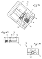
- This end 33 is then struck by means of a striking tool 12, shown on the Figures 11 to 16 .
- a striking tool 12 shown on the Figures 11 to 16 .
- the tip 3 shown on the Figures 8, 9 and 10 , which is composed of the fastening section 31 and the securing section 32. It is possible to provide a heat treatment step before the striking step. The advantage of introducing this step is to lower the mechanical characteristics of the blank 30 to make it easier to hit.
- the embodiment of the tip 3 advantageously meets two requirements.
- the first constraint is to obtain an opening 11 allowing the body of radius 4 to be housed.
- the second imperative consists in being able to obtain a good repeatability of the manufacturing process of the tip 3.
- the tool 12 shown on the Figures 11 to 16 , comprises a base 14, a front wall 15 in which is arranged a guide notch 16 and a punch 18.
- the base 14 is provided with two abutment surfaces 22, disposed on either side of a hollow surface 24 of semi-elliptical rounded profile.
- the guide notch 16 has an elongated profile for sliding the fixing portion 31 of the blank 30.
- the notch 16 comprises at its end a seat 17 semi-circular support of the fastening section 31
- the punch 18 is provided with two abutment surfaces 26 intended to come into contact with the two abutment surfaces 22 of the base 14.
- a surface 28 is hollowed out with a semi-elliptical rounded profile between the abutment surfaces 26. surfaces 24, 28 are defined such that in abutment, a profile corresponding to the external final profile of the securing section 32 is obtained.
- the various parts 14, 18 of the tool 12 can be constituted, by way of example, steel.
- the user places the blank 30 to be struck on the base 14 by means of the guide notch 16.
- the end 33 is placed on the surface 24. It then sets up the punch 18 , so that the surface 28 is in contact with the end 33.
- the blank 30 is then struck so as to crush the securing section 32.
Claims (8)
- Speiche (2) für ein Speichenrad (1), wobei die Speiche eine Felge (6) des Rads mit einer Nabe (8) des Rads verbinden soll, wobei die Speiche Folgendes umfasst:- einen Speichenvollkörper (4) aus einem Verbundmaterial,- mindestens ein Endstück (3) aus einem metallischen Material, das an der Felge oder an der Nabe befestigt werden soll und mit einem Ende (10) des Speichenkörpers verklebt werden soll, dadurch gekennzeichnet, dass der Speichenkörper (4) einen länglichen Querschnitt aufweist und dass das oder mindestens eines der Endstücke (3) eine Aufnahme (5) definiert, deren Innenquerschnitt im Wesentlichen komplementär zu dem des Speichenkörpers ist, um das Ende (10) gegenüber dem Körper zu bedecken, dass der Speichenkörper (4) im Querschnitt einen Umfang (p) aufweist, der größer gleich 10 mm ist, und dass das Material des Endstücks eine Dichte von unter 3 kg/dm3 aufweist.
- Speiche nach Anspruch 1, dadurch gekennzeichnet, dass der Speichenkörper (4) im Querschnitt eine solche Dicke (e) und Länge (l) aufweist, dass das Verhältnis zwischen der Dicke und der Länge kleiner gleich 0,5 und vorzugsweise kleiner gleich 0,33 ist.
- Speiche nach Anspruch 2, dadurch gekennzeichnet, dass eine Länge (L) des Endes (20) des Körpers, das in die Aufnahme des Endstücks (3) eintritt, größer gleich 10 mm ist und vorzugsweise zwischen 12 mm und 15 mm liegt.
- Speiche nach Anspruch 2 oder 3, dadurch gekennzeichnet, dass die Länge (L) des Endes kleiner gleich dem Umfang (p) multipliziert mit 3 und vorzugsweise dem Umfang (p) multipliziert mit 1,5 ist.
- Speiche nach Anspruch 1, dadurch gekennzeichnet, dass eine Klebefläche zwischen dem Ende (20) des Speichenkörpers (4) und dem Endstück (3) größer gleich 100 mm2 ist.
- Speiche nach Anspruch 5, dadurch gekennzeichnet, dass in einer Innenwand des Endstücks (3) oder mindestens eines der Endstücke Rillen zum Anhaften des Klebstoffs ausgebildet sind, die insbesondere ein Innengewinde bilden.
- Speiche nach Anspruch 6, dadurch gekennzeichnet, dass das Metall aus einer Aluminiumlegierung oder einer Magnesiumlegierung besteht.
- Speichenrad, umfassend:- eine mittlere Nabe (8),- eine Umfangsfelge (6),- die Felge mit der Nabe verbindende Speichen (2),dadurch gekennzeichnet, dass mindestens eine der Speichen (2), insbesondere alle Speichen, einem der vorhergehenden Ansprüche entspricht/entsprechen.
Applications Claiming Priority (2)
| Application Number | Priority Date | Filing Date | Title |
|---|---|---|---|
| FR0802075A FR2929882B1 (fr) | 2008-04-15 | 2008-04-15 | Rayon pour une roue a rayons,roue et procede correspondants |
| PCT/FR2009/000435 WO2009133303A2 (fr) | 2008-04-15 | 2009-04-15 | Rayon pour une roue a rayons, roue et procede correspondants |
Publications (2)
| Publication Number | Publication Date |
|---|---|
| EP2265445A2 EP2265445A2 (de) | 2010-12-29 |
| EP2265445B1 true EP2265445B1 (de) | 2012-08-29 |
Family
ID=40054650
Family Applications (1)
| Application Number | Title | Priority Date | Filing Date |
|---|---|---|---|
| EP09738337A Not-in-force EP2265445B1 (de) | 2008-04-15 | 2009-04-15 | Speichenradspeiche sowie entsprechendes rad und verfahren dafür |
Country Status (3)
| Country | Link |
|---|---|
| EP (1) | EP2265445B1 (de) |
| FR (1) | FR2929882B1 (de) |
| WO (1) | WO2009133303A2 (de) |
Cited By (1)
| Publication number | Priority date | Publication date | Assignee | Title |
|---|---|---|---|---|
| TWI566962B (zh) * | 2014-10-23 | 2017-01-21 | Gigantex Composite Technologiesco Ltd | Bicycle low air barrier |
Families Citing this family (2)
| Publication number | Priority date | Publication date | Assignee | Title |
|---|---|---|---|---|
| DE102010022771B4 (de) * | 2010-03-30 | 2023-03-16 | Morgan Nicol | Aerodynamische Abdeckkappe für den Einsatz an Zweirädern |
| FR3057491B1 (fr) * | 2016-10-14 | 2019-06-14 | Mavic Sas | Rayon pour roue de cycle et procede de fabrication d'un tel rayon |
Family Cites Families (10)
| Publication number | Priority date | Publication date | Assignee | Title |
|---|---|---|---|---|
| JPS60174302A (ja) * | 1984-02-20 | 1985-09-07 | Tsukiboshi Seisakusho:Kk | 車両用ニツプル |
| JPS615201U (ja) | 1984-06-18 | 1986-01-13 | 三菱レイヨン株式会社 | 複合スポ−ク |
| FR2586378A1 (fr) * | 1985-08-26 | 1987-02-27 | Viellard Paul Henri | Ensemble composant un rayon tres leger de roue constitue de materiaux composites et d'elements metalliques |
| US5350221A (en) * | 1991-07-11 | 1994-09-27 | Edo Sports Inc. | Fiber reinforced spoke for wheels of bicycles, wheelchairs and the like, and method of making same |
| WO1996041083A1 (en) * | 1995-06-07 | 1996-12-19 | Air Industries Corporation | Deformable locking fastener system and method of use |
| US5779323A (en) * | 1997-04-25 | 1998-07-14 | Giant Manufacturing Co., Ltd. | Spoked wheel with aerodynamic and rigidity imparting spokes |
| FR2816245B1 (fr) * | 2000-11-03 | 2003-02-07 | Mavic Sa | Rayon muni de son organe d'accrochage a une jante ou un moyeu |
| US7357460B2 (en) * | 2003-01-13 | 2008-04-15 | Raphael Schlanger | Connecting system for tensile elements |
| US7784878B2 (en) * | 2004-01-12 | 2010-08-31 | Raphael Schlanger | Connecting system for tensile elements such as spokes |
| FR2900869B1 (fr) * | 2006-05-12 | 2009-03-13 | Salomon Sa | Roue a rayons |
-
2008
- 2008-04-15 FR FR0802075A patent/FR2929882B1/fr active Active
-
2009
- 2009-04-15 WO PCT/FR2009/000435 patent/WO2009133303A2/fr active Application Filing
- 2009-04-15 EP EP09738337A patent/EP2265445B1/de not_active Not-in-force
Cited By (1)
| Publication number | Priority date | Publication date | Assignee | Title |
|---|---|---|---|---|
| TWI566962B (zh) * | 2014-10-23 | 2017-01-21 | Gigantex Composite Technologiesco Ltd | Bicycle low air barrier |
Also Published As
| Publication number | Publication date |
|---|---|
| FR2929882B1 (fr) | 2012-12-14 |
| WO2009133303A2 (fr) | 2009-11-05 |
| FR2929882A1 (fr) | 2009-10-16 |
| WO2009133303A3 (fr) | 2010-05-20 |
| EP2265445A2 (de) | 2010-12-29 |
Similar Documents
| Publication | Publication Date | Title |
|---|---|---|
| EP2504176B1 (de) | Rad aus faserverbundwerkstoff, insbesondere für ein fahrrad, sowie herstellverfahren für ein solches rad | |
| EP2021190B2 (de) | Speichenrad | |
| EP1800897B1 (de) | Rad umfassend eine Felge, eine Nabe und eine Einrichtung zum Verbinden von Felge und Nabe | |
| EP2222538B1 (de) | Träger für ein fahrzeugarmaturenbrett | |
| EP2474463B1 (de) | Abnehmbare Vorrichtung zur Kabeldurchführung in einem Zweiradrahmen | |
| EP1892120B1 (de) | Speiche für ein Speichenrad, Herstellungsverfahren und Rad mit mindestens einer solchen Speiche | |
| EP1747855A1 (de) | Verbindung von zwei Bauteilen, Baukasten und Verfahren zur Ausführung der Verbindung | |
| EP2265445B1 (de) | Speichenradspeiche sowie entsprechendes rad und verfahren dafür | |
| FR2882300A1 (fr) | Dispositif de montage d'un rayon sur une jante ou moyeu de roue | |
| EP1930146A1 (de) | Speiche aus Verbundmaterial für ein Speichenrad | |
| EP3891415B1 (de) | Stossdämpferkörper für stossdämpfer für fahrzeugvorderachse | |
| FR2855099A1 (fr) | Moyeu central d'une roue de velo et roue equipee d'un tel moyeu | |
| EP2937273B1 (de) | Anordnung für fahrrad | |
| EP2662273B1 (de) | Fahrradsattelrohr mit Einspann-Gabelgelenk | |
| FR2915710A1 (fr) | Rayon en metal et matiere composite pour une roue a rayons. | |
| EP0295194B1 (de) | Speichenrad, insbesondere für Fahrräder, Mofas, Motorräder, Kraftfahrzeuge und andere Fahrzeuge | |
| EP1188948B1 (de) | Elastisches Gelenk für einen Stossdämpfer and Stossdämpfer mit einem solchen Gelenk | |
| WO2001096173A1 (fr) | Element support de roue de bicyclette, et moyen amortisseur de vibrations pour un tel element support | |
| FR2762267A1 (fr) | Ame d'un rayon pour roue a rayons, rayon et roue de bicyclette | |
| FR2942744A1 (fr) | Rayon pour une roue de cycle | |
| FR2924380A1 (fr) | Procede de realisation d'une roue en materiaux composites pour cycles ou analogues, et roue ainsi realisee | |
| FR3029851A1 (fr) | Traverse de porte allegee | |
| EP3385152A1 (de) | Fahrradgabel und gabelschaft und gabelkopf, aus dem diese besteht | |
| FR2935927A1 (fr) | Roue a rayon demontable en materiau composite | |
| FR2995558A1 (fr) | Roues allegees a hautes performances |
Legal Events
| Date | Code | Title | Description |
|---|---|---|---|
| PUAI | Public reference made under article 153(3) epc to a published international application that has entered the european phase |
Free format text: ORIGINAL CODE: 0009012 |
|
| 17P | Request for examination filed |
Effective date: 20101006 |
|
| AK | Designated contracting states |
Kind code of ref document: A2 Designated state(s): AT BE BG CH CY CZ DE DK EE ES FI FR GB GR HR HU IE IS IT LI LT LU LV MC MK MT NL NO PL PT RO SE SI SK TR |
|
| AX | Request for extension of the european patent |
Extension state: AL BA RS |
|
| DAX | Request for extension of the european patent (deleted) | ||
| RAP1 | Party data changed (applicant data changed or rights of an application transferred) |
Owner name: MAVIC S.A.S. |
|
| REG | Reference to a national code |
Ref country code: DE Ref legal event code: R079 Ref document number: 602009009329 Country of ref document: DE Free format text: PREVIOUS MAIN CLASS: B60B0001000000 Ipc: B60B0001040000 |
|
| GRAP | Despatch of communication of intention to grant a patent |
Free format text: ORIGINAL CODE: EPIDOSNIGR1 |
|
| RIC1 | Information provided on ipc code assigned before grant |
Ipc: B60B 21/06 20060101ALI20120201BHEP Ipc: B60B 1/00 20060101ALI20120201BHEP Ipc: B60B 1/04 20060101AFI20120201BHEP Ipc: B60B 5/02 20060101ALI20120201BHEP |
|
| GRAS | Grant fee paid |
Free format text: ORIGINAL CODE: EPIDOSNIGR3 |
|
| GRAA | (expected) grant |
Free format text: ORIGINAL CODE: 0009210 |
|
| AK | Designated contracting states |
Kind code of ref document: B1 Designated state(s): AT BE BG CH CY CZ DE DK EE ES FI FR GB GR HR HU IE IS IT LI LT LU LV MC MK MT NL NO PL PT RO SE SI SK TR |
|
| REG | Reference to a national code |
Ref country code: GB Ref legal event code: FG4D Free format text: NOT ENGLISH |
|
| REG | Reference to a national code |
Ref country code: CH Ref legal event code: EP |
|
| REG | Reference to a national code |
Ref country code: AT Ref legal event code: REF Ref document number: 572857 Country of ref document: AT Kind code of ref document: T Effective date: 20120915 |
|
| REG | Reference to a national code |
Ref country code: IE Ref legal event code: FG4D Free format text: LANGUAGE OF EP DOCUMENT: FRENCH |
|
| REG | Reference to a national code |
Ref country code: DE Ref legal event code: R096 Ref document number: 602009009329 Country of ref document: DE Effective date: 20121025 |
|
| REG | Reference to a national code |
Ref country code: AT Ref legal event code: MK05 Ref document number: 572857 Country of ref document: AT Kind code of ref document: T Effective date: 20120829 |
|
| REG | Reference to a national code |
Ref country code: NL Ref legal event code: VDEP Effective date: 20120829 |
|
| REG | Reference to a national code |
Ref country code: LT Ref legal event code: MG4D Effective date: 20120829 |
|
| PG25 | Lapsed in a contracting state [announced via postgrant information from national office to epo] |
Ref country code: HR Free format text: LAPSE BECAUSE OF FAILURE TO SUBMIT A TRANSLATION OF THE DESCRIPTION OR TO PAY THE FEE WITHIN THE PRESCRIBED TIME-LIMIT Effective date: 20120829 Ref country code: FI Free format text: LAPSE BECAUSE OF FAILURE TO SUBMIT A TRANSLATION OF THE DESCRIPTION OR TO PAY THE FEE WITHIN THE PRESCRIBED TIME-LIMIT Effective date: 20120829 Ref country code: LT Free format text: LAPSE BECAUSE OF FAILURE TO SUBMIT A TRANSLATION OF THE DESCRIPTION OR TO PAY THE FEE WITHIN THE PRESCRIBED TIME-LIMIT Effective date: 20120829 Ref country code: NO Free format text: LAPSE BECAUSE OF FAILURE TO SUBMIT A TRANSLATION OF THE DESCRIPTION OR TO PAY THE FEE WITHIN THE PRESCRIBED TIME-LIMIT Effective date: 20121129 Ref country code: AT Free format text: LAPSE BECAUSE OF FAILURE TO SUBMIT A TRANSLATION OF THE DESCRIPTION OR TO PAY THE FEE WITHIN THE PRESCRIBED TIME-LIMIT Effective date: 20120829 Ref country code: IS Free format text: LAPSE BECAUSE OF FAILURE TO SUBMIT A TRANSLATION OF THE DESCRIPTION OR TO PAY THE FEE WITHIN THE PRESCRIBED TIME-LIMIT Effective date: 20121229 |
|
| PG25 | Lapsed in a contracting state [announced via postgrant information from national office to epo] |
Ref country code: SE Free format text: LAPSE BECAUSE OF FAILURE TO SUBMIT A TRANSLATION OF THE DESCRIPTION OR TO PAY THE FEE WITHIN THE PRESCRIBED TIME-LIMIT Effective date: 20120829 Ref country code: GR Free format text: LAPSE BECAUSE OF FAILURE TO SUBMIT A TRANSLATION OF THE DESCRIPTION OR TO PAY THE FEE WITHIN THE PRESCRIBED TIME-LIMIT Effective date: 20121130 Ref country code: LV Free format text: LAPSE BECAUSE OF FAILURE TO SUBMIT A TRANSLATION OF THE DESCRIPTION OR TO PAY THE FEE WITHIN THE PRESCRIBED TIME-LIMIT Effective date: 20120829 Ref country code: PT Free format text: LAPSE BECAUSE OF FAILURE TO SUBMIT A TRANSLATION OF THE DESCRIPTION OR TO PAY THE FEE WITHIN THE PRESCRIBED TIME-LIMIT Effective date: 20121231 Ref country code: SI Free format text: LAPSE BECAUSE OF FAILURE TO SUBMIT A TRANSLATION OF THE DESCRIPTION OR TO PAY THE FEE WITHIN THE PRESCRIBED TIME-LIMIT Effective date: 20120829 |
|
| PG25 | Lapsed in a contracting state [announced via postgrant information from national office to epo] |
Ref country code: CZ Free format text: LAPSE BECAUSE OF FAILURE TO SUBMIT A TRANSLATION OF THE DESCRIPTION OR TO PAY THE FEE WITHIN THE PRESCRIBED TIME-LIMIT Effective date: 20120829 Ref country code: RO Free format text: LAPSE BECAUSE OF FAILURE TO SUBMIT A TRANSLATION OF THE DESCRIPTION OR TO PAY THE FEE WITHIN THE PRESCRIBED TIME-LIMIT Effective date: 20120829 Ref country code: EE Free format text: LAPSE BECAUSE OF FAILURE TO SUBMIT A TRANSLATION OF THE DESCRIPTION OR TO PAY THE FEE WITHIN THE PRESCRIBED TIME-LIMIT Effective date: 20120829 Ref country code: NL Free format text: LAPSE BECAUSE OF FAILURE TO SUBMIT A TRANSLATION OF THE DESCRIPTION OR TO PAY THE FEE WITHIN THE PRESCRIBED TIME-LIMIT Effective date: 20120829 Ref country code: DK Free format text: LAPSE BECAUSE OF FAILURE TO SUBMIT A TRANSLATION OF THE DESCRIPTION OR TO PAY THE FEE WITHIN THE PRESCRIBED TIME-LIMIT Effective date: 20120829 Ref country code: ES Free format text: LAPSE BECAUSE OF FAILURE TO SUBMIT A TRANSLATION OF THE DESCRIPTION OR TO PAY THE FEE WITHIN THE PRESCRIBED TIME-LIMIT Effective date: 20121210 |
|
| PG25 | Lapsed in a contracting state [announced via postgrant information from national office to epo] |
Ref country code: SK Free format text: LAPSE BECAUSE OF FAILURE TO SUBMIT A TRANSLATION OF THE DESCRIPTION OR TO PAY THE FEE WITHIN THE PRESCRIBED TIME-LIMIT Effective date: 20120829 Ref country code: IT Free format text: LAPSE BECAUSE OF FAILURE TO SUBMIT A TRANSLATION OF THE DESCRIPTION OR TO PAY THE FEE WITHIN THE PRESCRIBED TIME-LIMIT Effective date: 20120829 Ref country code: PL Free format text: LAPSE BECAUSE OF FAILURE TO SUBMIT A TRANSLATION OF THE DESCRIPTION OR TO PAY THE FEE WITHIN THE PRESCRIBED TIME-LIMIT Effective date: 20120829 |
|
| PLBE | No opposition filed within time limit |
Free format text: ORIGINAL CODE: 0009261 |
|
| STAA | Information on the status of an ep patent application or granted ep patent |
Free format text: STATUS: NO OPPOSITION FILED WITHIN TIME LIMIT |
|
| PG25 | Lapsed in a contracting state [announced via postgrant information from national office to epo] |
Ref country code: BG Free format text: LAPSE BECAUSE OF FAILURE TO SUBMIT A TRANSLATION OF THE DESCRIPTION OR TO PAY THE FEE WITHIN THE PRESCRIBED TIME-LIMIT Effective date: 20121129 |
|
| PGFP | Annual fee paid to national office [announced via postgrant information from national office to epo] |
Ref country code: CH Payment date: 20130412 Year of fee payment: 5 Ref country code: DE Payment date: 20130508 Year of fee payment: 5 |
|
| 26N | No opposition filed |
Effective date: 20130530 |
|
| REG | Reference to a national code |
Ref country code: DE Ref legal event code: R097 Ref document number: 602009009329 Country of ref document: DE Effective date: 20130530 |
|
| BERE | Be: lapsed |
Owner name: MAVIC S.A.S. Effective date: 20130430 |
|
| PG25 | Lapsed in a contracting state [announced via postgrant information from national office to epo] |
Ref country code: CY Free format text: LAPSE BECAUSE OF FAILURE TO SUBMIT A TRANSLATION OF THE DESCRIPTION OR TO PAY THE FEE WITHIN THE PRESCRIBED TIME-LIMIT Effective date: 20120829 Ref country code: MC Free format text: LAPSE BECAUSE OF FAILURE TO SUBMIT A TRANSLATION OF THE DESCRIPTION OR TO PAY THE FEE WITHIN THE PRESCRIBED TIME-LIMIT Effective date: 20120829 |
|
| GBPC | Gb: european patent ceased through non-payment of renewal fee |
Effective date: 20130415 |
|
| REG | Reference to a national code |
Ref country code: IE Ref legal event code: MM4A |
|
| PG25 | Lapsed in a contracting state [announced via postgrant information from national office to epo] |
Ref country code: GB Free format text: LAPSE BECAUSE OF NON-PAYMENT OF DUE FEES Effective date: 20130415 Ref country code: BE Free format text: LAPSE BECAUSE OF NON-PAYMENT OF DUE FEES Effective date: 20130430 |
|
| PG25 | Lapsed in a contracting state [announced via postgrant information from national office to epo] |
Ref country code: IE Free format text: LAPSE BECAUSE OF NON-PAYMENT OF DUE FEES Effective date: 20130415 |
|
| REG | Reference to a national code |
Ref country code: DE Ref legal event code: R119 Ref document number: 602009009329 Country of ref document: DE |
|
| REG | Reference to a national code |
Ref country code: CH Ref legal event code: PL |
|
| REG | Reference to a national code |
Ref country code: DE Ref legal event code: R119 Ref document number: 602009009329 Country of ref document: DE Effective date: 20141101 |
|
| PG25 | Lapsed in a contracting state [announced via postgrant information from national office to epo] |
Ref country code: DE Free format text: LAPSE BECAUSE OF NON-PAYMENT OF DUE FEES Effective date: 20141101 Ref country code: LI Free format text: LAPSE BECAUSE OF NON-PAYMENT OF DUE FEES Effective date: 20140430 Ref country code: CH Free format text: LAPSE BECAUSE OF NON-PAYMENT OF DUE FEES Effective date: 20140430 |
|
| PG25 | Lapsed in a contracting state [announced via postgrant information from national office to epo] |
Ref country code: MT Free format text: LAPSE BECAUSE OF FAILURE TO SUBMIT A TRANSLATION OF THE DESCRIPTION OR TO PAY THE FEE WITHIN THE PRESCRIBED TIME-LIMIT Effective date: 20120829 |
|
| PG25 | Lapsed in a contracting state [announced via postgrant information from national office to epo] |
Ref country code: TR Free format text: LAPSE BECAUSE OF FAILURE TO SUBMIT A TRANSLATION OF THE DESCRIPTION OR TO PAY THE FEE WITHIN THE PRESCRIBED TIME-LIMIT Effective date: 20120829 |
|
| PG25 | Lapsed in a contracting state [announced via postgrant information from national office to epo] |
Ref country code: MK Free format text: LAPSE BECAUSE OF FAILURE TO SUBMIT A TRANSLATION OF THE DESCRIPTION OR TO PAY THE FEE WITHIN THE PRESCRIBED TIME-LIMIT Effective date: 20120829 Ref country code: HU Free format text: LAPSE BECAUSE OF FAILURE TO SUBMIT A TRANSLATION OF THE DESCRIPTION OR TO PAY THE FEE WITHIN THE PRESCRIBED TIME-LIMIT; INVALID AB INITIO Effective date: 20090415 Ref country code: LU Free format text: LAPSE BECAUSE OF NON-PAYMENT OF DUE FEES Effective date: 20130415 |
|
| REG | Reference to a national code |
Ref country code: FR Ref legal event code: PLFP Year of fee payment: 8 |
|
| REG | Reference to a national code |
Ref country code: FR Ref legal event code: PLFP Year of fee payment: 9 |
|
| REG | Reference to a national code |
Ref country code: FR Ref legal event code: PLFP Year of fee payment: 10 |
|
| PGFP | Annual fee paid to national office [announced via postgrant information from national office to epo] |
Ref country code: FR Payment date: 20180315 Year of fee payment: 10 |
|
| PG25 | Lapsed in a contracting state [announced via postgrant information from national office to epo] |
Ref country code: FR Free format text: LAPSE BECAUSE OF NON-PAYMENT OF DUE FEES Effective date: 20190430 |