EP3891415B1 - Stossdämpferkörper für stossdämpfer für fahrzeugvorderachse - Google Patents
Stossdämpferkörper für stossdämpfer für fahrzeugvorderachse Download PDFInfo
- Publication number
- EP3891415B1 EP3891415B1 EP19831791.9A EP19831791A EP3891415B1 EP 3891415 B1 EP3891415 B1 EP 3891415B1 EP 19831791 A EP19831791 A EP 19831791A EP 3891415 B1 EP3891415 B1 EP 3891415B1
- Authority
- EP
- European Patent Office
- Prior art keywords
- shock absorber
- outer tubular
- absorber body
- composite material
- yoke
- Prior art date
- Legal status (The legal status is an assumption and is not a legal conclusion. Google has not performed a legal analysis and makes no representation as to the accuracy of the status listed.)
- Active
Links
- 230000035939 shock Effects 0.000 title claims description 84
- 239000006096 absorbing agent Substances 0.000 title claims description 82
- 239000002131 composite material Substances 0.000 claims description 77
- 229910052751 metal Inorganic materials 0.000 claims description 33
- 239000002184 metal Substances 0.000 claims description 33
- 239000007769 metal material Substances 0.000 claims description 27
- 239000000725 suspension Substances 0.000 claims description 12
- 238000000465 moulding Methods 0.000 claims description 4
- 101150038956 cup-4 gene Proteins 0.000 description 23
- 238000004519 manufacturing process Methods 0.000 description 16
- 208000031968 Cadaver Diseases 0.000 description 11
- 244000245420 ail Species 0.000 description 9
- 229910000831 Steel Inorganic materials 0.000 description 5
- 229910052782 aluminium Inorganic materials 0.000 description 5
- XAGFODPZIPBFFR-UHFFFAOYSA-N aluminium Chemical compound [Al] XAGFODPZIPBFFR-UHFFFAOYSA-N 0.000 description 5
- 239000010959 steel Substances 0.000 description 5
- 241001080024 Telles Species 0.000 description 2
- 239000011159 matrix material Substances 0.000 description 2
- 238000000034 method Methods 0.000 description 2
- 238000003466 welding Methods 0.000 description 2
- 229920000049 Carbon (fiber) Polymers 0.000 description 1
- 239000004593 Epoxy Substances 0.000 description 1
- 241000208202 Linaceae Species 0.000 description 1
- 235000004431 Linum usitatissimum Nutrition 0.000 description 1
- 238000005452 bending Methods 0.000 description 1
- 239000004917 carbon fiber Substances 0.000 description 1
- 238000005520 cutting process Methods 0.000 description 1
- 230000001627 detrimental effect Effects 0.000 description 1
- 230000001747 exhibiting effect Effects 0.000 description 1
- 239000011521 glass Substances 0.000 description 1
- 239000000463 material Substances 0.000 description 1
- 239000012764 mineral filler Substances 0.000 description 1
- 229920000728 polyester Polymers 0.000 description 1
- 230000002787 reinforcement Effects 0.000 description 1
- 238000009987 spinning Methods 0.000 description 1
- 229920001169 thermoplastic Polymers 0.000 description 1
- 239000004416 thermosoftening plastic Substances 0.000 description 1
- 229920001567 vinyl ester resin Polymers 0.000 description 1
Images


Classifications
-
- F—MECHANICAL ENGINEERING; LIGHTING; HEATING; WEAPONS; BLASTING
- F16—ENGINEERING ELEMENTS AND UNITS; GENERAL MEASURES FOR PRODUCING AND MAINTAINING EFFECTIVE FUNCTIONING OF MACHINES OR INSTALLATIONS; THERMAL INSULATION IN GENERAL
- F16F—SPRINGS; SHOCK-ABSORBERS; MEANS FOR DAMPING VIBRATION
- F16F9/00—Springs, vibration-dampers, shock-absorbers, or similarly-constructed movement-dampers using a fluid or the equivalent as damping medium
- F16F9/32—Details
- F16F9/54—Arrangements for attachment
-
- B—PERFORMING OPERATIONS; TRANSPORTING
- B60—VEHICLES IN GENERAL
- B60G—VEHICLE SUSPENSION ARRANGEMENTS
- B60G13/00—Resilient suspensions characterised by arrangement, location or type of vibration dampers
- B60G13/001—Arrangements for attachment of dampers
- B60G13/005—Arrangements for attachment of dampers characterised by the mounting on the axle or suspension arm of the damper unit
-
- B—PERFORMING OPERATIONS; TRANSPORTING
- B60—VEHICLES IN GENERAL
- B60G—VEHICLE SUSPENSION ARRANGEMENTS
- B60G2204/00—Indexing codes related to suspensions per se or to auxiliary parts
- B60G2204/40—Auxiliary suspension parts; Adjustment of suspensions
- B60G2204/43—Fittings, brackets or knuckles
- B60G2204/4304—Bracket for lower cylinder mount of McPherson strut
-
- B—PERFORMING OPERATIONS; TRANSPORTING
- B60—VEHICLES IN GENERAL
- B60G—VEHICLE SUSPENSION ARRANGEMENTS
- B60G2206/00—Indexing codes related to the manufacturing of suspensions: constructional features, the materials used, procedures or tools
- B60G2206/01—Constructional features of suspension elements, e.g. arms, dampers, springs
- B60G2206/70—Materials used in suspensions
- B60G2206/71—Light weight materials
- B60G2206/7101—Fiber-reinforced plastics [FRP]
-
- F—MECHANICAL ENGINEERING; LIGHTING; HEATING; WEAPONS; BLASTING
- F16—ENGINEERING ELEMENTS AND UNITS; GENERAL MEASURES FOR PRODUCING AND MAINTAINING EFFECTIVE FUNCTIONING OF MACHINES OR INSTALLATIONS; THERMAL INSULATION IN GENERAL
- F16F—SPRINGS; SHOCK-ABSORBERS; MEANS FOR DAMPING VIBRATION
- F16F2224/00—Materials; Material properties
- F16F2224/02—Materials; Material properties solids
- F16F2224/0241—Fibre-reinforced plastics [FRP]
Definitions
- the present invention relates to a shock absorber body for a shock absorber for the front axle of a vehicle, and in particular of a motor vehicle, as well as to a shock absorber for the front axle of a vehicle comprising such a shock absorber body.
- the field of the invention is that of shock absorbers for motor vehicles, used to ensure the suspension of the front axle of the vehicle.
- vehicle shock absorbers and in particular those provided to ensure the suspension of the front axle of the vehicle, comprise a shock absorber body coupled, at a first end, to a pivot of one of the wheels of 'a front axle of the vehicle, and a piston fixed on a piston rod, the piston sliding inside said shock absorber body.
- shock absorber bodies generally comprise, in an upper part, a cup serving as a bearing surface for the lower coils of a suspension spring, inside which the rod receiving the piston extends.
- shock absorber bodies are conventionally made in the form of a single piece of metal, for example steel.
- shock absorber bodies have a significant weight, which is detrimental to the objectives of reducing the consumption of vehicles, and therefore of reducing the pollution generated by the vehicles.
- Certain functional parts requiring to have a particularly high resistance, such as for example the wings can have metal reinforcements positioned outside the overmoulded outer part.
- such a shock absorber body made entirely of composite material, as far as the external part is concerned, even if it has a resistance equivalent to that of a shock absorber body made entirely of metallic material with a reduced weight, nevertheless has a high cost price, in particular in that the composite materials making it possible to obtain the desired mechanical strength are more expensive than the metallic materials used initially for the production of these shock absorber bodies.
- the object of the present invention is therefore to provide a shock absorber body, and in particular a strut, for a train shock absorber front of a vehicle of simple design, with optimum mechanical strength and low weight and having a lower cost price.
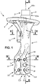
- the outer tubular part 3 made of composite material can extend by covering the tubular section T2 of the inner part 2, from its upper end E3s and to its lower end E3i which extends at the level of the lower end E2i of the tubular section the internal part 2.
- Said outer tubular part 3 comprises a yoke 31, at its lower end E3i, configured so as to be secured to a wheel pivot of the front axle of the vehicle, comprising two wings 33 which extend in a direction substantially perpendicular to the axis A3 of the outer tubular part 3.
- a cup 4 defining a bearing surface for a suspension spring is positioned on said outer tubular part 3, close to the upper end E3s.
- the quantity of composite material necessary for the production of the outer tubular part 3 is reduced, in that the presence of a metal cup 4 replaces that a cup made of composite material, as in the shock absorber bodies of the state of the art, and in particular in that described in the document WO 2014/128131 A1 , with a mechanical resistance at least equivalent, if not superior.
- said stiffening portion 22 made of metallic material, positioned inside the yoke 31, makes it possible to reduce the quantity of composite material used for the production of the yoke 31, and to guarantee said yoke 31 a resistance mechanical at least equivalent, if not superior to that of a shock absorber body with a tubular part made of composite material and devoid of such a stiffening portion at the yoke.
- ribs are generally provided in order to reinforce said outer tubular part at the level of said yoke, as described for example in the document WO 2014/128131 .
- stiffening portion 21 advantageously makes it possible to eliminate these ribs and therefore to reduce the quantity of composite material necessary for the production of the outer tubular part 3 at the level of the said yoke 31.
- the part made of composite material of the yoke 31 may have one or more cavities 35 making it possible to further reduce the use of composite material.
- three cavities 35 can be clearly distinguished in the right wing 33 of the yoke 31 which each extend partially along the thickness E33 of the wings 33 of the yoke 31.
- One of these cavities is visible in the cross-sectional view of the figure 5 .
- the cavity or cavities 35 may extend partially along the thickness E33 of the flanges 33 of the yoke 31 and preferably without uncovering the metallic stiffening portion 22 .
- the weight of the shock absorber body 1 remains substantially identical to that of the shock absorbers of the state of the art comprising an outer tubular portion made entirely of composite material.
- the metallic material used for making the cup 4 or the stiffening portion 21 can thus be, for example, aluminum, or even steel, in particular with high elastic limit (HLE) or high resistance (HR) .
- the composite material used for the outer tubular portion 3 may for example comprise a vinyl ester, polyester or epoxy matrix, or even be a thermoplastic matrix, and glass, flax or even carbon fibers, as well as one or more mineral fillers, depending on the mechanical properties desired for the shock absorber body 1 according to the invention, and in particular for its outer tubular part 3.
- the cost price can be significantly reduced, in that metallic materials are less expensive than composite materials with equivalent or even superior mechanical performance.
- said cup 4 is made of metallic material.
- said metal cup 4 can be fixed on said outer tubular part 3 by being inserted around said outer tubular part 3.
- the cup 4 may comprise for this purpose a central opening 41, configured so as to receive the outer tubular part 3.
- said central opening 41 can be of substantially circular shape, configured so that said cup 4 is held from said outer tubular part 3 by friction.
- additional fixing means such as for example rivets or fixing screws, can be provided in order to ensure the fixing of the cup 4 to the outer tubular part 3.
- the edge of the tubular section T2 at its upper end E2s can be folded towards the inside of said tubular section, in particular in order to constitute a stop in translation for the elements located inside said tubular section T2 , or to close said section tubular T2 of the inner part 2 at its upper end E2s, so as to constitute a sealed closed volume.
- said internal part 2 comprises a stiffening portion 22, made of metallic material, configured so as to be entirely covered by the composite material of said external tubular part 3, at the yoke 31.
- said stiffening portion 22 may be a removable part with respect to the tubular part 2, and fixed to the tubular section T2 of said internal part 2 by welding, or even by means of fixing means, such as rivets .
- said stiffening portion 22 can be made in one piece with the tubular section T2, said internal part 2.
- the cup 4 is made of a metal sheet with a thickness E4 of between 0.5 mm and 3 mm, preferably between 1 and 2 mm. It will be noted that such a thickness E4 of between 1 mm and 2 mm is less than the thickness of the metal cups used when the shock absorber body is, according to the well-known state of the art, made essentially of metallic material.
- the cup 4 of the shock absorber body 1 has a lower thickness E4 than the cup of a shock absorber body whose outer tubular part is made entirely of composite material and provided in one piece on said outer tubular part of the shock absorber body, which makes it possible to reduce the weight of said cup 4, and to reduce its cost price.
- said cup 4 can be obtained by molding, or by stamping operations, with in particular cutouts and bends.
- Said cup 4 may comprise an upper wall 42, with a seat 44, preferably of circular shape, for example in the form of a circular groove 44 configured so as to receive in support the last lower turn of a shock absorber spring , as well as a bottom wall 43.
- said stiffening portion 22 is made in the form of a removable metal sheet, with a fixing portion 23 configured so as to enclose the tubular section T2 of said internal part 2 and a functional portion 24 configured so as to be completely covered by the composite material of the yoke 31 of the outer tubular part 3.
- said fixing portion 23 may be of substantially cylindrical shape, so as to be able to match the shape of the internal part 2.
- the thickness E22 of the sheet constituting said stiffening portion 22 can be between 0.5 mm and 3 mm, preferably between 1 and 2 mm.
- Such a sheet can be obtained by various stamping operations, such as for example cutting and bending.
- one, or even two, studs 25 are made projecting from said internal part 2, close to said lower end E2i, configured so as to be covered by the outer tubular portion 3.
- These studs 25 projecting outwards from the internal part 2 make it possible to ensure that the internal part 2 is covered by the composite material of the external tubular part during the molding of the external tubular part 3 on the internal part 2, and with a thickness E3 equal to at least the length L25 of the studs.
- Such studs 25 advantageously serve as a control to ensure the quality of manufacture of the shock absorber body 1 according to the invention.
- the studs 25 can be dimensioned such that their covering by the composite material of the outer tubular portion 3 corresponds to obtaining the desired thickness E3 of the outer tubular portion 3, in particular during the process for producing the body shock absorber 1 according to the invention, in which the outer tubular part 3 is molded over the inner part 2.
- the studs 25 can be configured so as to be completely covered by the composite material of the outer tubular portion 3, or alternatively, and as visible in the embodiment of the picture 3 , the distal end E25 of the studs 25 can come flush with the outer face F3 of the outer tubular portion 3.
- said studs 25 can be provided on the sheet metal forming said stiffening portion 22.
- studs 25 could be provided directly on internal portion 2, at said stiffening portion 22, or elsewhere on said internal portion 2.
- said outer tubular part 3 comprises, near the upper end E3s, a fixing lug 32, configured so as to be secured to an anti-roll bar of the front axle of the vehicle, said fixing lug 32 comprising an insert 5 made of metallic material, completely covered by the composite material of said fixing lug 32.
- the quantity of composite material necessary for the production of a shock absorber body 1 can be reduced, in that, as visible in the embodiment of the figure 5 , the metal insert 5 makes it possible to obtain satisfactory mechanical strength for said fixing lug 32, with a lesser quantity of composite material compared to the shock absorber bodies of the state of the art, the outer tubular part of which, and in particular the fixing lug configured so as to be secured to an anti-roll bar of the front axle of the vehicle, is made entirely of composite material.
- This arrangement therefore participates directly in solving the technical problem solved by the present invention, namely reducing the cost price of a shock absorber body for an equivalent weight, by making it possible to minimize the quantity of composite material necessary for its manufacture.
- the metal insert 5 can be produced in the form of a part independent of the internal part 2, for example in the form of a sheet cut and bent according to the desired configuration, the sheet having a thickness E5 of between 0, 5 mm and 3 mm, preferably between 1 mm and 2 mm.
- said metal insert 5 could also be fixed to said internal part 2, or even made in one piece therewith.
- Said metal insert 5 can also be made, for example, of aluminum, or else of steel, in particular of the HLE or HR type.
- each of said flanges 33 of the yoke 31 comprises two parallel flat faces F33, two through holes 34, of substantially cylindrical shape, extending between the two parallel flat faces F33 being provided in each of the flanges 33, a metal ring 6, of substantially cylindrical shape, being positioned and held by force inside each of the through holes 34, so that each of the longitudinal ends E6 of said metal ring 6 is recessed inside each wings 33, between the two flat faces F33.
- the length L6 of the metal rings 6 may thus be slightly less than the thickness E33 of the flanges 33 of the yoke 31.
- the metal rings 6 advantageously make it possible to mechanically reinforce the yoke 31 at the level of the through holes 34, which are configured to receive fixing screws of the wheel pivot, and are therefore highly stressed, and in particular in torsion with a high torque.
- stiffening ribs 7 are made on said outer tubular part 3, close to the upper end E3s, said stiffening ribs 7 being configured so as to receive a lower face 43 of said cup 4 .
- the stiffening ribs 7 also make it possible to ensure the stopping in translation of the cup 4 on the external tubular part 3, and therefore the positioning of the cup 4 on the external tubular part 3, and can optionally, in addition, facilitate the attachment of the cup 4 to the outer tubular part 3, possibly receiving means for fixing the cup 4 to the outer tubular part 3.
- said stiffening ribs 7 are made in one piece with the outer tubular part 3 made of composite material.
- a plurality of stiffening ribs 7, for example between three and five stiffening ribs 7 can be provided, distributed circularly around the axis A3 of the outer tubular part 3, in order to collect and best distribute the forces received by said cup 4, and in particular those oriented along the axis A3 of the outer tubular part 3.
- a lower end portion 26 of the tubular section T2 of the internal part 2 at the level of the lower end E2i, extending from said lower end E2i has a diameter D26 reduced compared to the diameter D2 of the rest of the tubular section T2, a plug 27, of outer diameter D27 strictly greater than the diameter D26 of the lower end portion 26 of the tubular section T2, being fixed at the level of said lower end E2i, so as to form a circular cavity 28, at the level of the lower end E2i of the tubular section T2, filled with the composite material of the outer tubular part 3.
- the composite material of the outer tubular part 3 can be housed in said circular cavity 28, during the overmolding of the outer tubular part 3 on the inner part 2 during the production of the shock absorber body 1 according to the invention, which will ensure the immobilization in translation of the outer tubular part 3 relative to the inner part 2 along the axis A3 of the outer tubular part 3.
- shock absorber body 1 is thus simplified, and in particular compared to the shock absorber bodies of the state of the art, in which the lower end of the tubular section of the internal part is fixed to the lower end of the outer tubular part, which makes it possible in particular to reduce its production time and its cost price.
- said lower end portion 26 may comprise a first conical section whose diameter varies from D2 to D26, and a second cylindrical section of diameter D26.
- Plug 27 may be a plug of generally cylindrical shape, also made of metallic material, and in particular of the same material as tubular section T2 of internal part 2.
- the plug 27 may include an internal thread intended to cooperate by screwing with an external thread on said lower end portion 26 of the tubular section T2 of the internal part 2, in order to ensure the fixing of the plug 27 on said portion of lower end 26.
- cap 27 can be fixed on said lower end portion 26 by any other means known to those skilled in the art, such as for example by welding.
- said tubular section T2 of the internal part 2 can be closed at its lower end, and such a circular cavity 28 made directly on said tubular section T2 by a spinning process.
- the piston slides inside the tubular section T2 of the internal part 2 of said shock absorber body 1.
- the piston is designed to slide in a tube positioned inside the internal part 2 of the shock absorber body 1 according to the invention.
- the shock absorber body 1 can advantageously be configured as a strut, in particular in the case of mounting the shock absorber in suspension of the “Macpherson” type, the shock absorber body 1 being configured so as to absorb significant forces.
- the front axle of the vehicle can comprise two shock absorbers for each of the two wheels of the front axle, each with a shock absorber body 1 according to one of the embodiments described previously.
- the invention finds a particularly advantageous application for a motor vehicle front axle, and in particular a light vehicle, but can be also used for any other type of vehicle, such as for example a heavy vehicle, or even a motorcycle.
Claims (11)
- Dämpferkörper (1) für einen Fahrzeugvorderachsendämpfer, der Folgendes umfasst:- einen inneren Teil (2), der einen Rohrteilabschnitt (T2) umfasst, der ein oberes Ende (E2s) und ein unteres Ende (E2i) aufweist, der aus einem metallischen Material hergestellt ist,- einen äußeren Rohrteil (3), der aus Verbundmaterial hergestellt ist, der ein oberes Ende (E3s) und ein unteres Ende (E3i) aufweist, der auf dem Rohrteilabschnitt des inneren Teils (2) aufgeformt ist, insbesondere derart, dass ein oberer Abschnitt (21) des Rohrteilabschnitts (T2) des inneren Teils (2) auf der Ebene seines oberen Endes (E2s) vollständig außerhalb des äußeren Rohrteils (3) positioniert ist,wobei der äußere Rohrteil (3) eine Gabel (31) auf der Ebene seines unteren Endes (E3i) aufweist, die zwei im Wesentlichen parallele Flügel (33) umfasst, die derart konzipiert sind, dass sie mit einem Vorderachsenradbolzen des Fahrzeugs fest verbunden sind,
eine Schale (4), die eine Oberflächenauflage für eine Tragfeder definiert, die auf dem äußeren Rohrteil (3) in der Nähe des oberen Endes (E3s) positioniert ist, dadurch gekennzeichnet, dass:- die Schale (4) aus einem metallischen Material hergestellt ist, und/oder- der innere Teil (2) einen Versteifungsabschnitt (22) umfasst, der aus einem metallischen Material hergestellt ist, der derart konfiguriert ist, dass er von dem Verbundmaterial des äußeren Rohrteils (3) auf der Ebene der Gabel (31) abgedeckt ist und sich als Einsatz in das Verbundmaterial der zwei Flügel (33) der Gabel (31) erstreckt. - Dämpferkörper (1) nach Anspruch 1, wobei der innere Teil (2) den Versteifungsabschnitt (22) umfasst, der aus metallischem Material hergestellt ist, der derart konfiguriert ist, dass er vollständig von dem Verbundmaterial des äußeren Rohrteils (3) auf der Ebene der Gabel (31) abgedeckt ist.
- Dämpferkörper nach einem der Ansprüche 1 bis 2, wobei die Schale (4) aus einem Metallblech mit einer Dicke (E4) hergestellt ist, die zwischen 0,5 mm und 3 mm, bevorzugt zwischen 1 und 2 mm, liegt.
- Dämpferkörper (1) nach einem der Ansprüche 1 bis 3, wobei der Versteifungsabschnitt (22) in der Form eines abnehmbaren Metallblechs hergestellt ist, mit einem Befestigungsabschnitt (23), der derart konfiguriert ist, dass er den Rohrteilabschnitt des inneren Teils (2) einspannt, und einem Funktionsabschnitt (24), der derart konfiguriert ist, dass er von dem Verbundmaterial der Gabel (31) des äußeren Rohrteils (3) vollständig abgedeckt ist.
- Dämpferkörper (1) nach einem der Ansprüche 1 bis 4, wobei mindestens ein Kontakt (25) auf dem inneren Teil (2) vorragend angelegt ist, insbesondere auf dem Versteifungsabschnitt (22) in der Nähe des unteren Endes (E2i), wobei der Kontakt derart konfiguriert ist, dass er es erlaubt, das Abdecken des inneren Teils (2) durch das Verbundmaterial des äußeren Rohrteils (3) beim Formen des äußeren Rohrteils (3) auf dem inneren Teil (2) mit einer Dicke (E3) von mindestens gleich der Länge (L25) des Kontakts (25) sicherzustellen.
- Dämpferkörper (1) nach einem der Ansprüche 1 bis 5, wobei der äußere Rohrteil (3) in der Nähe des oberen Endes (E3s) eine Befestigungspratze (32) umfasst, die derart konfiguriert ist, dass sie mit einer Querstabilisierungsstange der Vorderachse des Fahrzeugs fest verbunden ist, wobei die Befestigungspratze (32) einen Einsatz (5) aus metallischem Material umfasst, der vollständig von dem Verbundmaterial der Befestigungspratze (32) abgedeckt ist.
- Dämpferkörper (1) nach einem der Ansprüche 1 bis 6, wobei jeder der Flügel (33) zwei flache parallele Flächen (F33) umfasst, wobei zwei durchgehende Bohrungen (34) mit im Wesentlichen zylindrischer Form, die sich zwischen den zwei flachen parallelen Ebenen (F33) erstrecken, in jedem der Flügel (33) vorgesehen sind, wobei ein metallischer Ring (6) mit im Wesentlichen zylindrischer Form im Inneren jeder der durchgehenden Bohrungen (34) derart positioniert und kraftschlüssig gehalten wird, dass jedes der Längsenden (E6) des metallischen Rings (6) in dem Inneren jedes der Flügel (33) zwischen den zwei ebenen Flächen (F33) im Rücksprung liegt.
- Dämpferkörper (1) nach einem der Ansprüche 1 bis 7, der die metallische Schale umfasst, und wobei Versteifungsrippen (7) auf dem äußeren Rohrteil (3) in der Nähe des oberen Endes (E3s) angelegt sind, wobei die Versteifungsrippen (7) derart konfiguriert sind, dass sie in Auflage eine untere Fläche (43) der metallischen Schale (4) aufnehmen.
- Dämpferkörper nach einem der Ansprüche 1 bis 8, der den Versteifungsabschnitt (22) umfasst, und wobei der Teil aus Verbundmaterial der Gabel (31) auf der Ebene jedes Flügels (33) einen oder mehrere Hohlräume (35) aufweist, die sich teilweise gemäß der Dicke (E33) des Flügels erstrecken.
- Dämpferkörper nach einem der Ansprüche 1 bis 9, wobei ein unterer Endabschnitt (26) des Rohrteilabschnitts (T2) des inneren Teils (2), der sich auf der Ebene des unteren Endes (E2i) von dem unteren Ende (E2i) erstreckt, einen verringerten Durchmesser (D26) in Bezug auf den Durchmesser (D2) des Rests des Rohrteilabschnitts (T2) aufweist, wobei ein Stopfen (27) mit einem Außendurchmesser (D27), der strikt größer ist als der Durchmesser (D26) des unteren Endabschnitts (26) des Rohrteilabschnitt (T2), auf der Ebene des unteren Endes (E2i) derart befestigt ist, dass ein kreisförmiger Hohlraum (28) auf der Ebene des unteren Endes (E2i) des Rohrteilabschnitts (T2), der mit dem Verbundmaterial des äußeren Rohrteils (3) gefüllt ist, gebildet wird.
- Fahrzeugvorderachsendämpfer, der Folgendes umfasst:- einen Dämpferkörper (1) nach einem der Ansprüche 1 bis 10- einen Kolben, der an einer Kolbenstange befestigt ist,wobei der Kolben in dem Inneren des Rohrteilabschnitts des inneren Teils (2) des Dämpferkörpers (1) gleitet.
Applications Claiming Priority (2)
| Application Number | Priority Date | Filing Date | Title |
|---|---|---|---|
| FR1872392A FR3089586B1 (fr) | 2018-12-05 | 2018-12-05 | Corps d’amortisseur pour amortisseur de train avant de véhicule |
| PCT/FR2019/052766 WO2020115388A1 (fr) | 2018-12-05 | 2019-11-20 | Corps d'amortisseur pour amortisseur de train avant de vehicule |
Publications (2)
| Publication Number | Publication Date |
|---|---|
| EP3891415A1 EP3891415A1 (de) | 2021-10-13 |
| EP3891415B1 true EP3891415B1 (de) | 2022-10-12 |
Family
ID=66776421
Family Applications (1)
| Application Number | Title | Priority Date | Filing Date |
|---|---|---|---|
| EP19831791.9A Active EP3891415B1 (de) | 2018-12-05 | 2019-11-20 | Stossdämpferkörper für stossdämpfer für fahrzeugvorderachse |
Country Status (3)
| Country | Link |
|---|---|
| EP (1) | EP3891415B1 (de) |
| FR (1) | FR3089586B1 (de) |
| WO (1) | WO2020115388A1 (de) |
Families Citing this family (2)
| Publication number | Priority date | Publication date | Assignee | Title |
|---|---|---|---|---|
| FR3116467B1 (fr) * | 2020-11-26 | 2023-04-14 | Faurecia Systemes Dechappement | Chape en matériau composite |
| US11794542B2 (en) | 2021-03-08 | 2023-10-24 | DRiV Automotive Inc. | Shock absorber with metal damper tube and composite mounting attachment and spring seat |
Family Cites Families (6)
| Publication number | Priority date | Publication date | Assignee | Title |
|---|---|---|---|---|
| JPH0754896A (ja) * | 1993-08-18 | 1995-02-28 | Showa:Kk | 油圧緩衝器のアウタチューブ構造及びその製造方法 |
| DE102010028290B4 (de) * | 2010-04-28 | 2019-01-31 | Zf Friedrichshafen Ag | Federteller |
| FR3002187B1 (fr) | 2013-02-20 | 2016-07-22 | Peugeot Citroen Automobiles Sa | Dispositif d'amortissement a jambe de force hybride, pour un train avant de vehicule |
| JP6420602B2 (ja) * | 2014-09-16 | 2018-11-07 | Kyb株式会社 | 緩衝器 |
| FR3026058B1 (fr) * | 2014-09-24 | 2017-07-07 | Peugeot Citroen Automobiles Sa | Jambe de force en materiau composite pour suspension de train avant de vehicule |
| IT201600106303A1 (it) * | 2016-10-21 | 2018-04-21 | Sistemi Sospensioni Spa | Piatto di appoggio della molla per ammortizzatore strutturale. |
-
2018
- 2018-12-05 FR FR1872392A patent/FR3089586B1/fr active Active
-
2019
- 2019-11-20 WO PCT/FR2019/052766 patent/WO2020115388A1/fr unknown
- 2019-11-20 EP EP19831791.9A patent/EP3891415B1/de active Active
Also Published As
| Publication number | Publication date |
|---|---|
| WO2020115388A1 (fr) | 2020-06-11 |
| EP3891415A1 (de) | 2021-10-13 |
| FR3089586A1 (fr) | 2020-06-12 |
| FR3089586B1 (fr) | 2020-11-20 |
Similar Documents
| Publication | Publication Date | Title |
|---|---|---|
| EP0755843B1 (de) | Höhenverstellbare Lenksäule mit Führungseinrichtung | |
| EP1805045B1 (de) | Durch strukturklebung zusammengefügtes strukturelles motorfahrzeugachsensystem | |
| EP3891415B1 (de) | Stossdämpferkörper für stossdämpfer für fahrzeugvorderachse | |
| FR2967965A1 (fr) | Ensemble de structure pour vehicule automobile comprenant une coupelle de support de systeme de suspension et une paroi de passage de roue | |
| EP2456053B1 (de) | Motorbefestigungsvorrichtung, insbesondere für eine kühlerventilatorgruppe | |
| WO2014128131A1 (fr) | Dispositif d'amortissement à jambe de force hybride, pour un train avant de véhicule | |
| EP3003826B1 (de) | Träger für fahrwerk eines kraftfahrzeugs | |
| EP2324264B1 (de) | Kraftfahrzeugstruktur mit einem elastischen scharnier | |
| FR2732425A1 (fr) | Dispositif amortisseur de torsion a sieges basculants de structure composite pour les ressorts, notamment pour vehicule automobile | |
| FR3036065A1 (fr) | Procede de fabrication d'un triangle de suspension pour vehicule, et triangle de suspension obtenu par un tel procede | |
| FR2851958A1 (fr) | Essieu souple pour vehicule automobile a element anti-devers rapporte, vehicule automobile et procede de fabrication correspondants | |
| EP2265445B1 (de) | Speichenradspeiche sowie entsprechendes rad und verfahren dafür | |
| EP0465296B1 (de) | Lenkradarmatur für Kraftfahrzeug oder dergleichen | |
| EP1188948B1 (de) | Elastisches Gelenk für einen Stossdämpfer and Stossdämpfer mit einem solchen Gelenk | |
| WO2021191549A1 (fr) | Vitrage feuilleté pour un véhicule automobile, notamment un vitrage latéral | |
| EP3670221A1 (de) | Schnittstellenelement eines schlossbereichs eines kraftfahrzeug-öffnungselements | |
| EP2006555A1 (de) | Welle zur Übertragung von Bewegungen und/oder Drehkräften | |
| EP3386782B1 (de) | Hinterachse eines kraftfahrzeugs mit haltemitteln zur verbesserung der klebeverbindung eines verbundmaterialquerträgers mit den armen | |
| FR3006393A1 (fr) | Procede d'assemblage de tubes par emmanchement colle et traverse de planche de bord obtenue par un tel procede | |
| EP3015318A1 (de) | Perfektionierte vorrichtung zur absorption der aufprallenergie, insbesondere für kraftfahrzeug | |
| FR2962950A1 (fr) | Broche pour appui-tete | |
| WO2022234197A1 (fr) | Suspente de ligne d'echappement d'un vehicule | |
| EP1317355A1 (de) | Befestigungsverfahren für mindestens einen führungseinsatz zwischen zwei koaxialen rohren, bevorzugt in einem kraftfahrzeug-stabilisator | |
| EP1211106A2 (de) | Radaufhängung für ein Kraftfahrzeug | |
| EP3083296A1 (de) | Perforierte rohrförmige drehstange eines kraftfahrzeugs |
Legal Events
| Date | Code | Title | Description |
|---|---|---|---|
| STAA | Information on the status of an ep patent application or granted ep patent |
Free format text: STATUS: UNKNOWN |
|
| STAA | Information on the status of an ep patent application or granted ep patent |
Free format text: STATUS: THE INTERNATIONAL PUBLICATION HAS BEEN MADE |
|
| PUAI | Public reference made under article 153(3) epc to a published international application that has entered the european phase |
Free format text: ORIGINAL CODE: 0009012 |
|
| STAA | Information on the status of an ep patent application or granted ep patent |
Free format text: STATUS: REQUEST FOR EXAMINATION WAS MADE |
|
| 17P | Request for examination filed |
Effective date: 20210506 |
|
| AK | Designated contracting states |
Kind code of ref document: A1 Designated state(s): AL AT BE BG CH CY CZ DE DK EE ES FI FR GB GR HR HU IE IS IT LI LT LU LV MC MK MT NL NO PL PT RO RS SE SI SK SM TR |
|
| DAV | Request for validation of the european patent (deleted) | ||
| DAX | Request for extension of the european patent (deleted) | ||
| GRAP | Despatch of communication of intention to grant a patent |
Free format text: ORIGINAL CODE: EPIDOSNIGR1 |
|
| STAA | Information on the status of an ep patent application or granted ep patent |
Free format text: STATUS: GRANT OF PATENT IS INTENDED |
|
| INTG | Intention to grant announced |
Effective date: 20220707 |
|
| GRAS | Grant fee paid |
Free format text: ORIGINAL CODE: EPIDOSNIGR3 |
|
| GRAA | (expected) grant |
Free format text: ORIGINAL CODE: 0009210 |
|
| STAA | Information on the status of an ep patent application or granted ep patent |
Free format text: STATUS: THE PATENT HAS BEEN GRANTED |
|
| AK | Designated contracting states |
Kind code of ref document: B1 Designated state(s): AL AT BE BG CH CY CZ DE DK EE ES FI FR GB GR HR HU IE IS IT LI LT LU LV MC MK MT NL NO PL PT RO RS SE SI SK SM TR |
|
| REG | Reference to a national code |
Ref country code: GB Ref legal event code: FG4D Free format text: NOT ENGLISH |
|
| REG | Reference to a national code |
Ref country code: CH Ref legal event code: EP |
|
| REG | Reference to a national code |
Ref country code: DE Ref legal event code: R096 Ref document number: 602019020648 Country of ref document: DE |
|
| REG | Reference to a national code |
Ref country code: IE Ref legal event code: FG4D Free format text: LANGUAGE OF EP DOCUMENT: FRENCH |
|
| REG | Reference to a national code |
Ref country code: AT Ref legal event code: REF Ref document number: 1524352 Country of ref document: AT Kind code of ref document: T Effective date: 20221115 |
|
| REG | Reference to a national code |
Ref country code: LT Ref legal event code: MG9D |
|
| REG | Reference to a national code |
Ref country code: NL Ref legal event code: MP Effective date: 20221012 |
|
| REG | Reference to a national code |
Ref country code: AT Ref legal event code: MK05 Ref document number: 1524352 Country of ref document: AT Kind code of ref document: T Effective date: 20221012 |
|
| PG25 | Lapsed in a contracting state [announced via postgrant information from national office to epo] |
Ref country code: NL Free format text: LAPSE BECAUSE OF FAILURE TO SUBMIT A TRANSLATION OF THE DESCRIPTION OR TO PAY THE FEE WITHIN THE PRESCRIBED TIME-LIMIT Effective date: 20221012 |
|
| PG25 | Lapsed in a contracting state [announced via postgrant information from national office to epo] |
Ref country code: SE Free format text: LAPSE BECAUSE OF FAILURE TO SUBMIT A TRANSLATION OF THE DESCRIPTION OR TO PAY THE FEE WITHIN THE PRESCRIBED TIME-LIMIT Effective date: 20221012 Ref country code: PT Free format text: LAPSE BECAUSE OF FAILURE TO SUBMIT A TRANSLATION OF THE DESCRIPTION OR TO PAY THE FEE WITHIN THE PRESCRIBED TIME-LIMIT Effective date: 20230213 Ref country code: NO Free format text: LAPSE BECAUSE OF FAILURE TO SUBMIT A TRANSLATION OF THE DESCRIPTION OR TO PAY THE FEE WITHIN THE PRESCRIBED TIME-LIMIT Effective date: 20230112 Ref country code: LT Free format text: LAPSE BECAUSE OF FAILURE TO SUBMIT A TRANSLATION OF THE DESCRIPTION OR TO PAY THE FEE WITHIN THE PRESCRIBED TIME-LIMIT Effective date: 20221012 Ref country code: FI Free format text: LAPSE BECAUSE OF FAILURE TO SUBMIT A TRANSLATION OF THE DESCRIPTION OR TO PAY THE FEE WITHIN THE PRESCRIBED TIME-LIMIT Effective date: 20221012 Ref country code: ES Free format text: LAPSE BECAUSE OF FAILURE TO SUBMIT A TRANSLATION OF THE DESCRIPTION OR TO PAY THE FEE WITHIN THE PRESCRIBED TIME-LIMIT Effective date: 20221012 Ref country code: AT Free format text: LAPSE BECAUSE OF FAILURE TO SUBMIT A TRANSLATION OF THE DESCRIPTION OR TO PAY THE FEE WITHIN THE PRESCRIBED TIME-LIMIT Effective date: 20221012 |
|
| PG25 | Lapsed in a contracting state [announced via postgrant information from national office to epo] |
Ref country code: RS Free format text: LAPSE BECAUSE OF FAILURE TO SUBMIT A TRANSLATION OF THE DESCRIPTION OR TO PAY THE FEE WITHIN THE PRESCRIBED TIME-LIMIT Effective date: 20221012 Ref country code: PL Free format text: LAPSE BECAUSE OF FAILURE TO SUBMIT A TRANSLATION OF THE DESCRIPTION OR TO PAY THE FEE WITHIN THE PRESCRIBED TIME-LIMIT Effective date: 20221012 Ref country code: LV Free format text: LAPSE BECAUSE OF FAILURE TO SUBMIT A TRANSLATION OF THE DESCRIPTION OR TO PAY THE FEE WITHIN THE PRESCRIBED TIME-LIMIT Effective date: 20221012 Ref country code: IS Free format text: LAPSE BECAUSE OF FAILURE TO SUBMIT A TRANSLATION OF THE DESCRIPTION OR TO PAY THE FEE WITHIN THE PRESCRIBED TIME-LIMIT Effective date: 20230212 Ref country code: HR Free format text: LAPSE BECAUSE OF FAILURE TO SUBMIT A TRANSLATION OF THE DESCRIPTION OR TO PAY THE FEE WITHIN THE PRESCRIBED TIME-LIMIT Effective date: 20221012 Ref country code: GR Free format text: LAPSE BECAUSE OF FAILURE TO SUBMIT A TRANSLATION OF THE DESCRIPTION OR TO PAY THE FEE WITHIN THE PRESCRIBED TIME-LIMIT Effective date: 20230113 |
|
| REG | Reference to a national code |
Ref country code: CH Ref legal event code: PL |
|
| REG | Reference to a national code |
Ref country code: DE Ref legal event code: R097 Ref document number: 602019020648 Country of ref document: DE |
|
| REG | Reference to a national code |
Ref country code: BE Ref legal event code: MM Effective date: 20221130 |
|
| PG25 | Lapsed in a contracting state [announced via postgrant information from national office to epo] |
Ref country code: SM Free format text: LAPSE BECAUSE OF FAILURE TO SUBMIT A TRANSLATION OF THE DESCRIPTION OR TO PAY THE FEE WITHIN THE PRESCRIBED TIME-LIMIT Effective date: 20221012 Ref country code: RO Free format text: LAPSE BECAUSE OF FAILURE TO SUBMIT A TRANSLATION OF THE DESCRIPTION OR TO PAY THE FEE WITHIN THE PRESCRIBED TIME-LIMIT Effective date: 20221012 Ref country code: MC Free format text: LAPSE BECAUSE OF FAILURE TO SUBMIT A TRANSLATION OF THE DESCRIPTION OR TO PAY THE FEE WITHIN THE PRESCRIBED TIME-LIMIT Effective date: 20221012 Ref country code: LI Free format text: LAPSE BECAUSE OF NON-PAYMENT OF DUE FEES Effective date: 20221130 Ref country code: EE Free format text: LAPSE BECAUSE OF FAILURE TO SUBMIT A TRANSLATION OF THE DESCRIPTION OR TO PAY THE FEE WITHIN THE PRESCRIBED TIME-LIMIT Effective date: 20221012 Ref country code: DK Free format text: LAPSE BECAUSE OF FAILURE TO SUBMIT A TRANSLATION OF THE DESCRIPTION OR TO PAY THE FEE WITHIN THE PRESCRIBED TIME-LIMIT Effective date: 20221012 Ref country code: CZ Free format text: LAPSE BECAUSE OF FAILURE TO SUBMIT A TRANSLATION OF THE DESCRIPTION OR TO PAY THE FEE WITHIN THE PRESCRIBED TIME-LIMIT Effective date: 20221012 Ref country code: CH Free format text: LAPSE BECAUSE OF NON-PAYMENT OF DUE FEES Effective date: 20221130 |
|
| PLBE | No opposition filed within time limit |
Free format text: ORIGINAL CODE: 0009261 |
|
| STAA | Information on the status of an ep patent application or granted ep patent |
Free format text: STATUS: NO OPPOSITION FILED WITHIN TIME LIMIT |
|
| PG25 | Lapsed in a contracting state [announced via postgrant information from national office to epo] |
Ref country code: SK Free format text: LAPSE BECAUSE OF FAILURE TO SUBMIT A TRANSLATION OF THE DESCRIPTION OR TO PAY THE FEE WITHIN THE PRESCRIBED TIME-LIMIT Effective date: 20221012 Ref country code: LU Free format text: LAPSE BECAUSE OF NON-PAYMENT OF DUE FEES Effective date: 20221120 Ref country code: AL Free format text: LAPSE BECAUSE OF FAILURE TO SUBMIT A TRANSLATION OF THE DESCRIPTION OR TO PAY THE FEE WITHIN THE PRESCRIBED TIME-LIMIT Effective date: 20221012 |
|
| 26N | No opposition filed |
Effective date: 20230713 |
|
| PG25 | Lapsed in a contracting state [announced via postgrant information from national office to epo] |
Ref country code: IE Free format text: LAPSE BECAUSE OF NON-PAYMENT OF DUE FEES Effective date: 20221120 |
|
| PG25 | Lapsed in a contracting state [announced via postgrant information from national office to epo] |
Ref country code: SI Free format text: LAPSE BECAUSE OF FAILURE TO SUBMIT A TRANSLATION OF THE DESCRIPTION OR TO PAY THE FEE WITHIN THE PRESCRIBED TIME-LIMIT Effective date: 20221012 Ref country code: BE Free format text: LAPSE BECAUSE OF NON-PAYMENT OF DUE FEES Effective date: 20221130 |
|
| PGFP | Annual fee paid to national office [announced via postgrant information from national office to epo] |
Ref country code: FR Payment date: 20230919 Year of fee payment: 5 |
|
| PGFP | Annual fee paid to national office [announced via postgrant information from national office to epo] |
Ref country code: DE Payment date: 20231107 Year of fee payment: 5 |
|
| PG25 | Lapsed in a contracting state [announced via postgrant information from national office to epo] |
Ref country code: CY Free format text: LAPSE BECAUSE OF FAILURE TO SUBMIT A TRANSLATION OF THE DESCRIPTION OR TO PAY THE FEE WITHIN THE PRESCRIBED TIME-LIMIT Effective date: 20221012 |