EP1746077A1 - Metallbeschichtete Graphitfolie - Google Patents
Metallbeschichtete Graphitfolie Download PDFInfo
- Publication number
- EP1746077A1 EP1746077A1 EP05013340A EP05013340A EP1746077A1 EP 1746077 A1 EP1746077 A1 EP 1746077A1 EP 05013340 A EP05013340 A EP 05013340A EP 05013340 A EP05013340 A EP 05013340A EP 1746077 A1 EP1746077 A1 EP 1746077A1
- Authority
- EP
- European Patent Office
- Prior art keywords
- metal
- graphite foil
- coated
- graphite
- coating
- Prior art date
- Legal status (The legal status is an assumption and is not a legal conclusion. Google has not performed a legal analysis and makes no representation as to the accuracy of the status listed.)
- Withdrawn
Links
- OKTJSMMVPCPJKN-UHFFFAOYSA-N Carbon Chemical compound [C] OKTJSMMVPCPJKN-UHFFFAOYSA-N 0.000 title claims abstract description 116
- 229910002804 graphite Inorganic materials 0.000 title claims abstract description 115
- 239000010439 graphite Substances 0.000 title claims abstract description 115
- 229910052751 metal Inorganic materials 0.000 title claims abstract description 86
- 239000002184 metal Substances 0.000 title claims abstract description 86
- 239000011888 foil Substances 0.000 title claims description 94
- 238000000576 coating method Methods 0.000 claims abstract description 40
- 239000011248 coating agent Substances 0.000 claims abstract description 33
- 239000011265 semifinished product Substances 0.000 claims abstract description 20
- 238000000034 method Methods 0.000 claims abstract description 18
- 238000004519 manufacturing process Methods 0.000 claims abstract description 11
- 150000002739 metals Chemical class 0.000 claims abstract description 5
- 239000000463 material Substances 0.000 claims abstract description 4
- 239000010410 layer Substances 0.000 claims description 32
- 229910052782 aluminium Inorganic materials 0.000 claims description 19
- XAGFODPZIPBFFR-UHFFFAOYSA-N aluminium Chemical compound [Al] XAGFODPZIPBFFR-UHFFFAOYSA-N 0.000 claims description 19
- 238000001816 cooling Methods 0.000 claims description 9
- PXHVJJICTQNCMI-UHFFFAOYSA-N Nickel Chemical compound [Ni] PXHVJJICTQNCMI-UHFFFAOYSA-N 0.000 claims description 6
- 238000007740 vapor deposition Methods 0.000 claims description 6
- 239000012790 adhesive layer Substances 0.000 claims description 5
- 238000003475 lamination Methods 0.000 claims description 4
- 239000002985 plastic film Substances 0.000 claims description 4
- 229920006255 plastic film Polymers 0.000 claims description 4
- RYGMFSIKBFXOCR-UHFFFAOYSA-N Copper Chemical compound [Cu] RYGMFSIKBFXOCR-UHFFFAOYSA-N 0.000 claims description 3
- 229910052802 copper Inorganic materials 0.000 claims description 3
- 239000010949 copper Substances 0.000 claims description 3
- 238000009826 distribution Methods 0.000 claims description 3
- 229910052759 nickel Inorganic materials 0.000 claims description 3
- 229910052755 nonmetal Inorganic materials 0.000 claims description 3
- 239000011347 resin Substances 0.000 claims description 3
- 229920005989 resin Polymers 0.000 claims description 3
- BQCADISMDOOEFD-UHFFFAOYSA-N Silver Chemical compound [Ag] BQCADISMDOOEFD-UHFFFAOYSA-N 0.000 claims description 2
- 230000005540 biological transmission Effects 0.000 claims description 2
- 239000000446 fuel Substances 0.000 claims description 2
- PCHJSUWPFVWCPO-UHFFFAOYSA-N gold Chemical compound [Au] PCHJSUWPFVWCPO-UHFFFAOYSA-N 0.000 claims description 2
- 229910052737 gold Inorganic materials 0.000 claims description 2
- 239000010931 gold Substances 0.000 claims description 2
- 229910052697 platinum Inorganic materials 0.000 claims description 2
- BASFCYQUMIYNBI-UHFFFAOYSA-N platinum Substances [Pt] BASFCYQUMIYNBI-UHFFFAOYSA-N 0.000 claims description 2
- -1 platinum metals Chemical class 0.000 claims description 2
- 229910052709 silver Inorganic materials 0.000 claims description 2
- 239000004332 silver Substances 0.000 claims description 2
- 238000005304 joining Methods 0.000 claims 1
- 238000005476 soldering Methods 0.000 abstract description 5
- 238000010030 laminating Methods 0.000 abstract description 3
- 239000004033 plastic Substances 0.000 abstract description 2
- 229920003023 plastic Polymers 0.000 abstract description 2
- 238000003466 welding Methods 0.000 abstract description 2
- 239000000047 product Substances 0.000 abstract 1
- 239000010408 film Substances 0.000 description 24
- 239000002245 particle Substances 0.000 description 7
- 229910000679 solder Inorganic materials 0.000 description 6
- 239000002131 composite material Substances 0.000 description 4
- 229920002799 BoPET Polymers 0.000 description 3
- 229920000139 polyethylene terephthalate Polymers 0.000 description 3
- 238000001771 vacuum deposition Methods 0.000 description 3
- 239000000853 adhesive Substances 0.000 description 2
- 230000001070 adhesive effect Effects 0.000 description 2
- 238000013459 approach Methods 0.000 description 2
- 238000005219 brazing Methods 0.000 description 2
- 230000000052 comparative effect Effects 0.000 description 2
- 238000000151 deposition Methods 0.000 description 2
- 230000008021 deposition Effects 0.000 description 2
- 230000000694 effects Effects 0.000 description 2
- 238000002474 experimental method Methods 0.000 description 2
- 238000010438 heat treatment Methods 0.000 description 2
- 238000005470 impregnation Methods 0.000 description 2
- 238000005240 physical vapour deposition Methods 0.000 description 2
- 239000011148 porous material Substances 0.000 description 2
- 239000000843 powder Substances 0.000 description 2
- 238000004544 sputter deposition Methods 0.000 description 2
- 239000010409 thin film Substances 0.000 description 2
- 229910002651 NO3 Inorganic materials 0.000 description 1
- NHNBFGGVMKEFGY-UHFFFAOYSA-N Nitrate Chemical compound [O-][N+]([O-])=O NHNBFGGVMKEFGY-UHFFFAOYSA-N 0.000 description 1
- 230000006978 adaptation Effects 0.000 description 1
- 238000001636 atomic emission spectroscopy Methods 0.000 description 1
- 230000015572 biosynthetic process Effects 0.000 description 1
- 239000003638 chemical reducing agent Substances 0.000 description 1
- 150000001875 compounds Chemical class 0.000 description 1
- 238000010276 construction Methods 0.000 description 1
- 238000005260 corrosion Methods 0.000 description 1
- 230000007797 corrosion Effects 0.000 description 1
- 238000011161 development Methods 0.000 description 1
- 238000001035 drying Methods 0.000 description 1
- 238000004070 electrodeposition Methods 0.000 description 1
- 238000007772 electroless plating Methods 0.000 description 1
- 239000003792 electrolyte Substances 0.000 description 1
- 238000009713 electroplating Methods 0.000 description 1
- 238000001704 evaporation Methods 0.000 description 1
- 230000008020 evaporation Effects 0.000 description 1
- 238000004299 exfoliation Methods 0.000 description 1
- QAOWNCQODCNURD-UHFFFAOYSA-M hydrogensulfate Chemical compound OS([O-])(=O)=O QAOWNCQODCNURD-UHFFFAOYSA-M 0.000 description 1
- 230000001771 impaired effect Effects 0.000 description 1
- 238000002354 inductively-coupled plasma atomic emission spectroscopy Methods 0.000 description 1
- 238000009434 installation Methods 0.000 description 1
- 230000002687 intercalation Effects 0.000 description 1
- 238000009830 intercalation Methods 0.000 description 1
- 238000007733 ion plating Methods 0.000 description 1
- 238000010884 ion-beam technique Methods 0.000 description 1
- 239000011244 liquid electrolyte Substances 0.000 description 1
- 238000010943 off-gassing Methods 0.000 description 1
- 230000035515 penetration Effects 0.000 description 1
- 238000007747 plating Methods 0.000 description 1
- 238000002360 preparation method Methods 0.000 description 1
- 238000003825 pressing Methods 0.000 description 1
- 238000012545 processing Methods 0.000 description 1
- 239000011253 protective coating Substances 0.000 description 1
- 230000002787 reinforcement Effects 0.000 description 1
- 238000005507 spraying Methods 0.000 description 1
- 238000010025 steaming Methods 0.000 description 1
- 239000000126 substance Substances 0.000 description 1
- 238000007751 thermal spraying Methods 0.000 description 1
- 238000012546 transfer Methods 0.000 description 1
- XLYOFNOQVPJJNP-UHFFFAOYSA-N water Substances O XLYOFNOQVPJJNP-UHFFFAOYSA-N 0.000 description 1
Images
Classifications
-
- C—CHEMISTRY; METALLURGY
- C01—INORGANIC CHEMISTRY
- C01B—NON-METALLIC ELEMENTS; COMPOUNDS THEREOF; METALLOIDS OR COMPOUNDS THEREOF NOT COVERED BY SUBCLASS C01C
- C01B32/00—Carbon; Compounds thereof
- C01B32/20—Graphite
- C01B32/21—After-treatment
- C01B32/22—Intercalation
- C01B32/225—Expansion; Exfoliation
-
- C—CHEMISTRY; METALLURGY
- C23—COATING METALLIC MATERIAL; COATING MATERIAL WITH METALLIC MATERIAL; CHEMICAL SURFACE TREATMENT; DIFFUSION TREATMENT OF METALLIC MATERIAL; COATING BY VACUUM EVAPORATION, BY SPUTTERING, BY ION IMPLANTATION OR BY CHEMICAL VAPOUR DEPOSITION, IN GENERAL; INHIBITING CORROSION OF METALLIC MATERIAL OR INCRUSTATION IN GENERAL
- C23C—COATING METALLIC MATERIAL; COATING MATERIAL WITH METALLIC MATERIAL; SURFACE TREATMENT OF METALLIC MATERIAL BY DIFFUSION INTO THE SURFACE, BY CHEMICAL CONVERSION OR SUBSTITUTION; COATING BY VACUUM EVAPORATION, BY SPUTTERING, BY ION IMPLANTATION OR BY CHEMICAL VAPOUR DEPOSITION, IN GENERAL
- C23C14/00—Coating by vacuum evaporation, by sputtering or by ion implantation of the coating forming material
- C23C14/22—Coating by vacuum evaporation, by sputtering or by ion implantation of the coating forming material characterised by the process of coating
- C23C14/56—Apparatus specially adapted for continuous coating; Arrangements for maintaining the vacuum, e.g. vacuum locks
- C23C14/562—Apparatus specially adapted for continuous coating; Arrangements for maintaining the vacuum, e.g. vacuum locks for coating elongated substrates
-
- C—CHEMISTRY; METALLURGY
- C04—CEMENTS; CONCRETE; ARTIFICIAL STONE; CERAMICS; REFRACTORIES
- C04B—LIME, MAGNESIA; SLAG; CEMENTS; COMPOSITIONS THEREOF, e.g. MORTARS, CONCRETE OR LIKE BUILDING MATERIALS; ARTIFICIAL STONE; CERAMICS; REFRACTORIES; TREATMENT OF NATURAL STONE
- C04B35/00—Shaped ceramic products characterised by their composition; Ceramics compositions; Processing powders of inorganic compounds preparatory to the manufacturing of ceramic products
- C04B35/515—Shaped ceramic products characterised by their composition; Ceramics compositions; Processing powders of inorganic compounds preparatory to the manufacturing of ceramic products based on non-oxide ceramics
- C04B35/52—Shaped ceramic products characterised by their composition; Ceramics compositions; Processing powders of inorganic compounds preparatory to the manufacturing of ceramic products based on non-oxide ceramics based on carbon, e.g. graphite
- C04B35/522—Graphite
-
- C—CHEMISTRY; METALLURGY
- C04—CEMENTS; CONCRETE; ARTIFICIAL STONE; CERAMICS; REFRACTORIES
- C04B—LIME, MAGNESIA; SLAG; CEMENTS; COMPOSITIONS THEREOF, e.g. MORTARS, CONCRETE OR LIKE BUILDING MATERIALS; ARTIFICIAL STONE; CERAMICS; REFRACTORIES; TREATMENT OF NATURAL STONE
- C04B35/00—Shaped ceramic products characterised by their composition; Ceramics compositions; Processing powders of inorganic compounds preparatory to the manufacturing of ceramic products
- C04B35/515—Shaped ceramic products characterised by their composition; Ceramics compositions; Processing powders of inorganic compounds preparatory to the manufacturing of ceramic products based on non-oxide ceramics
- C04B35/52—Shaped ceramic products characterised by their composition; Ceramics compositions; Processing powders of inorganic compounds preparatory to the manufacturing of ceramic products based on non-oxide ceramics based on carbon, e.g. graphite
- C04B35/536—Shaped ceramic products characterised by their composition; Ceramics compositions; Processing powders of inorganic compounds preparatory to the manufacturing of ceramic products based on non-oxide ceramics based on carbon, e.g. graphite based on expanded graphite or complexed graphite
-
- C—CHEMISTRY; METALLURGY
- C04—CEMENTS; CONCRETE; ARTIFICIAL STONE; CERAMICS; REFRACTORIES
- C04B—LIME, MAGNESIA; SLAG; CEMENTS; COMPOSITIONS THEREOF, e.g. MORTARS, CONCRETE OR LIKE BUILDING MATERIALS; ARTIFICIAL STONE; CERAMICS; REFRACTORIES; TREATMENT OF NATURAL STONE
- C04B41/00—After-treatment of mortars, concrete, artificial stone or ceramics; Treatment of natural stone
- C04B41/009—After-treatment of mortars, concrete, artificial stone or ceramics; Treatment of natural stone characterised by the material treated
-
- C—CHEMISTRY; METALLURGY
- C04—CEMENTS; CONCRETE; ARTIFICIAL STONE; CERAMICS; REFRACTORIES
- C04B—LIME, MAGNESIA; SLAG; CEMENTS; COMPOSITIONS THEREOF, e.g. MORTARS, CONCRETE OR LIKE BUILDING MATERIALS; ARTIFICIAL STONE; CERAMICS; REFRACTORIES; TREATMENT OF NATURAL STONE
- C04B41/00—After-treatment of mortars, concrete, artificial stone or ceramics; Treatment of natural stone
- C04B41/45—Coating or impregnating, e.g. injection in masonry, partial coating of green or fired ceramics, organic coating compositions for adhering together two concrete elements
- C04B41/4505—Coating or impregnating, e.g. injection in masonry, partial coating of green or fired ceramics, organic coating compositions for adhering together two concrete elements characterised by the method of application
- C04B41/4529—Coating or impregnating, e.g. injection in masonry, partial coating of green or fired ceramics, organic coating compositions for adhering together two concrete elements characterised by the method of application applied from the gas phase
-
- C—CHEMISTRY; METALLURGY
- C04—CEMENTS; CONCRETE; ARTIFICIAL STONE; CERAMICS; REFRACTORIES
- C04B—LIME, MAGNESIA; SLAG; CEMENTS; COMPOSITIONS THEREOF, e.g. MORTARS, CONCRETE OR LIKE BUILDING MATERIALS; ARTIFICIAL STONE; CERAMICS; REFRACTORIES; TREATMENT OF NATURAL STONE
- C04B41/00—After-treatment of mortars, concrete, artificial stone or ceramics; Treatment of natural stone
- C04B41/45—Coating or impregnating, e.g. injection in masonry, partial coating of green or fired ceramics, organic coating compositions for adhering together two concrete elements
- C04B41/50—Coating or impregnating, e.g. injection in masonry, partial coating of green or fired ceramics, organic coating compositions for adhering together two concrete elements with inorganic materials
- C04B41/51—Metallising, e.g. infiltration of sintered ceramic preforms with molten metal
- C04B41/515—Other specific metals
- C04B41/5155—Aluminium
-
- C—CHEMISTRY; METALLURGY
- C04—CEMENTS; CONCRETE; ARTIFICIAL STONE; CERAMICS; REFRACTORIES
- C04B—LIME, MAGNESIA; SLAG; CEMENTS; COMPOSITIONS THEREOF, e.g. MORTARS, CONCRETE OR LIKE BUILDING MATERIALS; ARTIFICIAL STONE; CERAMICS; REFRACTORIES; TREATMENT OF NATURAL STONE
- C04B41/00—After-treatment of mortars, concrete, artificial stone or ceramics; Treatment of natural stone
- C04B41/80—After-treatment of mortars, concrete, artificial stone or ceramics; Treatment of natural stone of only ceramics
- C04B41/81—Coating or impregnation
- C04B41/85—Coating or impregnation with inorganic materials
- C04B41/88—Metals
-
- C—CHEMISTRY; METALLURGY
- C23—COATING METALLIC MATERIAL; COATING MATERIAL WITH METALLIC MATERIAL; CHEMICAL SURFACE TREATMENT; DIFFUSION TREATMENT OF METALLIC MATERIAL; COATING BY VACUUM EVAPORATION, BY SPUTTERING, BY ION IMPLANTATION OR BY CHEMICAL VAPOUR DEPOSITION, IN GENERAL; INHIBITING CORROSION OF METALLIC MATERIAL OR INCRUSTATION IN GENERAL
- C23C—COATING METALLIC MATERIAL; COATING MATERIAL WITH METALLIC MATERIAL; SURFACE TREATMENT OF METALLIC MATERIAL BY DIFFUSION INTO THE SURFACE, BY CHEMICAL CONVERSION OR SUBSTITUTION; COATING BY VACUUM EVAPORATION, BY SPUTTERING, BY ION IMPLANTATION OR BY CHEMICAL VAPOUR DEPOSITION, IN GENERAL
- C23C14/00—Coating by vacuum evaporation, by sputtering or by ion implantation of the coating forming material
- C23C14/06—Coating by vacuum evaporation, by sputtering or by ion implantation of the coating forming material characterised by the coating material
- C23C14/14—Metallic material, boron or silicon
- C23C14/18—Metallic material, boron or silicon on other inorganic substrates
-
- H—ELECTRICITY
- H01—ELECTRIC ELEMENTS
- H01M—PROCESSES OR MEANS, e.g. BATTERIES, FOR THE DIRECT CONVERSION OF CHEMICAL ENERGY INTO ELECTRICAL ENERGY
- H01M8/00—Fuel cells; Manufacture thereof
- H01M8/02—Details
- H01M8/0202—Collectors; Separators, e.g. bipolar separators; Interconnectors
- H01M8/0204—Non-porous and characterised by the material
- H01M8/0206—Metals or alloys
-
- H—ELECTRICITY
- H01—ELECTRIC ELEMENTS
- H01M—PROCESSES OR MEANS, e.g. BATTERIES, FOR THE DIRECT CONVERSION OF CHEMICAL ENERGY INTO ELECTRICAL ENERGY
- H01M8/00—Fuel cells; Manufacture thereof
- H01M8/02—Details
- H01M8/0202—Collectors; Separators, e.g. bipolar separators; Interconnectors
- H01M8/0204—Non-porous and characterised by the material
- H01M8/0213—Gas-impermeable carbon-containing materials
-
- H—ELECTRICITY
- H01—ELECTRIC ELEMENTS
- H01M—PROCESSES OR MEANS, e.g. BATTERIES, FOR THE DIRECT CONVERSION OF CHEMICAL ENERGY INTO ELECTRICAL ENERGY
- H01M8/00—Fuel cells; Manufacture thereof
- H01M8/02—Details
- H01M8/0202—Collectors; Separators, e.g. bipolar separators; Interconnectors
- H01M8/0204—Non-porous and characterised by the material
- H01M8/0223—Composites
- H01M8/0228—Composites in the form of layered or coated products
-
- H—ELECTRICITY
- H01—ELECTRIC ELEMENTS
- H01M—PROCESSES OR MEANS, e.g. BATTERIES, FOR THE DIRECT CONVERSION OF CHEMICAL ENERGY INTO ELECTRICAL ENERGY
- H01M8/00—Fuel cells; Manufacture thereof
- H01M8/02—Details
- H01M8/0202—Collectors; Separators, e.g. bipolar separators; Interconnectors
- H01M8/0267—Collectors; Separators, e.g. bipolar separators; Interconnectors having heating or cooling means, e.g. heaters or coolant flow channels
-
- C—CHEMISTRY; METALLURGY
- C04—CEMENTS; CONCRETE; ARTIFICIAL STONE; CERAMICS; REFRACTORIES
- C04B—LIME, MAGNESIA; SLAG; CEMENTS; COMPOSITIONS THEREOF, e.g. MORTARS, CONCRETE OR LIKE BUILDING MATERIALS; ARTIFICIAL STONE; CERAMICS; REFRACTORIES; TREATMENT OF NATURAL STONE
- C04B2111/00—Mortars, concrete or artificial stone or mixtures to prepare them, characterised by specific function, property or use
- C04B2111/00474—Uses not provided for elsewhere in C04B2111/00
- C04B2111/00844—Uses not provided for elsewhere in C04B2111/00 for electronic applications
-
- C—CHEMISTRY; METALLURGY
- C04—CEMENTS; CONCRETE; ARTIFICIAL STONE; CERAMICS; REFRACTORIES
- C04B—LIME, MAGNESIA; SLAG; CEMENTS; COMPOSITIONS THEREOF, e.g. MORTARS, CONCRETE OR LIKE BUILDING MATERIALS; ARTIFICIAL STONE; CERAMICS; REFRACTORIES; TREATMENT OF NATURAL STONE
- C04B2111/00—Mortars, concrete or artificial stone or mixtures to prepare them, characterised by specific function, property or use
- C04B2111/00474—Uses not provided for elsewhere in C04B2111/00
- C04B2111/00853—Uses not provided for elsewhere in C04B2111/00 in electrochemical cells or batteries, e.g. fuel cells
-
- Y—GENERAL TAGGING OF NEW TECHNOLOGICAL DEVELOPMENTS; GENERAL TAGGING OF CROSS-SECTIONAL TECHNOLOGIES SPANNING OVER SEVERAL SECTIONS OF THE IPC; TECHNICAL SUBJECTS COVERED BY FORMER USPC CROSS-REFERENCE ART COLLECTIONS [XRACs] AND DIGESTS
- Y02—TECHNOLOGIES OR APPLICATIONS FOR MITIGATION OR ADAPTATION AGAINST CLIMATE CHANGE
- Y02E—REDUCTION OF GREENHOUSE GAS [GHG] EMISSIONS, RELATED TO ENERGY GENERATION, TRANSMISSION OR DISTRIBUTION
- Y02E60/00—Enabling technologies; Technologies with a potential or indirect contribution to GHG emissions mitigation
- Y02E60/30—Hydrogen technology
- Y02E60/50—Fuel cells
-
- Y—GENERAL TAGGING OF NEW TECHNOLOGICAL DEVELOPMENTS; GENERAL TAGGING OF CROSS-SECTIONAL TECHNOLOGIES SPANNING OVER SEVERAL SECTIONS OF THE IPC; TECHNICAL SUBJECTS COVERED BY FORMER USPC CROSS-REFERENCE ART COLLECTIONS [XRACs] AND DIGESTS
- Y02—TECHNOLOGIES OR APPLICATIONS FOR MITIGATION OR ADAPTATION AGAINST CLIMATE CHANGE
- Y02P—CLIMATE CHANGE MITIGATION TECHNOLOGIES IN THE PRODUCTION OR PROCESSING OF GOODS
- Y02P70/00—Climate change mitigation technologies in the production process for final industrial or consumer products
- Y02P70/50—Manufacturing or production processes characterised by the final manufactured product
-
- Y—GENERAL TAGGING OF NEW TECHNOLOGICAL DEVELOPMENTS; GENERAL TAGGING OF CROSS-SECTIONAL TECHNOLOGIES SPANNING OVER SEVERAL SECTIONS OF THE IPC; TECHNICAL SUBJECTS COVERED BY FORMER USPC CROSS-REFERENCE ART COLLECTIONS [XRACs] AND DIGESTS
- Y10—TECHNICAL SUBJECTS COVERED BY FORMER USPC
- Y10T—TECHNICAL SUBJECTS COVERED BY FORMER US CLASSIFICATION
- Y10T428/00—Stock material or miscellaneous articles
- Y10T428/26—Web or sheet containing structurally defined element or component, the element or component having a specified physical dimension
- Y10T428/263—Coating layer not in excess of 5 mils thick or equivalent
- Y10T428/264—Up to 3 mils
- Y10T428/265—1 mil or less
Definitions
- the present invention relates to graphite foils having a metal coating of at most 100 nm thickness, and to the production and use thereof.
- Graphite foil is produced by compacting and compressing graphite expandate.
- Graphite expandate is formed when graphite intercalation compounds or graphite salts, e.g. Graphite hydrogen sulfate or graphite nitrate, are shocked heated.
- the volume of the graphite particles increases by a factor of 200 to 400, and the bulk density drops to 2 to 20 g / l.
- the resulting graphite expandate consists of worm or accordion-shaped, bulky aggregates. If these particles are compacted under pressure, they interlock and interlock with each other. Due to this effect, self-supporting flat structures, e.g. Foils or plates.
- Graphite foil is characterized by high electrical and thermal conductivity in the plane, i. perpendicular to the pressing direction, and easy adaptation to adjacent surfaces.
- graphite foil on at least one surface over its entire surface or partially with a coating of metal.
- This coating can perform various functions such as mechanical reinforcement, increase of thermal and electrical conductivity and corrosion protection.
- a metallic surface is needed in particular if the graphite foil components are to be connected by solder joints or welded joints to other, in particular metallic, components or to other expanded graphite components.
- the patent US 5 100 737 discloses flexible laminations of at least one layer of graphite foil having a metal layer, for example of copper or nickel, on at least one of its surfaces.
- the thickness of the graphite foil is 0.1 to 10 mm, that of the metal layer 1 to 200 ⁇ m, preferably between 3 and 50 ⁇ m.
- the laminates are used in electrical shields, seals or heat sinks.
- additional bond layers are provided on the graphite and / or metal layers to interconnect a plurality of such layer composites.
- the bonding layer may be formed as a thin metal layer (thickness 1 to 5 ⁇ m) or as an adhesive layer.
- the preparation of the metal layers is preferably carried out by chemical (i.e., de-energized by means of a reducing agent) or electrodeposition. While other methods of metal plating such as molten metal spraying, thermal spraying, vacuum deposition techniques or CVD are not generally excluded, these methods are less preferred because of their lack of suitability for continuous operation. In addition, the difficulties in achieving thin films with these techniques are highlighted.
- Metal-coated graphite foils are also known. Stacking arrangements of such metal-coated graphite sheets are used as abrasive bodies in contact brushes of electrical machines.
- the application of the layer can be carried out by the known thin-film methods, such as electroplating, electroless electroless plating, plasma or ion plating, sputtering or vapor deposition.
- the vapor deposition technique is preferred, since here a particularly good adhesion of the metal to the graphite foil is achieved.
- the thickness of the applied layers is between 0.1 and 500 .mu.m, preferably between 1 and 50 .mu.m.
- the present invention relates to graphite foil having an at least one-sided, metal coating, wherein the metal layer has a thickness of at most 100 nm.
- the invention also relates to flat, strip-like or similar.
- the coated graphite foils according to the invention have several advantageous properties. Thus, it has surprisingly been found that, despite the small thickness of the metal layer, the graphite foils according to the invention can be joined without difficulty by soldering to other metal or metal-coated graphite components.
- the thin metal coating provides excellent protection of the surface of the graphite foil and possibly also the edges of a graphite foil semifinished product against breaking, peeling or flaking off of graphite particles.
- Another object of the invention is to provide a method for producing metal coatings on graphite foil whose thickness does not exceed 100 nm.
- the invention further relates to combinations of such coated graphite films and their application. Further details and advantages of the invention will become apparent from the following detailed description and the embodiments and figures.
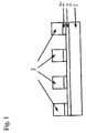
- FIG. 1 shows by way of example a component in which semi-finished products of graphite foil coated according to the invention are brazed together.
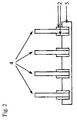
- FIG. 2 shows a heat sink whose fins consist of graphite foils coated in accordance with the invention in the fastening area.
- the metal or metals coated on the graphite foil are selected according to the intended application. Examples include coatings of aluminum or copper, which allow the production of solder joints to other components made of metal or metal-coated materials, as well as coatings of nickel, silver, gold or platinum metals.
- the coating can contain several metals.
- extended surfaces for example webs
- graphite foil If extended surfaces, for example webs, are to be coated from graphite foil, then, for example, by means of continuous vapor deposition with the desired metal.
- a plastic film for example a film made of PET, in order to increase the tensile strength.
- the graphite foil On the non-laminated surface, the graphite foil is now vapor-coated on one side with metal. The plastic film is mechanically removed again after vapor deposition from the uncoated surface of the graphite foil.
- coated graphite foil according to the invention are also other methods from the group of "PVD” (physical vapor deposition) methods such as coating by sputtering and by ion beam method
- PVD physical vapor deposition
- Alternatives to these production methods are the galvanic or electroless deposition of the metal layer.
- certain areas of the surface of the graphite foil may be masked so that they remain uncoated.
- certain structures patterns
- Graphite foils initially coated on one side with metal can be produced by laminating two single-sided coated foils, the coated surfaces facing outwards, on both sides, ie on both outer sides, with metal-coated laminates of graphite foils.
- vapor deposition systems which make lower demands on the tensile strength of the film to be coated, so that no lamination is necessary, a two-sided coating in one pass is possible.
- the graphite foils to be coated have a density of at most 1.9 g / cm 3 , preferably from 0.3 to 1.9 g / cm 3 and particularly preferably from 0.3 to 1.3 g / cm 3 .
- the graphite foil may be coated with a resin or the like prior to applying the metal layer. be impregnated to fill the pores in the film and shoot. This prevents the metal to be deposited on the film from getting inside the film.
- impregnation of the film prior to the galvanic or electroless deposition of metal from an electrolyte bath because the impregnation reduces the penetration of the liquid electrolyte into the pores and thus reduces the expense for the subsequent drying of the coated film.
- the metal-coated graphite foils according to the invention can be used, for example, for the transmission, dissipation and distribution of heat, for example in electronic devices.
- the use of graphite foil for thermal management in electronic devices is known, for example, from the patent US Pat. No. 6,482,520 This document discloses a thermal management device comprising a heat source in contact on one of its outer surfaces with a heat-dissipating graphite foil, a so-called thermal interface.
- the surface of the graphite foil facing away from the heat source is in contact with a heat sink.
- Coated graphite films according to the invention can be used for example for the production of heat exchangers, heat sinks or bipolar cooling plates for fuel cell stacks.
- the inventive combination of lateral conduction of electric current or heat in the graphite foil and isotropic conduction of electric current or heat in the Metal layer be exploited.
- the required semi-finished products for example square or rectangular pieces of foil or film strips, are cut or punched out of the graphite foil coated according to the invention.
- the desired semifinished products could be cut or punched out of an uncoated film web and then coated.
- This approach has the advantage that in addition to the flat sides, the edges of the semi-finished products can be provided with the metal coating, so that the semi-finished products are protected in the area of the edges against the breaking, peeling or flaking of graphite particles.
- Laminates of metal-coated graphite foils can also be used as semi-finished products for the construction of three-dimensional structures.
- a thin adhesive layer can be applied to the metal coating.
- this should be as thin as possible in order not to impair the heat transfer to the metal layer. Good results were achieved with 10 ⁇ m thick adhesive layers.
- the non-metal-coated side of the graphite foil is also provided for attachment to another component, this can be done in the same way with a thin layer of adhesive. The application of the adhesive can be done immediately before use.
- metal coated graphite sheets may be prefabricated with an adhesive layer on the metal layer and / or on the non-metal coated surface which is covered with a peelable plastic film and peeled off just prior to use.
- a sheet of graphite foil having a thickness of 0.4 mm and a density of 1.2 g / cm 3 was laminated on one side with PET film of 12 ⁇ m in thickness to increase the tensile strength of the graphite foil.
- the length of the film was about 50 m, the width about 1 m.
- This film composite of graphite and PET film was vapor-deposited on one side on the non-PET film-covered surface of the graphite foil with aluminum in a continuous high-vacuum coating system. The running speed of the film in the coating system was about 5 m / s.
- To determine the thickness of the aluminum layer a 30 ⁇ 70 mm 2 sample of the coated film composite was punched. The PET film was mechanically removed from the sample.
- Atomic emission spectroscopy was used to determine the aluminum content of the remaining graphite-aluminum layer composite (260 ⁇ g). From the area of the sample and the mass of the aluminum layer, the area-related mass of the aluminum layer was determined (0.12 g / m 2 ). Based on the density of aluminum (2.7 g / cm 3 ), the thickness of the vapor-deposited aluminum layer was calculated to be approximately 45 nm.
- the film strips to be soldered were placed on the aluminum-coated side of the coated graphite foil according to the method described in Example 1 and installed between two plates, which were used for fixing in a cold oven.
- the oven was heated to 650 ° C in about 2 hours. This temperature was held for 20 min, then the samples were cooled in the oven.
- the soldered foil strips adhered very well to the graphite foil.
- the PET foil laminated with aluminum during the vacuum coating of the graphite foil burnt off without backflow during the kiln travel. Due to the relatively slow heating bubble formation was prevented by outgassing of the film.
- the thickness of the soldered plates increases by about 0.4 mm (solder layer) at the superimposed points. An aluminum layer can no longer be determined optically at these locations. From the structure produced in accordance with FIG. 1, by soldering a further coated graphite foil according to the invention onto the strips 3 soldered on the first graphite foil 1, a channel structure can be formed which can be used inter alia in heat exchangers
- the heat sink according to Figure 2 contains cooling fins 4 made of graphite foil, which protrude from a base plate 5 and dissipate heat therefrom.
- a base plate 5 On the surface of the base plate 5, which is usually made of metal, recesses for receiving the cooling fins 4 are provided.
- the cooling fins 4 are soldered in the recesses of the base plate.
- the cooling fins 4 made of graphite foil are provided with a metal coating according to the invention, at least in the region of their surface which projects into the recess (the fastening region).
- a base plate made of graphite may be used, in which the wall surfaces of the recesses are coated with metal, so that graphite foil fins, which in the Attachment area are provided with a metal coating according to the invention can be fixed by means of soldering in the recesses of the base plate.
Landscapes
- Chemical & Material Sciences (AREA)
- Engineering & Computer Science (AREA)
- Ceramic Engineering (AREA)
- Organic Chemistry (AREA)
- Materials Engineering (AREA)
- Chemical Kinetics & Catalysis (AREA)
- Structural Engineering (AREA)
- Manufacturing & Machinery (AREA)
- Life Sciences & Earth Sciences (AREA)
- Sustainable Development (AREA)
- Inorganic Chemistry (AREA)
- Sustainable Energy (AREA)
- General Chemical & Material Sciences (AREA)
- Electrochemistry (AREA)
- Mechanical Engineering (AREA)
- Metallurgy (AREA)
- Composite Materials (AREA)
- General Life Sciences & Earth Sciences (AREA)
- Geology (AREA)
- Laminated Bodies (AREA)
- Carbon And Carbon Compounds (AREA)
- Cooling Or The Like Of Semiconductors Or Solid State Devices (AREA)
- Cooling Or The Like Of Electrical Apparatus (AREA)
Abstract
Die vorliegende Erfindung betrifft Graphitfolien mit einer höchstens 100 nm dicken Metallbeschichtung sowie deren Herstellung, beispielsweise durch kontinuierliches Bedampfen von Graphitfolie, und Verwendung. Trotz der nur geringen Dicke der Metallschicht lassen sich die Graphitfolien durch Löten miteinander oder mit anderen Bauteilen aus Metall oder metallbeschichteten Werkstoffen verbinden. Außerdem schützt die dünne Metallbeschichtung die Oberfläche der Graphitfolie gegen das Herausbrechen, Abblättern oder Abplatzen von Partikeln.
Description
- Die vorliegende Erfindung betrifft Graphitfolien mit einer höchstens 100 nm dicken Metallbeschichtung sowie deren Herstellung und Verwendung.
- Graphitfolie wird durch Verdichten und Zusammenpressen von Graphitexpandat hergestellt. Graphitexpandat entsteht, wenn Graphiteinlagerungsverbindungen bzw. Graphitsalze, z.B. Graphithydrogensulfat oder Graphitnitrat, schockartig erhitzt werden. Dabei vergrößert sich das Volumen der Graphitpartikel um den Faktor 200 bis 400, und die Schüttdichte sinkt auf 2 bis 20 g/l. Das so erhaltene Graphitexpandat besteht aus wurm- oder ziehharmonikaförmigen, sperrigen Aggregaten. Werden diese Partikel unter Druck verdichtet, so verhaken und verzahnen sie sich untereinander. Aufgrund dieses Effekts lassen sich ohne Binderzusatz selbsttragende flächige Gebilde, z.B. Folien oder Platten, herstellen. Graphitfolie zeichnet sich aus durch hohe elektrische und thermische Leitfähigkeit in der Ebene, d.h. senkrecht zur Pressrichtung, und leichte Anpassung an benachbarte Oberflächen.
- Für bestimmte Anwendungen ist es nötig, Graphitfolie an mindestens einer Oberfläche vollflächig oder teilweise mit einer Beschichtung aus Metall zu versehen. Diese Beschichtung kann verschiedene Funktionen erfüllen wie mechanische Verstärkung, Steigerung der thermischen und elektrischen Leitfähigkeit und Korrosionsschutz. Außerdem wird eine metallische Oberfläche insbesondere dann benötigt, wenn die Bauteile aus Graphitfolie durch Lötstellen oder Schweißverbindungen mit anderen, insbesondere metallischen Bauteilen oder mit anderen Bauteilen aus expandiertem Graphit verbunden werden sollen.
- Das Patent
US 5 100 737 offenbart flexible Schichtverbunde aus mindestens einer Lage Graphitfolie mit einer Metallschicht, beispielsweise aus Kupfer oder Nickel, auf mindestens einer ihrer Oberflächen. Die Dicke der Graphitfolie beträgt 0,1 bis 10 mm, die der Metallschicht 1 bis 200 µm, bevorzugt zwischen 3 und 50 µm. Die Schichtverbunde werden angewendet in elektrischen Abschirmungen, Dichtungen oder als Kühlkörper (heat sink). Gegebenenfalls sind auf den Graphit- oder/und Metallschichten zusätzliche Bindungsschichten vorgesehen, um mehrere derartige Schichtverbunde miteinander zu verbinden. Die Bindungsschicht kann als eine dünne Metallschicht (Dicke 1 bis 5 µm) oder als Adhäsivschicht ausgebildet sein. - Die Herstellung der Metallschichten erfolgt vorzugsweise durch chemische (d.h. stromlos mittels eines Reduktionsmittels) oder galvanische Abscheidung. Zwar werden andere Verfahren zur Metallbeschichtung, wie Besprühen mit dem geschmolzenen Metall, Thermisches Spritzen, Vakuumabscheidungstechniken oder CVD nicht grundsätzlich ausgeschlossen, jedoch sind diese Methoden wegen ihrer mangelnden Eignung für den kontinuierlichen Betrieb weniger bevorzugt. Außerdem werden die Schwierigkeiten, mit diesen Techniken dünne Schichten zu erzielen, hervorgehoben.
- Aus dem Patent
DE 28 17 371 C2 sind ebenfalls metallbeschichtete Graphitfolien bekannt. Stapelanordnungen solcher metallbeschichteter Graphitfolien werden als Schleifkörper in Kontaktbürsten elektrischer Maschinen eingesetzt. Das Aufbringen der Schicht kann nach den bekannten Dünnschichtverfahren erfolgen wie Elektroplattieren, chemisches stromloses Plattieren, Plasma- oder Ionenplattieren, Sputtern oder Aufdampfen. Die Aufdampftechnik ist bevorzugt, da hier eine besonders gute Haftung des Metalls an der Graphitfolie erreicht wird. In jedem Fall ist bei der Beschichtung eine Erwärmung der Graphitfolie auf mehr als 100 °C zu vermeiden, weil die Graphitfolie sonst zu stark ausgast und dadurch die Haftung des Metalls vermindert wird. Die Dicke der aufgebrachten Schichten liegt zwischen 0,1 und 500 µm, bevorzugt zwischen 1 und 50 µm. - Die vorliegende Erfindung betrifft Graphitfolie mit einer zumindest einseitigen, Metallbeschichtung, wobei die Metallschicht eine Dicke von höchstens 100 nm aufweist.
Insbesondere betrifft die Erfindung auch flächige, streifenförmige o.ä. Halbzeug aus Graphitfolie, wobei mindestens eine der Flachseiten und mindestens einer der Kanten des Halbzeugs eine metallische Beschichtung mit einer Dicke von höchstens 100 nm aufweist.
Die erfindungs gemäßen beschichteten Graphitfolien weisen mehrere vorteilhafte Eigenschaften auf. So wurde überraschenderweise festgestellt, dass sich trotz der nur geringen Dicke der Metallschicht die erfindungsgemäßen Grraphitfolien ohne Schwierigkeiten durch Löten mit anderen Bauteilen aus Metall oder metallbeschichtetem Graphit verbinden lassen.
Außerdem bewirkt die dünne Metallbeschichtung einen hervorragenden Schutz der Oberfläche der Graphitfolie und ggf. auch der Kanten eines Halbzeugs aus Graphitfolie gegen das Herausbrechen, Abblättern oder Abplatzen von Graphitpartikeln.
Eine weitere Aufgabe der Erfindung besteht darin, ein Verfahren bereitzustellen, um auf Graphitfolie Metallbeschichtungen herzustellen, deren Dicke 100 nm nicht überschreitet. - Die Erfindung betrifft ferner Kombinationen solcher beschichteten Graphitfolien sowie deren Anwendung.
Weitere Details und Vorzüge der Erfindung gehen aus der folgenden detaillierten Beschreibung und den Ausführungsbeispielen und Figuren hervor. - Figur 1 zeigt beispielhaft ein Bauteil, in welchem Halbzeuge aus erfindungsgemäß beschichteter Graphitfolie miteinander verlötet sind.
Figur 2 zeigt einen Kühlkörper, dessen Finnen aus im Befestigungsbereich erfindungsgemäß beschichteten Graphitfolien bestehen. - Das Metall oder die Metalle, mit denen die Graphitfolie beschichtet wird, werden entsprechend der beabsichtigten Anwendung ausgewählt. Beispielhaft genannt seien Beschichtungen aus Aluminium oder Kupfer, welche die Herstellung von Lötverbindungen zu anderen Bauteilen aus Metall oder metallbeschichteten Werkstoffen ermöglichen, sowie Beschichtungen aus Nickel, Silber, Gold oder Platinmetallen. Die Beschichtung kann mehrere Metalle enthalten.
- Sollen ausgedehnte Flächen, beispielsweise Bahnen, aus Graphitfolie beschichtet werden, dann erfolgt beispielsweise mittels kontinuierlicher Bedampfung mit dem gewünschten Metall. Abhängig von der verwendeten Anlage kann es dabei vorteilhaft sein, die Graphitfolie durch einseitiges Kaschieren mit einer Kunststofffolie, z.B. einer Folie aus PET, zu verstärken, um die Reißfestigkeit zu erhöhen. Auf der unkaschierten Oberfläche wird die Graphitfolie nun einseitig mit Metall bedampft. Die Kunststofffolie wird nach erfolgter Bedampfung mechanisch wieder von der unbeschichteten Oberfläche der Graphitfolie entfernt.
Jedoch ist die Erfindung nicht an dieses Verfahren gebunden, zur Herstellung der erfindungsgemäßen beschichteten Graphitfolie geeignet sind auch andere Verfahren aus der Gruppe der "PVD"-Verfahren (physical vapour deposition) wie beispielsweise Beschichtung durch Zerstäuben (Sputtern) und durch Ionenstrahlverfahren
Alternativen zu diesen Herstellungsverfahren bestehen in der galvanischen oder stromlosen Abscheidung der Metallschicht. - Anstelle einer kontinuierlichen Bahn aus Graphitfolie können auch einzelne Halbzeuge aus Graphitfolie, die bereits die für die beabsichtigte Anwendung benötigte Größe und Form aufweisen, beispielsweise quadratische oder rechteckige Folienstücke oder Folienstreifen, mit einer Metallschicht eine Dicke von höchstens 100 nm versehen werden. Unter Halbzeug werden hier allgemein Gebilde aus Graphitfolie mit im Gegensatz zu kontinuierlichen Folienbahnen begrenzter flächiger Ausdehnung verstanden, wobei die Form dieser Fläche beliebig ist und sich im wesentlichen nach der beabsichtigen Anwendung richtet.
Diese Vorgehensweise hat den Vorteil, dass neben den Flachseiten auch die Kanten der Folienstücke beschichtet werden können. Beim Hantieren, Verarbeiten, Einbauen usw. sind nämlich insbesondere die Kanten der flächigen, streifenförmigen o.ä. Halbzeuge mechanischen Belastungen durch Stoß o.ä. ausgesetzt. Daher ist es ein besonders erwünscht, neben den Flachseiten auch die Kanten durch eine geeignete Beschichtung gegen das Herausbrechen, Abblättern oder Abplatzen von Graphitpartikeln zu schützen. Dies wird durch die Beschichtung gemäß der vorliegenden Erfindung ermöglicht.
Beim Bedampfungsverfahren muss ggf., um Abschattungseffekte an den Kanten der Folienstücke zu vermeiden, die Positionierung bzw. Ausrichtung der Bedampfungsquelle entsprechend variiert werden. - Falls gewünscht, können bestimmte Bereiche der Oberfläche der Graphitfolie maskiert werden, so dass sie unbeschichtet bleiben. So können durch die Beschichtung ausgewählter Bereiche auf der Oberfläche der Graphitfolie bestimmte Strukturen (Muster) gebildet werden.
- Aus zunächst einseitig mit Metall beschichteten Graphitfolien können durch Laminieren von zwei einseitig beschichteten Folien, wobei die beschichteten Oberflächen jeweils nach außen gewandt sind, beidseitig, d.h. an beiden Außenseiten, mit Metall beschichtete Laminate aus Graphitfolien hergestellt werden.
Alternativ ist bei der Verwendung von Bedampfungsanlagen, die niedrigere Anforderungen an die Zugfestigkeit der zu beschichtenden Folie stellen, so dass keine Kaschierung nötig ist, auch eine beidseitige Beschichtung in einem Durchlauf möglich. - Die zu beschichtenden Graphitfolien haben eine Dichte von maximal 1,9 g/cm3, bevorzugt von 0,3 bis 1,9 g/cm3 und besonders bevorzugt von 0,3 bis 1,3 g/cm3.
Falls erforderlich, kann die Graphitfolie vor dem Aufbringen der Metallschicht mit einem Harz o.ä. imprägniert werden , um die Poren in der Folie zu füllen und zu schhießen. Dadurch wird verhindert, dass das auf der Folie abzuscheidende Metall ins Innere der Folie gelangt. - Besonders vorteilhaft ist eine Imprägnierung der Folie vor der galvanischen oder stromlosen Abscheidung von Metall aus einem Elektrolytbad, weil durch die Imprägnierung das Eindringen des flüssigen Elektrolyts in die Poren vermindert und so der Aufwand für die anschließende Trocknung der beschichteten Folie reduziert wird.
- Die erfindungsgemäßen metallbeschichteten Graphitfolien können beispielsweise zur Übertragung, Ableitung und Verteilung von Wärme, z.B. in elektronischen Geräten benutzt werden.
Die Verwendung von Graphitfolie zum Wärmemanagement in elektronischen Geräten ist beispielsweise aus der PatentschriftUS 6 482 520 bekannt Dieses Dokument offenbart eine Wärmemanagement-Vorrichtung umfassend eine Wärmequelle, die an einer ihrer äußeren Oberflächen mit einer der Wärmeableitung dienenden Graphitfolie, einem sogenannten Thermal Interface, in Kontakt steht. Optional steht die von der Wärmequelle abgewandte Oberfläche der Graphitfolie mit einem Kühlkörper in Kontakt. In einer in der PatentanmeldungUS 2002/0163076 beschriebenen Weiterentwicklung dieses Thermal Interface wird vorgeschlagen, zur Vermeidung des Abblätterns von Graphitfolie die von der Wärmequelle abgewandte Oberfläche und ggf. auch die Kanten der Folie mit einer Schutzbeschichtung zu versehen. Es wurden Beschichtungen aus verschiedenen Kunststoffen vorgeschlagen. Diese Beschichtungen sind jedoch thermisch kaum leitfähig, so dass die eigentliche Funktion des Thermal Interface, Wärme abzuleiten, dadurch beeinträchtigt wird.
Im Gegensatz dazu verbinden die erfindungsgemäß vorgeschlagenen Metallbeschichtungen den Vorteil des Schutzes der Oberfläche gegen das Abblättern von Graphitpartikeln mit dem Vorteil thermischer Leitfähigkeit.
In Graphitfolie ist die Wärmeleitfähigkeit anisotrop ausgebildet mit Bevorzugung der Wärmeleitung in der Folienebene, in Metallen hingegen isotrop. Innerhalb der Graphitfolie kann also wegen der bevorzugt lateralen Wärmeausbreitung eine weite flächige Verteilung der Wärme erfolgen, während durch die Metallschicht, die aufgrund ihrer Isotropie auch quer zur Folienebene in hohem Maße Wärme leitet, die Einleitung von Wärme in die Graphitfolie oder die Ableitung von Wärme aus derselben bewirkt werden kann. - Aufgrund der Möglichkeit, Löt- und Schweißverbindungen herzustellen, lassen sich aus passend geformten flächigen Halbzeugen aus den erfindungsgemäßen beschichteten Graphitfolien, ggf. in Verbindung mit Bauteilen aus anderen metallbeschichteten Werkstoffen oder aus Metall, dreidimensionalen Strukturen aufbauen. Auf diese Weise können die erfindungsgemäßen beschichteten Graphitfolien beispielsweise zur Herstellung von Wärmetauschern, Kühlkörpern oder bipolaren Kühlplatten für Brennstoffzellenstacks verwendet werden. In diesen und weiteren denkbaren Anwendungen kann neben dem Vorteil der Erfindung, die Herstellung von Löt- und Schweißverbindungen zu ermöglichen, auch die erfindungsgemäße Kombination aus lateraler Leitung von elektrischem Strom bzw. Wärme in der Graphitfolie und isotroper Leitung von elektrischem Strom bzw. Wärme in der Metallschicht, ausgenutzt werden.
Die benötigten Halbzeuge, beispielsweise quadratische oder rechteckige Folienstücke oder Folienstreifen, werden aus der erfindungsgemäß beschichteten Graphitfolie ausgeschnitten oder ausgestanzt. Alternativ könnten auch aus einer unbeschichteten Folienbahn die gewünschten Halbzeuge ausgeschnitten oder ausgestanzt und diese dann beschichtet werden. Diese Vorgehensweise hat den Vorteil, dass neben den Flachseiten auch die Kanten der Halbzeuge mit der Metallbeschichtung versehen werden können, so dass die Halbzeuge auch im Bereich der Kanten gegen das Herausbrechen, Abblättern oder Abplatzen von Graphitpartikeln geschützt sind.
Auch Laminate aus metallbschichteten Graphitfolien können als Halbzeuge für den Aufbau dreidimensionaler Strukturen eingesetzt werden. - Für Anwendungsfälle, bei denen ein Befestigen der metallbeschichteten Graphitfolie mittels Löten oder Schweißen nicht möglich oder nicht geeignet ist, kann auf die Metallbeschichtung eine dünne Klebstoffschicht aufgetragen werden. Diese sollte jedoch so dünn wie möglich sein, um den Wärmeübergang zur Metallschicht nicht zu beeinträchtigen. Gute Ergebnisse wurden mit 10 µm dicken Klebstoffschichten erzielt.
Ist die nicht mit Metall beschichteten Seite der Graphitfolie ebenfalls zur Befestigung an einem anderen Bauteil vorgesehen, kann dies auf die gleiche Weise mit einer dünnen Klebstoffschicht geschehen.
Der Auftrag des Klebstoffs kann unmittelbar vor der Anwendung erfolgen. Alternativ können metallbeschichtete Graphitfolien mit einer Klebstoffschicht auf der Metallschicht oder/und auf der nicht mit Metall beschichteten Oberfläche vorgefertigt werden, die mit einer abziehbaren Kunststoffolie bedeckt und erst unmittelbar vor dem Gebrauch abgezogen wird. - Eine Bahn Graphitfolie mit der Dicke 0,4 mm und der Dichte 1,2 g/cm3 wurde einseitig mit PET-Folie der Dicke 12 µm kaschiert, um die Zugfestigkeit der Graphitfolie zu steigern. Die Länge der Folie betrug ca. 50 m, die Breite ca. 1 m. Dieser Folienverbund aus Graphit- und PET-Folie wurde in einer kontinuierlich arbeitenden Hochvakuum-Beschichtungsanlage einseitig auf der nicht von PET-Folie bedeckten Oberfläche der Graphitfolie mit Aluminium bedampft. Die Laufgeschwindigkeit der Folie in der Beschichtungsanlage betrug ca. 5 m/s. Zur Bestimmung der Dicke der Aluminiumschicht wurde eine 30 x 70 mm2 große Probe aus dem beschichteten Folienverbund gestanzt. Die PET-Folie wurde mechanisch von der Probe entfernt. Mittels Atomemissionsspektroskopie (ICP-AES) wurde der Aluminiumgehalt des verbleibenden Graphit-Aluminium Schichtverbunds bestimmt (260 µg). Aus der Fläche der Probe und der Masse der Aluminiumschicht wurde die flächenbezogene Masse der Aluminiumschicht ermittelt (0,12 g/m2). Anhand der Dichte von Aluminium (2,7 g/cm3) wurde daraus die Dicke der aufgedampften Aluminiumschicht zu ca. 45 nm berechnet.
- Auf eine entsprechend Ausführungsbeispiel 1 einseitig mit einer dünnen Aluminiumbeschichtung 2 versehene Graphitfolie 1 wurden Streifen 3 aus weiterer einseitig mit Aluminium 2' beschichteter Graphitfolie gelötet (siehe Figur 1)
Dazu wurde zunächst kommerziell erhältliches Hartlötpulver, das unter der Bezeichnung "Amasan" (Hersteller: Fa. Armack GmbH - Löttechnik) vertrieben wird und zum Löten von Aluminium und Leichtmetall ALU22 geeignet ist, mit Wasser angeteigt. Diese Masse wurde mit einem Pinsel auf die mit Aluminium beschichtete Seite der zu verlötenden Folienstreifen aufgebracht und mit Aluminiumpulver der Partikelgröbe < 100 µm (Hersteller: Fa. Schlenk Metallpulver GmbH & Co. KG) bestreut. Anschließend wurden die zu verlötenden Folienstreifen auf die mit Aluminium beschichtete Seite der nach dem in Ausführungsbeispiel 1 beschriebenen Verfahren beschichteten Graphitfolie gelegt und zwischen zwei Platten, die zur Fixierung dienten, in einen kalten Ofen eingebaut. Der Ofen wurde in ca. 2 h auf 650 °C aufgeheizt. Diese Temperatur wurde für 20 min gehalten, anschließend kühlien die Proben im Ofen aus.
Die aufgelöteten Folienstreifen hafteten sehr gut auf der Graphitfolie. Die zur Verstärkung während der Vakuumbeschichtung der Graphitfolie mit Aluminium auflaminierte PET-Folie brannte während der Ofenfahrt rückstaudsfrei ab. Durch die relativ langsame Aufheizung wurde Blasenbildung durch Ausgasen der Folie unterbunden.
Die Dicke der gelöteten Platten erhöht sich um ca. 0,4 mm (Lötschicht) an den übereinanderliegenden Stellen. Eine Aluminiumschicht kann optisch an diesen Stellen nicht mehr festgestellt werden.
Aus der so hergestellte Struktur entsprechend Figur 1 kann durch Auflöten einer weiteren erfindungsgemäßen beschichteten Graphitfolie auf die auf der ersten Graphitfolie 1 aufgelöteten Streifen 3 eine Kanalstruktur gebildet werden, die u.a. in Wärmetauschern einsetzbar ist. - In einem Vergleichsversuch wurden nach dem in vorstehend beschriebenen Verfahren Streifen von nicht beschichteter Graphitfolie auf nicht beschichtete Graphitfolie gelötet. Die Haftung zwischen den verlöteten Teilen war bei diesem Versuch deutlich geringer als bei den Lötverbindungen zwischen mit Aluminium beschichteten Graphitfolien. Einige der Streifen lösten sich komplett, andere zumindest teilweise von der Unterlage ab.
- Der Kühlkörper gemäß Figur 2 enthält Kühlfinnen 4 aus Graphitfolie, die aus einer Grundplatte 5 herausragen und von dieser Wärme abführen. An der Oberfläche der Grundplatte 5, welche üblicherweise aus Metall besteht, sind Ausnehmungen zur Aufnahme der Kühlfinnen 4 vorgesehen. Die Kühlfinnen 4 sind in den Ausnehmungen der Grundplatte eingelötet. Dafür sind die Kühlfinnen 4 aus Graphitfolie zumindest in dem Bereich ihrer Oberfläche, der in die Ausnehmung hineinragt (der Befestigungsbereich), mit einer erfindungsgemäßen Metallbeschichtung versehen.
Alternativ kann eine Grundplatte aus Graphit verwendet werden, in welcher die Wandflächen der Ausnehmungen mit Metall beschichtet sind, so dass Finnen aus Graphitfolie, die im Befestigungsbereich mit einer erfindungsgemäßen Metallbeschichtung versehen sind, mittels Löten in den Ausnehmungen der Grundplatte befestigt werden können.
Claims (15)
- Graphitfolie mit einer metallischen Beschichtung auf mindestens einer Oberfläche, dadurch gekennzeichnet, dass die Dicke der Beschichtung höchstens 100 nm beträgt.
- Metallbeschichtete Graphitfolie nach Anspruch 1, dadurch gekennzeichnet, dass die Beschichtung mindestens eins der Metalle Aluminium, Kupfer Nickel, Silber, Gold oder Platinmetalle enthält.
- Metallbeschichtete Graphitfolie nach Anspruch 1, dadurch gekennzeichnet, dass die Graphitfolie mit einem Harz imprägniert ist.
- Metallbeschichtete Graphitfolie nach Anspruch 1 bis 3, dadurch gekennzeichnet, dass nur ausgewählte Bereiche der Oberfläche der Graphitfolie mit Metall beschichtet sind.
- Metallbeschichtete Graphitfolie nach einem der Ansprüche 1 bis 4, dadurch gekennzeichnet, dass sich auf der Metallschicht oder/und auf der nicht mit Metall beschichteten Oberfläche eine Klebstoffschicht mit einer Dicke bis zu 10 µm befindet, die durch eine abziehbare Folie bedeckt ist.
- Laminat aus zwei einseitig metallbeschichteten Graphitfolien gemäß Anspruch 1, wobei die Graphitfolien so angeordnet sind, dass ihre metallbeschichteten Oberflächen nach außen weisen, so dass beide Außenseiten des Laminats eine Metallbschichtung aufweisen.
- Flächiges oder streifenförmiges Halbzeug aus Graphitfolie, dadurch gekennzeichnet, dass mindestens eine der Flachseiten und mindestens eine der Kanten des Halbzeugs eine metallische Beschichtung mit einer Dicke von höchstens 100 nm aufweisen.
- Verwendung von metallbeschichteter Graphitfolie nach einem der Ansprüche 1 bis 5 Laminaten aus metallbeschichteter Graphitfolie nach Anspruch 6 bzw. Halbzeugen nach Anspruch 7 zur Übertragung, Ableitung oder Verteilung von Wärme, insbesondere in elektronischen Geräten.
- Verwendung von metallbeschichteter Graphitfolie nach einem der Ansprüche 1 bis 4, Laminaten aus metallbeschichteter Graphitfolie nach Anspruch 6 bzw. Halbzeugen nach Anspruch 7 zur Herstellung von Wärmetauschern, Kühlkörpern oder bipolaren Kühlplatten für Brennstoffzellenstacks.
- Verfahren zum Verbinden von Halbzeugen oder Bauteilen aus metallbeschichteter Graphitfolie nach einem der Ansprüche 1 bis 4, Laminaten nach Anspruch 6 bzw. Halbzeugen nach Anspruch 7 miteinander oder mit Halbzeugen oder Bauteilen aus anderen metallbeschichteten Werkstoffen oder aus Metall, dadurch gekennzeichnet, dass die Bauteile miteinander verlötet oder verschweißt werden.
- Kühlkörper umfassend Kühlfinnen aus Graphitfolie und eine Grundplatte aus Metall mit Ausnehmungen oder eine Grundplatte aus Graphit mit Ausnehmungen, deren Wände metallbeschichtet sind, wobei die Finnen in den Ausnehmungen eingelötet sind,
dadurch gekennzeichnet dass
die Kühlfinnen aus Graphitfolie zumindest im in die Ausnehmungen hinein ragenden Oberflächenbereich mit einer Metallschicht gemäß Anspruch 1 beschichtet sind. - Verfahren zur Herstellung einer einseitigen metallischen Beschichtung auf Graphitfolie, umfassend die Schritte• einseitiges Kaschieren einer Bahn aus Graphitfolie mit einer Kunststofffolie• kontinuierliches Bedampfen mit dem gewünschten Metall in der gewünschten Schichtdicke• mechanisches Entfernen der Kaschierung
- Verfahren nach Anspruch 12, dadurch gekennzeichnet, dass die Graphitfolie mit einer Folie aus PET kaschiert wird.
- Verfahren nach Anspruch 12, dadurch gekennzeichnet, dass die Graphitfolie mit einem Harz imprägniert ist.
- Verfahren nach Anspruch 12, dadurch gekennzeichnet, dass ausgewählte Oberflächenbereiche, die unbeschichtet bleiben sollen, mit einer Maskierung abgedeckt werden.
Priority Applications (7)
| Application Number | Priority Date | Filing Date | Title |
|---|---|---|---|
| EP05013340A EP1746077A1 (de) | 2005-06-21 | 2005-06-21 | Metallbeschichtete Graphitfolie |
| PCT/EP2006/004601 WO2006136242A1 (de) | 2005-06-21 | 2006-05-16 | Metallbeschichtete graphitfolie |
| JP2008517344A JP2009505850A (ja) | 2005-06-21 | 2006-05-16 | 金属被覆されたグラファイトフィルム |
| CNA2006800207871A CN101193837A (zh) | 2005-06-21 | 2006-05-16 | 涂敷有金属的石墨膜 |
| EP06753638A EP1893550A1 (de) | 2005-06-21 | 2006-05-16 | Metallbeschichtete graphitfolie |
| KR1020087001501A KR20080031741A (ko) | 2005-06-21 | 2006-05-16 | 금속-코팅된 그래파이트 시트 |
| US11/962,440 US20080149322A1 (en) | 2005-06-21 | 2007-12-21 | Metal Coated Graphite Sheet |
Applications Claiming Priority (1)
| Application Number | Priority Date | Filing Date | Title |
|---|---|---|---|
| EP05013340A EP1746077A1 (de) | 2005-06-21 | 2005-06-21 | Metallbeschichtete Graphitfolie |
Publications (1)
| Publication Number | Publication Date |
|---|---|
| EP1746077A1 true EP1746077A1 (de) | 2007-01-24 |
Family
ID=36758406
Family Applications (2)
| Application Number | Title | Priority Date | Filing Date |
|---|---|---|---|
| EP05013340A Withdrawn EP1746077A1 (de) | 2005-06-21 | 2005-06-21 | Metallbeschichtete Graphitfolie |
| EP06753638A Withdrawn EP1893550A1 (de) | 2005-06-21 | 2006-05-16 | Metallbeschichtete graphitfolie |
Family Applications After (1)
| Application Number | Title | Priority Date | Filing Date |
|---|---|---|---|
| EP06753638A Withdrawn EP1893550A1 (de) | 2005-06-21 | 2006-05-16 | Metallbeschichtete graphitfolie |
Country Status (6)
| Country | Link |
|---|---|
| US (1) | US20080149322A1 (de) |
| EP (2) | EP1746077A1 (de) |
| JP (1) | JP2009505850A (de) |
| KR (1) | KR20080031741A (de) |
| CN (1) | CN101193837A (de) |
| WO (1) | WO2006136242A1 (de) |
Cited By (4)
| Publication number | Priority date | Publication date | Assignee | Title |
|---|---|---|---|---|
| DE102006046518A1 (de) * | 2006-09-29 | 2008-04-10 | Airbus Deutschland Gmbh | Verfahren zum Beschichten eines Substrates |
| DE102008051905A1 (de) * | 2008-10-16 | 2010-07-15 | Sgl Carbon Se | Verfahren zur Herstellung von Wärmetauscherrohren |
| US9764351B2 (en) | 2006-09-29 | 2017-09-19 | Airbus Operations Gmbh | Method of coating a substrate |
| CN109133965A (zh) * | 2018-09-10 | 2019-01-04 | 哈尔滨工业大学 | 一种二维高导热石墨膜/铝复合材料的制备方法 |
Families Citing this family (37)
| Publication number | Priority date | Publication date | Assignee | Title |
|---|---|---|---|---|
| US20070053168A1 (en) * | 2004-01-21 | 2007-03-08 | General Electric Company | Advanced heat sinks and thermal spreaders |
| GB2432830A (en) * | 2005-12-02 | 2007-06-06 | Morganite Elect Carbon | Formation of thermally anisotropic carbon material |
| US20070283709A1 (en) * | 2006-06-09 | 2007-12-13 | Veeco Instruments Inc. | Apparatus and methods for managing the temperature of a substrate in a high vacuum processing system |
| US8919428B2 (en) * | 2007-10-17 | 2014-12-30 | Purdue Research Foundation | Methods for attaching carbon nanotubes to a carbon substrate |
| US8785080B2 (en) * | 2008-01-03 | 2014-07-22 | GM Global Technology Operations LLC | Passivated metallic bipolar plates and a method for producing the same |
| KR101420802B1 (ko) * | 2008-01-17 | 2014-07-21 | 삼성전자주식회사 | 전자모듈용 방열구조체 및 이를 구비한 전자기기 |
| US20110103021A1 (en) * | 2008-03-20 | 2011-05-05 | Robert Hendrik Catharina Janssen | Heatsinks of thermally conductive plastic materials |
| US8541058B2 (en) * | 2009-03-06 | 2013-09-24 | Timothy S. Fisher | Palladium thiolate bonding of carbon nanotubes |
| TW201035513A (en) * | 2009-03-25 | 2010-10-01 | Wah Hong Ind Corp | Method for manufacturing heat dissipation interface device and product thereof |
| US8955580B2 (en) | 2009-08-14 | 2015-02-17 | Wah Hong Industrial Corp. | Use of a graphite heat-dissipation device including a plating metal layer |
| CN101865627B (zh) * | 2009-04-20 | 2013-06-12 | 华宏新技股份有限公司 | 散热界面装置的制作方法及其制品 |
| CN101710493B (zh) * | 2009-05-12 | 2012-03-21 | 大连丽昌新材料有限公司 | 一种石墨散热模组 |
| CN102555340B (zh) * | 2010-12-28 | 2015-08-19 | 碳元科技股份有限公司 | 一种高散热膜复合结构及其制造方法 |
| CN102555325B (zh) * | 2010-12-31 | 2016-01-20 | 碳元科技股份有限公司 | 一种复合固定型高散热膜结构 |
| JP2012175093A (ja) * | 2011-02-21 | 2012-09-10 | Akimichi Nakajo | 熱エネルギーを電気エネルギーに変える熱電発電システム |
| US10347559B2 (en) | 2011-03-16 | 2019-07-09 | Momentive Performance Materials Inc. | High thermal conductivity/low coefficient of thermal expansion composites |
| JP5842349B2 (ja) * | 2011-03-18 | 2016-01-13 | 富士通株式会社 | シート状構造体、シート状構造体の製造方法、電子機器及び電子機器の製造方法 |
| WO2013043813A1 (en) * | 2011-09-21 | 2013-03-28 | Applied Nanotech Holdings, Inc. | Carbon-metal thermal management substrates |
| KR101878739B1 (ko) * | 2011-10-24 | 2018-07-17 | 삼성전자주식회사 | 그래핀 전사부재, 그래핀 전사방법 및 이를 이용한 그래핀 소자 제조방법 |
| US9500418B2 (en) | 2012-01-16 | 2016-11-22 | Kaneka Corporation | Graphite composite film |
| US20150118514A1 (en) * | 2013-10-30 | 2015-04-30 | Teledyne Scientific & Imaging, Llc. | High Performance Thermal Interface System With Improved Heat Spreading and CTE Compliance |
| US20150194241A1 (en) * | 2014-01-09 | 2015-07-09 | The Boeing Company | Electrical conductors and methods of forming thereof |
| WO2015132802A2 (en) | 2014-03-05 | 2015-09-11 | Council Of Scientific & Industrial Research | A process for synthesis of single layer metal sheets |
| CN103897626A (zh) * | 2014-04-18 | 2014-07-02 | 太仓泰邦电子科技有限公司 | 一种导电胶带 |
| CN109874345B (zh) * | 2015-04-15 | 2023-10-31 | 株式会社钟化 | 离子束电荷转换装置的电荷转换膜 |
| JPWO2017086241A1 (ja) * | 2015-11-20 | 2018-09-06 | Jnc株式会社 | 放熱器、電子機器、照明機器および放熱器の製造方法 |
| CN105624608B (zh) * | 2015-12-29 | 2018-05-04 | 上海交通大学 | 一种高导热石墨膜表面金属涂层的制备方法 |
| KR101997120B1 (ko) * | 2016-03-18 | 2019-07-05 | (주)시엔케이 | 전기전도성 카본페이퍼의 제작방법. |
| CN107969091A (zh) * | 2016-10-20 | 2018-04-27 | 上海光线新材料科技有限公司 | 基于加成法的石墨覆铜散热膜及其制备方法 |
| KR20180055017A (ko) * | 2016-11-15 | 2018-05-25 | 주식회사 포스코 | 이중강관 및 이중강관의 제조방법 |
| JP7094805B2 (ja) * | 2018-07-05 | 2022-07-04 | 住友精密工業株式会社 | 熱交換器および熱交換器の製造方法 |
| KR102600004B1 (ko) * | 2018-12-26 | 2023-11-08 | 삼성전자주식회사 | 반도체 패키지 |
| KR102081783B1 (ko) * | 2019-04-03 | 2020-02-27 | (주)시엔케이 | 전기전도성 카본페이퍼의 제작방법 |
| CN110744875A (zh) * | 2019-10-25 | 2020-02-04 | 北京中石伟业科技无锡有限公司 | 一种高导热复合石墨散热片及其制备方法 |
| JP7526938B2 (ja) | 2020-07-30 | 2024-08-02 | パナソニックIpマネジメント株式会社 | ヒートシンク及びその製造方法 |
| DE102020214437A1 (de) * | 2020-11-17 | 2022-05-19 | Sgl Carbon Se | Dichtung |
| KR102946399B1 (ko) * | 2020-12-30 | 2026-04-01 | 엘지전자 주식회사 | 유도 가열시 고 자속 밀도를 갖는 그라파이트 구조체 및 그의 배열 방법 |
Citations (2)
| Publication number | Priority date | Publication date | Assignee | Title |
|---|---|---|---|---|
| DE2817371A1 (de) * | 1978-04-20 | 1979-10-25 | Siemens Ag | Stromuebertragungsbuerste |
| US5100737A (en) * | 1989-11-16 | 1992-03-31 | Le Carbone Lorraine | Multi-layer material comprising flexible graphite which is reinforced mechanically, electrically and thermally by a metal and a process for the production thereof |
Family Cites Families (3)
| Publication number | Priority date | Publication date | Assignee | Title |
|---|---|---|---|---|
| US6245400B1 (en) * | 1998-10-07 | 2001-06-12 | Ucar Graph-Tech Inc. | Flexible graphite with non-carrier pressure sensitive adhesive backing and release liner |
| JP2001079977A (ja) * | 1999-09-14 | 2001-03-27 | Matsushita Electric Ind Co Ltd | 複合体及びその製造方法 |
| US6907917B2 (en) * | 2003-01-10 | 2005-06-21 | International Business Machines Corporation | Graphite-based heat sinks and method and apparatus for the manufacture thereof |
-
2005
- 2005-06-21 EP EP05013340A patent/EP1746077A1/de not_active Withdrawn
-
2006
- 2006-05-16 JP JP2008517344A patent/JP2009505850A/ja active Pending
- 2006-05-16 KR KR1020087001501A patent/KR20080031741A/ko not_active Withdrawn
- 2006-05-16 EP EP06753638A patent/EP1893550A1/de not_active Withdrawn
- 2006-05-16 WO PCT/EP2006/004601 patent/WO2006136242A1/de not_active Ceased
- 2006-05-16 CN CNA2006800207871A patent/CN101193837A/zh active Pending
-
2007
- 2007-12-21 US US11/962,440 patent/US20080149322A1/en not_active Abandoned
Patent Citations (2)
| Publication number | Priority date | Publication date | Assignee | Title |
|---|---|---|---|---|
| DE2817371A1 (de) * | 1978-04-20 | 1979-10-25 | Siemens Ag | Stromuebertragungsbuerste |
| US5100737A (en) * | 1989-11-16 | 1992-03-31 | Le Carbone Lorraine | Multi-layer material comprising flexible graphite which is reinforced mechanically, electrically and thermally by a metal and a process for the production thereof |
Cited By (5)
| Publication number | Priority date | Publication date | Assignee | Title |
|---|---|---|---|---|
| DE102006046518A1 (de) * | 2006-09-29 | 2008-04-10 | Airbus Deutschland Gmbh | Verfahren zum Beschichten eines Substrates |
| DE102006046518B4 (de) * | 2006-09-29 | 2008-10-30 | Airbus Deutschland Gmbh | Verfahren zum Beschichten eines Substrates |
| US9764351B2 (en) | 2006-09-29 | 2017-09-19 | Airbus Operations Gmbh | Method of coating a substrate |
| DE102008051905A1 (de) * | 2008-10-16 | 2010-07-15 | Sgl Carbon Se | Verfahren zur Herstellung von Wärmetauscherrohren |
| CN109133965A (zh) * | 2018-09-10 | 2019-01-04 | 哈尔滨工业大学 | 一种二维高导热石墨膜/铝复合材料的制备方法 |
Also Published As
| Publication number | Publication date |
|---|---|
| WO2006136242A1 (de) | 2006-12-28 |
| US20080149322A1 (en) | 2008-06-26 |
| KR20080031741A (ko) | 2008-04-10 |
| EP1893550A1 (de) | 2008-03-05 |
| JP2009505850A (ja) | 2009-02-12 |
| CN101193837A (zh) | 2008-06-04 |
Similar Documents
| Publication | Publication Date | Title |
|---|---|---|
| EP1893550A1 (de) | Metallbeschichtete graphitfolie | |
| EP3077682B1 (de) | Schichtanordnung zur verbindung von bauteilen | |
| DE3204231C2 (de) | Laminat mit einem Metall-Faser-Verbundmaterial und dessen Verwendung | |
| EP2899019B1 (de) | Thermisches verbindungselement und verfahren zu dessen herstellung | |
| DE102017112999B4 (de) | Elektrische zwischenverbindungen für batteriezellen | |
| DE3217217C2 (de) | Kontaktbürste und Verfahren zu ihrer Herstellung | |
| DE102018107321A1 (de) | Elektrische Zwischenverbindungen für Batteriezellen | |
| EP3233746A1 (de) | Verfahren zur herstellung einer verbundscheibe mit korrosionsgeschützter funktioneller beschichtung | |
| DE112018005786T5 (de) | Plattiertes Material und Verfahren zu dessen Herstellung | |
| EP2327542A1 (de) | Mehrlagiges flexibles Wärmeleitlaminat | |
| DE69508899T2 (de) | Verbundmaterial und Verbundelement mit dadurch sichergestellter elektrischer Kontinuität, dessen Herstellungsverfahren und dessen Verwendung in Flugzeugindustrie | |
| DE102007051570A1 (de) | Verfahren zur Herstellung eines Verbundwerkstoffs sowie Verbundwerkstoff, Verbundwerkstoffkörper und Anschlussvorrichtung | |
| DE102014011887A1 (de) | Elektrisches Anschlusselement, Verfahren zur Herstellung eines elektrischen Anschlusselements sowie Verwendung eines elektrischen Anschlusselements | |
| DE3041957A1 (de) | Thermische abschirmung, insbesondere fuer raumfahrzeuge | |
| EP3161180B1 (de) | Sputtering target | |
| EP3847679B1 (de) | Verfahren zur elektrischen kontaktierung eines supraleitenden bandleiters | |
| EP1401636B1 (de) | Trennblech bzw. verfahren zur herstellung eines trennbleches für ein multilayerpresspaket | |
| EP1688684A1 (de) | Absorberbauteil für solarthermischer Flachkollektor | |
| DE102009022584B4 (de) | Verfahren zum stoffschlüssigen Verbinden von Teilen mit einem Klebstoff | |
| DE69834934T2 (de) | Flexibele wärmeübertragungsvorrichtung und verfahren | |
| DE102013222297A1 (de) | Verfahren zum Verpressen oder Laminieren wenigstens zweier Substrate sowie Trennfolie und Presseinlage für ein entsprechendes Verfahren | |
| DE102009031575A1 (de) | Verfahren zum Verkleiden eines Bauteils mit einer selbst tragenden Verkleidung | |
| DE102014103954A1 (de) | Verstärkungsstrukturen mit wärmeleitfähigkeitserhöhender Beschichtung in Harzmatrix und von Beschichtung getrennte elektrische Leiterstruktur | |
| DE102011008311A1 (de) | Reaktivfolie zum Verlöten von metallischen Bauteilen | |
| DE102021206824B4 (de) | Thermal Interface Material, Energiespeicher mit einem Thermal Interface Material und Verfahren zu deren Herstellung |
Legal Events
| Date | Code | Title | Description |
|---|---|---|---|
| PUAI | Public reference made under article 153(3) epc to a published international application that has entered the european phase |
Free format text: ORIGINAL CODE: 0009012 |
|
| AK | Designated contracting states |
Kind code of ref document: A1 Designated state(s): AT BE BG CH CY CZ DE DK EE ES FI FR GB GR HU IE IS IT LI LT LU MC NL PL PT RO SE SI SK TR |
|
| AX | Request for extension of the european patent |
Extension state: AL BA HR LV MK YU |
|
| AKX | Designation fees paid | ||
| STAA | Information on the status of an ep patent application or granted ep patent |
Free format text: STATUS: THE APPLICATION IS DEEMED TO BE WITHDRAWN |
|
| 18D | Application deemed to be withdrawn |
Effective date: 20070725 |
|
| REG | Reference to a national code |
Ref country code: DE Ref legal event code: 8566 |