EP1745527B1 - Ensemble antenne pour la transmission inductive d'energie et utilisation dudit ensemble antenne - Google Patents
Ensemble antenne pour la transmission inductive d'energie et utilisation dudit ensemble antenne Download PDFInfo
- Publication number
- EP1745527B1 EP1745527B1 EP05741826.1A EP05741826A EP1745527B1 EP 1745527 B1 EP1745527 B1 EP 1745527B1 EP 05741826 A EP05741826 A EP 05741826A EP 1745527 B1 EP1745527 B1 EP 1745527B1
- Authority
- EP
- European Patent Office
- Prior art keywords
- antenna arrangement
- arrangement according
- magnetic
- magnetic core
- windings
- Prior art date
- Legal status (The legal status is an assumption and is not a legal conclusion. Google has not performed a legal analysis and makes no representation as to the accuracy of the status listed.)
- Expired - Lifetime
Links
- 230000001939 inductive effect Effects 0.000 title claims description 11
- 230000005540 biological transmission Effects 0.000 title description 10
- 238000004804 winding Methods 0.000 claims description 32
- 239000002245 particle Substances 0.000 claims description 12
- 230000004907 flux Effects 0.000 claims description 9
- 230000035699 permeability Effects 0.000 claims description 9
- 239000004033 plastic Substances 0.000 claims description 9
- 239000002131 composite material Substances 0.000 claims description 7
- 238000005516 engineering process Methods 0.000 claims description 5
- 230000006698 induction Effects 0.000 claims description 4
- 230000005415 magnetization Effects 0.000 claims description 4
- 238000000034 method Methods 0.000 claims description 3
- 238000005266 casting Methods 0.000 claims description 2
- 239000002707 nanocrystalline material Substances 0.000 claims description 2
- 229920005989 resin Polymers 0.000 claims description 2
- 239000011347 resin Substances 0.000 claims description 2
- 239000002344 surface layer Substances 0.000 claims description 2
- 230000010363 phase shift Effects 0.000 claims 1
- 229920001169 thermoplastic Polymers 0.000 claims 1
- 239000004416 thermosoftening plastic Substances 0.000 claims 1
- 229910045601 alloy Inorganic materials 0.000 description 7
- 239000000956 alloy Substances 0.000 description 7
- 230000008878 coupling Effects 0.000 description 6
- 238000010168 coupling process Methods 0.000 description 6
- 238000005859 coupling reaction Methods 0.000 description 6
- 230000005855 radiation Effects 0.000 description 5
- 238000013461 design Methods 0.000 description 4
- 239000000463 material Substances 0.000 description 4
- 238000004519 manufacturing process Methods 0.000 description 3
- -1 Iron-aluminum-silicon Chemical compound 0.000 description 2
- 229910001035 Soft ferrite Inorganic materials 0.000 description 2
- 230000000694 effects Effects 0.000 description 2
- 239000006247 magnetic powder Substances 0.000 description 2
- 239000000843 powder Substances 0.000 description 2
- 229920001187 thermosetting polymer Polymers 0.000 description 2
- 238000012546 transfer Methods 0.000 description 2
- 229910000859 α-Fe Inorganic materials 0.000 description 2
- XEEYBQQBJWHFJM-UHFFFAOYSA-N Iron Chemical compound [Fe] XEEYBQQBJWHFJM-UHFFFAOYSA-N 0.000 description 1
- 229910001030 Iron–nickel alloy Inorganic materials 0.000 description 1
- 239000004952 Polyamide Substances 0.000 description 1
- 229910000676 Si alloy Inorganic materials 0.000 description 1
- 239000003990 capacitor Substances 0.000 description 1
- 230000006835 compression Effects 0.000 description 1
- 238000007906 compression Methods 0.000 description 1
- 239000004020 conductor Substances 0.000 description 1
- 230000001419 dependent effect Effects 0.000 description 1
- 238000011161 development Methods 0.000 description 1
- 230000018109 developmental process Effects 0.000 description 1
- 239000003822 epoxy resin Substances 0.000 description 1
- 238000000605 extraction Methods 0.000 description 1
- 238000010438 heat treatment Methods 0.000 description 1
- 238000001746 injection moulding Methods 0.000 description 1
- 238000010295 mobile communication Methods 0.000 description 1
- 238000012544 monitoring process Methods 0.000 description 1
- 238000011017 operating method Methods 0.000 description 1
- 230000021715 photosynthesis, light harvesting Effects 0.000 description 1
- 239000006223 plastic coating Substances 0.000 description 1
- 229920000058 polyacrylate Polymers 0.000 description 1
- 229920002647 polyamide Polymers 0.000 description 1
- 229920000647 polyepoxide Polymers 0.000 description 1
- 229920001721 polyimide Polymers 0.000 description 1
- 239000009719 polyimide resin Substances 0.000 description 1
- 238000007712 rapid solidification Methods 0.000 description 1
- 238000007493 shaping process Methods 0.000 description 1
- 230000035939 shock Effects 0.000 description 1
- 238000010301 surface-oxidation reaction Methods 0.000 description 1
- 229920003002 synthetic resin Polymers 0.000 description 1
- 239000000057 synthetic resin Substances 0.000 description 1
Images
Classifications
-
- H—ELECTRICITY
- H01—ELECTRIC ELEMENTS
- H01Q—ANTENNAS, i.e. RADIO AERIALS
- H01Q7/00—Loop antennas with a substantially uniform current distribution around the loop and having a directional radiation pattern in a plane perpendicular to the plane of the loop
- H01Q7/06—Loop antennas with a substantially uniform current distribution around the loop and having a directional radiation pattern in a plane perpendicular to the plane of the loop with core of ferromagnetic material
Definitions
- the invention relates to an antenna arrangement with an open magnetic core and a winding.
- the invention is in the field of magnetic field antennas used for inductive energy transmission.
- it is possible to transmit energy and information by means of electric or magnetic dipoles.
- electromagnetic waves or only predominantly electrical or magnetic fields are generated. It may be desirable not to emit electromagnetic waves but to confine itself to the generation of magnetic fields, for example to avoid exposure to organic tissue around the antenna.
- relatively high energies can be transmitted without a galvanic coupling. The effect of such coupling is limited to a narrow spatial area less than about 1 meter. Nevertheless, there are many possible applications for such a transmission.
- soft magnetic powder composite materials can be used as pressed magnetic cores.
- these may consist of iron powder.
- effective permeabilities between about 10 and 30 can be achieved.
- saturation inductions are approximately 1.0 to 1.4 T.
- powder composite materials of soft magnetic crystalline Iron-aluminum-silicon alloys and iron-nickel alloys are known, with which application frequencies can be achieved to over 100 kHz.
- Magnetic cores are known, which are produced by injection molding of an injection-moldable plastic and a nanocrystalline alloy.
- Corresponding nanocrystalline alloys are for example from EP 0271657 A2 and the EP 0455113 A2 known.
- Such alloys are produced, for example, by means of rapid solidification technology in the form of thin alloy strips which are initially amorphous and which are subjected to a heat treatment to form a nanocrystalline structure.
- Such alloys can be ground to alloy powders having particle sizes less than 2mm.
- so-called flakes with thicknesses between 0.01 and 0.04 mm and widths or lengths of 0.04 to 1 mm per particle arise.
- These flakes can be processed into composite materials using synthetic resins, in which saturation magnetizations greater than 0.5 Tesla and permeabilities between 10 and 200 can be realized.
- a manufacturing method for such magnetic cores is for example in the WO 0191141 A1 shown.
- transponders which also consist of soft magnetic powder composite materials, such as amorphous alloys. Such antennas are used there for the exchange of information.
- the present invention is based on the object of providing an antenna arrangement for use in the inductive transmission of energy, regardless of a precise positioning of the antenna arrangement relative to a receiver.
- the present invention aims at the effective transmission of energy in the near field region and the reliable functioning independently of a precise positioning of the antenna arrangement relative to a receiver, to which the energy is to be transmitted by inductive means.
- the setting of very specific magnetic properties, in particular a sufficient flow with a suitable radiation characteristic in the antenna arrangement is necessary.
- antennas as used in the present antenna arrangement, usually represent the inductive part of a resonant circuit, a high antenna quality of at least 50, preferably even 100 in the range of the operating frequency is desirable for optimizing the energy dissipation.
- a temperature-independent permeability is required, which is for optimal flow control between 30 and 200. With higher permeability, the flux bundling in the core is so good that laterally too low a flow component emerges from the core and the field strength along the core, ie in the receiver region, becomes highly inhomogeneous.
- the object underlying the present invention can not be solved satisfactorily with the known magnet arrangements, magnetic cores and materials.
- the magnetic core contains as a composite material a soft magnetic component of finely divided particles and a plastic component, wherein the magnetic core has an initial permeability between 20 and 200 and a saturation induction> 0.6 T.
- the soft magnetic component advantageously consists of the already mentioned flakes of a nanocrystalline material. This has a saturation magnetization of about 1 to 1.6T and permeabilities> 30,000.
- a plastic component of the magnetic circuit By mixing with a plastic component of the magnetic circuit is through the microscopic gaps between the flakes are interrupted and it is possible to set lower effective permeabilities of 30 to 100 with high quality and temperature stability. Nevertheless, a high achievable flux density greater than 0.6 T, typically greater than 0.9 T.
- the soft magnetic component of the magnetic core also has the advantageous advantage that the particles are each electrically isolated by a surface layer. This can be realized for example by surface oxidation or plastic coating.
- the particle size may advantageously be less than 2 mm, wherein the particle thicknesses may be smaller than 0.5 mm. As a result of this configuration of the particles, particularly low loss of magnetization losses and thus a particularly high quality of the antenna are achieved.
- the mechanical properties can be adjusted with regard to the type and proportion of the plastic used with regard to fracture toughness and flexibility
- thermosets or thermosets such as polyamide, polyacrylate, polyacetate, polyimide or epoxy resin depending on the desired mechanical and thermal properties.
- the antenna arrangement as a magnetic core on a rod or a plate, which are provided with a winding. Certain core cross-sections are necessary to make the arrangement usable for the effective transmission of energy. If an average flux of at least 20 ⁇ Wb is to be achieved in the core, this results in an induction of 400 mT with a cross section of 0.5 cm 2 . This corresponds to about half of the cross section, which would be necessary when using a soft ferrite.
- the coil length of the winding should be greater than its diameter, preferably large compared to the diameter.
- An essential feature of the material used according to the invention is the mechanical insensitivity to shock or vibration and the free shaping during the production or a subsequent flexibility.
- the inventively used material also allows because of its magnetic properties also a small size, as it is desirable for cost, space and design reasons in many applications.
- a plurality of windings may be arranged on the same magnetic core, wherein the longitudinal axes of the windings are at an angle> 0 °, for example 90 ° to each other.
- the windings may be driven simultaneously, out of phase or alternately to reach inductive energy transfer receivers in different positions. This makes the transmission of energy more reliable and less sensitive to the relative positioning of transmitter and receiver.
- the invention also relates to various operating methods of the antenna arrangement according to the invention with intermittent operation of the various windings or the mentioned phase-shifted simultaneous driving of the different windings.
- the antenna arrangement according to the invention is also designed to save space, it may additionally be useful to provide a recess within a magnetic core in which electronic components, for example the drive circuit of the antenna arrangement, can be accommodated.
- the flow guidance within the magnetic core is hardly negatively influenced by such recesses, if they are not too large.
- the antenna arrangement can advantageously be prefabricated with the drive circuit and simply used as an integral unit in a device.
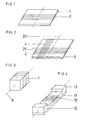
- FIG. 1 shows a flat magnetic core 1 with a winding 2, wherein the dimensions of the magnetic core may be, for example 20 x 10 x 0.2 cm.
- the base area of the core is preferably as large as the target area of a receiver to be covered. Due to the design of the winding, for example, a compression of the windings to the winding ends, a strong as possible homogeneous flux density over the core surface is generated.
- the special design of the flow orientation and the radiation characteristic shows the FIG. 2 a combination of two mutually perpendicular windings 3,4 on a running almost as a square plate magnetic core 5. The two windings can be alternately sequentially or simultaneously out of phase controlled against each other.
- the entire arrangement according to FIG. 1 or 2 be flexible. In any case, however, it is more resistant to breakage than, for example, an antenna with a ferrite core or a core made of another conventional material.
- FIG. 3 Particularly suitable for the transmission of energy to a moving receiver is the in FIG. 3 shown arrangement with a rod-shaped magnetic core, wherein the direction of movement, as well as the antenna of the receiver is directed parallel to the longitudinal axis 6 of the winding 7.
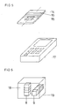
- FIG. 6 are two different magnetic cores 8, 9 shown, each having a separate winding and the longitudinal axes are perpendicular to each other to allow different flux densities and radiation characteristics.
- This is an alternative embodiment to that in the FIG. 2 shown with multiple windings on a single magnetic core.
- FIG. 4 shows an arrangement in which the winding 10 is integrated into a magnetic body 11 in so far as it passes through the magnetic core 11 itself, so that a lower part of the magnetic core 11 in the FIG. 4 forms a yoke that shorts the magnetic flux on the bottom.
- a shielding effect in one direction (down) is achieved with good radiation upwards.
- FIG. 5 shows in the magnetic core 14 has a recess 15, which allows there components of an electronic circuit, for example, to drive the winding 16 to accommodate.
- FIG. 6 shows an application example of the invention- ⁇ en antenna arrangement with a mobile communication terminal, such as a mobile phone or a cordless telephone 17, which has a non-illustrated receiving device for inductive coupling with the antenna assembly 18.
- the antenna arrangement 18 has in a housing 19, the two magnetic cores 8, 9, which are each provided with a winding and inductively can transmit energy to the receiver in the terminal 17.
- a capacitor or battery for storing the transmitted energy is provided in addition to the receiver.
- the same arrangement can also be used for retransmission of information, or a signal which is either also transmitted inductively, which would have to be switched between sending and receiving, or by evaluating the energy extraction of the receiver.
Landscapes
- Soft Magnetic Materials (AREA)
- Details Of Aerials (AREA)
- Near-Field Transmission Systems (AREA)
Claims (11)
- Ensemble antenne comprenant un noyau magnétique (1, 5, 14) et au moins un enroulement (2, 3, 4, 7, 10, 16), par le moyen duquel l'énergie inductive est transmise d'un émetteur à un récepteur sur une distance comprise entre environ 0,5 et 50 cm,
caractérisé en ce que
le noyau magnétique (1, 5, 14) contient un matériau composite, qui comprend un composant faiblement magnétique mélangé avec un composant en plastique, dans lequel le composant faiblement magnétique comprend des particules finement distribuées faites de matériau nanocristallin ayant une magnétisation de saturation de 1 à 1,6 Tesla et une perméabilité supérieure à 30 000, de manière que le noyau magnétique (1, 5, 14) ait une perméabilité initiale efficace comprise entre 20 et 200 et une induction de saturation supérieure à 0,6 Tesla, et que le noyau magnétique (1, 5, 14) ait une capacité de chargement de flux magnétique jusqu'à au moins 20 µWb. - Ensemble antenne selon la revendication 1, dans lequel le composant faiblement magnétique consiste en particules qui sont isolées électriquement individuellement par une couche de surface.
- Ensemble antenne selon la revendication 1 ou 2, dans lequel la taille des particules est de moins de 2 mm.
- Ensemble antenne selon la revendication 1, 2 ou 3, dans lequel les épaisseurs des particules sont de moins de 0,5 mm.
- Ensemble antenne selon l'une des revendications 2 à 4, dans lequel les particules sont oxydées en surface ou revêtues de plastique.
- Ensemble antenne selon l'une des revendications 1 à 5, dans lequel le composant en plastique contient un thermoplastique ou un thermodurcissable, qui peut être traité dans le cadre de techniques utilisant des résines de coulée.
- Ensemble antenne selon l'une des revendications 1 à 6, dans lequel l'antenne formée par le noyau magnétique (1, 5, 14) et le ou les enroulements (2, 3, 4, 7, 10, 16) a une qualité de plus de 50 dans la plage de fréquence comprise entre 20 kHz et 150 kHz.
- Ensemble antenne selon l'une des revendications 1 à 7, comprenant une pluralité d'enroulements (2, 3, 4, 7, 10, 16) sur le même noyau magnétique (1, 5, 14), dans lequel les axes longitudinaux (20, 21) des enroulements sont disposés les uns par rapport aux autres selon un angle de plus 0°.
- Ensemble antenne selon la revendication 8, dans lequel une pluralité de noyaux magnétiques (1, 5, 14) supportent les enroulements (2, 3, 4, 7, 10, 16).
- Ensemble antenne selon l'une des revendications 1 à 9, dans lequel un évidement (15) destiné à recevoir des composants électroniques est prévu dans au moins un des noyaux magnétiques (1, 5, 14).
- Procédé d'utilisation d'un ensemble antenne selon les revendications 1 à 10,
caractérisé en que
dans l'ensemble antenne, les différents enroulements (2, 3, 4, 7, 10, 16) sont actionnés simultanément avec déphasage ou d'une manière alternée chronologiquement.
Applications Claiming Priority (2)
| Application Number | Priority Date | Filing Date | Title |
|---|---|---|---|
| DE102004023815A DE102004023815A1 (de) | 2004-05-13 | 2004-05-13 | Antennenanordnung und Verwendung der Antennenanordnung |
| PCT/EP2005/005271 WO2005112192A1 (fr) | 2004-05-13 | 2005-05-13 | Ensemble antenne pour la transmission inductive d'energie et utilisation dudit ensemble antenne |
Publications (2)
| Publication Number | Publication Date |
|---|---|
| EP1745527A1 EP1745527A1 (fr) | 2007-01-24 |
| EP1745527B1 true EP1745527B1 (fr) | 2013-04-17 |
Family
ID=34967320
Family Applications (1)
| Application Number | Title | Priority Date | Filing Date |
|---|---|---|---|
| EP05741826.1A Expired - Lifetime EP1745527B1 (fr) | 2004-05-13 | 2005-05-13 | Ensemble antenne pour la transmission inductive d'energie et utilisation dudit ensemble antenne |
Country Status (5)
| Country | Link |
|---|---|
| US (1) | US7545337B2 (fr) |
| EP (1) | EP1745527B1 (fr) |
| JP (1) | JP2007537637A (fr) |
| DE (1) | DE102004023815A1 (fr) |
| WO (1) | WO2005112192A1 (fr) |
Families Citing this family (102)
| Publication number | Priority date | Publication date | Assignee | Title |
|---|---|---|---|---|
| DE102004023815A1 (de) | 2004-05-13 | 2005-12-08 | Vacuumschmelze Gmbh & Co. Kg | Antennenanordnung und Verwendung der Antennenanordnung |
| US7825543B2 (en) | 2005-07-12 | 2010-11-02 | Massachusetts Institute Of Technology | Wireless energy transfer |
| KR101118710B1 (ko) | 2005-07-12 | 2012-03-13 | 메사추세츠 인스티튜트 오브 테크놀로지 | 무선 비-방사성 에너지 전달 |
| US20070115192A1 (en) * | 2005-11-18 | 2007-05-24 | Omron Automotive Electronics, Inc. | Key fob having LF single dimension tranceive antenna and two-dimension receive antenna |
| US8447234B2 (en) | 2006-01-18 | 2013-05-21 | Qualcomm Incorporated | Method and system for powering an electronic device via a wireless link |
| US9130602B2 (en) | 2006-01-18 | 2015-09-08 | Qualcomm Incorporated | Method and apparatus for delivering energy to an electrical or electronic device via a wireless link |
| GB2440571A (en) * | 2006-08-01 | 2008-02-06 | Splashpower Ltd | Drive for an inductive coupling with a changing magnetic field direction |
| US9774086B2 (en) | 2007-03-02 | 2017-09-26 | Qualcomm Incorporated | Wireless power apparatus and methods |
| US8805530B2 (en) | 2007-06-01 | 2014-08-12 | Witricity Corporation | Power generation for implantable devices |
| US9421388B2 (en) | 2007-06-01 | 2016-08-23 | Witricity Corporation | Power generation for implantable devices |
| US9124120B2 (en) | 2007-06-11 | 2015-09-01 | Qualcomm Incorporated | Wireless power system and proximity effects |
| US7825869B2 (en) * | 2007-07-03 | 2010-11-02 | Masin Joseph V | Miniature transponders |
| CN101842962B (zh) | 2007-08-09 | 2014-10-08 | 高通股份有限公司 | 增加谐振器的q因数 |
| EP2188863A1 (fr) | 2007-09-13 | 2010-05-26 | QUALCOMM Incorporated | Maximisation du rendement énergétique de résonateurs magnétiques de puissance sans fil |
| EP2201641A1 (fr) | 2007-09-17 | 2010-06-30 | Qualcomm Incorporated | Emetteurs et récepteurs pour un transfert d'énergie sans fil |
| EP2208279A4 (fr) | 2007-10-11 | 2016-11-30 | Qualcomm Inc | Transfert de puissance sans fil utilisant des systèmes magnéto-mécaniques |
| US8629576B2 (en) | 2008-03-28 | 2014-01-14 | Qualcomm Incorporated | Tuning and gain control in electro-magnetic power systems |
| US9065423B2 (en) | 2008-09-27 | 2015-06-23 | Witricity Corporation | Wireless energy distribution system |
| US8901779B2 (en) | 2008-09-27 | 2014-12-02 | Witricity Corporation | Wireless energy transfer with resonator arrays for medical applications |
| US8963488B2 (en) | 2008-09-27 | 2015-02-24 | Witricity Corporation | Position insensitive wireless charging |
| US8957549B2 (en) | 2008-09-27 | 2015-02-17 | Witricity Corporation | Tunable wireless energy transfer for in-vehicle applications |
| US8598743B2 (en) | 2008-09-27 | 2013-12-03 | Witricity Corporation | Resonator arrays for wireless energy transfer |
| US9515494B2 (en) | 2008-09-27 | 2016-12-06 | Witricity Corporation | Wireless power system including impedance matching network |
| US9601270B2 (en) | 2008-09-27 | 2017-03-21 | Witricity Corporation | Low AC resistance conductor designs |
| US9106203B2 (en) | 2008-09-27 | 2015-08-11 | Witricity Corporation | Secure wireless energy transfer in medical applications |
| US9396867B2 (en) | 2008-09-27 | 2016-07-19 | Witricity Corporation | Integrated resonator-shield structures |
| US9184595B2 (en) | 2008-09-27 | 2015-11-10 | Witricity Corporation | Wireless energy transfer in lossy environments |
| US9246336B2 (en) | 2008-09-27 | 2016-01-26 | Witricity Corporation | Resonator optimizations for wireless energy transfer |
| US20100259110A1 (en) * | 2008-09-27 | 2010-10-14 | Kurs Andre B | Resonator optimizations for wireless energy transfer |
| US9318922B2 (en) | 2008-09-27 | 2016-04-19 | Witricity Corporation | Mechanically removable wireless power vehicle seat assembly |
| US8928276B2 (en) | 2008-09-27 | 2015-01-06 | Witricity Corporation | Integrated repeaters for cell phone applications |
| US8907531B2 (en) | 2008-09-27 | 2014-12-09 | Witricity Corporation | Wireless energy transfer with variable size resonators for medical applications |
| US9105959B2 (en) | 2008-09-27 | 2015-08-11 | Witricity Corporation | Resonator enclosure |
| US8723366B2 (en) | 2008-09-27 | 2014-05-13 | Witricity Corporation | Wireless energy transfer resonator enclosures |
| US8947186B2 (en) | 2008-09-27 | 2015-02-03 | Witricity Corporation | Wireless energy transfer resonator thermal management |
| US8497601B2 (en) | 2008-09-27 | 2013-07-30 | Witricity Corporation | Wireless energy transfer converters |
| US8937408B2 (en) | 2008-09-27 | 2015-01-20 | Witricity Corporation | Wireless energy transfer for medical applications |
| US8669676B2 (en) | 2008-09-27 | 2014-03-11 | Witricity Corporation | Wireless energy transfer across variable distances using field shaping with magnetic materials to improve the coupling factor |
| US8912687B2 (en) | 2008-09-27 | 2014-12-16 | Witricity Corporation | Secure wireless energy transfer for vehicle applications |
| US9160203B2 (en) | 2008-09-27 | 2015-10-13 | Witricity Corporation | Wireless powered television |
| US8692412B2 (en) | 2008-09-27 | 2014-04-08 | Witricity Corporation | Temperature compensation in a wireless transfer system |
| US8901778B2 (en) | 2008-09-27 | 2014-12-02 | Witricity Corporation | Wireless energy transfer with variable size resonators for implanted medical devices |
| US9577436B2 (en) | 2008-09-27 | 2017-02-21 | Witricity Corporation | Wireless energy transfer for implantable devices |
| US8643326B2 (en) | 2008-09-27 | 2014-02-04 | Witricity Corporation | Tunable wireless energy transfer systems |
| US9093853B2 (en) | 2008-09-27 | 2015-07-28 | Witricity Corporation | Flexible resonator attachment |
| US8946938B2 (en) | 2008-09-27 | 2015-02-03 | Witricity Corporation | Safety systems for wireless energy transfer in vehicle applications |
| US9601266B2 (en) | 2008-09-27 | 2017-03-21 | Witricity Corporation | Multiple connected resonators with a single electronic circuit |
| US8482158B2 (en) | 2008-09-27 | 2013-07-09 | Witricity Corporation | Wireless energy transfer using variable size resonators and system monitoring |
| US9544683B2 (en) | 2008-09-27 | 2017-01-10 | Witricity Corporation | Wirelessly powered audio devices |
| WO2010036980A1 (fr) * | 2008-09-27 | 2010-04-01 | Witricity Corporation | Systèmes de transfert d'énergie sans fil |
| US8772973B2 (en) | 2008-09-27 | 2014-07-08 | Witricity Corporation | Integrated resonator-shield structures |
| US9035499B2 (en) | 2008-09-27 | 2015-05-19 | Witricity Corporation | Wireless energy transfer for photovoltaic panels |
| US9744858B2 (en) | 2008-09-27 | 2017-08-29 | Witricity Corporation | System for wireless energy distribution in a vehicle |
| US20120091949A1 (en) * | 2008-09-27 | 2012-04-19 | Campanella Andrew J | Wireless energy transfer for energizing power tools |
| US8922066B2 (en) | 2008-09-27 | 2014-12-30 | Witricity Corporation | Wireless energy transfer with multi resonator arrays for vehicle applications |
| US8933594B2 (en) | 2008-09-27 | 2015-01-13 | Witricity Corporation | Wireless energy transfer for vehicles |
| US9601261B2 (en) | 2008-09-27 | 2017-03-21 | Witricity Corporation | Wireless energy transfer using repeater resonators |
| EP2345100B1 (fr) | 2008-10-01 | 2018-12-05 | Massachusetts Institute of Technology | Transfert d'énergie sans fil en champ proche efficace utilisant des variations de système adiabatique |
| US9008574B2 (en) * | 2009-09-14 | 2015-04-14 | Qualcomm Incorporated | Focused antenna, multi-purpose antenna, and methods related thereto |
| US9602168B2 (en) | 2010-08-31 | 2017-03-21 | Witricity Corporation | Communication in wireless energy transfer systems |
| US9948145B2 (en) | 2011-07-08 | 2018-04-17 | Witricity Corporation | Wireless power transfer for a seat-vest-helmet system |
| CA2844062C (fr) | 2011-08-04 | 2017-03-28 | Witricity Corporation | Architectures d'electricite sans fil reglables |
| JP6185472B2 (ja) | 2011-09-09 | 2017-08-23 | ワイトリシティ コーポレーションWitricity Corporation | ワイヤレスエネルギー伝送システムにおける異物検出 |
| US20130062966A1 (en) | 2011-09-12 | 2013-03-14 | Witricity Corporation | Reconfigurable control architectures and algorithms for electric vehicle wireless energy transfer systems |
| US9318257B2 (en) | 2011-10-18 | 2016-04-19 | Witricity Corporation | Wireless energy transfer for packaging |
| HK1200602A1 (en) | 2011-11-04 | 2015-08-07 | WiTricity公司 | Wireless energy transfer modeling tool |
| WO2013113017A1 (fr) | 2012-01-26 | 2013-08-01 | Witricity Corporation | Transfert d'énergie sans fil à champs réduits |
| JP5639606B2 (ja) * | 2012-02-27 | 2014-12-10 | 三智商事株式会社 | 無線icタグ |
| US8929810B2 (en) | 2012-04-23 | 2015-01-06 | Qualcomm Incorporated | Methods and apparatus for improving NFC connection through device positioning |
| US9343922B2 (en) | 2012-06-27 | 2016-05-17 | Witricity Corporation | Wireless energy transfer for rechargeable batteries |
| US9287607B2 (en) | 2012-07-31 | 2016-03-15 | Witricity Corporation | Resonator fine tuning |
| US9595378B2 (en) | 2012-09-19 | 2017-03-14 | Witricity Corporation | Resonator enclosure |
| WO2014063159A2 (fr) | 2012-10-19 | 2014-04-24 | Witricity Corporation | Détection de corps étranger dans des systèmes de transfert d'énergie sans fil |
| US9842684B2 (en) | 2012-11-16 | 2017-12-12 | Witricity Corporation | Systems and methods for wireless power system with improved performance and/or ease of use |
| DE102013104059B8 (de) * | 2013-04-22 | 2024-09-19 | Infineon Technologies Ag | Antennen-Anordnung und Kommunikationsgerät |
| US9601267B2 (en) | 2013-07-03 | 2017-03-21 | Qualcomm Incorporated | Wireless power transmitter with a plurality of magnetic oscillators |
| EP3039770B1 (fr) | 2013-08-14 | 2020-01-22 | WiTricity Corporation | Réglage d'impédance |
| DE102013113244A1 (de) * | 2013-11-29 | 2015-06-03 | Paul Vahle Gmbh & Co. Kg | Spule für ein induktives Energieübertragungssystem |
| US9780573B2 (en) | 2014-02-03 | 2017-10-03 | Witricity Corporation | Wirelessly charged battery system |
| US9952266B2 (en) | 2014-02-14 | 2018-04-24 | Witricity Corporation | Object detection for wireless energy transfer systems |
| US9842687B2 (en) | 2014-04-17 | 2017-12-12 | Witricity Corporation | Wireless power transfer systems with shaped magnetic components |
| WO2015161035A1 (fr) | 2014-04-17 | 2015-10-22 | Witricity Corporation | Systèmes de transfert d'énergie sans fil à ouvertures dans un blindage |
| US9837860B2 (en) | 2014-05-05 | 2017-12-05 | Witricity Corporation | Wireless power transmission systems for elevators |
| WO2015171910A1 (fr) | 2014-05-07 | 2015-11-12 | Witricity Corporation | Détection de corps étrangers dans des systèmes de transfert de puissance sans fil |
| US9954375B2 (en) | 2014-06-20 | 2018-04-24 | Witricity Corporation | Wireless power transfer systems for surfaces |
| US10574091B2 (en) | 2014-07-08 | 2020-02-25 | Witricity Corporation | Enclosures for high power wireless power transfer systems |
| WO2016007674A1 (fr) | 2014-07-08 | 2016-01-14 | Witricity Corporation | Équilibrage de résonateurs dans des systèmes de transfert d'énergie sans fil |
| US9843217B2 (en) | 2015-01-05 | 2017-12-12 | Witricity Corporation | Wireless energy transfer for wearables |
| US10461396B2 (en) * | 2015-04-03 | 2019-10-29 | Fit Pay, Inc. | System and method for low-power close-proximity communications and energy transfer using a miniature multi-purpose antenna |
| DE102015111038B4 (de) * | 2015-07-08 | 2021-05-06 | Infineon Technologies Ag | Eine vertikale Ferritantenne mit vorgefertigten Verbindungsbauteilen |
| US10248899B2 (en) | 2015-10-06 | 2019-04-02 | Witricity Corporation | RFID tag and transponder detection in wireless energy transfer systems |
| EP3362804B1 (fr) | 2015-10-14 | 2024-01-17 | WiTricity Corporation | Détection de phase et d'amplitude dans des systèmes de transfert d'énergie sans fil |
| WO2017070227A1 (fr) | 2015-10-19 | 2017-04-27 | Witricity Corporation | Détection d'objet étranger dans des systèmes de transfert d'énergie sans fil |
| WO2017070009A1 (fr) | 2015-10-22 | 2017-04-27 | Witricity Corporation | Accord dynamique dans des systèmes de transfert d'énergie sans fil |
| US10075019B2 (en) | 2015-11-20 | 2018-09-11 | Witricity Corporation | Voltage source isolation in wireless power transfer systems |
| CN109075613B (zh) | 2016-02-02 | 2022-05-31 | 韦特里西提公司 | 控制无线电力传输系统 |
| WO2017139406A1 (fr) | 2016-02-08 | 2017-08-17 | Witricity Corporation | Commande de condensateur pwm |
| CN114597658B (zh) | 2016-02-11 | 2026-03-17 | 三星电子株式会社 | 具有环形天线的电子设备 |
| US20180123227A1 (en) * | 2016-10-31 | 2018-05-03 | Hoi Luen Electrical Manufacturer Company Limited | Power Transmitting Antenna and Method of Production |
| WO2019006376A1 (fr) | 2017-06-29 | 2019-01-03 | Witricity Corporation | Protection et commande de systèmes d'alimentation sans fil |
| CN112955988A (zh) | 2018-06-29 | 2021-06-11 | 布鲁萨电子公司 | 用于对电能存储器进行无接触感应充电的装置 |
| BE1028203B1 (de) | 2020-04-09 | 2021-11-08 | Phoenix Contact Gmbh & Co | Kopplungseinrichtung zur drahtlosen Daten- und Energieübertragung sowie ein Kopplungssystem zur drahtlosen Daten- und Energieübertragung |
Citations (1)
| Publication number | Priority date | Publication date | Assignee | Title |
|---|---|---|---|---|
| DE19718423A1 (de) * | 1997-04-30 | 1998-11-05 | Siemens Ag | Tragbarer Signalempfänger |
Family Cites Families (14)
| Publication number | Priority date | Publication date | Assignee | Title |
|---|---|---|---|---|
| US3949388A (en) * | 1972-11-13 | 1976-04-06 | Monitron Industries, Inc. | Physiological sensor and transmitter |
| US4881989A (en) * | 1986-12-15 | 1989-11-21 | Hitachi Metals, Ltd. | Fe-base soft magnetic alloy and method of producing same |
| CA2040741C (fr) * | 1990-04-24 | 2000-02-08 | Kiyonori Suzuki | Alliage faiblement ferromagnetique, materiaux contenant cet alliage, et appareils magnetiques produits avec ces derniers |
| KR100459839B1 (ko) * | 1995-08-22 | 2005-02-07 | 미쓰비시 마테리알 가부시키가이샤 | 트랜스폰더용안테나및트랜스폰더 |
| DE19846781C2 (de) * | 1998-10-10 | 2000-07-20 | Ald Vacuum Techn Ag | Verfahren und Vorrichtung zum Herstellen von Präzisionsgußteilen durch Schleudergießen |
| JP3975627B2 (ja) * | 1998-12-31 | 2007-09-12 | カシオ計算機株式会社 | データ通信装置 |
| DE10024824A1 (de) * | 2000-05-19 | 2001-11-29 | Vacuumschmelze Gmbh | Induktives Bauelement und Verfahren zu seiner Herstellung |
| WO2002021161A2 (fr) * | 2000-09-02 | 2002-03-14 | Em-Tech Llc | Mesures de proprietes electriques a travers des metaux non magnetiquement permeables a l'aide de faisceaux magnetiques orientes et de lentilles magnetiques |
| JP2002280224A (ja) * | 2001-01-05 | 2002-09-27 | Humanelecs Co Ltd | アモルファス合金粉末コア及びナノクリスタル合金粉末コア並びにそれらの製造方法 |
| DE10128004A1 (de) * | 2001-06-08 | 2002-12-19 | Vacuumschmelze Gmbh | Induktives Bauelement und Verfahren zu seiner Herstellung |
| US6654698B2 (en) | 2001-06-12 | 2003-11-25 | Applied Materials, Inc. | Systems and methods for calibrating integrated inspection tools |
| US6906495B2 (en) * | 2002-05-13 | 2005-06-14 | Splashpower Limited | Contact-less power transfer |
| EP1496568A1 (fr) * | 2003-07-05 | 2005-01-12 | Kaschke KG GmbH & Co. | Bobine de transpondeur pour système sans fil d'ouverture de véhicule |
| DE102004023815A1 (de) | 2004-05-13 | 2005-12-08 | Vacuumschmelze Gmbh & Co. Kg | Antennenanordnung und Verwendung der Antennenanordnung |
-
2004
- 2004-05-13 DE DE102004023815A patent/DE102004023815A1/de not_active Ceased
-
2005
- 2005-05-13 JP JP2007512117A patent/JP2007537637A/ja active Pending
- 2005-05-13 WO PCT/EP2005/005271 patent/WO2005112192A1/fr not_active Ceased
- 2005-05-13 EP EP05741826.1A patent/EP1745527B1/fr not_active Expired - Lifetime
-
2006
- 2006-11-13 US US11/559,171 patent/US7545337B2/en not_active Expired - Fee Related
Patent Citations (1)
| Publication number | Priority date | Publication date | Assignee | Title |
|---|---|---|---|---|
| DE19718423A1 (de) * | 1997-04-30 | 1998-11-05 | Siemens Ag | Tragbarer Signalempfänger |
Also Published As
| Publication number | Publication date |
|---|---|
| US20070126650A1 (en) | 2007-06-07 |
| US7545337B2 (en) | 2009-06-09 |
| DE102004023815A1 (de) | 2005-12-08 |
| JP2007537637A (ja) | 2007-12-20 |
| WO2005112192A9 (fr) | 2006-02-09 |
| WO2005112192A1 (fr) | 2005-11-24 |
| EP1745527A1 (fr) | 2007-01-24 |
Similar Documents
| Publication | Publication Date | Title |
|---|---|---|
| EP1745527B1 (fr) | Ensemble antenne pour la transmission inductive d'energie et utilisation dudit ensemble antenne | |
| EP3427339B1 (fr) | Antenne | |
| KR101923570B1 (ko) | 가요성 연성 자기 코어, 가요성 연성 자기 코어를 갖는 안테나, 및 가요성 연성 자기 코어를 생성하는 방법 | |
| DE102006027829A1 (de) | Antennenspule, Resonanzantenne mit einer Antennenspule und drahtlose Kartentyp-Vorrichtung mit einer Resonanzantenne | |
| DE112007000799T5 (de) | Drahtlose IC-Vorrichtung | |
| WO2009033847A2 (fr) | Dispositif de détection et procédé pour faire fonctionner un dispositif de détection | |
| EP3579336A1 (fr) | Antenne ainsi qu'appareil doté d'une telle antenne | |
| WO2014096039A1 (fr) | Dispositif de bobine de charge inductive | |
| EP2068330A3 (fr) | Dispositif inductif comprennant un aimant permanent et procédés de fabrication associés | |
| EP2941861B1 (fr) | Paroi de boîtier | |
| DE102006022354A1 (de) | Drahtlose Kartentyp-Vorrichtung, Antennenspule und Verfahren zum Herstellen eines Kommunikationsmoduls | |
| EP2529338B1 (fr) | Support de données portable avec un dispositif de radiocommunication de données | |
| DE102006024247A1 (de) | Drahtlose Kartentyp-Vorrichtung, Antennenspule und Verfahren zum Herstellen eines Kommunikationsmoduls | |
| DE102021201095A1 (de) | Platzsparende Antenne für ein Hörinstrument | |
| EP3036793B1 (fr) | Dispositif et procédé permettant la transmission combinée de signaux ou la transmission combinée de signaux et d'énergie | |
| DE102007008575B4 (de) | Antennenvorrichtung mit ionenimplantierter Resonanzstruktur | |
| DE202019103465U1 (de) | NF-Emitterantenne | |
| WO2012019694A1 (fr) | Support de données portatif comprenant un dispositif de communication de données fonctionnant par l'intermédiaire d'un couplage bobine | |
| DE102016121335B4 (de) | Magnetantenne mit verringerten Verlusten und Verwendung derselben | |
| DE102009023374A1 (de) | Antennenvorrichtung | |
| DE102011087928B4 (de) | Metallischer trägerkörper mit transponder | |
| DE102009023373B4 (de) | Antennenvorrichtung | |
| WO2022167596A1 (fr) | Antenne à induction magnétique à encombrement réduit pour un instrument auditif | |
| DE102021214085A1 (de) | Platzsparende Antenne für ein Hörinstrument | |
| PL202423B1 (pl) | Magnetowód z kompozytów proszkowych i sposób wytwarzania magnetowodu z kompozytów proszkowych |
Legal Events
| Date | Code | Title | Description |
|---|---|---|---|
| PUAI | Public reference made under article 153(3) epc to a published international application that has entered the european phase |
Free format text: ORIGINAL CODE: 0009012 |
|
| 17P | Request for examination filed |
Effective date: 20060922 |
|
| AK | Designated contracting states |
Kind code of ref document: A1 Designated state(s): DE FR GB |
|
| 17Q | First examination report despatched |
Effective date: 20070315 |
|
| DAX | Request for extension of the european patent (deleted) | ||
| RBV | Designated contracting states (corrected) |
Designated state(s): DE FR GB |
|
| GRAP | Despatch of communication of intention to grant a patent |
Free format text: ORIGINAL CODE: EPIDOSNIGR1 |
|
| GRAS | Grant fee paid |
Free format text: ORIGINAL CODE: EPIDOSNIGR3 |
|
| GRAA | (expected) grant |
Free format text: ORIGINAL CODE: 0009210 |
|
| AK | Designated contracting states |
Kind code of ref document: B1 Designated state(s): DE FR GB |
|
| REG | Reference to a national code |
Ref country code: GB Ref legal event code: FG4D Free format text: NOT ENGLISH |
|
| REG | Reference to a national code |
Ref country code: DE Ref legal event code: R096 Ref document number: 502005013634 Country of ref document: DE Effective date: 20130613 |
|
| PLBE | No opposition filed within time limit |
Free format text: ORIGINAL CODE: 0009261 |
|
| STAA | Information on the status of an ep patent application or granted ep patent |
Free format text: STATUS: NO OPPOSITION FILED WITHIN TIME LIMIT |
|
| 26N | No opposition filed |
Effective date: 20140120 |
|
| REG | Reference to a national code |
Ref country code: DE Ref legal event code: R097 Ref document number: 502005013634 Country of ref document: DE Effective date: 20140120 |
|
| PGFP | Annual fee paid to national office [announced via postgrant information from national office to epo] |
Ref country code: GB Payment date: 20140520 Year of fee payment: 10 |
|
| PGFP | Annual fee paid to national office [announced via postgrant information from national office to epo] |
Ref country code: FR Payment date: 20140516 Year of fee payment: 10 |
|
| GBPC | Gb: european patent ceased through non-payment of renewal fee |
Effective date: 20150513 |
|
| REG | Reference to a national code |
Ref country code: FR Ref legal event code: ST Effective date: 20160129 |
|
| PG25 | Lapsed in a contracting state [announced via postgrant information from national office to epo] |
Ref country code: GB Free format text: LAPSE BECAUSE OF NON-PAYMENT OF DUE FEES Effective date: 20150513 |
|
| PG25 | Lapsed in a contracting state [announced via postgrant information from national office to epo] |
Ref country code: FR Free format text: LAPSE BECAUSE OF NON-PAYMENT OF DUE FEES Effective date: 20150601 |
|
| PGFP | Annual fee paid to national office [announced via postgrant information from national office to epo] |
Ref country code: DE Payment date: 20200728 Year of fee payment: 16 |
|
| REG | Reference to a national code |
Ref country code: DE Ref legal event code: R119 Ref document number: 502005013634 Country of ref document: DE |
|
| PG25 | Lapsed in a contracting state [announced via postgrant information from national office to epo] |
Ref country code: DE Free format text: LAPSE BECAUSE OF NON-PAYMENT OF DUE FEES Effective date: 20211201 |