EP1745527B1 - Antenna arrangement for inductive energy transmission and use of the antenna arrangement - Google Patents
Antenna arrangement for inductive energy transmission and use of the antenna arrangement Download PDFInfo
- Publication number
- EP1745527B1 EP1745527B1 EP05741826.1A EP05741826A EP1745527B1 EP 1745527 B1 EP1745527 B1 EP 1745527B1 EP 05741826 A EP05741826 A EP 05741826A EP 1745527 B1 EP1745527 B1 EP 1745527B1
- Authority
- EP
- European Patent Office
- Prior art keywords
- antenna arrangement
- arrangement according
- magnetic
- magnetic core
- windings
- Prior art date
- Legal status (The legal status is an assumption and is not a legal conclusion. Google has not performed a legal analysis and makes no representation as to the accuracy of the status listed.)
- Expired - Lifetime
Links
- 230000001939 inductive effect Effects 0.000 title claims description 11
- 230000005540 biological transmission Effects 0.000 title description 10
- 238000004804 winding Methods 0.000 claims description 32
- 239000002245 particle Substances 0.000 claims description 12
- 230000004907 flux Effects 0.000 claims description 9
- 230000035699 permeability Effects 0.000 claims description 9
- 239000004033 plastic Substances 0.000 claims description 9
- 239000002131 composite material Substances 0.000 claims description 7
- 238000005516 engineering process Methods 0.000 claims description 5
- 230000006698 induction Effects 0.000 claims description 4
- 230000005415 magnetization Effects 0.000 claims description 4
- 238000000034 method Methods 0.000 claims description 3
- 238000005266 casting Methods 0.000 claims description 2
- 239000002707 nanocrystalline material Substances 0.000 claims description 2
- 229920005989 resin Polymers 0.000 claims description 2
- 239000011347 resin Substances 0.000 claims description 2
- 239000002344 surface layer Substances 0.000 claims description 2
- 230000010363 phase shift Effects 0.000 claims 1
- 229920001169 thermoplastic Polymers 0.000 claims 1
- 239000004416 thermosoftening plastic Substances 0.000 claims 1
- 229910045601 alloy Inorganic materials 0.000 description 7
- 239000000956 alloy Substances 0.000 description 7
- 230000008878 coupling Effects 0.000 description 6
- 238000010168 coupling process Methods 0.000 description 6
- 238000005859 coupling reaction Methods 0.000 description 6
- 230000005855 radiation Effects 0.000 description 5
- 238000013461 design Methods 0.000 description 4
- 239000000463 material Substances 0.000 description 4
- 238000004519 manufacturing process Methods 0.000 description 3
- -1 Iron-aluminum-silicon Chemical compound 0.000 description 2
- 229910001035 Soft ferrite Inorganic materials 0.000 description 2
- 230000000694 effects Effects 0.000 description 2
- 239000006247 magnetic powder Substances 0.000 description 2
- 239000000843 powder Substances 0.000 description 2
- 229920001187 thermosetting polymer Polymers 0.000 description 2
- 238000012546 transfer Methods 0.000 description 2
- 229910000859 α-Fe Inorganic materials 0.000 description 2
- XEEYBQQBJWHFJM-UHFFFAOYSA-N Iron Chemical compound [Fe] XEEYBQQBJWHFJM-UHFFFAOYSA-N 0.000 description 1
- 229910001030 Iron–nickel alloy Inorganic materials 0.000 description 1
- 239000004952 Polyamide Substances 0.000 description 1
- 229910000676 Si alloy Inorganic materials 0.000 description 1
- 239000003990 capacitor Substances 0.000 description 1
- 230000006835 compression Effects 0.000 description 1
- 238000007906 compression Methods 0.000 description 1
- 239000004020 conductor Substances 0.000 description 1
- 230000001419 dependent effect Effects 0.000 description 1
- 238000011161 development Methods 0.000 description 1
- 230000018109 developmental process Effects 0.000 description 1
- 239000003822 epoxy resin Substances 0.000 description 1
- 238000000605 extraction Methods 0.000 description 1
- 238000010438 heat treatment Methods 0.000 description 1
- 238000001746 injection moulding Methods 0.000 description 1
- 238000010295 mobile communication Methods 0.000 description 1
- 238000012544 monitoring process Methods 0.000 description 1
- 238000011017 operating method Methods 0.000 description 1
- 230000021715 photosynthesis, light harvesting Effects 0.000 description 1
- 239000006223 plastic coating Substances 0.000 description 1
- 229920000058 polyacrylate Polymers 0.000 description 1
- 229920002647 polyamide Polymers 0.000 description 1
- 229920000647 polyepoxide Polymers 0.000 description 1
- 229920001721 polyimide Polymers 0.000 description 1
- 239000009719 polyimide resin Substances 0.000 description 1
- 238000007712 rapid solidification Methods 0.000 description 1
- 238000007493 shaping process Methods 0.000 description 1
- 230000035939 shock Effects 0.000 description 1
- 238000010301 surface-oxidation reaction Methods 0.000 description 1
- 229920003002 synthetic resin Polymers 0.000 description 1
- 239000000057 synthetic resin Substances 0.000 description 1
Images
Classifications
-
- H—ELECTRICITY
- H01—ELECTRIC ELEMENTS
- H01Q—ANTENNAS, i.e. RADIO AERIALS
- H01Q7/00—Loop antennas with a substantially uniform current distribution around the loop and having a directional radiation pattern in a plane perpendicular to the plane of the loop
- H01Q7/06—Loop antennas with a substantially uniform current distribution around the loop and having a directional radiation pattern in a plane perpendicular to the plane of the loop with core of ferromagnetic material
Definitions
- the invention relates to an antenna arrangement with an open magnetic core and a winding.
- the invention is in the field of magnetic field antennas used for inductive energy transmission.
- it is possible to transmit energy and information by means of electric or magnetic dipoles.
- electromagnetic waves or only predominantly electrical or magnetic fields are generated. It may be desirable not to emit electromagnetic waves but to confine itself to the generation of magnetic fields, for example to avoid exposure to organic tissue around the antenna.
- relatively high energies can be transmitted without a galvanic coupling. The effect of such coupling is limited to a narrow spatial area less than about 1 meter. Nevertheless, there are many possible applications for such a transmission.
- soft magnetic powder composite materials can be used as pressed magnetic cores.
- these may consist of iron powder.
- effective permeabilities between about 10 and 30 can be achieved.
- saturation inductions are approximately 1.0 to 1.4 T.
- powder composite materials of soft magnetic crystalline Iron-aluminum-silicon alloys and iron-nickel alloys are known, with which application frequencies can be achieved to over 100 kHz.
- Magnetic cores are known, which are produced by injection molding of an injection-moldable plastic and a nanocrystalline alloy.
- Corresponding nanocrystalline alloys are for example from EP 0271657 A2 and the EP 0455113 A2 known.
- Such alloys are produced, for example, by means of rapid solidification technology in the form of thin alloy strips which are initially amorphous and which are subjected to a heat treatment to form a nanocrystalline structure.
- Such alloys can be ground to alloy powders having particle sizes less than 2mm.
- so-called flakes with thicknesses between 0.01 and 0.04 mm and widths or lengths of 0.04 to 1 mm per particle arise.
- These flakes can be processed into composite materials using synthetic resins, in which saturation magnetizations greater than 0.5 Tesla and permeabilities between 10 and 200 can be realized.
- a manufacturing method for such magnetic cores is for example in the WO 0191141 A1 shown.
- transponders which also consist of soft magnetic powder composite materials, such as amorphous alloys. Such antennas are used there for the exchange of information.
- the present invention is based on the object of providing an antenna arrangement for use in the inductive transmission of energy, regardless of a precise positioning of the antenna arrangement relative to a receiver.
- the present invention aims at the effective transmission of energy in the near field region and the reliable functioning independently of a precise positioning of the antenna arrangement relative to a receiver, to which the energy is to be transmitted by inductive means.
- the setting of very specific magnetic properties, in particular a sufficient flow with a suitable radiation characteristic in the antenna arrangement is necessary.
- antennas as used in the present antenna arrangement, usually represent the inductive part of a resonant circuit, a high antenna quality of at least 50, preferably even 100 in the range of the operating frequency is desirable for optimizing the energy dissipation.
- a temperature-independent permeability is required, which is for optimal flow control between 30 and 200. With higher permeability, the flux bundling in the core is so good that laterally too low a flow component emerges from the core and the field strength along the core, ie in the receiver region, becomes highly inhomogeneous.
- the object underlying the present invention can not be solved satisfactorily with the known magnet arrangements, magnetic cores and materials.
- the magnetic core contains as a composite material a soft magnetic component of finely divided particles and a plastic component, wherein the magnetic core has an initial permeability between 20 and 200 and a saturation induction> 0.6 T.
- the soft magnetic component advantageously consists of the already mentioned flakes of a nanocrystalline material. This has a saturation magnetization of about 1 to 1.6T and permeabilities> 30,000.
- a plastic component of the magnetic circuit By mixing with a plastic component of the magnetic circuit is through the microscopic gaps between the flakes are interrupted and it is possible to set lower effective permeabilities of 30 to 100 with high quality and temperature stability. Nevertheless, a high achievable flux density greater than 0.6 T, typically greater than 0.9 T.
- the soft magnetic component of the magnetic core also has the advantageous advantage that the particles are each electrically isolated by a surface layer. This can be realized for example by surface oxidation or plastic coating.
- the particle size may advantageously be less than 2 mm, wherein the particle thicknesses may be smaller than 0.5 mm. As a result of this configuration of the particles, particularly low loss of magnetization losses and thus a particularly high quality of the antenna are achieved.
- the mechanical properties can be adjusted with regard to the type and proportion of the plastic used with regard to fracture toughness and flexibility
- thermosets or thermosets such as polyamide, polyacrylate, polyacetate, polyimide or epoxy resin depending on the desired mechanical and thermal properties.
- the antenna arrangement as a magnetic core on a rod or a plate, which are provided with a winding. Certain core cross-sections are necessary to make the arrangement usable for the effective transmission of energy. If an average flux of at least 20 ⁇ Wb is to be achieved in the core, this results in an induction of 400 mT with a cross section of 0.5 cm 2 . This corresponds to about half of the cross section, which would be necessary when using a soft ferrite.
- the coil length of the winding should be greater than its diameter, preferably large compared to the diameter.
- An essential feature of the material used according to the invention is the mechanical insensitivity to shock or vibration and the free shaping during the production or a subsequent flexibility.
- the inventively used material also allows because of its magnetic properties also a small size, as it is desirable for cost, space and design reasons in many applications.
- a plurality of windings may be arranged on the same magnetic core, wherein the longitudinal axes of the windings are at an angle> 0 °, for example 90 ° to each other.
- the windings may be driven simultaneously, out of phase or alternately to reach inductive energy transfer receivers in different positions. This makes the transmission of energy more reliable and less sensitive to the relative positioning of transmitter and receiver.
- the invention also relates to various operating methods of the antenna arrangement according to the invention with intermittent operation of the various windings or the mentioned phase-shifted simultaneous driving of the different windings.
- the antenna arrangement according to the invention is also designed to save space, it may additionally be useful to provide a recess within a magnetic core in which electronic components, for example the drive circuit of the antenna arrangement, can be accommodated.
- the flow guidance within the magnetic core is hardly negatively influenced by such recesses, if they are not too large.
- the antenna arrangement can advantageously be prefabricated with the drive circuit and simply used as an integral unit in a device.
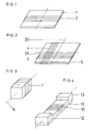
- FIG. 1 shows a flat magnetic core 1 with a winding 2, wherein the dimensions of the magnetic core may be, for example 20 x 10 x 0.2 cm.
- the base area of the core is preferably as large as the target area of a receiver to be covered. Due to the design of the winding, for example, a compression of the windings to the winding ends, a strong as possible homogeneous flux density over the core surface is generated.
- the special design of the flow orientation and the radiation characteristic shows the FIG. 2 a combination of two mutually perpendicular windings 3,4 on a running almost as a square plate magnetic core 5. The two windings can be alternately sequentially or simultaneously out of phase controlled against each other.
- the entire arrangement according to FIG. 1 or 2 be flexible. In any case, however, it is more resistant to breakage than, for example, an antenna with a ferrite core or a core made of another conventional material.
- FIG. 3 Particularly suitable for the transmission of energy to a moving receiver is the in FIG. 3 shown arrangement with a rod-shaped magnetic core, wherein the direction of movement, as well as the antenna of the receiver is directed parallel to the longitudinal axis 6 of the winding 7.
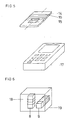
- FIG. 6 are two different magnetic cores 8, 9 shown, each having a separate winding and the longitudinal axes are perpendicular to each other to allow different flux densities and radiation characteristics.
- This is an alternative embodiment to that in the FIG. 2 shown with multiple windings on a single magnetic core.
- FIG. 4 shows an arrangement in which the winding 10 is integrated into a magnetic body 11 in so far as it passes through the magnetic core 11 itself, so that a lower part of the magnetic core 11 in the FIG. 4 forms a yoke that shorts the magnetic flux on the bottom.
- a shielding effect in one direction (down) is achieved with good radiation upwards.
- FIG. 5 shows in the magnetic core 14 has a recess 15, which allows there components of an electronic circuit, for example, to drive the winding 16 to accommodate.
- FIG. 6 shows an application example of the invention- ⁇ en antenna arrangement with a mobile communication terminal, such as a mobile phone or a cordless telephone 17, which has a non-illustrated receiving device for inductive coupling with the antenna assembly 18.
- the antenna arrangement 18 has in a housing 19, the two magnetic cores 8, 9, which are each provided with a winding and inductively can transmit energy to the receiver in the terminal 17.
- a capacitor or battery for storing the transmitted energy is provided in addition to the receiver.
- the same arrangement can also be used for retransmission of information, or a signal which is either also transmitted inductively, which would have to be switched between sending and receiving, or by evaluating the energy extraction of the receiver.
Landscapes
- Soft Magnetic Materials (AREA)
- Details Of Aerials (AREA)
- Near-Field Transmission Systems (AREA)
Description
Die Erfindung bezieht sich auf eine Antennenanordnung mit einem offenen Magnetkern und einer Wicklung.The invention relates to an antenna arrangement with an open magnetic core and a winding.
Die Erfindung liegt auf dem Gebiet der zur induktiven Energieübertragung genutzten Magnetfeldantennen. Grundsätzlich ist es möglich, Energie und Information mittels elektrischer oder magnetischer Dipole zu übertragen. Dabei werden je nach Ansteuerschaltung elektromagnetische Wellen oder auch nur überwiegend elektrische oder magnetische Felder erzeugt. Es kann wünschenswert sein, keine elektromagnetischen Wellen abzustrahlen, sondern sich auf die Erzeugung von magnetischen Feldern zu beschränken, um beispielsweise die Einwirkung auf organisches Gewebe im Umfeld der Antenne zu vermeiden. Insbesondere können durch die Abstrahlung von magnetischen Feldern beziehungsweise die induktive Kopplung an eine Magnetantenne verhältnismäßig hohe Energien ohne eine galvanische Kopplung übertragen werden. Die Wirkung einer solchen Kopplung ist auf einen engen räumlichen Bereich kleiner als etwa 1m begrenzt. Dennoch ergeben sich vielfältige Anwendungsmöglichkeiten für eine derartige Übertragung.The invention is in the field of magnetic field antennas used for inductive energy transmission. In principle, it is possible to transmit energy and information by means of electric or magnetic dipoles. Depending on the drive circuit, electromagnetic waves or only predominantly electrical or magnetic fields are generated. It may be desirable not to emit electromagnetic waves but to confine itself to the generation of magnetic fields, for example to avoid exposure to organic tissue around the antenna. In particular, by the emission of magnetic fields or the inductive coupling to a magnetic antenna relatively high energies can be transmitted without a galvanic coupling. The effect of such coupling is limited to a narrow spatial area less than about 1 meter. Nevertheless, there are many possible applications for such a transmission.
Im Prinzip können dabei neben gebräuchlichen Weichferriten die meisten bekannten weichmagnetischen Pulververbundwerkstoffe als gepresste Magnetkerne verwendet werden. Beispielsweise können diese aus Eisenpulver bestehen. Mit derartigen Magnetkernen lassen sich effektive Permeabilitäten zwischen ca. 10 und 30 erreichen. Entsprechend erreichbare Sättigungsinduktionen liegen bei ca. 1,0 bis 1,4 T. Es sind außerdem Pulververbundwerkstoffe aus weichmagnetischen kristallinen Eisen-Aluminium-Siliziumlegierungen und Eisen-Nickellegierungen bekannt, mit denen Anwendungsfrequenzen bis über 100 kHz erreicht werden können.In principle, in addition to customary soft ferrites, most known soft magnetic powder composite materials can be used as pressed magnetic cores. For example, these may consist of iron powder. With such magnetic cores, effective permeabilities between about 10 and 30 can be achieved. Correspondingly achievable saturation inductions are approximately 1.0 to 1.4 T. There are also powder composite materials of soft magnetic crystalline Iron-aluminum-silicon alloys and iron-nickel alloys are known, with which application frequencies can be achieved to over 100 kHz.
Der Nachteil von derartigen Verbundwerkstoffen und Ferriten besteht darin, dass die Presstechnologien nur einfache geometrische Formen zulassen und dass die entstehenden Magnetkerne relativ spröde und bruchgefährdet sind. Außerdem sind die entsprechenden Magneteigenschaften stark temperaturabhängig, was den Einsatz von Resonanzschwingkreisen erschwert.The disadvantage of such composites and ferrites is that the press technologies allow only simple geometric shapes and that the resulting magnetic cores are relatively brittle and vulnerable to breakage. In addition, the corresponding magnetic properties are strongly dependent on temperature, which makes the use of resonant circuits difficult.
Aus der
Entsprechende nanokristalline Legierungen sind beispielsweise aus der
Aus der
Dabei kommt es auf das ausfallsichere Funktionieren des Informationsaustausches in einem räumlichen Bereich von einigen Metern sowie die geringe Störanfälligkeit gegenüber metallischen Gegenständen im Umfeld der Antenne an.It depends on the fail-safe functioning of the information exchange in a spatial area of a few meters and the low susceptibility to interference with metallic objects in the vicinity of the antenna.
In
Der vorliegenden Erfindung liegt dagegen die Aufgabe zugrunde, eine Antennenanordnung zur Verwendung bei der induktiven Übertragung von Energie unabhängig von einer genauen Positionierung der Antennenanordnung gegenüber einem Empfänger bereitzustellen.On the other hand, the present invention is based on the object of providing an antenna arrangement for use in the inductive transmission of energy, regardless of a precise positioning of the antenna arrangement relative to a receiver.
Die vorliegende Erfindung zielt dabei auf die effektive Energieübertragung im Nahfeldbereich und das verlässliche Funktionieren unabhängig von einer genauen Positionierung der Antennenanordnung gegenüber einem Empfänger, zu dem hin die Energie auf induktivem Wege übertragen werden soll. Hierzu ist die Einstellung ganz bestimmter magnetischer Eigenschaften, insbesondere eines ausreichenden Flusses mit geeigneter Abstrahlungscharakteristik bei der Antennenanordnung notwendig.The present invention aims at the effective transmission of energy in the near field region and the reliable functioning independently of a precise positioning of the antenna arrangement relative to a receiver, to which the energy is to be transmitted by inductive means. For this purpose, the setting of very specific magnetic properties, in particular a sufficient flow with a suitable radiation characteristic in the antenna arrangement is necessary.
Es sollen mit Hilfe einer gattungsgemäßen Antennenanordnung Leistungen zwischen ca. 1 W und 100 W von einem Sender zu einem Empfänger über eine Entfernung zwischen etwa 0,5 und 50 cm übertragen werden. Anwendungsbeispiele hierzu sind alle Geräte, die drahtlos zeitweise oder dauernd mit Energie versorgt werden müssen. Dabei ist wegen der ausschließlich induktiven Kopplung ein Frequenzbereich von 10 khz bis 150 khz wegen der Verfügbarkeit dieses Frequenzbandes und den Dimensionierungsrandbedingungen besonders geeignet. Außerdem ist ein magnetischer Fluss von mindestens 20 Wb im Magnetkern zu verwirklichen.It should be using a generic antenna arrangement achievements between about 1 W and 100 W from a transmitter to a Receiver over a distance between about 0.5 and 50 cm are transmitted. Application examples for this are all devices that need to be supplied with power wirelessly, either temporarily or permanently. Because of the exclusively inductive coupling, a frequency range from 10 kHz to 150 kHz is particularly suitable because of the availability of this frequency band and the dimensioning boundary conditions. In addition, a magnetic flux of at least 20 Wb in the magnetic core can be realized.
Da derartige Antennen, wie sie in der vorliegenden Antennenanordnung eingesetzt werden, meistens den induktiven Teil eines Resonanzkreises darstellen, ist zur Optimierung der Energieabstrahlung eine hohe Antennengüte von mindestens 50, bevorzugt sogar 100 im Bereich der Arbeitsfrequenz wünschenswert. Außerdem ist eine temperaturunabhängige Permeabilität erforderlich, die zur optimalen Flussführung zwischen 30 und 200 liegt. Bei höherer Permeabilität ist die Flussbündelung im Kern so gut, dass seitlich ein zu geringer Flussanteil aus dem Kern austritt und die Feldstärke entlang des Kerns, das heisst im Empfängerbereich stark inhomogen wird.Since such antennas, as used in the present antenna arrangement, usually represent the inductive part of a resonant circuit, a high antenna quality of at least 50, preferably even 100 in the range of the operating frequency is desirable for optimizing the energy dissipation. In addition, a temperature-independent permeability is required, which is for optimal flow control between 30 and 200. With higher permeability, the flux bundling in the core is so good that laterally too low a flow component emerges from the core and the field strength along the core, ie in the receiver region, becomes highly inhomogeneous.
Die Aufgabe, die der vorliegenden Erfindung zu Grunde liegt, kann mit den bekannten Magnetanordnungen, Magnetkernen und Werkstoffen nicht befriedigend gelöst werden.The object underlying the present invention can not be solved satisfactorily with the known magnet arrangements, magnetic cores and materials.
Sie wird erfindungsgemäß durch eine Anordnung gemäß Anspruch ein Verfahrenzum Betrieb 1 sowie einer solchen Anordnung gemäß Anspruch 11 gelöst. Ausgestaltungen und Weiterbildungen des Erfindungsgedankene sind Gegenstand von Unteransprtichen.It is inventively achieved by an arrangement according to claim a method for
Erfindungsgemäß enthält der Magnetkern als Verbundwerkstoff eine weichmagnetische Komponente aus feinverteilten Partikeln und eine Kunststoffkomponente, wobei der Magnetkern eine Anfangspermeabilität zwischen 20 und 200 sowie eine Sättigungsinduktion > 0,6 T aufweist.According to the invention, the magnetic core contains as a composite material a soft magnetic component of finely divided particles and a plastic component, wherein the magnetic core has an initial permeability between 20 and 200 and a saturation induction> 0.6 T.
Die weichmagnetische Komponente besteht vorteilhaft aus den bereits erwähnten Flakes aus einem nanokristallinen Material. Dieses weist eine Sättigungsmagnetisierung von ca. 1 bis 1,6T und Permeabilitäten > 30.000 auf. Durch die Vermischung mit einer Kunststoffkomponente wird der magnetische Kreis durch die mikroskopischen Lücken zwischen den Flakes unterbrochen und es lassen sich niedrigere effektive Permeabilitäten von 30 bis 100 bei hoher Güte und Temperaturkonstanz einstellen. Dennoch ergibt sich eine hohe erreichbare Flussdichte größer als 0,6 T, typisch auch größer als 0,9 T. Die weichmagnetische Komponente des Magnetkernes hat außerdem vorteilhaft die Eigenschaft, dass die Partikel jeweils einzeln durch eine Oberflächenschicht elektrisch isoliert sind. Diese kann beispielsweise durch Oberflächenoxidation oder Kunststoffbeschichtung realisiert sein. Die Partikelgröße kann vorteilhaft weniger als 2mm betragen, wobei die Partikeldicken kleiner als 0,5mm sein können. Durch diese Ausgestaltung der Partikel werden besonders geringe Ummagnetisierungsverluste und damit eine besonders hohe Güte der Antenne erreicht.Die mechanischen Eigenschaften sind je nach der Art und Anteil des eingesetzten Kunststoffes bezüglich der Bruchzähigkeit und Biegsamkeit sowie deren Temperaturabhängigkeit einstellbar.The soft magnetic component advantageously consists of the already mentioned flakes of a nanocrystalline material. This has a saturation magnetization of about 1 to 1.6T and permeabilities> 30,000. By mixing with a plastic component of the magnetic circuit is through the microscopic gaps between the flakes are interrupted and it is possible to set lower effective permeabilities of 30 to 100 with high quality and temperature stability. Nevertheless, a high achievable flux density greater than 0.6 T, typically greater than 0.9 T. The soft magnetic component of the magnetic core also has the advantageous advantage that the particles are each electrically isolated by a surface layer. This can be realized for example by surface oxidation or plastic coating. The particle size may advantageously be less than 2 mm, wherein the particle thicknesses may be smaller than 0.5 mm. As a result of this configuration of the particles, particularly low loss of magnetization losses and thus a particularly high quality of the antenna are achieved. The mechanical properties can be adjusted with regard to the type and proportion of the plastic used with regard to fracture toughness and flexibility as well as their temperature dependence.
Als Kunststoffkomponente können generell alle im Rahmen der Gießharztechnologie verarbeitbaren Thermo- oder Duroplaste wie Polyamid, Polyacrylat, Polyacetat, Polyimid oder Epoxidharz je nach den gewünschten mechanischen und thermischen Eigenschaften gewählt werden.As a plastic component can generally be used in the context of cast resin technology thermosets or thermosets such as polyamide, polyacrylate, polyacetate, polyimide or epoxy resin depending on the desired mechanical and thermal properties.
Im einfachsten Fall weist die Antennenanordnung als Magnetkern einen Stab oder eine Platte auf, die mit einer Bewicklung versehen sind. Es sind bestimmte Kernquerschnitte notwendig, um die Anordnung für die effektive Übertragung von Energie einsetzbar zu machen. Soll im Kern ein mittlerer Fluss von mindestens 20 µWb erreicht werden, so ergibt sich eine Induktion von 400 mT bei einem Querschnitt von 0,5 cm2. Dies entspricht etwa der Hälfte des Querschnittes, der bei Einsatz eines Weichferrites notwendig wäre.In the simplest case, the antenna arrangement as a magnetic core on a rod or a plate, which are provided with a winding. Certain core cross-sections are necessary to make the arrangement usable for the effective transmission of energy. If an average flux of at least 20 μWb is to be achieved in the core, this results in an induction of 400 mT with a cross section of 0.5 cm 2 . This corresponds to about half of the cross section, which would be necessary when using a soft ferrite.
Dabei sollte, um den Magnetkern zur Erhöhung des Flusses effektiv nutzen zu können, die Spulenlänge der Wicklung größer sein als ihr Durchmesser, vorzugsweise groß gegenüber dem Durchmesser. Eine wesentliche Eigenschaft des erfindungsgemäß eingesetzten Materials ist die mechanische Unempfindlichkeit gegen Stoß oder Vibrationen und die freie Formgebung im Rahmen der Herstellung beziehungsweise eine nachträgliche Biegsamkeit. Das erfindungsgemäß eingesetzte Material erlaubt wegen seiner magnetischen Eigenschaften außerdem eine kleine Baugröße, wie sie aus Kosten-, Platz- und Designgründen in vielen Anwendungsbereichen wünschenswert ist.In this case, in order to use the magnetic core to increase the flow effectively, the coil length of the winding should be greater than its diameter, preferably large compared to the diameter. An essential feature of the material used according to the invention is the mechanical insensitivity to shock or vibration and the free shaping during the production or a subsequent flexibility. The inventively used material also allows because of its magnetic properties also a small size, as it is desirable for cost, space and design reasons in many applications.
Zur Realisierung der gewünschten Abstrahlcharakteristik beziehungsweise Flussführung der Antennenanordnung kann es vorteilhaft sein, dass mehrere Wicklungen auf demselben Magnetkern angeordnet sind, wobei die Längsachsen der Wicklungen in einem Winkel > 0°, beispielsweise 90° zueinander stehen. Die Wicklungen können gleichzeitig, phasenversetzt oder abwechselnd angesteuert werden, um Empfänger der induktiven Energieübertragung in verschiedenen Positionen zu erreichen. Dadurch wird die Energieübertragung zuverlässiger und bezüglich der relativen Positionierung von Sender und Empfänger unempfindlicher. Die Erfindung bezieht sich dabei auch auf verschiedene Betriebsverfahren der erfindungsgemäßen Antennenanordnung mit intermittierendem Betrieb der verschiedenen Wicklungen beziehungsweise dem erwähnten phasenverschobenen gleichzeitigen Ansteuern der unterschiedlichen Wicklungen.To realize the desired radiation characteristic or flux guidance of the antenna arrangement, it may be advantageous for a plurality of windings to be arranged on the same magnetic core, wherein the longitudinal axes of the windings are at an angle> 0 °, for example 90 ° to each other. The windings may be driven simultaneously, out of phase or alternately to reach inductive energy transfer receivers in different positions. This makes the transmission of energy more reliable and less sensitive to the relative positioning of transmitter and receiver. The invention also relates to various operating methods of the antenna arrangement according to the invention with intermittent operation of the various windings or the mentioned phase-shifted simultaneous driving of the different windings.
Zur Erreichung einer derartigen vergrößerten Akzeptanz bei der Positionierung von Sender und Empfänger ist es auch denkbar, dass mehrere Wicklungen auf verschiedenen Magnetkernen der genannten Art vorgesehen werden, wobei die Abstrahlcharakteristik der einzelnen Magnetkerne unterschiedlich geformt oder ausgerichtet ist. Auch durch diese Maßnahme wird der optimale Positionierbereich eines Empfängers der ausgesandten Energie vergrößert.In order to achieve such increased acceptance in the positioning of transmitter and receiver, it is also conceivable that a plurality of windings are provided on different magnetic cores of the type mentioned, wherein the emission characteristic of the individual magnetic cores is differently shaped or aligned. Also by this measure, the optimum positioning range of a receiver of the emitted energy is increased.
Da die erfindungsgemäße Antennenanordnung auch darauf ausgerichtet ist, platzsparend zu sein, kann es zusätzlich sinnvoll sein, eine Ausnehmung innerhalb eines Magnetkerns vorzusehen, in der elektronische Komponenten, beispielsweise der Ansteuerschaltung der Antennenanordnung, untergebracht werden können. Die Flussführung innerhalb des Magnetkerns wird durch derartige Ausnehmungen, wenn sie nicht zu groß sind, kaum negativ beeinflusst. Außerdem kann die Antennenanordnung mit der Ansteuerschaltung vorteilhaft vorgefertigt und als integrale Baueinheit einfach in ein Gerät eingesetzt werden.Since the antenna arrangement according to the invention is also designed to save space, it may additionally be useful to provide a recess within a magnetic core in which electronic components, for example the drive circuit of the antenna arrangement, can be accommodated. The flow guidance within the magnetic core is hardly negatively influenced by such recesses, if they are not too large. In addition, the antenna arrangement can advantageously be prefabricated with the drive circuit and simply used as an integral unit in a device.
Die Erfindung wird nachfolgend anhand der in den Figuren der Zeichnung dargestellten Ausführungsbeispiele näher erläutert. Es zeigt:
Figur 1- eine plattenförmige rechteckige Gestaltung eines Magnetkerns mit einer Wicklung,
Figur 2- einen entsprechenden Magnetkern mit zwei Wicklungen,
Figur 3- einen stabförmigen Magnetkern mit einer Wicklung,
Figur 4- einen stabförmigen Magnetkern mit einer integrierten Wicklung und Polschuhen,
Figur 5- einen Magnetkern mit einer Ausnehmung und
Figur 6- eine Anwendung der Antennenanordnung mit zwei Magnetkernen.
- FIG. 1
- a plate-shaped rectangular design of a magnetic core with a winding,
- FIG. 2
- a corresponding magnetic core with two windings,
- FIG. 3
- a rod-shaped magnetic core with a winding,
- FIG. 4
- a rod-shaped magnetic core with an integrated winding and pole shoes,
- FIG. 5
- a magnetic core with a recess and
- FIG. 6
- an application of the antenna arrangement with two magnetic cores.
Bei geeigneter Wahl der Kunststoffkomponente kann die gesamte Anordnung gemäß
Besonders geeignet für die Übermittlung von Energie zu einem bewegten Empfänger ist die in
In der
Die
Zur Herstellung einer derartigen Anordnung ist das in der
Die
Die
Trotz der Spezialisierung der beschriebenen Antennenanordnung auf die Energieübertragung, kann die selbe Anordnung auch zur Rückübertragung einer Information, beziehungsweise eines Signals dienen, das entweder ebenfalls induktiv übermittelt wird, wobei zwischen Senden und Empfangen umgeschaltet werden müsste, oder durch Auswertung der Energieentnahme des Empfängers.Despite the specialization of the described antenna arrangement on the energy transfer, the same arrangement can also be used for retransmission of information, or a signal which is either also transmitted inductively, which would have to be switched between sending and receiving, or by evaluating the energy extraction of the receiver.
Es ist auch die Anwendung der Erfindung bei der Übertragung von Energie von einem mobilen Gerät zu einem stationären Gerät denkbar, beispielsweise in der Bahntechnik zur Übertragung von Signalen und/oder Energie von einem an einem Fahrzeug befestigten Gerät zu einem stationären Sensor einer Leitwarte/eines Stellwerkes zur Verkehrsüberwachung.It is also the application of the invention in the transmission of energy from a mobile device to a stationary device conceivable, for example in railway technology for transmitting signals and / or energy from a device attached to a vehicle to a stationary sensor of a control room / a signal box for traffic monitoring.
Claims (11)
- An antenna arrangement, comprising a magnetic core (1, 5, 14) and at least one winding (2, 3, 4, 7, 10, 16), by way of which inductive energy is transferred from a transmitter to a receiver over a distance between approximately 0.5 and 50 cm,
characterized in that
the magnetic core (1, 5, 14) contains composite material, which comprises a soft magnetic component mixed with a plastic component, wherein the soft magnetic component comprises finely distributed particles made of nanocrystalline material having a saturation magnetization of 1 to 1.6 Tesla and permeabilities of greater than 30,000, such that the magnetic core (1, 5, 14) has an effective initial permeability of between 20 and 200 and a saturation induction of greater than 0.6 Tesla, and the magnetic core (1, 5, 14) has a magnetic flux loading capacity of up to at least 20 µWb. - The antenna arrangement according to claim 1, in which the soft magnetic component consists of particles that are individually electrically insulated by a surface layer.
- The antenna arrangement according to claim 1 or 2, in which the particle size is less than 2 mm.
- The antenna arrangement according to claim 1, 2 or 3, in which the particle thicknesses are less than 0.5 mm.
- An antenna arrangement according to one of claims 2 to 4, in which the particles are surface-oxidized or plastic-coated.
- An antenna arrangement according to one of claims 1 to 5, in which the plastic component contains a thermoplastic or duroplastic, which can be processed within the scope of casting resin technology.
- An antenna arrangement according to one of claims 1 to 6, in which the antenna formed by the magnetic core (1, 5, 14) and the winding(s) (2, 3, 4, 7, 10, 16) has a quality of more than 50 in the frequency range between 20 kHz and 150 kHz.
- An antenna arrangement according to one of claims 1 to 7, comprising a plurality of windings (2, 3, 4, 7, 10, 16) on the same magnetic core (1, 5, 14), wherein the longitudinal axes (20, 21) of the windings are disposed relative to one another at an angle of more than 0°.
- The antenna arrangement according to claim 8, in which a plurality of magnetic cores (1, 5, 14) support the windings (2, 3, 4, 7, 10, 16).
- An antenna arrangement according to one of claims 1 to 9, in which a cut-out (15) for receiving electronic components is provided in at least one of the magnetic cores (1, 5, 14).
- A method for operating an antenna arrangement according to claims 1 to 10,
characterized in that
in the antenna arrangement, the various windings (2, 3, 4, 7, 10, 16) are actuated simultaneously with phase shift or in a chronologically alternating manner.
Applications Claiming Priority (2)
| Application Number | Priority Date | Filing Date | Title |
|---|---|---|---|
| DE102004023815A DE102004023815A1 (en) | 2004-05-13 | 2004-05-13 | Antenna arrangement and use of the antenna arrangement |
| PCT/EP2005/005271 WO2005112192A1 (en) | 2004-05-13 | 2005-05-13 | Antenna arrangement for inductive energy transmission and use of the antenna arrangement |
Publications (2)
| Publication Number | Publication Date |
|---|---|
| EP1745527A1 EP1745527A1 (en) | 2007-01-24 |
| EP1745527B1 true EP1745527B1 (en) | 2013-04-17 |
Family
ID=34967320
Family Applications (1)
| Application Number | Title | Priority Date | Filing Date |
|---|---|---|---|
| EP05741826.1A Expired - Lifetime EP1745527B1 (en) | 2004-05-13 | 2005-05-13 | Antenna arrangement for inductive energy transmission and use of the antenna arrangement |
Country Status (5)
| Country | Link |
|---|---|
| US (1) | US7545337B2 (en) |
| EP (1) | EP1745527B1 (en) |
| JP (1) | JP2007537637A (en) |
| DE (1) | DE102004023815A1 (en) |
| WO (1) | WO2005112192A1 (en) |
Families Citing this family (102)
| Publication number | Priority date | Publication date | Assignee | Title |
|---|---|---|---|---|
| DE102004023815A1 (en) | 2004-05-13 | 2005-12-08 | Vacuumschmelze Gmbh & Co. Kg | Antenna arrangement and use of the antenna arrangement |
| CN102983639B (en) | 2005-07-12 | 2016-01-27 | 麻省理工学院 | Wireless non-radiative energy transmits |
| US7825543B2 (en) | 2005-07-12 | 2010-11-02 | Massachusetts Institute Of Technology | Wireless energy transfer |
| US20070115192A1 (en) * | 2005-11-18 | 2007-05-24 | Omron Automotive Electronics, Inc. | Key fob having LF single dimension tranceive antenna and two-dimension receive antenna |
| US8447234B2 (en) | 2006-01-18 | 2013-05-21 | Qualcomm Incorporated | Method and system for powering an electronic device via a wireless link |
| US9130602B2 (en) | 2006-01-18 | 2015-09-08 | Qualcomm Incorporated | Method and apparatus for delivering energy to an electrical or electronic device via a wireless link |
| GB2440571A (en) * | 2006-08-01 | 2008-02-06 | Splashpower Ltd | Drive for an inductive coupling with a changing magnetic field direction |
| US9774086B2 (en) | 2007-03-02 | 2017-09-26 | Qualcomm Incorporated | Wireless power apparatus and methods |
| US9421388B2 (en) | 2007-06-01 | 2016-08-23 | Witricity Corporation | Power generation for implantable devices |
| US8115448B2 (en) | 2007-06-01 | 2012-02-14 | Michael Sasha John | Systems and methods for wireless power |
| US9124120B2 (en) | 2007-06-11 | 2015-09-01 | Qualcomm Incorporated | Wireless power system and proximity effects |
| US7825869B2 (en) * | 2007-07-03 | 2010-11-02 | Masin Joseph V | Miniature transponders |
| CN101842962B (en) | 2007-08-09 | 2014-10-08 | 高通股份有限公司 | Increasing the Q factor of a resonator |
| CN101803109A (en) | 2007-09-13 | 2010-08-11 | 高通股份有限公司 | Maximizing power yield from wireless power magnetic resonators |
| EP2201641A1 (en) | 2007-09-17 | 2010-06-30 | Qualcomm Incorporated | Transmitters and receivers for wireless energy transfer |
| KR101606664B1 (en) | 2007-10-11 | 2016-03-25 | 퀄컴 인코포레이티드 | Wireless power transfer using magneto mechanical systems |
| US8629576B2 (en) | 2008-03-28 | 2014-01-14 | Qualcomm Incorporated | Tuning and gain control in electro-magnetic power systems |
| US9246336B2 (en) | 2008-09-27 | 2016-01-26 | Witricity Corporation | Resonator optimizations for wireless energy transfer |
| US8963488B2 (en) | 2008-09-27 | 2015-02-24 | Witricity Corporation | Position insensitive wireless charging |
| US8947186B2 (en) | 2008-09-27 | 2015-02-03 | Witricity Corporation | Wireless energy transfer resonator thermal management |
| US8901779B2 (en) | 2008-09-27 | 2014-12-02 | Witricity Corporation | Wireless energy transfer with resonator arrays for medical applications |
| US9515494B2 (en) | 2008-09-27 | 2016-12-06 | Witricity Corporation | Wireless power system including impedance matching network |
| US8772973B2 (en) | 2008-09-27 | 2014-07-08 | Witricity Corporation | Integrated resonator-shield structures |
| US8922066B2 (en) | 2008-09-27 | 2014-12-30 | Witricity Corporation | Wireless energy transfer with multi resonator arrays for vehicle applications |
| US8643326B2 (en) | 2008-09-27 | 2014-02-04 | Witricity Corporation | Tunable wireless energy transfer systems |
| US8598743B2 (en) | 2008-09-27 | 2013-12-03 | Witricity Corporation | Resonator arrays for wireless energy transfer |
| US8957549B2 (en) | 2008-09-27 | 2015-02-17 | Witricity Corporation | Tunable wireless energy transfer for in-vehicle applications |
| US9105959B2 (en) | 2008-09-27 | 2015-08-11 | Witricity Corporation | Resonator enclosure |
| US8912687B2 (en) | 2008-09-27 | 2014-12-16 | Witricity Corporation | Secure wireless energy transfer for vehicle applications |
| US9601266B2 (en) | 2008-09-27 | 2017-03-21 | Witricity Corporation | Multiple connected resonators with a single electronic circuit |
| US8692412B2 (en) | 2008-09-27 | 2014-04-08 | Witricity Corporation | Temperature compensation in a wireless transfer system |
| US9744858B2 (en) | 2008-09-27 | 2017-08-29 | Witricity Corporation | System for wireless energy distribution in a vehicle |
| US8946938B2 (en) | 2008-09-27 | 2015-02-03 | Witricity Corporation | Safety systems for wireless energy transfer in vehicle applications |
| US9577436B2 (en) | 2008-09-27 | 2017-02-21 | Witricity Corporation | Wireless energy transfer for implantable devices |
| US8669676B2 (en) | 2008-09-27 | 2014-03-11 | Witricity Corporation | Wireless energy transfer across variable distances using field shaping with magnetic materials to improve the coupling factor |
| US8482158B2 (en) | 2008-09-27 | 2013-07-09 | Witricity Corporation | Wireless energy transfer using variable size resonators and system monitoring |
| US9601270B2 (en) | 2008-09-27 | 2017-03-21 | Witricity Corporation | Low AC resistance conductor designs |
| US8901778B2 (en) | 2008-09-27 | 2014-12-02 | Witricity Corporation | Wireless energy transfer with variable size resonators for implanted medical devices |
| US8497601B2 (en) | 2008-09-27 | 2013-07-30 | Witricity Corporation | Wireless energy transfer converters |
| US9160203B2 (en) | 2008-09-27 | 2015-10-13 | Witricity Corporation | Wireless powered television |
| US8933594B2 (en) | 2008-09-27 | 2015-01-13 | Witricity Corporation | Wireless energy transfer for vehicles |
| US9396867B2 (en) | 2008-09-27 | 2016-07-19 | Witricity Corporation | Integrated resonator-shield structures |
| US20100259110A1 (en) * | 2008-09-27 | 2010-10-14 | Kurs Andre B | Resonator optimizations for wireless energy transfer |
| US8723366B2 (en) | 2008-09-27 | 2014-05-13 | Witricity Corporation | Wireless energy transfer resonator enclosures |
| US9035499B2 (en) | 2008-09-27 | 2015-05-19 | Witricity Corporation | Wireless energy transfer for photovoltaic panels |
| US9065423B2 (en) | 2008-09-27 | 2015-06-23 | Witricity Corporation | Wireless energy distribution system |
| US8928276B2 (en) | 2008-09-27 | 2015-01-06 | Witricity Corporation | Integrated repeaters for cell phone applications |
| US8937408B2 (en) | 2008-09-27 | 2015-01-20 | Witricity Corporation | Wireless energy transfer for medical applications |
| US9601261B2 (en) * | 2008-09-27 | 2017-03-21 | Witricity Corporation | Wireless energy transfer using repeater resonators |
| US20120091949A1 (en) * | 2008-09-27 | 2012-04-19 | Campanella Andrew J | Wireless energy transfer for energizing power tools |
| JP2012504387A (en) * | 2008-09-27 | 2012-02-16 | ウィトリシティ コーポレーション | Wireless energy transfer system |
| US9544683B2 (en) | 2008-09-27 | 2017-01-10 | Witricity Corporation | Wirelessly powered audio devices |
| US9184595B2 (en) | 2008-09-27 | 2015-11-10 | Witricity Corporation | Wireless energy transfer in lossy environments |
| US9318922B2 (en) | 2008-09-27 | 2016-04-19 | Witricity Corporation | Mechanically removable wireless power vehicle seat assembly |
| US9093853B2 (en) | 2008-09-27 | 2015-07-28 | Witricity Corporation | Flexible resonator attachment |
| US9106203B2 (en) | 2008-09-27 | 2015-08-11 | Witricity Corporation | Secure wireless energy transfer in medical applications |
| US8907531B2 (en) | 2008-09-27 | 2014-12-09 | Witricity Corporation | Wireless energy transfer with variable size resonators for medical applications |
| US8362651B2 (en) | 2008-10-01 | 2013-01-29 | Massachusetts Institute Of Technology | Efficient near-field wireless energy transfer using adiabatic system variations |
| US9008574B2 (en) * | 2009-09-14 | 2015-04-14 | Qualcomm Incorporated | Focused antenna, multi-purpose antenna, and methods related thereto |
| US9602168B2 (en) | 2010-08-31 | 2017-03-21 | Witricity Corporation | Communication in wireless energy transfer systems |
| US9948145B2 (en) | 2011-07-08 | 2018-04-17 | Witricity Corporation | Wireless power transfer for a seat-vest-helmet system |
| CN108110907B (en) | 2011-08-04 | 2022-08-02 | 韦特里西提公司 | Tunable wireless power supply architecture |
| KR102010943B1 (en) | 2011-09-09 | 2019-08-14 | 위트리시티 코포레이션 | Foreign object detection in wireless energy transfer systems |
| US20130062966A1 (en) | 2011-09-12 | 2013-03-14 | Witricity Corporation | Reconfigurable control architectures and algorithms for electric vehicle wireless energy transfer systems |
| US9318257B2 (en) | 2011-10-18 | 2016-04-19 | Witricity Corporation | Wireless energy transfer for packaging |
| HK1200602A1 (en) | 2011-11-04 | 2015-08-07 | WiTricity公司 | Wireless energy transfer modeling tool |
| EP2807720A4 (en) | 2012-01-26 | 2015-12-02 | Witricity Corp | TRANSFER OF WIRELESS ENERGY WITH REDUCED FIELDS |
| JP5639606B2 (en) * | 2012-02-27 | 2014-12-10 | 三智商事株式会社 | Wireless IC tag |
| US8929810B2 (en) | 2012-04-23 | 2015-01-06 | Qualcomm Incorporated | Methods and apparatus for improving NFC connection through device positioning |
| US9343922B2 (en) | 2012-06-27 | 2016-05-17 | Witricity Corporation | Wireless energy transfer for rechargeable batteries |
| US9287607B2 (en) | 2012-07-31 | 2016-03-15 | Witricity Corporation | Resonator fine tuning |
| US9595378B2 (en) | 2012-09-19 | 2017-03-14 | Witricity Corporation | Resonator enclosure |
| US9465064B2 (en) | 2012-10-19 | 2016-10-11 | Witricity Corporation | Foreign object detection in wireless energy transfer systems |
| US9449757B2 (en) | 2012-11-16 | 2016-09-20 | Witricity Corporation | Systems and methods for wireless power system with improved performance and/or ease of use |
| DE102013104059B8 (en) * | 2013-04-22 | 2024-09-19 | Infineon Technologies Ag | Antenna arrangement and communication device |
| US9601267B2 (en) | 2013-07-03 | 2017-03-21 | Qualcomm Incorporated | Wireless power transmitter with a plurality of magnetic oscillators |
| JP2016534698A (en) | 2013-08-14 | 2016-11-04 | ワイトリシティ コーポレーションWitricity Corporation | Impedance tuning |
| DE102013113244A1 (en) * | 2013-11-29 | 2015-06-03 | Paul Vahle Gmbh & Co. Kg | Coil for an inductive energy transfer system |
| US9780573B2 (en) | 2014-02-03 | 2017-10-03 | Witricity Corporation | Wirelessly charged battery system |
| WO2015123614A2 (en) | 2014-02-14 | 2015-08-20 | Witricity Corporation | Object detection for wireless energy transfer systems |
| US9892849B2 (en) | 2014-04-17 | 2018-02-13 | Witricity Corporation | Wireless power transfer systems with shield openings |
| US9842687B2 (en) | 2014-04-17 | 2017-12-12 | Witricity Corporation | Wireless power transfer systems with shaped magnetic components |
| US9837860B2 (en) | 2014-05-05 | 2017-12-05 | Witricity Corporation | Wireless power transmission systems for elevators |
| CN106489082B (en) | 2014-05-07 | 2021-09-21 | 无线电力公司 | Foreign object detection in wireless energy transfer systems |
| US9954375B2 (en) | 2014-06-20 | 2018-04-24 | Witricity Corporation | Wireless power transfer systems for surfaces |
| US9842688B2 (en) | 2014-07-08 | 2017-12-12 | Witricity Corporation | Resonator balancing in wireless power transfer systems |
| US10574091B2 (en) | 2014-07-08 | 2020-02-25 | Witricity Corporation | Enclosures for high power wireless power transfer systems |
| US9843217B2 (en) | 2015-01-05 | 2017-12-12 | Witricity Corporation | Wireless energy transfer for wearables |
| US10461396B2 (en) * | 2015-04-03 | 2019-10-29 | Fit Pay, Inc. | System and method for low-power close-proximity communications and energy transfer using a miniature multi-purpose antenna |
| DE102015111038B4 (en) * | 2015-07-08 | 2021-05-06 | Infineon Technologies Ag | A vertical ferrite antenna with prefabricated connection components |
| WO2017062647A1 (en) | 2015-10-06 | 2017-04-13 | Witricity Corporation | Rfid tag and transponder detection in wireless energy transfer systems |
| JP2018538517A (en) | 2015-10-14 | 2018-12-27 | ワイトリシティ コーポレーションWitricity Corporation | Phase and amplitude detection in wireless energy transfer systems |
| WO2017070227A1 (en) | 2015-10-19 | 2017-04-27 | Witricity Corporation | Foreign object detection in wireless energy transfer systems |
| CN108781002B (en) | 2015-10-22 | 2021-07-06 | 韦特里西提公司 | Dynamic Tuning in Wireless Energy Transfer Systems |
| US10075019B2 (en) | 2015-11-20 | 2018-09-11 | Witricity Corporation | Voltage source isolation in wireless power transfer systems |
| CN109075613B (en) | 2016-02-02 | 2022-05-31 | 韦特里西提公司 | Controlling a wireless power transfer system |
| WO2017139406A1 (en) | 2016-02-08 | 2017-08-17 | Witricity Corporation | Pwm capacitor control |
| EP3400628B1 (en) | 2016-02-11 | 2022-06-01 | Samsung Electronics Co., Ltd. | Electronic device having loop antenna |
| US20180123227A1 (en) * | 2016-10-31 | 2018-05-03 | Hoi Luen Electrical Manufacturer Company Limited | Power Transmitting Antenna and Method of Production |
| EP3646434B1 (en) | 2017-06-29 | 2025-01-22 | Witricity Corporation | Protection and control of wireless power systems |
| US12009672B2 (en) | 2018-06-29 | 2024-06-11 | Brusa Elektronik Ag | Devices for the contactless inductive charging of an electrical energy store |
| BE1028203B1 (en) | 2020-04-09 | 2021-11-08 | Phoenix Contact Gmbh & Co | Coupling device for wireless data and energy transmission and a coupling system for wireless data and energy transmission |
Citations (1)
| Publication number | Priority date | Publication date | Assignee | Title |
|---|---|---|---|---|
| DE19718423A1 (en) * | 1997-04-30 | 1998-11-05 | Siemens Ag | Portable signal receiver |
Family Cites Families (14)
| Publication number | Priority date | Publication date | Assignee | Title |
|---|---|---|---|---|
| US3949388A (en) * | 1972-11-13 | 1976-04-06 | Monitron Industries, Inc. | Physiological sensor and transmitter |
| US4881989A (en) | 1986-12-15 | 1989-11-21 | Hitachi Metals, Ltd. | Fe-base soft magnetic alloy and method of producing same |
| CA2040741C (en) * | 1990-04-24 | 2000-02-08 | Kiyonori Suzuki | Fe based soft magnetic alloy, magnetic materials containing same, and magnetic apparatus using the magnetic materials |
| KR100459839B1 (en) | 1995-08-22 | 2005-02-07 | 미쓰비시 마테리알 가부시키가이샤 | Antennas and transponders for transponders |
| DE19846781C2 (en) | 1998-10-10 | 2000-07-20 | Ald Vacuum Techn Ag | Method and device for producing precision castings by centrifugal casting |
| JP3975627B2 (en) * | 1998-12-31 | 2007-09-12 | カシオ計算機株式会社 | Data communication device |
| DE10024824A1 (en) * | 2000-05-19 | 2001-11-29 | Vacuumschmelze Gmbh | Inductive component and method for its production |
| AU2001288726A1 (en) * | 2000-09-02 | 2002-03-22 | Em-Tech Llc | Measurements of electrical properties through non magnetically permeable metals using directed magnetic beams and magnetic lenses |
| JP2002280224A (en) * | 2001-01-05 | 2002-09-27 | Humanelecs Co Ltd | Amorphous alloy powder core and nanocrystal alloy powder core, and their manufacturing method |
| DE10128004A1 (en) | 2001-06-08 | 2002-12-19 | Vacuumschmelze Gmbh | Wound inductive device has soft magnetic core of ferromagnetic powder composite of amorphous or nanocrystalline ferromagnetic alloy powder, ferromagnetic dielectric powder and polymer |
| US6654698B2 (en) | 2001-06-12 | 2003-11-25 | Applied Materials, Inc. | Systems and methods for calibrating integrated inspection tools |
| US6906495B2 (en) * | 2002-05-13 | 2005-06-14 | Splashpower Limited | Contact-less power transfer |
| EP1496568A1 (en) * | 2003-07-05 | 2005-01-12 | Kaschke KG GmbH & Co. | Transponder coil for wireless vehicle key entry systems |
| DE102004023815A1 (en) | 2004-05-13 | 2005-12-08 | Vacuumschmelze Gmbh & Co. Kg | Antenna arrangement and use of the antenna arrangement |
-
2004
- 2004-05-13 DE DE102004023815A patent/DE102004023815A1/en not_active Ceased
-
2005
- 2005-05-13 JP JP2007512117A patent/JP2007537637A/en active Pending
- 2005-05-13 EP EP05741826.1A patent/EP1745527B1/en not_active Expired - Lifetime
- 2005-05-13 WO PCT/EP2005/005271 patent/WO2005112192A1/en not_active Ceased
-
2006
- 2006-11-13 US US11/559,171 patent/US7545337B2/en not_active Expired - Fee Related
Patent Citations (1)
| Publication number | Priority date | Publication date | Assignee | Title |
|---|---|---|---|---|
| DE19718423A1 (en) * | 1997-04-30 | 1998-11-05 | Siemens Ag | Portable signal receiver |
Also Published As
| Publication number | Publication date |
|---|---|
| US7545337B2 (en) | 2009-06-09 |
| JP2007537637A (en) | 2007-12-20 |
| WO2005112192A9 (en) | 2006-02-09 |
| US20070126650A1 (en) | 2007-06-07 |
| DE102004023815A1 (en) | 2005-12-08 |
| WO2005112192A1 (en) | 2005-11-24 |
| EP1745527A1 (en) | 2007-01-24 |
Similar Documents
| Publication | Publication Date | Title |
|---|---|---|
| EP1745527B1 (en) | Antenna arrangement for inductive energy transmission and use of the antenna arrangement | |
| EP3427339B1 (en) | Antenna | |
| KR101923570B1 (en) | Flexible soft magnetic core, antenna with flexible soft magnetic core and method for producing a flexible soft magnetic core | |
| DE102006027829A1 (en) | Coil for resonant antenna used in card type wireless device, has several unit coils, each of which has same winding direction and same number of turns and unit coils are connected in parallel to each other | |
| DE112007000799T5 (en) | Wireless IC device | |
| WO2009033847A2 (en) | Sensor arrangement and method for operating a sensor arrangement | |
| EP3579336A1 (en) | Antenna and device incorporating the same | |
| WO2014096039A1 (en) | Inductive charging coil device | |
| EP2068330A3 (en) | Inductive device including permanent magnet and associated methods | |
| EP2941861B1 (en) | Housing wall | |
| DE102006022354A1 (en) | A wireless card-type device, antenna coil, and method of fabricating a communication module | |
| EP2529338B1 (en) | Portable data carrier having a radio-based data communication device | |
| DE102006024247A1 (en) | Antenna coil for communication module, has flat coil body whose thickness is in coil body axial direction, where coil carrier construction unit is arranged between substrate and coil body, which is carried on substrate surface | |
| DE102021201095A1 (en) | Space-saving antenna for a hearing instrument | |
| EP3036793B1 (en) | Device and method for combined signal transmission or for combined signal transmission and energy transmission | |
| DE102007008575B4 (en) | Antenna device with ion-implanted resonance structure | |
| DE202019103465U1 (en) | NF-emitter antenna | |
| WO2012019694A1 (en) | Portable data carrier having a data communication device that operates by means of a coil coupling | |
| DE102016121335B4 (en) | Magnetic antenna with reduced losses and use thereof | |
| DE102009023374A1 (en) | antenna device | |
| EP4104458A1 (en) | Space-saving magnetic induction antenna for a hearing aid | |
| DE102011087928B4 (en) | METALLIC CARRIER BODY WITH TRANSPONDER | |
| DE102009023373B4 (en) | Antenna device | |
| PL202423B1 (en) | Method for manufacture of the magnetic core from powder composites and the magnetic core made of powder composites | |
| DE102006004000A1 (en) | Antenna for motor vehicle door, has flexible core with cladding surface extending in longitudinal direction that is defined by core, and frame partially covering surface, where frame is made of die casting material and core is made of metal |
Legal Events
| Date | Code | Title | Description |
|---|---|---|---|
| PUAI | Public reference made under article 153(3) epc to a published international application that has entered the european phase |
Free format text: ORIGINAL CODE: 0009012 |
|
| 17P | Request for examination filed |
Effective date: 20060922 |
|
| AK | Designated contracting states |
Kind code of ref document: A1 Designated state(s): DE FR GB |
|
| 17Q | First examination report despatched |
Effective date: 20070315 |
|
| DAX | Request for extension of the european patent (deleted) | ||
| RBV | Designated contracting states (corrected) |
Designated state(s): DE FR GB |
|
| GRAP | Despatch of communication of intention to grant a patent |
Free format text: ORIGINAL CODE: EPIDOSNIGR1 |
|
| GRAS | Grant fee paid |
Free format text: ORIGINAL CODE: EPIDOSNIGR3 |
|
| GRAA | (expected) grant |
Free format text: ORIGINAL CODE: 0009210 |
|
| AK | Designated contracting states |
Kind code of ref document: B1 Designated state(s): DE FR GB |
|
| REG | Reference to a national code |
Ref country code: GB Ref legal event code: FG4D Free format text: NOT ENGLISH |
|
| REG | Reference to a national code |
Ref country code: DE Ref legal event code: R096 Ref document number: 502005013634 Country of ref document: DE Effective date: 20130613 |
|
| PLBE | No opposition filed within time limit |
Free format text: ORIGINAL CODE: 0009261 |
|
| STAA | Information on the status of an ep patent application or granted ep patent |
Free format text: STATUS: NO OPPOSITION FILED WITHIN TIME LIMIT |
|
| 26N | No opposition filed |
Effective date: 20140120 |
|
| REG | Reference to a national code |
Ref country code: DE Ref legal event code: R097 Ref document number: 502005013634 Country of ref document: DE Effective date: 20140120 |
|
| PGFP | Annual fee paid to national office [announced via postgrant information from national office to epo] |
Ref country code: GB Payment date: 20140520 Year of fee payment: 10 |
|
| PGFP | Annual fee paid to national office [announced via postgrant information from national office to epo] |
Ref country code: FR Payment date: 20140516 Year of fee payment: 10 |
|
| GBPC | Gb: european patent ceased through non-payment of renewal fee |
Effective date: 20150513 |
|
| REG | Reference to a national code |
Ref country code: FR Ref legal event code: ST Effective date: 20160129 |
|
| PG25 | Lapsed in a contracting state [announced via postgrant information from national office to epo] |
Ref country code: GB Free format text: LAPSE BECAUSE OF NON-PAYMENT OF DUE FEES Effective date: 20150513 |
|
| PG25 | Lapsed in a contracting state [announced via postgrant information from national office to epo] |
Ref country code: FR Free format text: LAPSE BECAUSE OF NON-PAYMENT OF DUE FEES Effective date: 20150601 |
|
| PGFP | Annual fee paid to national office [announced via postgrant information from national office to epo] |
Ref country code: DE Payment date: 20200728 Year of fee payment: 16 |
|
| REG | Reference to a national code |
Ref country code: DE Ref legal event code: R119 Ref document number: 502005013634 Country of ref document: DE |
|
| PG25 | Lapsed in a contracting state [announced via postgrant information from national office to epo] |
Ref country code: DE Free format text: LAPSE BECAUSE OF NON-PAYMENT OF DUE FEES Effective date: 20211201 |